JP6212947B2 - Information processing apparatus, control apparatus, and control program - Google Patents
Information processing apparatus, control apparatus, and control program Download PDFInfo
- Publication number
- JP6212947B2 JP6212947B2 JP2013104098A JP2013104098A JP6212947B2 JP 6212947 B2 JP6212947 B2 JP 6212947B2 JP 2013104098 A JP2013104098 A JP 2013104098A JP 2013104098 A JP2013104098 A JP 2013104098A JP 6212947 B2 JP6212947 B2 JP 6212947B2
- Authority
- JP
- Japan
- Prior art keywords
- abnormality
- component
- access processing
- processing value
- occurrences
- Prior art date
- Legal status (The legal status is an assumption and is not a legal conclusion. Google has not performed a legal analysis and makes no representation as to the accuracy of the status listed.)
- Active
Links
Images


Classifications
-
- G—PHYSICS
- G06—COMPUTING; CALCULATING OR COUNTING
- G06F—ELECTRIC DIGITAL DATA PROCESSING
- G06F11/00—Error detection; Error correction; Monitoring
- G06F11/07—Responding to the occurrence of a fault, e.g. fault tolerance
- G06F11/0703—Error or fault processing not based on redundancy, i.e. by taking additional measures to deal with the error or fault not making use of redundancy in operation, in hardware, or in data representation
- G06F11/0706—Error or fault processing not based on redundancy, i.e. by taking additional measures to deal with the error or fault not making use of redundancy in operation, in hardware, or in data representation the processing taking place on a specific hardware platform or in a specific software environment
- G06F11/0727—Error or fault processing not based on redundancy, i.e. by taking additional measures to deal with the error or fault not making use of redundancy in operation, in hardware, or in data representation the processing taking place on a specific hardware platform or in a specific software environment in a storage system, e.g. in a DASD or network based storage system
-
- G—PHYSICS
- G06—COMPUTING; CALCULATING OR COUNTING
- G06F—ELECTRIC DIGITAL DATA PROCESSING
- G06F11/00—Error detection; Error correction; Monitoring
- G06F11/07—Responding to the occurrence of a fault, e.g. fault tolerance
- G06F11/0703—Error or fault processing not based on redundancy, i.e. by taking additional measures to deal with the error or fault not making use of redundancy in operation, in hardware, or in data representation
- G06F11/0751—Error or fault detection not based on redundancy
- G06F11/0754—Error or fault detection not based on redundancy by exceeding limits
- G06F11/076—Error or fault detection not based on redundancy by exceeding limits by exceeding a count or rate limit, e.g. word- or bit count limit
-
- G—PHYSICS
- G06—COMPUTING; CALCULATING OR COUNTING
- G06F—ELECTRIC DIGITAL DATA PROCESSING
- G06F11/00—Error detection; Error correction; Monitoring
- G06F11/07—Responding to the occurrence of a fault, e.g. fault tolerance
- G06F11/0703—Error or fault processing not based on redundancy, i.e. by taking additional measures to deal with the error or fault not making use of redundancy in operation, in hardware, or in data representation
- G06F11/079—Root cause analysis, i.e. error or fault diagnosis
Description
本発明は、情報処理装置、制御装置及び制御プログラムに関する。 The present invention relates to an information processing device, a control device, and a control program.
近年のRedundant Arrays of Inexpensive Disks(RAID)コントローラにおける装置内の部品数は増加する一方であり、装置内の構成も複雑化している。特に、エンタープライズ系のRAIDコントローラにおいては、コントローラと記憶装置との間の通信経路が冗長化され、ルータ等の複数の中継ノードの実装により複雑な構成となっている。このように複雑な構成を有するRAIDコントローラにおいて、記憶装置アクセスエラーの発生原因である故障箇所の特定手法が知られている。 In recent years, the number of components in a device in a redundant array of inexpensive disks (RAID) controller is increasing, and the configuration in the device is also complicated. In particular, in an enterprise RAID controller, the communication path between the controller and the storage device is made redundant, and the configuration is complicated by mounting a plurality of relay nodes such as routers. In a RAID controller having such a complicated configuration, a method for identifying a failure location that is a cause of occurrence of a storage device access error is known.
例えば、エラーが発生した記憶装置に対してエラー加点値を加算し、このエラー加点値が閾値に達した記憶装置を故障箇所として特定する手法が知られている。この手法においては、所定のエラー監視期間が経過すると、エラー加点値がリセットされる。 For example, a method is known in which an error added value is added to a storage device in which an error has occurred, and a storage device in which the error added value reaches a threshold is specified as a failure location. In this method, the error added value is reset when a predetermined error monitoring period elapses.
しかしながら、上述した故障箇所の特定手法においては、故障箇所としていずれかの記憶装置を特定することしかできず、Control Module(CM)やルータが故障箇所である際にそれらを特定できないという課題がある。また、複数のエラー発生箇所においてエラー加点値が同値となった場合に、故障箇所を特定できないという課題もある。
1つの側面では、本発明は、故障箇所の特定における信頼性を向上させることを目的とする。
However, in the above-described failure location identification method, only one storage device can be identified as a failure location, and when the Control Module (CM) or the router is a failure location, there is a problem that they cannot be identified. . There is also a problem that a failure location cannot be specified when the error added value is the same at a plurality of error occurrence locations.
In one aspect, an object of the present invention is to improve reliability in identifying a fault location.
なお、前記目的に限らず、後述する発明を実施するための形態に示す各構成により導かれる作用効果であって、従来の技術によっては得られない作用効果を奏することも本発明の他の目的の1つとして位置付けることができる。 In addition, the present invention is not limited to the above-described object, and other effects of the present invention can be achieved by the functions and effects derived from the respective configurations shown in the embodiments for carrying out the invention which will be described later. It can be positioned as one of
このため、この情報処理装置は、複数の構成部品を備える情報処理装置であって、前記複数の構成部品のうちのいずれかの構成部品における異常を検知すると、前記構成部品毎の異常発生回数を計測する異常監視部と、前記異常監視部が前記いずれかの構成部品について前記異常発生回数の計測を開始すると、当該構成部品についてのアクセス処理値の計測を開始するアクセス処理値監視部と、前記構成部品における前記異常発生回数と前記アクセス処理値との比率に基づいて、故障箇所としての構成部品を特定する故障箇所特定部と、を備える。 For this reason, this information processing apparatus is an information processing apparatus including a plurality of component parts, and when an abnormality is detected in any one of the plurality of component parts, the number of occurrences of abnormality for each component part is calculated. an abnormality monitoring unit that measures, when the abnormality monitoring unit starts measuring of the abnormality occurrence count for said one of the components, the access processing value monitoring unit starts measuring the access process values for the components, the A failure location identifying unit that identifies a component as a failure location based on a ratio between the number of occurrences of abnormality in the component and the access processing value.
開示の情報処理装置によれば、故障箇所の特定における信頼性を向上させることができる。 According to the disclosed information processing apparatus, it is possible to improve the reliability in identifying a failure location.
〔A〕一実施形態
以下、図面を参照して情報処理装置、制御装置及び制御プログラムに係る一実施の形態を説明する。ただし、以下に示す実施形態はあくまでも例示に過ぎず、実施形態で明示しない種々の変形例や技術の適用を排除する意図はない。すなわち、本実施形態を、その趣旨を逸脱しない範囲で種々変形して実施することができる。
[A] One Embodiment Hereinafter, an embodiment according to an information processing device, a control device, and a control program will be described with reference to the drawings. However, the embodiment described below is merely an example, and there is no intention to exclude application of various modifications and techniques not explicitly described in the embodiment. That is, the present embodiment can be implemented with various modifications without departing from the spirit of the present embodiment.
また、各図は、図中に示す構成要素のみを備えるという趣旨ではなく、他の機能等を含むことができる。
〔A−1〕システム構成
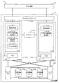
図1は実施形態の一例としてのストレージシステムの機能構成を模式的に示す図である。
Each figure is not intended to include only the components shown in the figure, and may include other functions.
[A-1] System Configuration FIG. 1 is a diagram schematically illustrating a functional configuration of a storage system as an example of an embodiment.
以下、図中において、同一の各符号は同様の部分を示しているので、その説明は省略する。
本実施形態の一例としてのストレージシステム1は、図1に示すようにRAID装置(情報処理装置)10及びホスト装置70を備える。
図1に示すように、これらのRAID装置10とホスト装置70とは、例えば、Local Area Network(LAN)で互いに通信可能に接続されている。
Hereinafter, in the drawings, the same reference numerals indicate the same parts, and the description thereof is omitted.
The
As shown in FIG. 1, the
ホスト装置70は、例えば、サーバ機能を備えたコンピュータである。図1に示す例では、1つのホスト装置70を備えているが、2つ以上のホスト装置70を備えることとしても良い。
RAID装置10は、複数(図1に示す例では2つ)のCM(制御装置)20a,20b、共有メモリ30、複数(図1に示す例では2つ)のルータ40a,40b、複数(図1に示す例では3つ)の記憶装置50a〜50c及びチャネルインタフェース60を備える。本RAID装置10は、複数の記憶装置50a〜50cを仮想的に1つの記憶装置として管理し、ホスト装置70に対して記憶領域を提供するものである。
The
The
以下、CMを示す符号としては、複数のCMのうち1つを特定する必要があるときには符号20a,20bを用いるが、任意のCMを指すときには符号20を用いる。また、以下、ルータを示す符号としては、複数のルータのうち1つを特定する必要があるときには符号40a,40bを用いるが、任意のルータを指すときには符号40を用いる。更に、以下、記憶装置を示す符号としては、複数の記憶装置のうち1つを特定する必要があるときには符号50a〜50cを用いるが、任意の記憶装置を指すときには符号50を用いる。
Hereinafter, as reference numerals indicating CMs, reference numerals 20a and 20b are used when one of a plurality of CMs needs to be specified, but reference numeral 20 is used when indicating an arbitrary CM. In the following description,
以下、CM20aをCM#0と、CM20bをCM#1という場合がある。また、以下、ルータ40aをルータ#0と、ルータ40bをルータ#1という場合がある。更に、以下、記憶装置50aを記憶装置#0と、記憶装置50bを記憶装置#1と、記憶装置50cを記憶装置#2という場合がある。
図1に示すように、CM20とチャネルインタフェース60との間、CM20と共有メモリ30との間、CM20とルータ40との間及びルータ40と記憶装置50との間は、例えば、バス線で互いに通信可能に接続されている。
Hereinafter, the CM 20a may be referred to as
As shown in FIG. 1, between the CM 20 and the
なお、図1に示す本RAID装置10が備えるCM20,ルータ40及び記憶装置50の数はこれに限定されるものではなく、例えば、CM20,ルータ40及び記憶装置50がそれぞれ図1に示す数より多くもしくはより少なく備えられても良い。
以下、CM20,ルータ40及び記憶装置50をまとめてRAID装置10の構成部品もしくは単に構成部品という場合がある。そして、本RAID装置10は、これらの構成部品における異常を検知し、異常が検知された構成部品の中から故障箇所を特定する機能を備える。
The numbers of CMs 20, routers 40, and storage devices 50 included in the
Hereinafter, the CM 20, the router 40, and the storage device 50 may be collectively referred to as a component of the
チャネルインタフェース60は、ホスト装置70と通信可能に接続するインタフェースコントローラである。チャネルインタフェース60は、ホスト装置70から送信されたデータを受信してCM20に受け渡し、又、CM20から受け取ったデータをホスト装置70に送信する。
ルータ40は、CM20と記憶装置50とを中継する既知の装置である。これらのルータ40は、互いに同様の機能構成を備える。
The
The router 40 is a known device that relays between the CM 20 and the storage device 50. These routers 40 have the same functional configuration.
記憶装置50は、データを読み書き可能に格納する既知の装置であり、例えば、Hard Disk Drive(HDD)やSolid State Drive(SSD)である。これらの記憶装置50は、互いに同様の機能構成を備える。
本実施形態の一例においては、CM#0はルータ#0又はルータ#1を介して各記憶装置50にアクセスできるように冗長化されて構成されており、CM#1もルータ#0又はルータ#1を介して各記憶装置50にアクセスできるように冗長化されて構成されている。
The storage device 50 is a known device that stores data in a readable and writable manner, and is, for example, a hard disk drive (HDD) or a solid state drive (SSD). These storage devices 50 have the same functional configuration.
In an example of the present embodiment,
図2は、実施形態の一例としてのストレージシステムにおける共有情報を例示する図である。
共有メモリ30は、CM#0及びCM#1に共有される記憶装置である。本実施形態の一例においては、共有メモリ30は、図2に示すように、RAID装置10の構成部品であるCM#0,#1、ルータ#0,#1及び記憶装置#0〜#2における異常発生回数とアクセス処理値(ともに詳細は図3を用いて後述)とを対応づけた情報を共有情報300として保持している。本RAID装置10の起動時には、各構成部品の異常発生回数及びアクセス処理値は、図2に示すように、それぞれ初期値としての0が設定されている。また、異常発生回数及びアクセス処理値の閾値についても、図3を用いて後述する。
FIG. 2 is a diagram illustrating shared information in the storage system as an example of the embodiment.
The shared
なお、図1に示す例においては、1つの共有メモリ30が各CM20の外部に備えられているが、これに限定されるものではない。例えば、各CM20が共有メモリ30をそれぞれ備え、CM20間の通信によって互いの共有メモリ30に格納されたデータを同期して一致させても良い。
CM20は、種々の制御を行なう制御装置であり、ホスト装置70からのストレージアクセス要求に従って、各種制御を行なう。
In the example shown in FIG. 1, one shared
The CM 20 is a control device that performs various controls, and performs various controls in accordance with storage access requests from the
CM#0は、Central Processing Unit(CPU;コンピュータ)21a及びメモリ22を備える。
メモリ22は、Read Only Memory(ROM)及びRandom Access Memory(RAM)を含む記憶装置である。メモリ22のROMには、Operating System(OS)、故障箇所特定の制御に係るソフトウェアプログラム(制御プログラム)やこのプログラム用のデータ類が書き込まれている。メモリ22上のソフトウェアプログラムは、CPU21aに適宜読み込まれて実行される。また、メモリ22のRAMは、一次記録メモリあるいはワーキングメモリとして利用される。
The
The
CPU21aは、種々の制御や演算を行なう処理装置であり、メモリ22に格納されたOSやプログラムを実行することにより、種々の機能を実現する。すなわち、CPU21aは、図1に示すように、異常監視部211,アクセス処理値監視部212,故障箇所特定部213及びリセット処理部214として機能する。
なお、異常監視部211,アクセス処理値監視部212,故障箇所特定部213及びリセット処理部214としての機能を実現するためのプログラム(制御プログラム)は、例えばフレキシブルディスク,CD(CD−ROM,CD−R,CD−RW等),DVD(DVD−ROM,DVD−RAM,DVD−R,DVD+R,DVD−RW,DVD+RW,HD DVD等),ブルーレイディスク,磁気ディスク,光ディスク,光磁気ディスク等の、コンピュータ読取可能な記録媒体に記録された形態で提供される。そして、コンピュータはその記録媒体から図示しない読取装置を介してプログラムを読み取って内部記録装置または外部記録装置に転送し格納して用いる。又、そのプログラムを、例えば磁気ディスク,光ディスク,光磁気ディスク等の記憶装置(記録媒体)に記録しておき、その記憶装置から通信経路を介してコンピュータに提供してもよい。
The
A program (control program) for realizing the functions as the
異常監視部211,アクセス処理値監視部212,故障箇所特定部213及びリセット処理部214としての機能を実現する際には、内部記憶装置(本実施形態ではメモリ22)に格納されたプログラムがコンピュータのマイクロプロセッサ(本実施形態ではCPU21a)によって実行される。このとき、記録媒体に記録されたプログラムをコンピュータが読み取って実行してもよい。
When realizing the functions as the
なお、本実施形態において、コンピュータとは、ハードウェアとOSとを含む概念であり、OSの制御の下で動作するハードウェアを意味している。又、OSが不要でアプリケーションプログラム単独でハードウェアを動作させるような場合には、そのハードウェア自体がコンピュータに相当する。ハードウェアは、少なくとも、CPU等のマイクロプロセッサと、記録媒体に記録されたコンピュータプログラムを読み取るための手段とをそなえており、本実施形態においては、CM20がコンピュータとしての機能を有しているのである。 In the present embodiment, the computer is a concept including hardware and an OS, and means hardware that operates under the control of the OS. Further, when the OS is unnecessary and the hardware is operated by the application program alone, the hardware itself corresponds to the computer. The hardware includes at least a microprocessor such as a CPU and means for reading a computer program recorded on a recording medium. In this embodiment, the CM 20 has a function as a computer. is there.
CM#1はCPU21b及びメモリ22を備える点でCM#0と同様であるが、CPU21bは、図1に示すように、故障箇所特定部213及びリセット処理部214として機能しない点でCPU21aとは異なる。すなわち、本実施形態の一例においては、CM#0がマスタCMとして機能し、CM#1がスレーブCMとして機能する。なお、CPU21bは、故障箇所特定部213及びリセット処理部214として機能しない点以外は、CPU21aと同様の機能構成を備えるため、その詳細な説明は省略する。
図3は、実施形態の一例としてのストレージシステムにおける異常発生回数及びアクセス処理値の計測手法を例示する図である。
異常監視部211は、各構成部品における異常を検知し、又、構成部品毎の異常発生回数を計測する。
具体的には、異常監視部211は、図1に示したRAID装置10の構成部品であるCM#0,#1、ルータ#0,#1及び記憶装置#0〜#2のいずれかで発生した異常を検知する。
FIG. 3 is a diagram illustrating a method for measuring the number of occurrences of abnormality and the access processing value in the storage system as an example of the embodiment.
The
Specifically, the
この異常監視部211による異常検知手法は、既知の種々の手法によって実現可能なため、その詳細な説明は省略する。
図3に示す例においては、CM#0,ルータ#0及び記憶装置#0で異常が発生している。このように複数の構成部品で異常が検知されるのは、例えば、CM#0がルータ#0を介して記憶装置#0に対するアクセス処理を行なっている場合である。なお、構成部品における異常の原因は、例えば、回路故障やソフトウェアエラー、記憶装置50内のチップにおける断線である。例えば、CM#0がルータ#0を介して記憶装置#0に対するアクセス処理を行なっている場合に、これらのいずれかの構成部品において回路故障等が発生すると、図3に示すようにCM#0,ルータ#0及び記憶装置#0において異常が検知される。そして、異常監視部211は、図3に示すように、これらの異常を検知する毎に対応する構成部品の異常発生回数を1ずつ加算(累計)し、共有情報300として共有メモリ30に上書きしていく。なお、異常監視部211は、後述するリセット処理部214によるリセット処理が行なわれるまで、異常発生回数の計数を継続する。
Since the abnormality detection method by the
In the example shown in FIG. 3, an abnormality has occurred in
アクセス処理値監視部212は、構成部品毎のアクセス処理値を計測する。
具体的には、アクセス処理値監視部212は、異常監視部211がいずれかの構成部品について異常発生回数の計測を開始すると、その構成部品についてのアクセス処理値の計測を開始する。
図3に示す例においては、異常監視部211がCM#0,ルータ#0及び記憶装置#0について異常発生回数の計測を開始したため、アクセス処理値監視部212は、これらCM#0,ルータ#0及び記憶装置#0についてアクセス処理値の計測を開始する。なお、アクセス処理値とは、例えば、各構成部品が処理するデータ量やコマンド(Read/Writeコマンド)発行数である。以下、特筆しない限りアクセス処理値は各構成部品が処理するデータ量であるものとする。本実施形態の一例においては、アクセス処理値として各構成部品が処理するデータ量を用いた方が高い精度での故障箇所の特定を期待できる。そして、アクセス処理値監視部212は、各構成部品が処理するデータ量が増加する毎に対応する構成部品のアクセス処理値を加算(累計)し、共有情報300として共有メモリ30に上書きしていく。なお、アクセス処理値監視部212は、異常が検知されているアクセス処理に限らず、正常なアクセス処理についても計測する。また、アクセス処理値監視部212は、後述するリセット処理部214によるリセット処理が行なわれるまで、アクセス処理値の計測を継続する。
The access processing
Specifically, when the
In the example shown in FIG. 3, since the
このアクセス処理値監視部212によるアクセス処理値の計測手法は、既知の種々の手法によって実現可能なため、その詳細な説明は省略する。
上述したように、異常監視部211及びアクセス処理値監視部212は2つのCM20がともに備える機能であるため、2つのCM20はともに上述した異常監視及びアクセス処理値監視を行ない、共有メモリ20の共有情報300を更新していく。
Since the access processing value measuring method by the access processing
As described above, since the
図1に示す例においては、CM#0はルータ#0又はルータ#1を介して3つの記憶装置50にアクセス可能であり、CM#1もルータ#0又はルータ#1を介して3つの記憶装置50にアクセス可能な冗長構成を有する。よって、CM#0の異常監視部211及びアクセス処理値監視部212は、自CM#0と2つのルータ40と3つの記憶装置50との異常監視及びアクセス処理値監視をそれぞれ行なう。一方、CM#1の異常監視部211及びアクセス処理値監視部212は、自CM#1と2つのルータ40と3つの記憶装置50との異常監視及びアクセス処理値監視をそれぞれ行なう。
In the example shown in FIG. 1,
故障箇所特定部213は、各構成部品における異常発生回数とアクセス処理値との比率に基づいて、故障箇所としての構成部品を特定する。
具体的には、故障箇所特定部213は、異常監視部211が計測するいずれかの構成部品についての異常発生回数が閾値に達すると、その構成部品における異常発生回数とアクセス処理値との比率を算出する。例えば、故障箇所特定部213は、異常発生回数をアクセス処理値で除算して比率を算出する。そして、故障箇所特定部213は、この比率が最も大きい構成部品を故障箇所として特定する。
The failure
Specifically, when the number of occurrences of abnormality for any of the component parts measured by the
図3に示す例においては、異常発生回数の閾値が10回に設定されている。つまり、異常監視部211が計測した異常発生回数が閾値である10回に同時に達した構成部品(被疑箇所)が複数ある場合には、故障箇所特定部213は、それらの被疑箇所における異常発生回数をアクセス処理値で除算した比率をそれぞれ求める。そして、故障箇所特定部213は、算出した比率が最も大きい被疑箇所(構成部品)を故障箇所として特定する。一方、異常監視部211が計測した異常発生回数が閾値である10回に達した構成部品(被疑箇所)が1つのみである場合には、故障箇所特定部213は、比率の算出をせずに、その被疑箇所(構成部品)を故障箇所として特定する。なお、故障箇所特定部213は、故障箇所を特定した際に、その故障箇所を図示しないディスプレイ等に表示させ、オペレータに提示しても良い。
In the example shown in FIG. 3, the threshold value for the number of occurrences of abnormality is set to 10. That is, when there are a plurality of component parts (suspected parts) that simultaneously have reached the threshold value of 10 times that the
例えば、CM#0,ルータ#0及び記憶装置#0における異常発生回数がそれぞれ同時に10回、10回及び10回に達し、これらの構成部品におけるアクセス処理値がそれぞれ80GB,30GB及び50Gである場合について、故障箇所の特定手法を説明する。故障箇所特定部213は、異常発生回数が図3に例示する閾値としての10回に達したCM#0,ルータ#0及び記憶装置#0を被疑箇所と判断する。また、故障箇所特定部213は、CM#0,ルータ#0及び記憶装置#0における比率をそれぞれ算出して、10/80,10/30及び10/50を得る。そして、故障箇所特定部213は、算出した比率の中で最も大きい値10/30であるルータ#0を故障箇所として特定する。
For example, the number of occurrences of abnormality in
リセット処理部214は、異常発生回数とアクセス処理値との計測をリセットさせる。
具体的には、リセット処理部214は、アクセス処理値監視部213が計測するいずれかの構成部品についてのアクセス処理値が閾値に達すると、共有情報300におけるその構成部品についての異常発生回数とアクセス処理値とをリセットする。
図3に示す例においては、アクセス処理値の閾値(単位アクセス処理値)が100GBに設定されている。つまり、アクセス処理値監視部211が計測したアクセス処理値が閾値である100GBに達した構成部品がある場合には、リセット処理部214は、共有情報300におけるその構成部品についての異常発生回数とアクセス処理値とをリセットする。なお、上述したようにアクセス処理値としてコマンド発行数を用いる場合には、アクセス処理値の閾値にはコマンド発行数が設定される。
The
Specifically, when the access processing value for any of the components measured by the access processing
In the example shown in FIG. 3, the access processing value threshold (unit access processing value) is set to 100 GB. That is, when there is a component whose access processing value measured by the access processing
すなわち、故障箇所特定部213は、アクセス処理値が単位アクセス処理値に達するまでに異常発生回数が閾値に達した構成部品を被疑箇所と判定する。言い換えれば、故障箇所特定部213は、単位アクセス処理値当たりの異常発生回数が閾値に達した構成部品を被疑箇所と判定する。
〔A−2〕動作
上述の如く構成された実施形態の一例としてのストレージシステム1における故障箇所の特定処理の一例を図4に示すフローチャート(ステップS10〜S100)に従って説明する。
That is, the failure
[A-2] Operation An example of failure point identification processing in the
故障箇所特定部213は、異常監視部211が計測するいずれかの構成部品についての異常発生回数が閾値に達したことを検知する(ステップS10)。
故障箇所特定部213は、異常監視部211が計測した異常発生回数が閾値に達した構成部品(被疑箇所)が1箇所のみであるかを判定する(ステップS20)。
被疑箇所が1箇所のみである場合には(ステップS20のYESルート参照)、故障箇所特定部213は、閾値に達した構成部品を故障箇所として特定する(ステップS30)。
The failure
The failure
If there is only one suspicious location (see YES route in step S20), the failure
被疑箇所が1箇所のみでない場合には(ステップS20のNOルート参照)、故障箇所特定部213は、それらの被疑箇所における異常発生回数をアクセス処理値で除算した比率をそれぞれ求める。
以下のステップS40〜S100においては、被疑箇所がCM#0,ルータ#0及び記憶装置#0である場合について説明する。
When the suspected place is not only one place (refer to the NO route in step S20), the failure
In the following steps S40 to S100, the case where the suspected places are
故障箇所特定部213は、被疑箇所のうちCM#0の比率が最大であるかを判定する(ステップS40)。
被疑箇所のうちCM#0の比率が最大である場合には(ステップS40のYESルート参照)、故障箇所特定部213は、CM#0を故障箇所として特定する(ステップS50)。例えば、正常なCM#1と異常なCM#0とが正常な1つの記憶装置#0に対してアクセスした場合には、このステップS50に到達する。
The failure
When the ratio of
被疑箇所のうちCM#0の比率が最大でない場合には(ステップS40のNOルート参照)、故障箇所特定部213は、被疑箇所のうちルータ#0の比率が最大であるかを判定する(ステップS60)。
被疑箇所のうちルータ#0の比率が最大である場合には(ステップS60のYESルート参照)、故障箇所特定部213は、ルータ#0を故障箇所として特定する(ステップS70)。
When the ratio of
When the ratio of the
被疑箇所のうちルータ#0の比率が最大でない場合には(ステップS60のNOルート参照)、故障箇所特定部213は、被疑箇所のうち記憶装置#0の比率が最大であるかを判定する(ステップS80)。
被疑箇所のうち記憶装置#0の比率が最大である場合には(ステップS80のYESルート参照)、故障箇所特定部213は、記憶装置#0を故障箇所として特定する(ステップS90)。例えば、正常な1つのCM#0が正常な複数の記憶装置#1,#2と異常な1つの記憶装置#0とに対してアクセスした場合には、このステップS90に到達する。
When the ratio of the
When the ratio of the
被疑箇所のうち記憶装置#0の比率が最大でない場合、つまり、2以上の被疑箇所における比率が同値の場合には(ステップS80のNOルート参照)、故障箇所特定部213は、故障箇所は不定であると判断する(ステップS100)。例えば、1つのCM#0が1つの記憶装置#0に対してのみアクセスした場合には、このステップS100に到達する。CM#0から他の記憶装置#1,#2へのアクセスや他のCM#1から記憶装置#0へのアクセスが一切ないため、統計的に故障箇所を特定することは困難である。ただし、大規模なRAID装置においては、複数の記憶装置を使用したRAID構成で運用するのが通常であり、1つの記憶装置のみにアクセスが集中するのはRAID0(1つの記憶装置)のみでの運用ということとなり、通常はありえないケースとなる。
When the ratio of the
以上のステップS30,S50,S70,S90又はS100に到達すると、本故障箇所の特定処理の一例は終了する。
なお、故障箇所特定部213による比率が最大であるかについての判定(ステップS40,S60,S80)の回数は被疑箇所の数によって決まるため、図4に示した例に限定されるものではない。また、障箇所特定部213による比率が最大であるかについての判定(ステップS40,S60,S80)の順序も図4に示した例に限定されるものではなく、故障箇所特定部213は、例えば、ステップS80,S60,S40の順に判定しても良い。更に、故障箇所特定部213は、故障箇所を特定した際には(ステップS30,S50,S70,S90)、その故障箇所を図示しないディスプレイ等に表示させ、オペレータに提示しても良い。一方、故障箇所特定部213は、故障箇所は不定であると判断した際には(ステップS100)、故障箇所が不定であるというメッセージを図示しないディスプレイ等に表示させ、オペレータに提示しても良い。
When the above steps S30, S50, S70, S90, or S100 are reached, an example of the processing for identifying the fault location ends.
Note that the number of determinations (steps S40, S60, and S80) regarding whether or not the ratio by the failure
次に、上述の如く構成された実施形態の一例としてのストレージシステム1における異常発生回数及びアクセス処理値のリセット処理の一例を図5に示すフローチャート(ステップS110〜S180)に従って説明する。図5に示す例においては、図1に示したようにRAID装置10が構成部品として2つのCM20,2つのルータ40及び3つの記憶装置50を備える例について説明する。
Next, an example of the reset processing of the number of occurrences of abnormality and the access processing value in the
リセット処理部214は、アクセス処理値監視部212が計測するいずれかの構成部品についてのアクセス処理値が閾値に達したことを検知する(ステップS110)。
リセット処理部214は、アクセス処理値監視部212が計測したCM#0におけるアクセス処理値が閾値に達したかを判定する(ステップS120)。
アクセス処理値監視部212が計測したCM#0におけるアクセス処理値が閾値に達した場合には(ステップS120のYESルート参照)、リセット処理部214は、CM#0における異常発生回数及びアクセス処理値の計測をリセットさせ(ステップS130)、ステップS140に移行する。
The
The
When the access processing value in
アクセス処理値監視部212が計測したCM#0におけるアクセス処理値が閾値に達していない場合には(ステップS120のNOルート参照)、直接ステップS140に移行する。
リセット処理部214は、アクセス処理値監視部212が計測したCM#1におけるアクセス処理値が閾値に達したかを判定する(ステップS140)。
When the access processing value in
The
アクセス処理値監視部212が計測したCM#1におけるアクセス処理値が閾値に達した場合には(ステップS140のYESルート参照)、リセット処理部214は、CM#1における異常発生回数及びアクセス処理値の計測をリセットさせ(ステップS150)、次の処理に移行する。
アクセス処理値監視部212が計測したCM#1におけるアクセス処理値が閾値に達していない場合には(ステップS140のNOルート参照)、次の構成部品についての判定処理に移行する。
When the access processing value in
When the access processing value in
そして、リセット処理部214は、同様にルータ#0及び記憶装置#0,#1についての判定処理及びリセット処理を行なう。
更に、リセット処理部214は、アクセス処理値監視部212が計測した記憶装置#2におけるアクセス処理値が閾値に達したかを判定する(ステップS160)。
アクセス処理値監視部212が計測した記憶装置#2におけるアクセス処理値が閾値に達した場合には(ステップS160のYESルート参照)、リセット処理部214は、記憶装置#2における異常発生回数及びアクセス処理値の計測をリセットさせ(ステップS170)、ステップS180に移行する。
Similarly, the
Furthermore, the
When the access processing value in the
アクセス処理値監視部212が計測した記憶装置#2におけるアクセス処理値が閾値に達していない場合には(ステップS160のNOルート参照)、直接ステップS180に移行する。
以上で、リセットが完了し(ステップS180)、本リセット処理の一例が終了する。
なお、リセット処理部214によるアクセス処理値が閾値に達したかの判定(ステップS120,S140,…,S160)の順序は図5に示した例に限定されるものではない。リセット処理部214は、例えば、ステップS160,…,S140,S120の順に判定しても良い。
If the access processing value in the
Thus, the reset is completed (step S180), and the example of the reset process is completed.
Note that the order of determining whether the access processing value by the
〔A−3〕効果
このように、実施形態の一例としてのストレージシステム1によれば、以下のような効果を奏することができる。
すなわち、1つの構成部品の故障により複数の構成部品において異常が検知された場合でも、故障箇所を特定することができる。
[A-3] Effects As described above, according to the
That is, even when an abnormality is detected in a plurality of component parts due to a failure of one component part, the failure location can be specified.
例えば、正常なCM#1と異常なCM#0とが正常な1つの記憶装置#0に対してアクセスした場合には、故障したCM#0が正常な記憶装置#0へアクセスすることになる。そのため、CM#0と記憶装置#0との異常発生回数は互いに同値となり、単に異常発生が検知された構成部品の異常発生回数を計数し、この異常発生回数が多い構成部品を故障箇所とする手法では故障箇所が特定できない。本ストレージシステム1によれば、アクセス処理値監視部212が正常なCM#1から正常な記憶装置#0に対するアクセス処理値の計測をする。そして、記憶装置#0におけるアクセス処理値が増加し、記憶装置#0における比率が減少する。従って、故障箇所特定部213は、故障したCM#0の比率が正常な記憶装置#0の比率よりも大きいと判定することができ、故障箇所を特定することができる。このため、故障箇所の特定における信頼性を向上させることができる。
For example, when a
また、例えば、正常な1つのCM#0が正常な複数の記憶装置#1,#2と異常な1つの記憶装置#0とに対してアクセスした場合には、正常なCM#0が故障した記憶装置#0へアクセスすることになる。このために、単に異常発生が検知された構成部品の異常発生回数を計数するだけでは、CM#0と記憶装置#0との異常発生回数は互いに同値となり、故障箇所が特定できない。本ストレージシステム1によれば、アクセス処理値監視部212が正常なCM#0から正常な記憶装置#1,#2に対するアクセス処理値の計測をする。そして、CM#0におけるアクセス処理値が増加し、CM#0における比率が減少する。従って、故障箇所特定部213は、故障した記憶装置#0の比率が正常なCM#0の比率よりも大きいと判定することができ、故障箇所を特定することができる。このため、故障箇所の特定における信頼性を向上させることができる。なお、一般的なRAID装置においては、複数の記憶装置を使用したRAID構成での運用を行なうため、1つのCMが複数の記憶装置へ同時にアクセスするケースが多い。よって、正常な1つのCM#0が正常な複数の記憶装置#1,#2と異常な1つの記憶装置#0とに対してアクセスする場合において、故障箇所の特定ができるという効果は特に有効である。
Also, for example, when one
更に、故障した1つのCM20が正常な1つの記憶装置50に集中的にアクセスした場合でも、他の正常なCM20からその記憶装置50へアクセスが行なわれれば、正常な記憶装置50における比率が低下する。そして、故障箇所特定部213は、記憶装置アクセスエラーの発生原因(故障箇所)を特定することができる。このため、故障箇所の特定における信頼性を向上させることができる。
Further, even when one failed CM 20 accesses the one normal storage device 50 in a concentrated manner, if the other normal CM 20 accesses the storage device 50, the ratio in the normal storage device 50 decreases. To do. The failure
また、正常な1つのCM20から故障した1つの記憶装置50にアクセスを行なった場合でも、正常なCM20から他の正常な記憶装置50へのアクセスが行なわれていれば、正常なCM20における比率が低下する。そして、故障箇所特定部213は、記憶装置アクセスエラーの発生原因(故障箇所)を特定することができる。このため、故障箇所の特定における信頼性を向上させることができる。
Further, even when one defective storage device 50 is accessed from one normal CM 20, if the normal CM 20 is accessed from another normal storage device 50, the ratio in the normal CM 20 is increased. descend. The failure
所定のエラー監視期間が経過したことにより異常発生回数及びアクセス処理値をリセットすると、アクセス頻度が少ない被疑箇所(構成部品)を故障箇所として特定することは困難である。本ストレージシステム1によれば、リセット処理部214がアクセス処理値が閾値に達した被疑箇所(構成部品)についての異常発生回数及びアクセス処理値をリセットさせることにより、アクセス頻度が少ない被疑箇所(構成部品)についても故障箇所として特定することができる。このため、故障箇所の特定における信頼性を向上させることができる。
If the number of occurrences of an abnormality and the access processing value are reset after a predetermined error monitoring period has elapsed, it is difficult to specify a suspected part (component) having a low access frequency as a faulty part. According to the
〔B〕その他
開示の技術は上述した実施形態に限定されるものではなく、本実施形態の趣旨を逸脱しない範囲で種々変形して実施することができる。本実施形態の各構成及び各処理は、必要に応じて取捨選択することができ、あるいは適宜組み合わせてもよい。
上述した実施形態の一例においては、CM#1がCPU21bを備えることとしたが、これに限定されるものではなく、例えば、CM#1がCM#0と同様のCPU21aを備えることとしても良い。これにより、例えば、CM#0が故障した際にも、CM#1によって故障箇所の特定を行なうことができる。
[B] Others The disclosed technology is not limited to the above-described embodiment, and various modifications can be made without departing from the spirit of the present embodiment. Each structure and each process of this embodiment can be selected as needed, or may be combined suitably.
In the example of the embodiment described above, the
また、上述した実施形態の一例においては、故障箇所特定部213が被疑箇所における異常発生回数をアクセス処理値で除算した比率を求めることとしたが、これに限定されるものではない。例えば、故障箇所特定部213が被疑箇所におけるアクセス処理値を異常発生回数で除算した比率を求めることとしても良い。この場合には、故障箇所特定部213は、求めた比率が最も小さい被疑箇所を故障箇所として特定する。
In the example of the embodiment described above, the failure
更に、上述した実施形態の一例においては、RAID装置について説明したが、これに限定されるものではない。上述した実施形態の一例は、例えば、ネットワーク等の通信回線を介して接続された種々の電子機器を構成部品としたシステムに適用することができる。
〔C〕付記
(付記1)
複数の構成部品を備える情報処理装置であって、
前記構成部品における異常を検知すると、前記構成部品毎の異常発生回数を計測する異常監視部と、
前記構成部品毎のアクセス処理値を計測するアクセス処理値監視部と、
前記構成部品における前記異常発生回数と前記アクセス処理値との比率に基づいて、故障箇所としての構成部品を特定する故障箇所特定部と、
を備えることを特徴とする情報処理装置。
Furthermore, in the example of the embodiment described above, the RAID device has been described, but the present invention is not limited to this. An example of the above-described embodiment can be applied to a system including various electronic devices connected via a communication line such as a network, for example.
[C] Appendix (Appendix 1)
An information processing apparatus comprising a plurality of components,
When detecting an abnormality in the component, an abnormality monitoring unit that measures the number of occurrences of abnormality for each component,
An access processing value monitoring unit for measuring an access processing value for each component;
Based on the ratio between the number of occurrences of abnormality in the component and the access processing value, a failure location identifying unit that identifies a component as a failure location,
An information processing apparatus comprising:
(付記2)
前記アクセス処理値監視部は、
前記異常監視部がいずれかの構成部品について前記異常発生回数の計測を開始すると、当該構成部品についての前記アクセス処理値の計測を開始することを特徴とする付記1記載の情報処理装置。
(Appendix 2)
The access processing value monitoring unit
The information processing apparatus according to
(付記3)
前記故障箇所特定部は、
前記異常監視部が計測するいずれかの構成部品についての前記異常発生回数が閾値に達すると、当該構成部品における前記比率を算出することを特徴とする付記1又は2に記載の情報処理装置。
(Appendix 3)
The failure location identifying unit is
The information processing apparatus according to
(付記4)
前記故障箇所特定部は、
前記複数の構成部品のうち、前記異常発生回数を前記アクセス処理値で除算して求める前記比率が最も大きい構成部品を前記故障箇所として特定することを特徴とする付記1〜3のいずれか1項に記載の情報処理装置。
(Appendix 4)
The failure location identifying unit is
Any one of
(付記5)
前記アクセス処理値監視部が計測するいずれかの構成部品についての前記アクセス処理値が閾値に達すると、当該構成部品についての前記異常発生回数と前記アクセス処理値との計測をリセットさせるリセット処理部
を備えることを特徴とする付記1〜4のいずれか1項に記載の情報処理装置。
(Appendix 5)
A reset processing unit that resets the measurement of the number of occurrences of the abnormality and the access processing value for the component when the access processing value for any component measured by the access processing value monitoring unit reaches a threshold; The information processing apparatus according to any one of
(付記6)
前記アクセス処理値は、前記複数の構成部品が処理するデータ量であることを特徴とする付記1〜5のいずれか1項に記載の情報処理装置。
(付記7)
前記アクセス処理値は、前記複数の構成部品が処理するコマンド数であることを特徴とする付記1〜5のいずれか1項に記載の情報処理装置。
(Appendix 6)
The information processing apparatus according to any one of
(Appendix 7)
The information processing apparatus according to any one of
(付記8)
複数の構成部品を備える情報処理装置に備えられ、
前記構成部品における異常を検知すると、前記構成部品毎の異常発生回数を計測する異常監視部と、
前記構成部品毎のアクセス処理値を計測するアクセス処理値監視部と、
前記構成部品における前記異常発生回数と前記アクセス処理値との比率に基づいて、故障箇所としての構成部品を特定する故障箇所特定部と、
を備えることを特徴とする制御装置。
(Appendix 8)
Provided in an information processing apparatus including a plurality of components;
When detecting an abnormality in the component, an abnormality monitoring unit that measures the number of occurrences of abnormality for each component,
An access processing value monitoring unit for measuring an access processing value for each component;
Based on the ratio between the number of occurrences of abnormality in the component and the access processing value, a failure location identifying unit that identifies a component as a failure location,
A control device comprising:
(付記9)
前記アクセス処理値監視部は、
前記異常監視部がいずれかの構成部品について前記異常発生回数の計測を開始すると、当該構成部品についての前記アクセス処理値の計測を開始することを特徴とする付記8記載の制御装置。
(Appendix 9)
The access processing value monitoring unit
9. The control device according to appendix 8, wherein when the abnormality monitoring unit starts measuring the number of occurrences of abnormality for any one of the component parts, measurement of the access processing value for the component part is started.
(付記10)
前記故障箇所特定部は、
前記異常監視部が計測するいずれかの構成部品についての前記異常発生回数が閾値に達すると、当該構成部品における前記比率を算出することを特徴とする付記8又は9に記載の制御装置。
(Appendix 10)
The failure location identifying unit is
The control device according to appendix 8 or 9, wherein when the number of occurrences of abnormality for any of the component parts measured by the abnormality monitoring unit reaches a threshold value, the ratio of the component parts is calculated.
(付記11)
前記故障箇所特定部は、
前記複数の構成部品のうち、前記異常発生回数を前記アクセス処理値で除算して求める前記比率が最も大きい構成部品を前記故障箇所として特定することを特徴とする付記8〜10のいずれか1項に記載の制御装置。
(Appendix 11)
The failure location identifying unit is
Any one of appendixes 8 to 10, wherein the component having the largest ratio obtained by dividing the number of occurrences of the abnormality by the access processing value among the plurality of components is specified as the failure location. The control device described in 1.
(付記12)
前記アクセス処理値監視部が計測するいずれかの構成部品についての前記アクセス処理値が閾値に達すると、当該構成部品についての前記異常発生回数と前記アクセス処理値との計測をリセットさせるリセット処理部
を備えることを特徴とする付記8〜11のいずれか1項に記載の制御装置。
(Appendix 12)
A reset processing unit that resets the measurement of the number of occurrences of the abnormality and the access processing value for the component when the access processing value for any component measured by the access processing value monitoring unit reaches a threshold; The control device according to any one of appendices 8 to 11, wherein the control device is provided.
(付記13)
前記アクセス処理値は、前記複数の構成部品が処理するデータ量であることを特徴とする付記8〜12のいずれか1項に記載の制御装置。
(付記14)
前記アクセス処理値は、前記複数の構成部品が処理するコマンド数であることを特徴とする付記8〜12のいずれか1項に記載の制御装置。
(Appendix 13)
The control device according to any one of appendices 8 to 12, wherein the access processing value is a data amount processed by the plurality of component parts.
(Appendix 14)
The control device according to any one of appendices 8 to 12, wherein the access processing value is the number of commands processed by the plurality of component parts.
(付記15)
複数の構成部品を備える情報処理装置に備えられるコンピュータに、
前記構成部品における異常を検知すると、前記構成部品毎の異常発生回数を計測し、
前記構成部品毎のアクセス処理値を計測し、
前記構成部品における前記異常発生回数と前記アクセス処理値との比率に基づいて、故障箇所としての構成部品を特定する
処理を実行させることを特徴とする制御プログラム。
(Appendix 15)
In a computer included in an information processing apparatus including a plurality of components,
When detecting an abnormality in the component, measure the number of occurrences of abnormality for each component,
Measure the access processing value for each component,
A control program for executing a process of specifying a component as a failure location based on a ratio between the number of occurrences of abnormality in the component and the access processing value.
(付記16)
いずれかの構成部品について前記異常発生回数の計測を開始すると、当該構成部品についての前記アクセス処理値の計測を開始する処理を前記コンピュータに実行させることを特徴とする付記15記載の制御プログラム。
(付記17)
いずれかの構成部品についての前記異常発生回数が閾値に達すると、当該構成部品における前記比率を算出する処理を前記コンピュータに実行させることを特徴とする付記15又は16に記載の制御プログラム。
(Appendix 16)
The control program according to supplementary note 15, wherein when the measurement of the number of occurrences of abnormality is started for any one of the component parts, the computer is caused to execute a process for starting the measurement of the access processing value for the component part.
(Appendix 17)
The control program according to appendix 15 or 16, wherein when the number of occurrences of abnormality for any one of the component parts reaches a threshold value, the computer executes the process of calculating the ratio of the component part.
(付記18)
前記複数の構成部品のうち、前記異常発生回数を前記アクセス処理値で除算して求める前記比率が最も大きい構成部品を前記故障箇所として特定する処理を前記コンピュータに実行させることを特徴とする付記15〜17のいずれか1項に記載の制御プログラム。
(付記19)
いずれかの構成部品についての前記アクセス処理値が閾値に達すると、当該構成部品についての前記異常発生回数と前記アクセス処理値との計測をリセットさせる
処理を前記コンピュータに実行させることを特徴とする付記15〜18のいずれか1項に記載の制御プログラム。
(Appendix 18)
Appendix 15: causing the computer to execute a process of identifying a component having the largest ratio obtained by dividing the number of occurrences of abnormality by the access processing value among the plurality of components as the failure location. The control program according to any one of -17.
(Appendix 19)
When the access processing value for any component reaches a threshold, the computer is caused to execute a process for resetting the measurement of the number of occurrences of the abnormality and the access processing value for the component. The control program according to any one of 15 to 18.
(付記20)
前記アクセス処理値は、前記複数の構成部品が処理するデータ量であることを特徴とする付記15〜19のいずれか1項に記載の制御プログラム。
(付記21)
前記アクセス処理値は、前記複数の構成部品が処理するコマンド数であることを特徴とする付記15〜19のいずれか1項に記載の制御プログラム。
(Appendix 20)
The control program according to any one of appendices 15 to 19, wherein the access processing value is a data amount processed by the plurality of component parts.
(Appendix 21)
The control program according to any one of appendices 15 to 19, wherein the access processing value is the number of commands processed by the plurality of component parts.
1 ストレージシステム
10 RAID装置(情報処理装置)
20 CM(制御装置,構成部品)
21 CPU(コンピュータ)
211 異常監視部
212 アクセス処理値監視部
213 故障箇所特定部
214 リセット処理部
22 メモリ
30 共有メモリ
300 共有情報
40 ルータ(構成部品)
50 記憶装置(構成部品)
60 チャネルインタフェース
70 ホスト装置
1
20 CM (control device, component)
21 CPU (computer)
211
50 Storage device (component)
60
Claims (9)
前記複数の構成部品のうちのいずれかの構成部品における異常を検知すると、前記構成部品毎の異常発生回数を計測する異常監視部と、
前記異常監視部が前記いずれかの構成部品について前記異常発生回数の計測を開始すると、当該構成部品についてのアクセス処理値の計測を開始するアクセス処理値監視部と、
前記構成部品における前記異常発生回数と前記アクセス処理値との比率に基づいて、故障箇所としての構成部品を特定する故障箇所特定部と、
を備えることを特徴とする情報処理装置。 An information processing apparatus comprising a plurality of components,
When detecting an abnormality in any one of the plurality of component parts, an abnormality monitoring unit that measures the number of occurrences of abnormality for each of the component parts;
When the abnormality monitoring unit starts measuring of the abnormality occurrence count for said one of the components, the access processing value monitoring unit starts measuring the access process values for the components,
Based on the ratio between the number of occurrences of abnormality in the component and the access processing value, a failure location identifying unit that identifies a component as a failure location,
The information processing apparatus comprising: a.
前記アクセス処理値監視部が前記アクセス処理値を計測する前記いずれかの構成部品について、前記異常監視部によって計測された前記異常発生回数が閾値に達すると、当該構成部品における前記比率を算出することを特徴とする請求項1に記載の情報処理装置。 The failure location identifying unit is
For said one of the components said access processing value monitoring unit measures the access process value, when the abnormality occurrence count measured by the abnormality monitoring unit reaches a threshold, it calculates the ratio in the component The information processing apparatus according to claim 1 .
前記複数の構成部品のうち、前記異常発生回数を前記アクセス処理値で除算して求める前記比率が最も大きい構成部品を前記故障箇所として特定することを特徴とする請求項1又は2に記載の情報処理装置。 The failure location identifying unit is
3. The information according to claim 1, wherein among the plurality of component parts, the component part having the largest ratio obtained by dividing the number of occurrences of the abnormality by the access processing value is specified as the failure location. processing equipment.
を備えることを特徴とする請求項1〜3のいずれか1項に記載の情報処理装置。 Wherein the access processing value monitoring unit reaches the access processing value threshold for said one of the components to be measured, the reset unit for resetting the measurement of the access processing value and the abnormality occurrence count for that component the information processing apparatus according to any one of claims 1 to 3, characterized in that it comprises.
第1の制御装置に備えられ、前記複数の構成部品のうち前記第1の制御装置に接続された構成部品における異常を検知すると、当該構成部品毎の異常発生回数を計測するとともに、当該構成部品毎のアクセス処理値を計測する第1の監視部と、 When an abnormality is detected in a component connected to the first controller among the plurality of components provided in the first controller, the number of occurrences of the abnormality for each component is measured, and the component A first monitoring unit that measures an access processing value for each;
第2の制御装置に備えられ、前記複数の構成部品のうち前記第2の制御装置に接続された構成部品における異常を検知すると、当該構成部品毎の異常発生回数を計測するとともに、当該構成部品毎のアクセス処理値を計測する第2の監視部と、 When an abnormality is detected in a component connected to the second controller among the plurality of components provided in the second controller, the number of occurrences of the abnormality for each component is measured, and the component A second monitoring unit that measures an access processing value for each;
前記第1の監視部によって計測された異常発生回数及びアクセス処理値と、前記第2の監視部によって計測された異常発生回数及びアクセス処理値と、を記憶する記憶部と、 A storage unit for storing the number of occurrences of abnormality and the access processing value measured by the first monitoring unit, and the number of occurrences of abnormality and the access processing value measured by the second monitoring unit;
前記記憶部に記憶された前記異常発生回数と前記アクセス処理値との比率に基づいて、故障箇所としての構成部品を特定する故障箇所特定部と、 Based on the ratio between the number of occurrences of abnormality and the access processing value stored in the storage unit, a failure location identifying unit that identifies a component as a failure location,
を備えることを特徴とする情報処理装置。An information processing apparatus comprising:
前記複数の構成部品のうちのいずれかの構成部品における異常を検知すると、前記構成部品毎の異常発生回数を計測する異常監視部と、
前記異常監視部が前記いずれかの構成部品について前記異常発生回数の計測を開始すると、当該構成部品についてのアクセス処理値の計測を開始するアクセス処理値監視部と、
前記構成部品における前記異常発生回数と前記アクセス処理値との比率に基づいて、故障箇所としての構成部品を特定する故障箇所特定部と、
を備えることを特徴とする制御装置。 Provided in an information processing apparatus including a plurality of components;
When detecting an abnormality in any one of the plurality of component parts, an abnormality monitoring unit that measures the number of occurrences of abnormality for each of the component parts;
When the abnormality monitoring unit starts measuring of the abnormality occurrence count for said one of the components, the access processing value monitoring unit starts measuring the access process values for the components,
Based on the ratio between the number of occurrences of abnormality in the component and the access processing value, a failure location identifying unit that identifies a component as a failure location,
A control device comprising:
前記複数の構成部品のうちのいずれかの構成部品における異常を検知すると、前記構成部品毎の異常発生回数を計測し、
前記いずれかの構成部品について前記異常発生回数の計測を開始すると、当該構成部品についてのアクセス処理値の計測を開始し、
前記構成部品における前記異常発生回数と前記アクセス処理値との比率に基づいて、故障箇所としての構成部品を特定する
処理を実行させることを特徴とする制御プログラム。 In a computer included in an information processing apparatus including a plurality of components,
Upon detecting an abnormality in any one of the plurality of component parts, the number of occurrences of the abnormality for each component part is measured,
When the measurement of the number of occurrences of the abnormality is started for any of the component parts , the measurement of the access processing value for the component part is started ,
A control program for executing a process of specifying a component as a failure location based on a ratio between the number of occurrences of abnormality in the component and the access processing value.
Priority Applications (2)
| Application Number | Priority Date | Filing Date | Title |
|---|---|---|---|
| JP2013104098A JP6212947B2 (en) | 2013-05-16 | 2013-05-16 | Information processing apparatus, control apparatus, and control program |
| US14/256,077 US9459943B2 (en) | 2013-05-16 | 2014-04-18 | Fault isolation by counting abnormalities |
Applications Claiming Priority (1)
| Application Number | Priority Date | Filing Date | Title |
|---|---|---|---|
| JP2013104098A JP6212947B2 (en) | 2013-05-16 | 2013-05-16 | Information processing apparatus, control apparatus, and control program |
Publications (2)
| Publication Number | Publication Date |
|---|---|
| JP2014225133A JP2014225133A (en) | 2014-12-04 |
| JP6212947B2 true JP6212947B2 (en) | 2017-10-18 |
Family
ID=51896806
Family Applications (1)
| Application Number | Title | Priority Date | Filing Date |
|---|---|---|---|
| JP2013104098A Active JP6212947B2 (en) | 2013-05-16 | 2013-05-16 | Information processing apparatus, control apparatus, and control program |
Country Status (2)
| Country | Link |
|---|---|
| US (1) | US9459943B2 (en) |
| JP (1) | JP6212947B2 (en) |
Families Citing this family (3)
| Publication number | Priority date | Publication date | Assignee | Title |
|---|---|---|---|---|
| US9495235B2 (en) * | 2013-11-18 | 2016-11-15 | Hitachi, Ltd. | Identifying a physical device in which a fault has occurred in a storage system |
| CN107992415B (en) * | 2017-11-28 | 2021-04-16 | 中国银联股份有限公司 | Fault positioning and analyzing method of transaction system and related server |
| JP2020086538A (en) * | 2018-11-15 | 2020-06-04 | 株式会社日立製作所 | Computer system, and device management method |
Family Cites Families (23)
| Publication number | Priority date | Publication date | Assignee | Title |
|---|---|---|---|---|
| US4380067A (en) * | 1981-04-15 | 1983-04-12 | International Business Machines Corporation | Error control in a hierarchical system |
| JPS62198944A (en) * | 1986-02-27 | 1987-09-02 | Toshiba Corp | Detecting system for device abnormality |
| JPH01271828A (en) | 1988-04-22 | 1989-10-30 | Nec Corp | Preventive maintenance system for magnetic disk device |
| JPH04219676A (en) * | 1990-12-19 | 1992-08-10 | Nec Corp | Quality control system for memory medium |
| JPH04321140A (en) * | 1991-04-22 | 1992-11-11 | Fujitsu Ltd | Method and device for pointing error occurring part |
| JPH05274629A (en) * | 1992-03-27 | 1993-10-22 | Nec Corp | Information processor |
| JP3212677B2 (en) * | 1992-04-07 | 2001-09-25 | 日本電気株式会社 | Peripheral control device |
| WO1996020549A1 (en) * | 1994-12-23 | 1996-07-04 | British Telecommunications Public Limited Company | Fault monitoring |
| JPH11296311A (en) * | 1998-04-08 | 1999-10-29 | Hitachi Ltd | System for controlling fault resistance in storage device |
| JPH11353819A (en) | 1998-06-08 | 1999-12-24 | Nec Software Hokkaido Ltd | Disk device and its prevention maintenance method |
| US6816461B1 (en) * | 2000-06-16 | 2004-11-09 | Ciena Corporation | Method of controlling a network element to aggregate alarms and faults of a communications network |
| US7058844B2 (en) * | 2001-06-15 | 2006-06-06 | Sun Microsystems, Inc. | System and method for rapid fault isolation in a storage area network |
| GB2376612B (en) * | 2001-06-15 | 2004-06-09 | Ibm | Method and apparatus for fault location in a loop network |
| JP2003114811A (en) * | 2001-10-05 | 2003-04-18 | Nec Corp | Method and system for automatic failure recovery and apparatus and program therefor |
| US7437611B2 (en) * | 2004-10-21 | 2008-10-14 | International Business Machines Corporation | System and method for problem determination using dependency graphs and run-time behavior models |
| JP2007299213A (en) * | 2006-04-28 | 2007-11-15 | Fujitsu Ltd | Raid controller and fault monitoring method |
| US7779306B1 (en) * | 2007-03-23 | 2010-08-17 | Emc Corporation | Method for automatically diagnosing hardware faults in a data storage system |
| JP4968078B2 (en) | 2008-01-16 | 2012-07-04 | ソニー株式会社 | Failure diagnosis apparatus and failure diagnosis method |
| JP5186982B2 (en) * | 2008-04-02 | 2013-04-24 | 富士通株式会社 | Data management method and switch device |
| JP4627327B2 (en) | 2008-05-23 | 2011-02-09 | 富士通株式会社 | Abnormality judgment device |
| US8069370B1 (en) * | 2010-07-02 | 2011-11-29 | Oracle International Corporation | Fault identification of multi-host complex systems with timesliding window analysis in a time series |
| US8230262B2 (en) * | 2010-07-02 | 2012-07-24 | Oracle International Corporation | Method and apparatus for dealing with accumulative behavior of some system observations in a time series for Bayesian inference with a static Bayesian network model |
| JP5618204B2 (en) * | 2010-11-17 | 2014-11-05 | Necプラットフォームズ株式会社 | Fault processing apparatus, information processing apparatus using the same, and fault processing method for information processing apparatus |
-
2013
- 2013-05-16 JP JP2013104098A patent/JP6212947B2/en active Active
-
2014
- 2014-04-18 US US14/256,077 patent/US9459943B2/en active Active
Also Published As
| Publication number | Publication date |
|---|---|
| JP2014225133A (en) | 2014-12-04 |
| US9459943B2 (en) | 2016-10-04 |
| US20140344630A1 (en) | 2014-11-20 |
Similar Documents
| Publication | Publication Date | Title |
|---|---|---|
| US20200159635A1 (en) | Memory Fault Detection | |
| CN105468484B (en) | Method and apparatus for locating a fault in a storage system | |
| US8443237B2 (en) | Storage apparatus and method for controlling the same using loopback diagnosis to detect failure | |
| US7412631B2 (en) | Methods and structure for verifying domain functionality | |
| US8832501B2 (en) | System and method of processing failure | |
| TWI632462B (en) | Switching device and method for detecting i2c bus | |
| US11176020B2 (en) | Server status monitoring system and method using baseboard management controller | |
| TW201414257A (en) | System and method for monitoring storage devices | |
| JP6212947B2 (en) | Information processing apparatus, control apparatus, and control program | |
| US10606490B2 (en) | Storage control device and storage control method for detecting storage device in potential fault state | |
| JP5488709B2 (en) | Reference time setting method in storage control device | |
| JP5419819B2 (en) | Computer system management method and management system | |
| JP2011086244A (en) | Storage system, control device, and diagnostic method | |
| JP2007299213A (en) | Raid controller and fault monitoring method | |
| JP5440073B2 (en) | Information processing apparatus, information processing apparatus control method, and control program | |
| JP2006092070A (en) | Disk array device, its control method and control program | |
| JP5689783B2 (en) | Computer, computer system, and failure information management method | |
| JP5273185B2 (en) | Recording medium control system, recording medium control method, and recording medium control program | |
| CN111190781A (en) | Test self-check method of server system | |
| JP2013196410A (en) | Server device and failure management method and failure management program | |
| JP2001014113A (en) | Disk device fault detection system | |
| JP2017090959A (en) | Storage device, performance estimation program, and performance estimation method | |
| JP2009282848A (en) | Abnormality determining apparatus | |
| JP5729238B2 (en) | Management server, abnormality prediction system, abnormality prediction method, and abnormality prediction program | |
| TWI607455B (en) | Method for memory data detection |
Legal Events
| Date | Code | Title | Description |
|---|---|---|---|
| A621 | Written request for application examination |
Free format text: JAPANESE INTERMEDIATE CODE: A621 Effective date: 20160226 |
|
| A977 | Report on retrieval |
Free format text: JAPANESE INTERMEDIATE CODE: A971007 Effective date: 20161227 |
|
| A131 | Notification of reasons for refusal |
Free format text: JAPANESE INTERMEDIATE CODE: A131 Effective date: 20170117 |
|
| A521 | Written amendment |
Free format text: JAPANESE INTERMEDIATE CODE: A523 Effective date: 20170321 |
|
| TRDD | Decision of grant or rejection written | ||
| A01 | Written decision to grant a patent or to grant a registration (utility model) |
Free format text: JAPANESE INTERMEDIATE CODE: A01 Effective date: 20170822 |
|
| A61 | First payment of annual fees (during grant procedure) |
Free format text: JAPANESE INTERMEDIATE CODE: A61 Effective date: 20170904 |
|
| R150 | Certificate of patent or registration of utility model |
Ref document number: 6212947 Country of ref document: JP Free format text: JAPANESE INTERMEDIATE CODE: R150 |