JP6212415B2 - Magnetic information reading apparatus, magnetic information reading method, and automatic transaction apparatus - Google Patents
Magnetic information reading apparatus, magnetic information reading method, and automatic transaction apparatus Download PDFInfo
- Publication number
- JP6212415B2 JP6212415B2 JP2014047716A JP2014047716A JP6212415B2 JP 6212415 B2 JP6212415 B2 JP 6212415B2 JP 2014047716 A JP2014047716 A JP 2014047716A JP 2014047716 A JP2014047716 A JP 2014047716A JP 6212415 B2 JP6212415 B2 JP 6212415B2
- Authority
- JP
- Japan
- Prior art keywords
- magnetic
- reading
- magnetic head
- read
- magnetic information
- Prior art date
- Legal status (The legal status is an assumption and is not a legal conclusion. Google has not performed a legal analysis and makes no representation as to the accuracy of the status listed.)
- Expired - Fee Related
Links
Images


Description
磁気情報読み取り装置及び磁気情報読み取り方法並びに自動取引装置に関する。 The present invention relates to a magnetic information reading apparatus, a magnetic information reading method, and an automatic transaction apparatus.
従来、安価で便利な情報記録媒体として、磁気ストライプが様々な利用分野で用いられている。例えば、金融機関等で取り扱われるキャッシュカード、クレジットカード、預金通帳等の他、各種ポイントカードや会員や社員を識別するためのIDカード等がよく知られている。 Conventionally, as an inexpensive and convenient information recording medium, magnetic stripes are used in various fields of use. For example, in addition to cash cards, credit cards, bankbooks and the like handled by financial institutions, various point cards and ID cards for identifying members and employees are well known.
また、このような磁気ストライプに書き込まれた磁気情報を読み取る磁気情報読み取り装置も広く普及している。一例として、金融機関に設置された自動取引装置(以下、ATM(Automated Teller Machine)と表記する)に搭載されている磁気情報読み取り装置によるキャッシュカード取引の例で動作を説明する。ATMでは、磁気情報読み取り装置の磁気ヘッドと、ATMに取り込まれたキャッシュカードの磁気ストライプとを密着させ、キャッシュカードまたは磁気ヘッドを磁気ストライプの長手方向にスライドすることで磁気情報が読み取られる。 Magnetic information readers that read magnetic information written in such magnetic stripes are also widely used. As an example, the operation will be described with reference to an example of a cash card transaction by a magnetic information reader mounted in an automatic transaction apparatus (hereinafter referred to as ATM (Automated Teller Machine)) installed in a financial institution. In ATM, a magnetic head of a magnetic information reading device and a magnetic stripe of a cash card taken into the ATM are brought into close contact with each other, and magnetic information is read by sliding the cash card or the magnetic head in the longitudinal direction of the magnetic stripe.
しかし、磁気ヘッドと磁気ストライプとが密着して磁気情報を読み取るという構造上、キャッシュカードの磁気ストライプ部に磁気減衰や傷、汚れなどの媒体における要因で磁気情報の読み取りができなくなるという事例が多数報告されている。このため、磁気ストライプに書き込まれた磁気情報の読み取り率の向上が課題となっていた。 However, due to the structure in which the magnetic head and the magnetic stripe are in close contact to read magnetic information, there are many cases in which the magnetic information cannot be read due to factors such as magnetic attenuation, scratches, and dirt on the magnetic stripe portion of the cash card. It has been reported. For this reason, the improvement of the reading rate of the magnetic information written in the magnetic stripe has been a problem.
そこで、このような磁気ストライプを有する磁気カードの所定のデータトラックに加えてもう1本のデータ保存トラックを設け、データ保存トラックに常に一回前のデータを保存する磁気カードリーダ/ライタがある(例えば、特許文献1参照)。 Therefore, there is a magnetic card reader / writer in which another data storage track is provided in addition to a predetermined data track of a magnetic card having such a magnetic stripe, and the previous data is always stored in the data storage track ( For example, see Patent Document 1).
また、通帳の磁気ストライプが読み取れなかった場合に、通帳を上下方向に若干搬送させた後、再度磁気ストライプの読み取りを行う通帳取扱い装置がある(例えば、特許文献2参照)。 In addition, there is a bankbook handling apparatus that reads a magnetic stripe again after the bankbook is slightly conveyed in the vertical direction when the magnetic stripe of the bankbook cannot be read (see, for example, Patent Document 2).
一方、近年では、複数のトラックを設けたマルチトラック形式の磁気ストライプが普及してきている。このようなマルチトラックの任意のトラックの磁気データを正確に読み取ることを目的とし、磁気ストライプの長手方向の長さより長い磁気ヘッドを設け、磁気ヘッドを磁気ストライプの長手方向に直交する方向に移動させ、幅方向の任意の位置のトラック情報を読み取る磁気情報の読み取り装置もある(例えば、特許文献3参照)。 On the other hand, in recent years, a multi-track magnetic stripe provided with a plurality of tracks has become widespread. For the purpose of accurately reading the magnetic data of any track of such a multitrack, a magnetic head longer than the length of the magnetic stripe is provided, and the magnetic head is moved in a direction perpendicular to the length of the magnetic stripe. There is also a magnetic information reading device that reads track information at an arbitrary position in the width direction (see, for example, Patent Document 3).
しかし、磁気カードの所定のデータトラックに加え、もう1本のデータ保存トラックを設けるためには、磁気情報読み取り装置の変更に加えて、磁気ストライプの仕様を変更しなければならない。したがって、広く普及している従来の仕様の磁気ストライプに適用できないという問題点がある。また、磁気ヘッドの位置を固定し、通帳を上下方向に搬送させる場合には、通帳を搬送する機構に加え、上下方向にずらした状態で通帳を保持するための空間を確保しなければならない。よって、装置の大型化は避けられないという問題点がある。 However, in order to provide another data storage track in addition to the predetermined data track of the magnetic card, in addition to the change of the magnetic information reader, the specification of the magnetic stripe must be changed. Therefore, there is a problem that it cannot be applied to the magnetic stripe of the conventional specification that is widely spread. Further, when the position of the magnetic head is fixed and the bankbook is transported in the vertical direction, a space for holding the bankbook in a state shifted in the vertical direction must be secured in addition to the mechanism for transporting the bankbook. Therefore, there is a problem that the enlargement of the apparatus is inevitable.
なお、磁気情報の読み取り率の向上のため、磁気ストライプの長手方向に長い磁気ヘッドを設ける構成を適用する場合、装置が大型化するとともに、磁気ヘッドのコストが上がるという問題点がある。 In addition, when applying a configuration in which a magnetic head that is long in the longitudinal direction of the magnetic stripe is applied in order to improve the reading rate of magnetic information, there is a problem that the size of the apparatus increases and the cost of the magnetic head increases.
1つの側面では、本願発明は、従来の仕様の磁気ストライプにも適用可能で、かつ、装置を大型化することなく、磁気ストライプに記録された磁気情報の読み取り率を向上させることが可能な磁気情報読み取り装置及び磁気情報読み取り方法並びに自動取引装置を提供することを目的とする。 In one aspect, the present invention can be applied to a conventional magnetic stripe and can improve the reading rate of magnetic information recorded on the magnetic stripe without increasing the size of the apparatus. An object is to provide an information reading apparatus, a magnetic information reading method, and an automatic transaction apparatus.
上記目的を達成するために、以下に示すような磁気情報読み取り装置が提供される。磁気情報読み取り装置は、第1の磁気ヘッド及び第2の磁気ヘッドと、磁気ヘッドシフト部と、読み取り制御部と、を有する。第1の磁気ヘッド及び第2の磁気ヘッドは、長手方向に帯状に形成されたトラックをそれぞれ有し、読み取り対象のカードのおもて面に形成される第1の磁気ストライプとカードの裏面に形成される第2の磁気ストライプとに対して、第1の磁気ストライプに書き込まれた第1の磁気情報を読み取り、第2の磁気ストライプに書き込まれた第2の磁気情報を読み取る。磁気ヘッドシフト部は、第2の磁気ストライプと比較して保磁力の低い第1の磁気ストライプに対応する第1の磁気ヘッドに対して設けられ、トラックの長手方向と直交する幅方向に第1の磁気ヘッドの読み取り位置をシフトする。読み取り制御部は、所定の位置に配置した第1の磁気ヘッドによる対象トラックの第1の磁気情報の読み取りにおいて、第1の磁気情報が正常に読み取れなかったときは、磁気ヘッドシフト部によって対象トラックの幅内で幅方向に読み取り位置をシフトし、シフトした読み取り位置において第1の磁気ヘッドによる第1の磁気情報の読み取りを再度行い、所定のリトライ回数と、対象トラックについて読み取り位置をシフトして行った第1の磁気情報の読み取り回数とを比較し、読み取り回数が、所定のリトライ回数に到達していないときは、読み取り位置をシフトして第1の磁気情報の読み取りを再度行い、所定のリトライ回数に到達していたときは、第1の磁気情報の読み取りを終了して第1の磁気情報の読み取りエラーとする。さらに、読み取り制御部は、1回目の読み取りでは、第1の磁気ヘッドを幅方向の中央部の第1の位置に配置して第1の磁気情報の読み取りを行い、第1の位置で第1の磁気情報が正常に読み取れなかったときは、第1の磁気ヘッドを幅方向の一方端にシフトした第2の位置で第1の磁気情報の読み取りを行い、第2の位置で第1の磁気情報が正常に読み取れなかったときは、第1の磁気ヘッドを幅方向の他方端にシフトした第3の位置で第1の磁気情報の読み取りを行い、第1の磁気情報が正常に読み取れるか、または、対象トラックについて読み取り位置をシフトして行った第1の磁気情報の読み取り回数が、所定のリトライ回数に到達するまで、読み取り位置について、幅方向へのシフトを繰り返す。 In order to achieve the above object, a magnetic information reader as shown below is provided. The magnetic information reading apparatus includes a first magnetic head and a second magnetic head, a magnetic head shift unit, and a read control unit. The first magnetic head and the second magnetic head, a track formed in a band shape in the longitudinal direction possess respectively, on the back surface of the first magnetic stripe and card which is formed on the front surface to be read of the card For the second magnetic stripe to be formed, the first magnetic information written in the first magnetic stripe is read, and the second magnetic information written in the second magnetic stripe is read . The magnetic head shift unit is provided for the first magnetic head corresponding to the first magnetic stripe having a lower coercive force than the second magnetic stripe, and the first is in the width direction orthogonal to the longitudinal direction of the track . Shift the reading position of the magnetic head. When reading the first magnetic information of the target track by the first magnetic head arranged at a predetermined position in the reading control unit, if the first magnetic information cannot be read normally, the magnetic head shift unit performs the target track. shifting the reading within the width in the width direction position, carried out in the shifted reading position to read a first magnetic information by the first magnetic head again, and a predetermined number of retries, by shifting the reading position for the object track The number of readings of the first magnetic information performed is compared. If the number of readings does not reach the predetermined number of retries, the reading position is shifted and the first magnetic information is read again. If the number of retries has been reached, the reading of the first magnetic information is terminated and a reading error of the first magnetic information is set. Further, in the first reading, the reading control unit arranges the first magnetic head at the first position in the center in the width direction to read the first magnetic information, and the first magnetic head reads the first magnetic information at the first position . when the magnetic information is not successfully read, in a second position obtained by shifting the first magnetic head at one end in the width direction to read the first magnetic information, the first magnetic in the second position when information is not read correctly, the first magnetic head to read the first magnetic information at a third position shifted to the other end in the width direction, or the first magnetic data can be read correctly, Alternatively, the shift in the width direction is repeated for the read position until the read count of the first magnetic information performed by shifting the read position for the target track reaches a predetermined number of retries.
1態様によれば、第1の磁気ストライプに書き込まれた第1の磁気情報の読み取りができなかったときは、第1の磁気ヘッドの読み取り位置を幅方向にシフトさせて再読み取りを行う。これにより、第1の磁気ストライプに記録された第1の磁気情報の読み取り率を向上させることができる。また、従来の仕様の磁気ストライプにも適用可能で、かつ、装置を大型化することもない。 According to one aspect, when the first magnetic information written in the first magnetic stripe cannot be read, the reading position of the first magnetic head is shifted in the width direction and rereading is performed. Thereby, the reading rate of the 1st magnetic information recorded on the 1st magnetic stripe can be improved. Further, it can be applied to a conventional magnetic stripe and does not increase the size of the apparatus.
以下、本実施の形態について図面を参照して説明する。
[第1の実施形態]
まず、第1の実施形態の磁気情報読み取り装置について図1を用いて説明する。図1は、第1の実施形態の磁気情報読み取り装置の構成の一例を示す図である。
Hereinafter, the present embodiment will be described with reference to the drawings.
[First Embodiment]
First, a magnetic information reading apparatus according to the first embodiment will be described with reference to FIG. FIG. 1 is a diagram illustrating an example of the configuration of the magnetic information reading apparatus according to the first embodiment.
図1に示す磁気情報読み取り装置1は、カード搬送部11と、磁気ヘッド12と、磁気ヘッドシフト部13と、読み取り制御部14と、を有し、カード2の磁気ストライプ3に記録された磁気情報を読み取る。なお、図1では、カード2の平面を示したものをカード2a、A−A’断面を示したものをカード2bとしている。
The
ここで、カード2は、カード(平面)2aに示したように、長手方向に沿って表面に読み取り対象の磁気ストライプ3が形成されている。磁気ストライプ3には、磁気ストライプ3の長手方向に帯状の形状を有する少なくとも1つのトラックが形成されている。このトラックには、磁気ストライプ3の長手方向に沿って磁気情報が直列に記録されている。したがって、トラックの長手方向の位置が同じであれば、トラックの幅方向のどの位置でも同じ値を読み取ることができる。なお、磁気ストライプ3及びそのトラックの幅方向は、磁気ストライプ3の長手方向に直交する方向である。
Here, as shown in the card (plane) 2a, the
次に、磁気情報読み取り装置1の各部について説明する。
カード搬送部11は、磁気情報読み取り装置1内に取り込んだカード2を磁気ストライプ3の長手方向に搬送する。図1に示したカード(断面)2bは、カード(平面)2aのA−A’断面であり、磁気ストライプ3の長手方向は、図1の奥行方向になる。したがって、カード搬送部11は、カード2を図1の手前から奥行き方向あるいは奥から手前方向に搬送する。
Next, each part of the magnetic
The
磁気ヘッド12は、読み取り制御部14にしたがって、磁気ストライプ3を読み取り対象とし、磁気ストライプ3の読み取り対象のトラックに密着し、このトラックに書き込まれている磁気情報を読み取る。
The
磁気ヘッドシフト部13は、読み取り制御部14にしたがって、磁気ヘッド12の位置を磁気ストライプ3の幅方向にシフトさせる。
読み取り制御部14は、カード搬送部11、磁気ヘッド12及び磁気ヘッドシフト部13を制御し、磁気ストライプ3の読み取り対象のトラックの磁気情報を読み出し、読み取りデータとして出力する。磁気情報が正常に読み取れなかったときは、磁気ヘッドシフト部13を動作させ、磁気ヘッド12を読み取り対象のトラックの幅内で幅方向にシフトさせる。上記のように、トラックの長手方向の位置が同じであれば、トラックの幅内のどの位置でも同じ値を読み取ることができるので、シフトした位置で再度読み取り処理を行う。読み取り処理は、正常に読み取りが終了するか、読み取りのリトライ回数が予め決められた最大リトライ回数に達するまで行う。読み取りのリトライ回数が最大リトライ回数に到達しても磁気情報を正常に読み取れなかったときは、カード2の読み取りエラーとし、読み取り処理を終了する。
The magnetic
The
このような構成の磁気情報読み取り装置1の読み取り処理について説明する。磁気情報読み取り装置1は、対象のカード2が磁気情報読み取り装置1内に挿入されたことを検出し、読み取り処理を開始する。
A reading process of the magnetic
読み取り制御部14による読み取り処理では、まず、磁気ヘッドシフト部13を動作させ、磁気ヘッド12を読み取り対象トラックの幅方向の予め決められた位置に配置する。例えば、磁気ストライプ3の読み取り対象のトラックの幅方向の中央部の位置等である。磁気ヘッド12を位置決めした後、カード搬送部11を動作させてカード2を磁気ストライプ3の長手方向に搬送するとともに、磁気ヘッド12を磁気ストライプ3に密着させて読み取り対象のトラックの磁気情報を読み取らせる。対象トラックの磁気情報を正常に読み取れなかったときは、磁気ヘッドシフト部13を動作させ、磁気ヘッド12を対象トラックの幅内で幅方向にシフトさせる。そして、再度カード2を磁気ストライプ3の長手方向に搬送し、磁気ヘッド12がシフトした位置で磁気情報を読み取る。再び磁気情報が正常に読み取れなかったときは、磁気ヘッドシフト部13を動作させ、磁気ヘッド12を対象トラックの幅内を幅方向にシフトさせる。このとき、前回までの読み取り位置とは別の位置に磁気ヘッド12をシフトさせる。そして、シフトした位置で再度読み取りを行う。磁気情報読み取りのリトライ処理は、磁気情報が正常に読み取れるか、予め決められたリトライ回数に達したときに終了する。
In the reading process by the
このように、第1の実施形態の磁気情報読み取り装置1では、磁気ストライプ3の読み取り対象のトラックから磁気情報が読み出せないときは、このトラックの幅内で磁気ヘッド12をシフトさせ、再度読み取りを行う。上記のように、磁気ストライプ3のトラックには、トラックの長手方向に沿って磁気情報が直列に記録されており、長手方向の位置が同じであれば幅方向のどの位置であっても同じ値が読み取れる。したがって、磁気ストライプ3の磁気減衰、傷、汚れ等が生じている部分が一部であれば、同じトラックの幅方向に磁気情報を正しく読み取れる領域がある場合が多い。そこで、磁気ヘッド12の位置を幅方向にシフトして磁気情報を読み取ることにより、磁気情報の読み取りが成功する確率を高くすることができる。また、新たにトラックを形成するような仕様変更を伴わず、読み取り率を向上させることができる。さらに、磁気ヘッド12をシフトさせるため、カード2の位置をシフトさせる場合と比較し、装置の大型化を抑制することができる。
As described above, in the magnetic
なお、第1の実施形態では、磁気ストライプ3は、カードに形成されているとしたが、本発明はこれに限定されない。面上に磁気ストライプ3を設けることができる物体であればよく、例えば、通帳でもよい。また、第1の実施形態では、磁気ヘッド12の奥行方向を固定し、カード搬送部11によってカード2を奥行き方向に搬送して磁気ストライプ3の情報を読み取るとしたが、カード2の位置を固定し、磁気ヘッド12を奥行き方向に移動させるようにしてもよい。
In the first embodiment, the
[第2の実施形態]
次に、第2の実施形態として、磁気情報読み取り装置をATMに適用した場合について説明する。図2は、第2の実施形態のATMを示す概略図である。
[Second Embodiment]
Next, as a second embodiment, a case where the magnetic information reader is applied to ATM will be described. FIG. 2 is a schematic diagram showing an ATM according to the second embodiment.
ATM10は、利用者が操作する操作画面を構成するタッチパネル(利用者操作部)20と、キャッシュカード等の識別カードを受け付けるカード読み取り部30と、通帳(総合口座通帳、定期預金通帳)を受け付ける通帳読み取り部40と、紙幣を入出金する紙幣入出金部50と、硬貨を入出金する硬貨入出金部60とを有している。
The
ATM10は、利用者が通帳を通帳読み取り部40に挿入し、識別カードをカード読み取り部30に挿入した後に、利用者がタッチパネル20を操作して現金預け入れ、現金引き出し、振り込み等の取引処理を行うとともに、通帳にその取引履歴を印字することができる機能を備えている。なお、通帳記入を除く取引は、通帳を挿入しなくてもよい。第2の実施形態では、カード読み取り部30の識別カードの磁気ストライプの読み取りに、本願発明の磁気情報読み取り装置を適用する。
In the
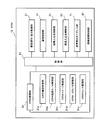
図3は、ATMの内部構成を示すブロック図である。
図3に示すATM10は、顧客操作・表示制御部21と、CRW(Card Reader Writer)制御部31と、通帳制御部41と、紙幣入出金制御部51と、硬貨入出金制御部61と、音声案内ガイダンス部71と、回線接続制御部81と、制御部91とを有している。
FIG. 3 is a block diagram showing the internal structure of the ATM.
3 includes a customer operation /
制御部91は、CPU(Central Processing Unit)等で構成され、記憶部(図示せず)に格納されているプログラムや、各種データに応じてATM10の各部を制御する。
顧客操作・表示制御部21は、タッチパネル20を介して利用者からの取引指示を受け取って制御部91に通知するとともに、制御部91からの指示にしたがってタッチパネル20の表示部に取引画面を表示する制御を行う。
The
The customer operation /
CRW制御部31は、カード読み取り部30を制御し、制御部91にしたがって、識別カードの磁気ストライプに記録された情報を読み出すとともに、必要に応じて書き込みを行う。また、取引終了時に、取引の明細票を識別カードと一緒に排出するとしてもよい。このようなCRW制御部31は、CRW搬送制御部31aと、CRW磁気R/W(Read/Write)制御部31bと、CRWイメージ制御部31cと、CRW ICR/W制御部31dと、CRWセンサ監視部31eと、を有する。CRW搬送制御部31aは、カード読み取り部30のカード挿入口から挿入された識別カードを装置内に取り込むとともに、取引終了時には識別カードを装置外に排出する。また、磁気ストライプの読み取り時、識別カードを識別カードの長手方向に搬送する制御を行う。CRW磁気R/W制御部31bは、識別カードの磁気ストライプに書き込まれた磁気情報の読み取りと、磁気ストライプへの磁気情報の書き込みとを制御する。CRWイメージ制御部31cは、識別カードのイメージ読み取りを制御する。CRW ICR/W制御部31dは、識別カードのICに記憶された情報の読み出しと、ICへの情報の書き込みを制御する。CRWセンサ監視部31eは、センサによって識別カードの位置を検出し、その位置情報の監視を行う。
The
通帳制御部41は、通帳読み取り部40を制御し、制御部91にしたがって、挿入された通帳を装置内に搬送し、通帳の磁気ストライプに記録された情報の読み込みを行う。また、制御部91の指示にしたがって通帳に取引記録を印字する。
The
紙幣入出金制御部51は、紙幣入出金部50を制御し、制御部91にしたがって紙幣の入出金を行う。出金指示では紙幣入出金部50に紙幣をセットし、入金指示では、紙幣入出金部50に利用者が投入した紙幣を装置内に取り込む。
The banknote deposit /
硬貨入出金制御部61は、硬貨入出金部60を制御し、制御部91にしたがって硬貨の入出金を行う。出金指示では硬貨入出金部60に硬貨をセットし、入金指示では硬貨入出金部60に利用者が投入した硬貨を装置内に取り込む。
The coin deposit /
音声案内ガイダンス部71は、制御部91の指示にしたがって利用者に対して音声による取引案内を行う。
回線接続制御部81は、通信路を介してホスト計算機(図示せず)に接続している。そして、制御部91の指示によってホスト計算機との間で取引情報を交換する。
The voice
The line
このような各部の制御により、ATM10における取引処理が行われる。
次に、ATM10に用いられる識別カードについて説明する。ATM10に用いられる識別カードは、JIS(Japanese Industrial Standard;日本工業規格)によって、磁気ストライプの貼り付け面、サイズ、貼り付け位置等が詳細に規定されている。また、このような識別カードには、ISO(International Organization for Standardization;国際標準化機構)仕様に準拠するタイプ1と、従来から銀行間で統一仕様として用いられてきたタイプ2とが規定されている。以下、タイプ1のISO仕様に準拠する磁気ストライプを磁気ストライプ(ISO)と表記し、タイプ2の磁気ストライプを磁気ストライプ(JIS2)と表記する。JIS規格では、識別カードのおもて面に磁気ストライプ(JIS2)を設け、裏面に磁気ストライプ(ISO)を設けることが規定されている。また、識別カードのおもて面には、エンボス文字と、ICチップを設けることもできる。エンボス文字はCRWイメージ制御部31cによって、イメージが読み取られる。ICチップはCRW ICR/W制御部31dによって、ICチップの情報読み出しと、書き込みが行われる。
The transaction process in ATM10 is performed by such control of each part.
Next, the identification card used for ATM10 is demonstrated. The identification card used in the
ここで、2つの異なるタイプの磁気ストライプについて説明する。タイプ1の磁気ストライプ(ISO)は、複数のトラックを備える高保磁力磁気ストライプで、耐消去性が高い。このため、磁気ストライプの磁気の減衰といった問題が起こりにくい。これに対し、タイプ2の磁気ストライプ(JIS2)は、1つのトラックから成り、磁気ストライプ(ISO)と比較して低保磁力であって耐消去性が低い。このため、磁気ストライプの磁気の減衰といった問題が生じやすい。しかしながら、タイプ2の磁気ストライプ(JIS2)は、国内金融機関等ですでに多く発行されており、このような状況に鑑み、磁気ストライプ(JIS2)の読み取り率向上が強く望まれている。
Here, two different types of magnetic stripes will be described. A
なお、ATM10に挿入される識別カードには、タイプ2の磁気ストライプ(JIS2)のみを搭載したものや、タイプ1の磁気ストライプ(ISO)のみを搭載したもの、両方の磁気ストライプを搭載したもの等がある。このため、ATM10は、すべてのタイプの識別カードに対応するように構成されている。
Note that the identification card inserted into the
次に、このような2種類の磁気ストライプを有する識別カードに対応するカード読み取り部30が備えるカード機構部について、図4を用いて説明する。図4は、カード機構部の構成の一例を示した概略図である。 Next, a card mechanism unit provided in the card reading unit 30 corresponding to an identification card having two types of magnetic stripes will be described with reference to FIG. FIG. 4 is a schematic diagram illustrating an example of the configuration of the card mechanism unit.
図4に示したカード機構部300は、識別カード200が搬送されるカード搬送路310と、識別カード200を搬送するカード搬送ローラ321、322と、識別カード200のおもて面の磁気ストライプ(JIS2)201を読み取る第1磁気ヘッド部(JIS2用)330と、裏面の磁気ストライプ(ISO用)を読み取る第2磁気ヘッド(ISO用)340と、を有し、識別カード200が備える磁気ストライプに記録される磁気情報の読み出し機能と書き込み機能を実現する。なお、図4に示した識別カード200の面はおもて面であり、タイプ2の磁気ストライプ(JIS2)201が形成されている。図示しない裏面には、タイプ1の磁気ストライプ(ISO)が形成されているとする。
The card mechanism unit 300 shown in FIG. 4 includes a card transport path 310 through which the identification card 200 is transported,
このような識別カード200に対応するため、カード機構部300は、タイプ2の磁気ストライプ(JIS2)201に対応する第1磁気ヘッド部(JIS2用)330と、タイプ1の磁気ストライプ(ISO)に対応する第2磁気ヘッド(ISO用)340とを有する。なお、図4では、わかりやすいように第1磁気ヘッド部(JIS2用)330をカード搬送路310から離した状態で示したが、実装時の第1磁気ヘッド部(JIS2用)330は、磁気ストライプ(JIS2)201に対向する位置に配置される。すなわち、第1磁気ヘッド部(JIS2用)330の磁気ヘッドと、第2磁気ヘッド(ISO用)340とは、識別カード200を挟んで対向する。
In order to cope with such an identification card 200, the card mechanism unit 300 includes a first magnetic head unit (for JIS 2) 330 corresponding to a
カード機構部300の各部について説明する。
カード搬送路310は、カード読み取り部30の挿入口から利用者が挿入した識別カード200を搬送する搬送路である。識別カード200は、識別カード200の長手方向を進行方向とし、カード搬送路310に沿ってカード機構部300内を搬送される。なお、図4の例では、識別カード200は、カード搬送路310を搬送されるとき、おもて面が上側を向き、磁気ストライプ(JIS2)201が、第1磁気ヘッド部(JIS2用)330に対向する。同時に、裏面の磁気ストライプ(ISO)が、第2磁気ヘッド(ISO用)340に対向する。
Each unit of the card mechanism unit 300 will be described.
The card transport path 310 is a transport path for transporting the identification card 200 inserted by the user from the insertion slot of the card reading unit 30. The identification card 200 is conveyed in the card mechanism 300 along the card conveyance path 310 with the longitudinal direction of the identification card 200 as the traveling direction. In the example of FIG. 4, when the identification card 200 is conveyed along the card conveyance path 310, the front surface faces upward, and the magnetic stripe (JIS2) 201 is the first magnetic head unit (for JIS2) 330. Opposite to. At the same time, the magnetic stripe (ISO) on the back surface faces the second magnetic head (for ISO) 340.
カード搬送ローラ321、322は、CRW搬送制御部31aにしたがって識別カード200を挟持しながらカード搬送路310内を搬送する。CRW搬送制御部31aは、第1磁気ヘッド部(JIS2用)330及び第2磁気ヘッド(ISO用)340による磁気ストライプの磁気データ読み出しの際には、カード搬送ローラ321、322を制御し、CRW磁気R/W制御部31bの指示に応じて一定の速度で識別カード200を搬送する。これにより、磁気ストライプ(JIS2)201と、図示しない磁気ストライプ(ISO)とは、一定の速度で第1磁気ヘッド部(JIS2用)330と、第2磁気ヘッド(ISO用)340とが配置される位置を通過する。
The
第1磁気ヘッド部(JIS2用)330は、CRW磁気R/W制御部31bにしたがって、第1磁気ヘッド部(JIS2用)330の磁気ヘッドが、磁気ストライプ(JIS2)201に書き込まれている磁気データを読み出す。磁気ストライプ(JIS2)201は、CRW搬送制御部31aが制御するカード搬送ローラ321、322によって一定の速度で第1磁気ヘッド部(JIS2用)330が配置される位置を通過する。第1磁気ヘッド部(JIS2用)330は、通過する磁気ストライプ(JIS2)201に記録されている磁気データを順次読み取る。磁気データが正常に読み取れなかったときは、第1磁気ヘッド部(JIS2用)330の磁気ヘッドの位置を磁気ストライプ(JIS2用)201の幅方向にシフトして再度読み取りを行うリトライ処理を実行する。リトライ処理は、磁気データが正常に読み取れるか、リトライ回数が予め決められた最大リトライ回数に到達するまで行われる。磁気ストライプ(JIS2用)201は、その幅方向では同じ値を読み取ることができるので、幅方向に磁気ヘッドをシフトして読み取りを行うことにより、読み取り率を向上させることができる。
The first magnetic head unit (for JIS2) 330 is a magnetic field in which the magnetic head of the first magnetic head unit (for JIS2) 330 is written in the magnetic stripe (JIS2) 201 in accordance with the CRW magnetic R /
第2磁気ヘッド(ISO用)340は、CRW磁気R/W制御部31bにしたがって、第2磁気ヘッド(ISO用)340が、磁気ストライプ(ISO)に書き込まれている磁気データを読み出す。読み取りは、第1磁気ヘッド部(JIS2用)330による磁気ストライプ(JIS2)201の読み取りと同時に行われてもよい。磁気ストライプ(ISO)は、CRW搬送制御部31aが制御するカード搬送ローラ321、322によって一定の速度で第2磁気ヘッド(ISO用)340が配置される位置を通過する。第2磁気ヘッド(ISO用)340は、通過する磁気ストライプ(ISO)に記録されている磁気データを順次読み取る。第2磁気ヘッド(ISO用)340の位置は固定であり、読み取りが正常に行われなかったときは、第2磁気ヘッド(ISO用)340は同じ位置で、読み取りをリトライする。なお、上記のように、磁気ストライプ(ISO)は、高保磁力の磁気ストライプであり、耐消去性が高く、磁気の減衰が起こりにくい。また、ISOでは、磁気ストライプを幅方向に分割した複数のトラックを有することが定義されており、1つのトラックの幅が磁気ストライプ(JIS2)201に比べて狭い。このため、第2磁気ヘッド(ISO用)340の幅方向の位置をシフトさせて再読み取りを行っても、第1磁気ヘッド部(JIS2用)330と比較し、読み取り率の向上への寄与は低い。
The second magnetic head (for ISO) 340 reads the magnetic data written in the magnetic stripe (ISO) by the second magnetic head (for ISO) 340 in accordance with the CRW magnetic R /
次に、第1磁気ヘッド部(JIS2用)330について、図5を用いて説明する。図5は、第1磁気ヘッド部の構成の一例を示した概略図である。
図5に示した第1磁気ヘッド部(JIS2用)330は、第1磁気ヘッド(JIS2用)331と、スクリュー軸332及び駆動プーリー333を備える磁気ヘッドシフト部と、を有する。
Next, the first magnetic head unit (for JIS 2) 330 will be described with reference to FIG. FIG. 5 is a schematic view showing an example of the configuration of the first magnetic head unit.
The first magnetic head unit (for JIS 2) 330 shown in FIG. 5 includes a first magnetic head (for JIS 2) 331, and a magnetic head shift unit including a
第1磁気ヘッド(JIS2用)331は、磁気ストライプ(JIS2)201の幅方向に移動するキャリッジによって保持されている。そして、磁気ヘッドシフト部によって磁気ストライプ(JIS2)201の幅方向にシフトし、磁気ストライプ(JIS2)201の磁気データの読み取りを行う。シフトする範囲は、磁気ストライプ(JIS2)201の幅方向の上端201aに対向する位置と、下端201bに対向する位置との間になる。 The first magnetic head (for JIS 2) 331 is held by a carriage that moves in the width direction of the magnetic stripe (JIS 2) 201. Then, the magnetic head shift unit shifts in the width direction of the magnetic stripe (JIS 2) 201, and reads the magnetic data of the magnetic stripe (JIS 2) 201. The shift range is between a position facing the upper end 201a in the width direction of the magnetic stripe (JIS 2) 201 and a position facing the lower end 201b.
磁気ヘッドシフト部は、キャリッジと歯合するスクリュー軸332と、スクリュー軸332を回転駆動する駆動プーリー333とを有する。スクリュー軸332は、カード搬送路310上を搬送される識別カード200の幅方向に延在し、第1磁気ヘッド(JIS2用)331を保持するキャリッジと歯合するらせん状の溝(スクリュー)を有する。駆動プーリー333は、スクリュー軸332の一端に設けられ、図示しない駆動回路からの駆動信号を受けて回転し、スクリュー軸332を回転させる。
The magnetic head shift unit includes a
このような構成の第1磁気ヘッド部(JIS2用)330では、CRW磁気R/W制御部31bにしたがって駆動プーリー333が駆動され、スクリュー軸332が回転する。これにより、スクリュー軸332と歯合するキャリッジが、スクリュー軸332上を移動する。これに応じて、キャリッジが保持する第1磁気ヘッド(JIS2用)331は、キャリッジと同様にスクリュー軸332上を移動する。図5に示したように、ヘッド移動方向は、磁気ストライプ(JIS2)201の幅方向であり、カード搬送方向と直交する。
In the first magnetic head unit (for JIS2) 330 having such a configuration, the drive pulley 333 is driven according to the CRW magnetic R /
CRW磁気R/W制御部31bは、第1磁気ヘッド(JIS2用)331を通常の読み取り位置、例えば、磁気ストライプ(JIS2)201の幅方向の中央部に配置し、識別カード200を識別カード200の長手方向に搬送して磁気データを読み取る。正常に読み取れたときは、読み取れた磁気データを出力する。正常に読み取れなかったときは、磁気ヘッドシフト部を駆動し、第1磁気ヘッド(JIS2用)331の位置を、例えば、幅方向の中央部から幅方向の一方端側にシフトし、再度磁気データの読み取りを行う。
The CRW magnetic R /
磁気データが正常に読み取れなったときの第1磁気ヘッド(JIS2用)331のシフト位置は、磁気ストライプ(JIS2)201の読み取り処理を開始してからまだ読み取りを行っていない幅方向の位置であればよい。しかしながら、磁気の一部減衰や、ゴミの付着、傷などはある範囲内で発生している場合が多く、シフト前の位置とシフト後の位置との間隔が狭いと、シフト後の位置も磁気の一部減衰などの範囲であることがある。この場合、再度読み取りを行っても、正常に読み取ることができない。そこで、ある程度離れた位置にシフトさせて再読み取りを行うことが望ましい。 The shift position of the first magnetic head (for JIS2) 331 when the magnetic data cannot be read normally is a position in the width direction where the reading process of the magnetic stripe (JIS2) 201 has not been performed yet. That's fine. However, partial attenuation of magnetism, dust adhesion, and scratches often occur within a certain range. If the distance between the position before the shift and the position after the shift is narrow, the position after the shift is also magnetic. There may be a range such as partial attenuation of. In this case, even if it reads again, it cannot read normally. Therefore, it is desirable to perform re-reading by shifting the position to a certain distance.
例えば、磁気ストライプ(JIS2)201の幅方向の中央部を中心として、一方端側と、他方端側に交互に第1磁気ヘッド(JIS2用)331をシフトさせて、読み取りをリトライすることが考えられる。一例を挙げると、図5に示した磁気ストライプ(JIS2)201の一方端を上端201aとし、他方端を下端201bとして、最初に磁気ストライプ(JIS2)201の幅方向の中央部に第1磁気ヘッド(JIS2用)331を配置し、読み取りを行うとする。中央部で読み取れなかったときは、中央部から上端201a側に第1磁気ヘッド(JIS2用)331の位置をシフトし、シフトした位置で読み取りを行う。上端201a側において磁気データが正常に読み取れなかったときは、中央部より下端201b側に第1磁気ヘッド(JIS2用)331の位置をシフトし、再度磁気データの読み取りを行う。予め決められた最大リトライ回数に到達するまで第1磁気ヘッド(JIS2用)331の位置をシフトさせて、磁気データの読み取りを行う。 For example, the first magnetic head (for JIS 2) 331 may be alternately shifted from one end side to the other end side around the central portion in the width direction of the magnetic stripe (JIS 2) 201 to retry reading. It is done. As an example, first magnetic head (JIS2) 201 shown in FIG. 5 has one end as upper end 201a and the other end as lower end 201b, and first magnetic head at the center in the width direction of magnetic stripe (JIS2) 201 first. Assume that (for JIS2) 331 is arranged and reading is performed. If reading is not possible at the center, the position of the first magnetic head (for JIS2) 331 is shifted from the center toward the upper end 201a, and reading is performed at the shifted position. If the magnetic data cannot be read normally on the upper end 201a side, the position of the first magnetic head (for JIS2) 331 is shifted from the center to the lower end 201b side, and the magnetic data is read again. The position of the first magnetic head (for JIS2) 331 is shifted until the predetermined maximum number of retries is reached, and magnetic data is read.
このように第1磁気ヘッド(JIS2用)331の位置を幅方向にシフトすることによって、さらに読み取り率を向上できる。
このような構成のカード機構部300を制御してCRW制御部31が行うカード読み取り処理について図6を用いて説明する。図6は、カード読み取り位置の一例を示した図である。図6の例では、2回のリトライを行うとしている。
Thus, the reading rate can be further improved by shifting the position of the first magnetic head (for JIS2) 331 in the width direction.
A card reading process performed by the
CRW制御部31は、カード機構部300に取り込まれた識別カード200をカード搬送ローラ321、322によって挟持し、カード搬送路310に沿って識別カード200の長手方向に搬送する。このとき、識別カード200は、一定の速度で搬送される。識別カード200のおもて面の磁気ストライプ(JIS2)201に記録された磁気データは、識別カード200が第1磁気ヘッド部(JIS2用)330の第1磁気ヘッド(JIS2用)331を通過する際に読み取られる。同時に、識別カード200の裏面の磁気ストライプ(ISO)に記録された磁気データは、識別カード200が第2磁気ヘッド(ISO用)340を通過する際に読み取られる。
The
このとき、第1磁気ヘッド(JIS2用)331を、図6に示した1回目読み取り位置211に対向する位置に配置して磁気ストライプ(JIS2)201の磁気データを読み取る。これにより、1回目読み取り位置211に対応する斜線で示した領域において磁気データが読み取られる。1回目読み取り位置211において正常に読み取りができなかったときは、CRW制御部31は磁気ヘッドシフト部の駆動プーリー333を駆動し、第1磁気ヘッド(JIS2用)331の位置を磁気ストライプ(JIS2)201の幅方向にシフトする。図6に示した2回目読み取り位置212では、1回目読み取り位置211より上端側に第1磁気ヘッド(JIS2用)331をシフトし、読み取りを行う。これにより、2回目読み取り位置212に対応する斜線で示した領域において磁気データが読み取られる。2回目読み取り位置212において正常に読み取りができなかったときは、CRW制御部31は磁気ヘッドシフト部の駆動プーリー333を駆動し、第1磁気ヘッド(JIS2用)331の位置を磁気ストライプ(JIS2)201の幅方向にシフトする。図6に示した3回目読み取り位置213では、1回目読み取り位置211より下端側に第1磁気ヘッド(JIS2用)331をシフトし、読み取りを行う。
At this time, the first magnetic head (for JIS2) 331 is arranged at a position opposite to the first reading position 211 shown in FIG. 6 to read the magnetic data of the magnetic stripe (JIS2) 201. As a result, magnetic data is read in the hatched area corresponding to the first reading position 211. When the reading cannot be performed normally at the first reading position 211, the
図6に示した例では、磁気ストライプ(JIS2)201の磁気データが、幅方向の中央部(1回目読み取り位置211)において正常に読み取れなかったときは、中央部の上側(2回目読み取り位置212)、中央部の下側(3回目読み取り位置213)と、幅方向に位置を変えてリトライを行う。なお、図6に示した例では、3回目読み取り位置213において正常に読み取りができず、リトライ回数が最大リトライ回数に到達していないときは、再度、中央部の上側に第1磁気ヘッド(JIS2用)331をシフトさせる。 In the example shown in FIG. 6, when the magnetic data of the magnetic stripe (JIS2) 201 cannot be normally read in the central portion (first reading position 211) in the width direction, the upper side (second reading position 212) of the central portion. ) Retry is performed by changing the position in the width direction from the lower side of the central portion (third reading position 213). In the example shown in FIG. 6, when the reading cannot be normally performed at the third reading position 213 and the number of retries has not reached the maximum number of retries, the first magnetic head (JIS2) is again placed above the center portion. For) 331 is shifted.
このように、第1磁気ヘッド(JIS2用)331の位置をシフトして読み取りをリトライすることにより、磁気ストライプ(JIS2)201の一部の磁気が減衰した場合であっても、磁気ストライプ(JIS2)201の磁気データを読み出すことができる。 As described above, even if a part of the magnetic stripe (JIS2) 201 is attenuated by shifting the position of the first magnetic head (for JIS2) 331 and retrying reading, the magnetic stripe (JIS2) ) 201 magnetic data can be read.
読み取り動作について、一例を挙げて説明する。図7は、正常な識別カードと一部の磁気が減衰した識別カードとを示した図である。図7では、磁気ストライプ(JIS2)221、231内の長手方向に直交する線によって囲まれた領域が1つの磁気データの領域を表しているとする。隣接する磁気データの領域との間の線が消えている箇所が磁気の減衰部232であり、磁気データが正しく読み取れない領域であるとする。 The reading operation will be described with an example. FIG. 7 is a diagram showing a normal identification card and an identification card in which some magnetism is attenuated. In FIG. 7, it is assumed that a region surrounded by a line perpendicular to the longitudinal direction in the magnetic stripes (JIS 2) 221 and 231 represents one magnetic data region. It is assumed that the portion where the line between the adjacent magnetic data areas disappears is the magnetic attenuation unit 232, and the magnetic data cannot be read correctly.
図7の(1)に示した磁気減衰が生じていない識別カード(正常)220では、磁気ストライプ(JIS2)221の磁気データは正常であり、磁気ストライプ(JIS2)221の幅方向のいずれの場所を読み取り位置としても磁気データを読み取ることができる。したがって、幅方向の中央部である1回目読み取り位置211に第1磁気ヘッド(JIS2用)331を配置して読み取りを行ったとき、正常に読み取りを終了することができる。 In the identification card (normal) 220 with no magnetic attenuation shown in (1) of FIG. 7, the magnetic data of the magnetic stripe (JIS2) 221 is normal, and any location in the width direction of the magnetic stripe (JIS2) 221 The magnetic data can be read even if is set as the reading position. Therefore, when reading is performed with the first magnetic head (for JIS2) 331 placed at the first reading position 211, which is the central portion in the width direction, the reading can be completed normally.
一方、図7の(2)に示した一部に磁気が減衰した識別カード(磁気減衰)230では、中央部から上部にかけて一部の磁気が減衰した磁気の減衰部232がある。したがって、1回目読み取り位置211における読み取りと、2回目読み取り位置212における読み取りでは、磁気データを正しく読み取ることができない。しかし、3回目読み取り位置213における読み取りでは、磁気データを正しく読み取ることができる。 On the other hand, in the identification card (magnetic attenuation) 230 in which a part of the magnetism is attenuated as shown in (2) of FIG. 7, there is a magnetic attenuation part 232 in which a part of the magnetism is attenuated from the central part to the upper part. Therefore, magnetic data cannot be read correctly by reading at the first reading position 211 and reading at the second reading position 212. However, magnetic data can be read correctly in the reading at the third reading position 213.
このように、磁気ストライプの読み取り位置をシフトさせて磁気データの読み取りをリトライすることにより、読み取り率を向上させることが可能となる。また、磁気ヘッドをシフトさせる構成であるため、おもて面と裏面とに磁気ストライプが形成されている場合であっても、読み取り位置をシフトしてのリトライ読み取りを実行する磁気ヘッドのみに磁気ヘッドシフト部を備える構成とすればよい。このため、カード搬送路の幅を広げることなく、一方だけに磁気ヘッドシフト部を設ければよいため、装置の大型化やコスト上昇を抑えることができる。 As described above, the reading rate can be improved by retrying the reading of the magnetic data by shifting the reading position of the magnetic stripe. In addition, since the magnetic head is shifted, even when magnetic stripes are formed on the front and back surfaces, only the magnetic head that performs retry reading with the reading position shifted is magnetic. What is necessary is just to set it as the structure provided with a head shift part. For this reason, since it is only necessary to provide the magnetic head shift part on one side without increasing the width of the card transport path, it is possible to suppress an increase in size and cost of the apparatus.
なお、上記の説明では、読み取り位置を中央部、上、下とシフトさせるとしたが、シフトする位置及びシフト順は任意に設定することができる。また、リトライ回数も任意に設定することができる。 In the above description, the reading position is shifted to the center, up, and down, but the position to shift and the shift order can be arbitrarily set. Also, the number of retries can be set arbitrarily.
次に、CRW制御部31によるカード読み取り処理について図8を用いて説明する。図8は、カード読み取り処理の手順を示したフローチャートである。なお、図8に示すカード読み取り処理は、磁気ストライプ(JIS2)201の読み取り処理を示している。なお、磁気ストライプ(ISO)については、従来と同様に、位置が固定の第2磁気ヘッド(ISO用)340によって読み取りを行うとする。
Next, card reading processing by the
識別カード200がATM10に挿入されたことを検知し、CRW制御部31がカード読み取り処理を開始する。以下の読み取り処理は、CRW制御部31にしたがって、CRW搬送制御部31aとCRW磁気R/W制御部31bとが行う。
Upon detecting that the identification card 200 has been inserted into the
[ステップS01] 1回目の磁気データ読み取りを行う。1回目の磁気データ読み取りは、第1磁気ヘッド(JIS2用)331が通常位置に配置された状態で行われる。ここでは、通常位置を、磁気ストライプ(JIS2)201が形成される領域の幅方向の中央部とする。第1磁気ヘッド(JIS2用)331が磁気ストライプ(JIS2)201の幅方向の中央に位置した状態で、カード搬送ローラ321、322によって識別カード200が磁気ストライプ(JIS2)201の長手方向に搬送される。第1磁気ヘッド(JIS2用)331は、磁気ストライプ(JIS2)201に密着し、通過する磁気ストライプ(JIS2)201に記録される磁気データを順次読み取る。
[Step S01] The first magnetic data reading is performed. The first magnetic data reading is performed in a state where the first magnetic head (for JIS2) 331 is disposed at the normal position. Here, the normal position is the center in the width direction of the region where the magnetic stripe (JIS 2) 201 is formed. With the first magnetic head (for JIS2) 331 positioned at the center of the magnetic stripe (JIS2) 201 in the width direction, the identification card 200 is conveyed in the longitudinal direction of the magnetic stripe (JIS2) 201 by the
[ステップS02] 第1磁気ヘッド(JIS2用)331による磁気データの読み取りは正常であったか否かを判定する。磁気データの読み取りが正常に終了したときは、処理をステップS03に進め、磁気データの読み取りが正常に終了しなかったときは、処理をステップS04に進める。 [Step S02] It is determined whether or not reading of magnetic data by the first magnetic head (for JIS2) 331 is normal. When the reading of magnetic data is normally completed, the process proceeds to step S03. When the reading of magnetic data is not normally completed, the process proceeds to step S04.
[ステップS03] 磁気データの読み取りが正常に終了したときは、カード読み取り正常とし、処理を終了する。
[ステップS04] 磁気データの読み取りが正常に終了しなかったときは、第1磁気ヘッド(JIS2用)331による読み取り位置を変更する。磁気ヘッドシフト部を動作させて、これまでの読み取り処理で読み取りを行っていない位置に第1磁気ヘッド(JIS2用)331を移動させる。
[Step S03] When the reading of the magnetic data is normally completed, the card reading is regarded as normal and the process is terminated.
[Step S04] When the reading of the magnetic data is not normally completed, the reading position by the first magnetic head (for JIS2) 331 is changed. The magnetic head shift unit is operated to move the first magnetic head (for JIS 2) 331 to a position where reading has not been performed in the reading process so far.
[ステップS05] 第1磁気ヘッド(JIS2用)331がステップS04で決定した位置に配置された状態で、カード搬送ローラ321、322によって識別カード200が磁気ストライプ(JIS2)201の長手方向に搬送される。第1磁気ヘッド(JIS2用)331は、磁気ストライプ(JIS2)201に密着し、通過する磁気ストライプ(JIS2)201に記録される磁気データを順次読み取る。
[Step S05] With the first magnetic head (for JIS2) 331 disposed at the position determined in step S04, the identification card 200 is conveyed in the longitudinal direction of the magnetic stripe (JIS2) 201 by the
[ステップS06] 第1磁気ヘッド(JIS2用)331によって磁気データの読み取りが正常であったか否かを判定する。磁気データが正常に読み取れたときは、処理をステップS03に進め、磁気データが正常に読み取れなかったときは、処理をステップS07に進める。 [Step S06] The first magnetic head (for JIS 2) 331 determines whether or not the reading of magnetic data is normal. If the magnetic data can be read normally, the process proceeds to step S03. If the magnetic data cannot be read normally, the process proceeds to step S07.
[ステップS07] 磁気データが正常に読み取れなかったNG回数を1増加し、予め決められたリトライ回数の上限値nと比較してNG回数がn回未満であるかどうか判定する。n回未満であれば、処理をステップS04に進め、n回に達していれば処理をステップS08に進める。 [Step S07] The number of NGs in which the magnetic data could not be read normally is increased by 1, and compared with a predetermined upper limit n of the number of retries, it is determined whether the number of NGs is less than n. If it is less than n times, the process proceeds to step S04, and if it has reached n times, the process proceeds to step S08.
[ステップS08] 磁気データの読み取りに失敗した回数が規定値(n回)に達したので、カード読み取りエラーとして処理を終了する。
このような手順が実行されることにより、磁気ストライプの磁気データが、予め決められた通常位置で正常に読み取れなかったときは、磁気ストライプの幅方向に磁気ヘッドをシフトさせリトライが行われる。これにより、磁気ストライプの一部に磁気減衰、傷、汚れ等が生じていた場合であっても、磁気データの読み取りが成功する確率を高くすることができる。この結果、磁気ストライプに記録された磁気データの読み取り率を上げ、利用者の利便性を向上することができる。
[Step S08] Since the number of failed magnetic data readings has reached a specified value (n times), the process ends as a card reading error.
By executing such a procedure, when the magnetic data of the magnetic stripe cannot be read normally at a predetermined normal position, the magnetic head is shifted in the width direction of the magnetic stripe and a retry is performed. As a result, even when magnetic attenuation, scratches, dirt, etc. occur in a part of the magnetic stripe, the probability of successful reading of magnetic data can be increased. As a result, it is possible to increase the reading rate of the magnetic data recorded on the magnetic stripe and improve the convenience for the user.
なお、上記の処理機能は、コンピュータによって実現することができる。その場合、印字装置が有すべき機能の処理内容を記述したプログラムが提供される。そのプログラムをコンピュータで実行することにより、上記処理機能がコンピュータ上で実現される。処理内容を記述したプログラムは、コンピュータで読み取り可能な記録媒体に記録しておくことができる。コンピュータで読み取り可能な記録媒体としては、磁気記憶装置、光ディスク、光磁気記録媒体、半導体メモリなどがある。磁気記憶装置には、ハードディスク装置(HDD;Hard Disk Drive)、フレキシブルディスク(FD)、磁気テープなどがある。光ディスクには、DVD(Digital Versatile Disc)、DVD−RAM(Random Access Memory)、CD−ROM(Compact Disc Read Only Memory)、CD−R(Recordable)/RW(ReWritable)などがある。光磁気記録媒体には、MO(Magneto-Optical disk)などがある。 The above processing functions can be realized by a computer. In that case, a program describing the processing contents of the functions that the printing apparatus should have is provided. By executing the program on a computer, the above processing functions are realized on the computer. The program describing the processing contents can be recorded on a computer-readable recording medium. Examples of the computer-readable recording medium include a magnetic storage device, an optical disk, a magneto-optical recording medium, and a semiconductor memory. Examples of the magnetic storage device include a hard disk device (HDD), a flexible disk (FD), and a magnetic tape. Examples of the optical disc include a DVD (Digital Versatile Disc), a DVD-RAM (Random Access Memory), a CD-ROM (Compact Disc Read Only Memory), and a CD-R (Recordable) / RW (ReWritable). Magneto-optical recording media include MO (Magneto-Optical disk).
プログラムを流通させる場合には、たとえば、そのプログラムが記録されたDVD、CD−ROMなどの可搬型記録媒体が販売される。また、プログラムをサーバコンピュータの記憶装置に格納しておき、ネットワークを介して、サーバコンピュータから他のコンピュータにそのプログラムを転送することもできる。 When distributing the program, for example, portable recording media such as a DVD and a CD-ROM in which the program is recorded are sold. It is also possible to store the program in a storage device of a server computer and transfer the program from the server computer to another computer via a network.
プログラムを実行するコンピュータは、たとえば、可搬型記録媒体に記録されたプログラムもしくはサーバコンピュータから転送されたプログラムを、自己の記憶装置に格納する。そして、コンピュータは、自己の記憶装置からプログラムを読み取り、プログラムにしたがった処理を実行する。なお、コンピュータは、可搬型記録媒体から直接プログラムを読み取り、そのプログラムにしたがった処理を実行することもできる。また、コンピュータは、ネットワークを介して接続されたサーバコンピュータからプログラムが転送されるごとに、逐次、受け取ったプログラムにしたがった処理を実行することもできる。 The computer that executes the program stores, for example, the program recorded on the portable recording medium or the program transferred from the server computer in its own storage device. Then, the computer reads the program from its own storage device and executes processing according to the program. The computer can also read the program directly from the portable recording medium and execute processing according to the program. In addition, each time a program is transferred from a server computer connected via a network, the computer can sequentially execute processing according to the received program.
また、上記の処理機能の少なくとも一部を、DSP(Digital Signal Processor)、ASIC(Application Specific Integrated Circuit)、PLD(Programmable Logic Device)などの電子回路で実現することもできる。 In addition, at least a part of the above processing functions can be realized by an electronic circuit such as a DSP (Digital Signal Processor), an ASIC (Application Specific Integrated Circuit), or a PLD (Programmable Logic Device).
1 磁気情報読み取り装置
2 カード
2a カード(平面)
2b カード(断面)
3 磁気ストライプ
10 ATM
11 カード搬送部
12 磁気ヘッド
13 磁気ヘッドシフト部
14 読み取り制御部
20 タッチパネル
21 顧客操作・表示制御部
30 カード読み取り部
31 CRW制御部
31a CRW搬送制御部
31b CRW磁気R/W制御部
31c CRWイメージ制御部
31d CRW ICR/W制御部
31e CRWセンサ監視部
40 通帳読み取り部
41 通帳制御部
50 紙幣入出金部
51 紙幣入出金制御部
60 硬貨入出金部
61 硬貨入出金制御部
71 音声案内ガイダンス部
81 回線接続制御部
91 制御部
200 識別カード
201 磁気ストライプ(JIS2)
201a 上端
201b 下端
211 1回目読み取り位置
212 2回目読み取り位置
213 3回目読み取り位置
220 識別カード(正常)
221 磁気ストライプ(JIS2)
230 識別カード(磁気減衰)
231 磁気ストライプ(JIS2)
232 減衰部
300 カード機構部
310 カード搬送路
321、322 カード搬送ローラ
330 第1磁気ヘッド部(JIS2用)
331 第1磁気ヘッド(JIS2用)
332 スクリュー軸
333 駆動プーリー
340 第2磁気ヘッド(ISO用)
1
2b card (cross section)
3
DESCRIPTION OF
201a Upper end 201b Lower end 211 First reading position 212 Second reading position 213 Third reading position 220 Identification card (normal)
221 Magnetic stripe (JIS2)
230 Identification card (magnetic attenuation)
231 Magnetic stripe (JIS2)
232 Attenuating section 300 Card mechanism section 310
331 First magnetic head (for JIS2)
332 Screw shaft 333 Drive pulley 340 Second magnetic head (for ISO)
Claims (4)
前記第2の磁気ストライプと比較して保磁力の低い前記第1の磁気ストライプに対応する前記第1の磁気ヘッドに対して設けられ、前記トラックの長手方向と直交する幅方向に前記第1の磁気ヘッドの読み取り位置をシフトする磁気ヘッドシフト部と、
所定の位置に配置した前記第1の磁気ヘッドによる対象トラックの前記第1の磁気情報の読み取りにおいて、前記第1の磁気情報が正常に読み取れなかったときは、前記磁気ヘッドシフト部によって前記対象トラックの幅内で前記幅方向に前記読み取り位置をシフトし、シフトした前記読み取り位置において前記第1の磁気ヘッドによる前記第1の磁気情報の読み取りを再度行い、所定のリトライ回数と、前記対象トラックについて前記読み取り位置をシフトして行った前記第1の磁気情報の読み取り回数とを比較し、前記読み取り回数が、前記所定のリトライ回数に到達していないときは、前記読み取り位置をシフトして前記第1の磁気情報の読み取りを再度行い、前記所定のリトライ回数に到達していたときは、前記第1の磁気情報の読み取りを終了して前記第1の磁気情報の読み取りエラーとする読み取り制御部と、
を有し、
前記読み取り制御部は、1回目の読み取りでは、前記第1の磁気ヘッドを前記幅方向の中央部の第1の位置に配置して前記第1の磁気情報の読み取りを行い、
前記第1の位置で前記第1の磁気情報が正常に読み取れなかったときは、前記第1の磁気ヘッドを前記幅方向の一方端にシフトした第2の位置で前記第1の磁気情報の読み取りを行い、
前記第2の位置で前記第1の磁気情報が正常に読み取れなかったときは、前記第1の磁気ヘッドを前記幅方向の他方端にシフトした第3の位置で前記第1の磁気情報の読み取りを行い、
前記第1の磁気情報が正常に読み取れるか、または、前記対象トラックについて前記読み取り位置をシフトして行った前記第1の磁気情報の読み取り回数が、前記所定のリトライ回数に到達するまで、前記読み取り位置について、前記幅方向へのシフトを繰り返す、
磁気情報読み取り装置。 Longitudinally formed in a strip track was closed, respectively, with respect to a second magnetic stripe formed on the back surface of the first magnetic stripe formed on the front surface to be read of the card the card, the A first magnetic head for reading first magnetic information written in the first magnetic stripe and a second magnetic head for reading second magnetic information written in the second magnetic stripe ;
Provided with respect to the first magnetic head corresponding to the first magnetic stripe having a lower coercive force than the second magnetic stripe, and the first magnetic head in the width direction perpendicular to the longitudinal direction of the track . A magnetic head shift unit for shifting the reading position of the magnetic head;
In the reading of the first magnetic information of the target track by the first magnetic head arranged at a predetermined position, if the first magnetic information cannot be read normally, the magnetic head shift unit causes the target track to be read. shifting the reading position in the width direction within a width of, performed at the reading position obtained by shifting the reading of the first magnetic information by the first magnetic head again, and a predetermined number of retries, for the target track comparing the number of reads said first magnetic information was performed by shifting the reading position, the reading number of times, when not reached the predetermined number of retries, the shifts the reading position first It reads the first magnetic information again, when it has reached the predetermined number of retries, reading of the first magnetic information A read controller which exit is taken to a reading error of the first magnetic information,
Have
The reading control unit, in the first scan, and positioning the first magnetic head in the first position of the central portion in the width direction to read said first magnetic information,
Reading of the when the first magnetic information is not normally read in a first position, the first magnetic information said first magnetic head in the second position shifted to one end of the width direction And
Reading of the when the first magnetic information is not normally read in the second position, the first magnetic information said first magnetic head in the third position shifted to the other end in the width direction And
The reading is performed until the first magnetic information can be read normally, or the number of readings of the first magnetic information performed by shifting the reading position for the target track reaches the predetermined number of retries. For the position, the shift in the width direction is repeated.
Magnetic information reader.
前記読み取り制御部は、前記駆動プーリーを駆動して前記キャリッジを前記スクリュー軸の延在方向に移動させ、前記磁気ヘッドを前記幅方向にシフトする、
請求項1に記載の磁気情報読み取り装置。 The magnetic head shift unit includes a screw shaft that extends in the width direction and meshes with a carriage that holds the magnetic head, and a drive pulley that rotates the screw shaft.
The read control unit drives the drive pulley to move the carriage in the extending direction of the screw shaft, and shifts the magnetic head in the width direction.
The magnetic information reading apparatus according to claim 1.
長手方向に帯状に形成されたトラックをそれぞれ有し、読み取り対象のカードのおもて面に形成される第1の磁気ストライプと前記カードの裏面に形成される第2の磁気ストライプとに対する、前記第1の磁気ストライプに書き込まれた第1の磁気情報を読み取る第1の磁気ヘッド及び前記第2の磁気ストライプに書き込まれた第2の磁気情報を読み取る第2の磁気ヘッドを所定の位置に配置し、
前記第2の磁気ストライプと比較して保磁力の低い前記第1の磁気ストライプに対応する前記第1の磁気ヘッドに対して、前記所定の位置に配置した前記第1の磁気ヘッドによる対象トラックの前記第1の磁気情報の読み取りにおいて、前記第1の磁気情報が正常に読み取れなかったときは、前記トラックの長手方向と直交する幅方向に前記第1の磁気ヘッドの読み取り位置をシフトする磁気ヘッドシフト部によって前記対象トラックの幅内で前記幅方向に前記読み取り位置をシフトし、
シフトした前記読み取り位置において前記第1の磁気ヘッドによる前記第1の磁気情報の読み取りを再度行い、所定のリトライ回数と、前記対象トラックについて前記読み取り位置をシフトして行った前記第1の磁気情報の読み取り回数とを比較し、前記読み取り回数が、前記所定のリトライ回数に到達していないときは、前記読み取り位置をシフトして前記第1の磁気情報の読み取りを再度行い、前記所定のリトライ回数に到達していたときは、前記第1の磁気情報の読み取りを終了して前記第1の磁気情報の読み取りエラーとし、
1回目の読み取りでは、前記第1の磁気ヘッドを前記幅方向の中央部の第1の位置に配置して前記第1の磁気情報の読み取りを行い、
前記第1の位置で前記第1の磁気情報が正常に読み取れなかったときは、前記第1の磁気ヘッドを前記幅方向の一方端にシフトした第2の位置で前記第1の磁気情報の読み取りを行い、
前記第2の位置で前記第1の磁気情報が正常に読み取れなかったときは、前記第1の磁気ヘッドを前記幅方向の他方端にシフトした第3の位置で前記第1の磁気情報の読み取りを行い、
前記第1の磁気情報が正常に読み取れるか、または、前記対象トラックについて前記読み取り位置をシフトして行った前記第1の磁気情報の読み取り回数が、前記所定のリトライ回数に到達するまで、前記読み取り位置について、前記幅方向へのシフトを繰り返す、
磁気情報読み取り方法。 Computer
Longitudinally formed in a strip track was closed, respectively, with respect to a second magnetic stripe formed on the back surface of the first magnetic stripe formed on the front surface to be read of the card the card, the A first magnetic head for reading first magnetic information written in the first magnetic stripe and a second magnetic head for reading second magnetic information written in the second magnetic stripe are arranged at predetermined positions. And
With respect to the first magnetic head corresponding to the first magnetic stripe having a coercive force lower than that of the second magnetic stripe, the target track by the first magnetic head arranged at the predetermined position When reading the first magnetic information, if the first magnetic information cannot be read normally, the magnetic head shifts the reading position of the first magnetic head in the width direction orthogonal to the longitudinal direction of the track. Shifting the reading position in the width direction within the width of the target track by a shift unit,
In shifted the reading position to read the first magnetic information by the first magnetic head again, said first magnetic information was performed by shifting a predetermined number of retries, the reading position for the target track If the read count does not reach the predetermined retry count, the read position is shifted, the first magnetic information is read again, and the predetermined retry count is set. The reading of the first magnetic information is terminated and an error in reading the first magnetic information occurs,
In the first reading, the first magnetic head is arranged at the first position in the center in the width direction to read the first magnetic information,
Reading of the when the first magnetic information is not normally read in a first position, the first magnetic information said first magnetic head in the second position shifted to one end of the width direction And
Reading of the when the first magnetic information is not normally read in the second position, the first magnetic information said first magnetic head in the third position shifted to the other end in the width direction And
The reading is performed until the first magnetic information can be read normally, or the number of readings of the first magnetic information performed by shifting the reading position for the target track reaches the predetermined number of retries. For the position, the shift in the width direction is repeated.
Magnetic information reading method.
前記第2の磁気ストライプと比較して保磁力の低い前記第1の磁気ストライプに対応する前記第1の磁気ヘッドに対して設けられ、前記トラックの長手方向と直交する幅方向に前記第1の磁気ヘッドの読み取り位置をシフトする磁気ヘッドシフト部と、
所定の位置に配置した前記第1の磁気ヘッドによる対象トラックの前記第1の磁気情報の読み取りにおいて、前記第1の磁気情報が正常に読み取れなかったときは、前記磁気ヘッドシフト部によって前記対象トラックの幅内で前記幅方向に前記読み取り位置をシフトし、シフトした前記読み取り位置において前記第1の磁気ヘッドによる前記第1の磁気情報の読み取りを再度行い、所定のリトライ回数と、前記対象トラックについて前記読み取り位置をシフトして行った前記第1の磁気情報の読み取り回数とを比較し、前記読み取り回数が、前記所定のリトライ回数に到達していないときは、前記読み取り位置をシフトして前記第1の磁気情報の読み取りを再度行い、前記所定のリトライ回数に到達していたときは、前記第1の磁気情報の読み取りを終了して前記第1の磁気情報の読み取りエラーとする読み取り制御部と、
を有し、
前記読み取り制御部は、1回目の読み取りでは、前記第1の磁気ヘッドを前記幅方向の中央部の第1の位置に配置して前記第1の磁気情報の読み取りを行い、
前記第1の位置で前記第1の磁気情報が正常に読み取れなかったときは、前記第1の磁気ヘッドを前記幅方向の一方端にシフトした第2の位置で前記第1の磁気情報の読み取りを行い、
前記第2の位置で前記第1の磁気情報が正常に読み取れなかったときは、前記第1の磁気ヘッドを前記幅方向の他方端にシフトした第3の位置で前記第1の磁気情報の読み取りを行い、
前記第1の磁気情報が正常に読み取れるか、または、前記対象トラックについて前記読み取り位置をシフトして行った前記第1の磁気情報の読み取り回数が、前記所定のリトライ回数に到達するまで、前記読み取り位置について、前記幅方向へのシフトを繰り返す、
自動取引装置。
Longitudinally formed in a strip track was closed, respectively, with respect to a second magnetic stripe formed on the back surface of the first magnetic stripe formed on the front surface to be read of the card the card, the A first magnetic head for reading first magnetic information written in the first magnetic stripe and a second magnetic head for reading second magnetic information written in the second magnetic stripe ;
Provided with respect to the first magnetic head corresponding to the first magnetic stripe having a lower coercive force than the second magnetic stripe, and the first magnetic head in the width direction perpendicular to the longitudinal direction of the track . A magnetic head shift unit for shifting the reading position of the magnetic head;
In the reading of the first magnetic information of the target track by the first magnetic head arranged at a predetermined position, if the first magnetic information cannot be read normally, the magnetic head shift unit causes the target track to be read. shifting the reading position in the width direction within a width of, performed at the reading position obtained by shifting the reading of the first magnetic information by the first magnetic head again, and a predetermined number of retries, for the target track comparing the number of reads said first magnetic information was performed by shifting the reading position, the reading number of times, when not reached the predetermined number of retries, the shifts the reading position first It reads the first magnetic information again, when it has reached the predetermined number of retries, reading of the first magnetic information A read controller which exit is taken to a reading error of the first magnetic information,
Have
The reading control unit, in the first scan, and positioning the first magnetic head in the first position of the central portion in the width direction to read said first magnetic information,
Reading of the when the first magnetic information is not normally read in a first position, the first magnetic information said first magnetic head in the second position shifted to one end of the width direction And
Reading of the when the first magnetic information is not normally read in the second position, the first magnetic information said first magnetic head in the third position shifted to the other end in the width direction And
The reading is performed until the first magnetic information can be read normally, or the number of readings of the first magnetic information performed by shifting the reading position for the target track reaches the predetermined number of retries. For the position, the shift in the width direction is repeated.
Automatic transaction device.
Priority Applications (1)
| Application Number | Priority Date | Filing Date | Title |
|---|---|---|---|
| JP2014047716A JP6212415B2 (en) | 2014-03-11 | 2014-03-11 | Magnetic information reading apparatus, magnetic information reading method, and automatic transaction apparatus |
Applications Claiming Priority (1)
| Application Number | Priority Date | Filing Date | Title |
|---|---|---|---|
| JP2014047716A JP6212415B2 (en) | 2014-03-11 | 2014-03-11 | Magnetic information reading apparatus, magnetic information reading method, and automatic transaction apparatus |
Publications (3)
| Publication Number | Publication Date |
|---|---|
| JP2015172801A JP2015172801A (en) | 2015-10-01 |
| JP2015172801A5 JP2015172801A5 (en) | 2016-03-31 |
| JP6212415B2 true JP6212415B2 (en) | 2017-10-11 |
Family
ID=54260100
Family Applications (1)
| Application Number | Title | Priority Date | Filing Date |
|---|---|---|---|
| JP2014047716A Expired - Fee Related JP6212415B2 (en) | 2014-03-11 | 2014-03-11 | Magnetic information reading apparatus, magnetic information reading method, and automatic transaction apparatus |
Country Status (1)
| Country | Link |
|---|---|
| JP (1) | JP6212415B2 (en) |
Families Citing this family (1)
| Publication number | Priority date | Publication date | Assignee | Title |
|---|---|---|---|---|
| JP2019185087A (en) * | 2018-04-02 | 2019-10-24 | 富士通フロンテック株式会社 | Passbook processing device and information processing system |
Family Cites Families (5)
| Publication number | Priority date | Publication date | Assignee | Title |
|---|---|---|---|---|
| GB1208939A (en) * | 1967-08-09 | 1970-10-14 | Rca Corp | Recovery of normally illegible recorded information |
| JPH01180080A (en) * | 1988-01-11 | 1989-07-18 | Fujitsu Ltd | Device for reading magnetic recording medium |
| JPH05274804A (en) * | 1992-03-26 | 1993-10-22 | Fujitsu Ltd | Magnetic card reader/writer |
| JP2002312903A (en) * | 2001-04-18 | 2002-10-25 | Hitachi Ltd | Passbook handing apparatus |
| JP2007128461A (en) * | 2005-11-07 | 2007-05-24 | Oki Electric Ind Co Ltd | Passbook processor |
-
2014
- 2014-03-11 JP JP2014047716A patent/JP6212415B2/en not_active Expired - Fee Related
Also Published As
| Publication number | Publication date |
|---|---|
| JP2015172801A (en) | 2015-10-01 |
Similar Documents
| Publication | Publication Date | Title |
|---|---|---|
| JP6472649B2 (en) | Card reader | |
| CN101329794B (en) | Recording medium processing apparatus | |
| JP6212415B2 (en) | Magnetic information reading apparatus, magnetic information reading method, and automatic transaction apparatus | |
| JP4853044B2 (en) | Card reader | |
| JP6956657B2 (en) | Magnetic card device | |
| JP5494765B2 (en) | Automatic transaction equipment | |
| JP4710063B2 (en) | Recording medium processing apparatus | |
| JP5176516B2 (en) | Automatic transaction equipment | |
| JP7330511B2 (en) | Automatic transaction device, preventive rewriting method, program | |
| JP6752161B2 (en) | ATMs, card readers and methods | |
| JP2016024525A (en) | Consumer transaction facility | |
| KR100996776B1 (en) | Apparatus and method for processing medium using magnetic stripe | |
| JP7460471B2 (en) | card reader | |
| JPH07104893B2 (en) | Passbook magnetic data reader | |
| JP3962307B2 (en) | Booklet handling equipment | |
| JP6820786B2 (en) | Card processing equipment, automated teller machines | |
| US11753263B2 (en) | Edge sensing apparatus in automated transaction machine | |
| JP6482485B2 (en) | Automatic transaction apparatus and delivery method | |
| JP5347062B2 (en) | Medium processing apparatus and medium processing method | |
| JP3228961B2 (en) | Information processing device | |
| JP5358376B2 (en) | Magnetic head device of card reader and rereading method of card reader | |
| JP2010157274A (en) | Method of reading magnetic recording medium, and device for processing book medium including the magnetic recording medium | |
| JP5501130B2 (en) | Media handling device | |
| JP2013145535A (en) | Medium conveyance device | |
| JP2008226013A (en) | Passbook handling device |
Legal Events
| Date | Code | Title | Description |
|---|---|---|---|
| A521 | Request for written amendment filed |
Free format text: JAPANESE INTERMEDIATE CODE: A523 Effective date: 20160209 |
|
| A621 | Written request for application examination |
Free format text: JAPANESE INTERMEDIATE CODE: A621 Effective date: 20160209 |
|
| A977 | Report on retrieval |
Free format text: JAPANESE INTERMEDIATE CODE: A971007 Effective date: 20161031 |
|
| A131 | Notification of reasons for refusal |
Free format text: JAPANESE INTERMEDIATE CODE: A131 Effective date: 20161115 |
|
| A521 | Request for written amendment filed |
Free format text: JAPANESE INTERMEDIATE CODE: A523 Effective date: 20170116 |
|
| A02 | Decision of refusal |
Free format text: JAPANESE INTERMEDIATE CODE: A02 Effective date: 20170404 |
|
| A521 | Request for written amendment filed |
Free format text: JAPANESE INTERMEDIATE CODE: A523 Effective date: 20170704 |
|
| A911 | Transfer to examiner for re-examination before appeal (zenchi) |
Free format text: JAPANESE INTERMEDIATE CODE: A911 Effective date: 20170712 |
|
| TRDD | Decision of grant or rejection written | ||
| A01 | Written decision to grant a patent or to grant a registration (utility model) |
Free format text: JAPANESE INTERMEDIATE CODE: A01 Effective date: 20170912 |
|
| A61 | First payment of annual fees (during grant procedure) |
Free format text: JAPANESE INTERMEDIATE CODE: A61 Effective date: 20170915 |
|
| R150 | Certificate of patent or registration of utility model |
Ref document number: 6212415 Country of ref document: JP Free format text: JAPANESE INTERMEDIATE CODE: R150 |
|
| LAPS | Cancellation because of no payment of annual fees |