JP6211587B2 - Single-sided tissue repair patch - Google Patents
Single-sided tissue repair patch Download PDFInfo
- Publication number
- JP6211587B2 JP6211587B2 JP2015505872A JP2015505872A JP6211587B2 JP 6211587 B2 JP6211587 B2 JP 6211587B2 JP 2015505872 A JP2015505872 A JP 2015505872A JP 2015505872 A JP2015505872 A JP 2015505872A JP 6211587 B2 JP6211587 B2 JP 6211587B2
- Authority
- JP
- Japan
- Prior art keywords
- patch
- base member
- opening
- closure
- base
- Prior art date
- Legal status (The legal status is an assumption and is not a legal conclusion. Google has not performed a legal analysis and makes no representation as to the accuracy of the status listed.)
- Expired - Fee Related
Links
- 230000017423 tissue regeneration Effects 0.000 title claims description 89
- 229920000642 polymer Polymers 0.000 claims description 41
- 229920001577 copolymer Polymers 0.000 claims description 14
- 230000004888 barrier function Effects 0.000 claims description 13
- -1 polypropylene Polymers 0.000 claims description 10
- 239000002759 woven fabric Substances 0.000 claims description 9
- 229920002463 poly(p-dioxanone) polymer Polymers 0.000 claims description 8
- 239000000622 polydioxanone Substances 0.000 claims description 8
- 229920001343 polytetrafluoroethylene Polymers 0.000 claims description 8
- 239000004810 polytetrafluoroethylene Substances 0.000 claims description 8
- RKDVKSZUMVYZHH-UHFFFAOYSA-N 1,4-dioxane-2,5-dione Chemical compound O=C1COC(=O)CO1 RKDVKSZUMVYZHH-UHFFFAOYSA-N 0.000 claims description 7
- 229920000954 Polyglycolide Polymers 0.000 claims description 6
- 239000004743 Polypropylene Substances 0.000 claims description 6
- 229920006237 degradable polymer Polymers 0.000 claims description 6
- 229920000747 poly(lactic acid) Polymers 0.000 claims description 6
- 229920000728 polyester Polymers 0.000 claims description 6
- 229920006254 polymer film Polymers 0.000 claims description 6
- 229920001155 polypropylene Polymers 0.000 claims description 6
- 239000004627 regenerated cellulose Substances 0.000 claims description 6
- 229920001296 polysiloxane Polymers 0.000 claims description 5
- YFHICDDUDORKJB-UHFFFAOYSA-N trimethylene carbonate Chemical compound O=C1OCCCO1 YFHICDDUDORKJB-UHFFFAOYSA-N 0.000 claims description 5
- PAPBSGBWRJIAAV-UHFFFAOYSA-N ε-Caprolactone Chemical compound O=C1CCCCCO1 PAPBSGBWRJIAAV-UHFFFAOYSA-N 0.000 claims description 5
- 229920000295 expanded polytetrafluoroethylene Polymers 0.000 claims description 4
- 239000004677 Nylon Substances 0.000 claims description 3
- 239000004699 Ultra-high molecular weight polyethylene Substances 0.000 claims description 3
- 239000000203 mixture Substances 0.000 claims description 3
- 239000004745 nonwoven fabric Substances 0.000 claims description 3
- 229920001778 nylon Polymers 0.000 claims description 3
- 229920001610 polycaprolactone Polymers 0.000 claims description 3
- 229920000785 ultra high molecular weight polyethylene Polymers 0.000 claims description 3
- 230000008878 coupling Effects 0.000 claims 1
- 238000010168 coupling process Methods 0.000 claims 1
- 238000005859 coupling reaction Methods 0.000 claims 1
- JJTUDXZGHPGLLC-UHFFFAOYSA-N lactide Chemical compound CC1OC(=O)C(C)OC1=O JJTUDXZGHPGLLC-UHFFFAOYSA-N 0.000 claims 1
- 230000008439 repair process Effects 0.000 description 63
- 206010019909 Hernia Diseases 0.000 description 48
- 239000010410 layer Substances 0.000 description 36
- 210000001519 tissue Anatomy 0.000 description 35
- 238000000034 method Methods 0.000 description 32
- 230000007547 defect Effects 0.000 description 20
- 239000007943 implant Substances 0.000 description 19
- 210000003815 abdominal wall Anatomy 0.000 description 16
- 210000001835 viscera Anatomy 0.000 description 13
- 239000004744 fabric Substances 0.000 description 12
- 238000004873 anchoring Methods 0.000 description 11
- 210000004303 peritoneum Anatomy 0.000 description 11
- 238000001356 surgical procedure Methods 0.000 description 9
- 239000000463 material Substances 0.000 description 8
- 206010060954 Abdominal Hernia Diseases 0.000 description 6
- 239000003814 drug Substances 0.000 description 6
- 210000003205 muscle Anatomy 0.000 description 6
- 210000000683 abdominal cavity Anatomy 0.000 description 5
- 238000004026 adhesive bonding Methods 0.000 description 5
- 239000003242 anti bacterial agent Substances 0.000 description 5
- 238000003466 welding Methods 0.000 description 5
- VAZJLPXFVQHDFB-UHFFFAOYSA-N 1-(diaminomethylidene)-2-hexylguanidine Polymers CCCCCCN=C(N)N=C(N)N VAZJLPXFVQHDFB-UHFFFAOYSA-N 0.000 description 4
- 230000002745 absorbent Effects 0.000 description 4
- 239000002250 absorbent Substances 0.000 description 4
- 239000004480 active ingredient Substances 0.000 description 4
- 229940079593 drug Drugs 0.000 description 4
- 238000002513 implantation Methods 0.000 description 4
- 238000007912 intraperitoneal administration Methods 0.000 description 4
- 238000004519 manufacturing process Methods 0.000 description 4
- SMGTYJPMKXNQFY-UHFFFAOYSA-N octenidine dihydrochloride Chemical group Cl.Cl.C1=CC(=NCCCCCCCC)C=CN1CCCCCCCCCCN1C=CC(=NCCCCCCCC)C=C1 SMGTYJPMKXNQFY-UHFFFAOYSA-N 0.000 description 4
- 239000011148 porous material Substances 0.000 description 4
- 208000021970 Abdominal wall defect Diseases 0.000 description 3
- 206010021620 Incisional hernias Diseases 0.000 description 3
- 229920002413 Polyhexanide Polymers 0.000 description 3
- 239000002253 acid Substances 0.000 description 3
- 150000007513 acids Chemical class 0.000 description 3
- 239000013543 active substance Substances 0.000 description 3
- 239000000853 adhesive Substances 0.000 description 3
- 230000001070 adhesive effect Effects 0.000 description 3
- 229940088710 antibiotic agent Drugs 0.000 description 3
- 230000015572 biosynthetic process Effects 0.000 description 3
- 239000003795 chemical substances by application Substances 0.000 description 3
- 230000007774 longterm Effects 0.000 description 3
- 230000000284 resting effect Effects 0.000 description 3
- 239000002356 single layer Substances 0.000 description 3
- UCWYGNTYSWIDSW-QXMHVHEDSA-N (z)-n-[3-(dimethylamino)propyl]octadec-9-enamide Chemical compound CCCCCCCC\C=C/CCCCCCCC(=O)NCCCN(C)C UCWYGNTYSWIDSW-QXMHVHEDSA-N 0.000 description 2
- CIWBSHSKHKDKBQ-JLAZNSOCSA-N Ascorbic acid Chemical compound OC[C@H](O)[C@H]1OC(=O)C(O)=C1O CIWBSHSKHKDKBQ-JLAZNSOCSA-N 0.000 description 2
- 108020004414 DNA Proteins 0.000 description 2
- 229920001710 Polyorthoester Polymers 0.000 description 2
- BQCADISMDOOEFD-UHFFFAOYSA-N Silver Chemical compound [Ag] BQCADISMDOOEFD-UHFFFAOYSA-N 0.000 description 2
- 206010052428 Wound Diseases 0.000 description 2
- 230000003187 abdominal effect Effects 0.000 description 2
- 230000000844 anti-bacterial effect Effects 0.000 description 2
- 230000002421 anti-septic effect Effects 0.000 description 2
- 229940064004 antiseptic throat preparations Drugs 0.000 description 2
- 239000000560 biocompatible material Substances 0.000 description 2
- 229920000249 biocompatible polymer Polymers 0.000 description 2
- 239000010949 copper Substances 0.000 description 2
- 238000005516 engineering process Methods 0.000 description 2
- 150000002148 esters Chemical class 0.000 description 2
- 210000003195 fascia Anatomy 0.000 description 2
- 235000019197 fats Nutrition 0.000 description 2
- 239000010931 gold Substances 0.000 description 2
- 239000003163 gonadal steroid hormone Substances 0.000 description 2
- 239000003112 inhibitor Substances 0.000 description 2
- 238000005304 joining Methods 0.000 description 2
- 230000013011 mating Effects 0.000 description 2
- IFYDWYVPVAMGRO-UHFFFAOYSA-N n-[3-(dimethylamino)propyl]tetradecanamide Chemical compound CCCCCCCCCCCCCC(=O)NCCCN(C)C IFYDWYVPVAMGRO-UHFFFAOYSA-N 0.000 description 2
- 229960001774 octenidine Drugs 0.000 description 2
- 238000002355 open surgical procedure Methods 0.000 description 2
- 229920006260 polyaryletherketone Polymers 0.000 description 2
- 229920000098 polyolefin Polymers 0.000 description 2
- 239000011669 selenium Substances 0.000 description 2
- 238000000926 separation method Methods 0.000 description 2
- CPKVUHPKYQGHMW-UHFFFAOYSA-N 1-ethenylpyrrolidin-2-one;molecular iodine Chemical compound II.C=CN1CCCC1=O CPKVUHPKYQGHMW-UHFFFAOYSA-N 0.000 description 1
- NMMHHSLZJLPMEG-UHFFFAOYSA-N 2-(chloroamino)ethanesulfonic acid Chemical compound OS(=O)(=O)CCNCl NMMHHSLZJLPMEG-UHFFFAOYSA-N 0.000 description 1
- 241000894006 Bacteria Species 0.000 description 1
- 241001214789 Basilea Species 0.000 description 1
- 102000008186 Collagen Human genes 0.000 description 1
- 108010035532 Collagen Proteins 0.000 description 1
- 206010010356 Congenital anomaly Diseases 0.000 description 1
- RYGMFSIKBFXOCR-UHFFFAOYSA-N Copper Chemical compound [Cu] RYGMFSIKBFXOCR-UHFFFAOYSA-N 0.000 description 1
- ZZZCUOFIHGPKAK-UHFFFAOYSA-N D-erythro-ascorbic acid Natural products OCC1OC(=O)C(O)=C1O ZZZCUOFIHGPKAK-UHFFFAOYSA-N 0.000 description 1
- 208000027536 Femoral Hernia Diseases 0.000 description 1
- GYHNNYVSQQEPJS-UHFFFAOYSA-N Gallium Chemical compound [Ga] GYHNNYVSQQEPJS-UHFFFAOYSA-N 0.000 description 1
- 108010010803 Gelatin Proteins 0.000 description 1
- CEAZRRDELHUEMR-URQXQFDESA-N Gentamicin Chemical compound O1[C@H](C(C)NC)CC[C@@H](N)[C@H]1O[C@H]1[C@H](O)[C@@H](O[C@@H]2[C@@H]([C@@H](NC)[C@@](C)(O)CO2)O)[C@H](N)C[C@@H]1N CEAZRRDELHUEMR-URQXQFDESA-N 0.000 description 1
- 229930182566 Gentamicin Natural products 0.000 description 1
- 229920000544 Gore-Tex Polymers 0.000 description 1
- 108091061960 Naked DNA Proteins 0.000 description 1
- 239000002033 PVDF binder Substances 0.000 description 1
- 108010038988 Peptide Hormones Proteins 0.000 description 1
- 102000015731 Peptide Hormones Human genes 0.000 description 1
- 239000004952 Polyamide Substances 0.000 description 1
- 229920002732 Polyanhydride Polymers 0.000 description 1
- 239000004698 Polyethylene Substances 0.000 description 1
- 229920001273 Polyhydroxy acid Polymers 0.000 description 1
- 239000004642 Polyimide Substances 0.000 description 1
- 229920000388 Polyphosphate Polymers 0.000 description 1
- 239000004793 Polystyrene Substances 0.000 description 1
- 206010060932 Postoperative adhesion Diseases 0.000 description 1
- 240000004808 Saccharomyces cerevisiae Species 0.000 description 1
- BUGBHKTXTAQXES-UHFFFAOYSA-N Selenium Chemical compound [Se] BUGBHKTXTAQXES-UHFFFAOYSA-N 0.000 description 1
- XEFQLINVKFYRCS-UHFFFAOYSA-N Triclosan Chemical compound OC1=CC(Cl)=CC=C1OC1=CC=C(Cl)C=C1Cl XEFQLINVKFYRCS-UHFFFAOYSA-N 0.000 description 1
- 229930003268 Vitamin C Natural products 0.000 description 1
- 208000027418 Wounds and injury Diseases 0.000 description 1
- 239000011358 absorbing material Substances 0.000 description 1
- 239000012790 adhesive layer Substances 0.000 description 1
- 230000032683 aging Effects 0.000 description 1
- 230000001476 alcoholic effect Effects 0.000 description 1
- 230000003178 anti-diabetic effect Effects 0.000 description 1
- 239000000043 antiallergic agent Substances 0.000 description 1
- 239000000935 antidepressant agent Substances 0.000 description 1
- 229940005513 antidepressants Drugs 0.000 description 1
- 229940121375 antifungal agent Drugs 0.000 description 1
- 239000000739 antihistaminic agent Substances 0.000 description 1
- 229940125715 antihistaminic agent Drugs 0.000 description 1
- 239000002257 antimetastatic agent Substances 0.000 description 1
- 239000002246 antineoplastic agent Substances 0.000 description 1
- 125000003118 aryl group Chemical group 0.000 description 1
- 230000009286 beneficial effect Effects 0.000 description 1
- 229940064804 betadine Drugs 0.000 description 1
- 230000003115 biocidal effect Effects 0.000 description 1
- 230000032770 biofilm formation Effects 0.000 description 1
- 210000001124 body fluid Anatomy 0.000 description 1
- 239000010839 body fluid Substances 0.000 description 1
- 238000009954 braiding Methods 0.000 description 1
- 125000002091 cationic group Chemical group 0.000 description 1
- VOAZJEPQLGBXGO-SDAWRPRTSA-N ceftobiprole Chemical compound S1C(N)=NC(C(=N\O)\C(=O)N[C@@H]2C(N3C(=C(\C=C/4C(N([C@H]5CNCC5)CC\4)=O)CS[C@@H]32)C(O)=O)=O)=N1 VOAZJEPQLGBXGO-SDAWRPRTSA-N 0.000 description 1
- 230000032823 cell division Effects 0.000 description 1
- 230000001413 cellular effect Effects 0.000 description 1
- 229940044683 chemotherapy drug Drugs 0.000 description 1
- 229920001436 collagen Polymers 0.000 description 1
- 239000002131 composite material Substances 0.000 description 1
- 238000010276 construction Methods 0.000 description 1
- 238000007796 conventional method Methods 0.000 description 1
- 229910052802 copper Inorganic materials 0.000 description 1
- CYQFCXCEBYINGO-IAGOWNOFSA-N delta1-THC Chemical compound C1=C(C)CC[C@H]2C(C)(C)OC3=CC(CCCCC)=CC(O)=C3[C@@H]21 CYQFCXCEBYINGO-IAGOWNOFSA-N 0.000 description 1
- 238000010586 diagram Methods 0.000 description 1
- 230000000694 effects Effects 0.000 description 1
- 230000000855 fungicidal effect Effects 0.000 description 1
- 239000000417 fungicide Substances 0.000 description 1
- 229910052733 gallium Inorganic materials 0.000 description 1
- 239000000499 gel Substances 0.000 description 1
- 229920000159 gelatin Polymers 0.000 description 1
- 239000008273 gelatin Substances 0.000 description 1
- 235000019322 gelatine Nutrition 0.000 description 1
- 235000011852 gelatine desserts Nutrition 0.000 description 1
- 238000002695 general anesthesia Methods 0.000 description 1
- 229960002518 gentamicin Drugs 0.000 description 1
- 150000004676 glycans Chemical class 0.000 description 1
- PCHJSUWPFVWCPO-UHFFFAOYSA-N gold Chemical compound [Au] PCHJSUWPFVWCPO-UHFFFAOYSA-N 0.000 description 1
- 229910052737 gold Inorganic materials 0.000 description 1
- 230000002439 hemostatic effect Effects 0.000 description 1
- 230000006872 improvement Effects 0.000 description 1
- 208000014674 injury Diseases 0.000 description 1
- 238000003780 insertion Methods 0.000 description 1
- 230000037431 insertion Effects 0.000 description 1
- 230000010354 integration Effects 0.000 description 1
- 210000000936 intestine Anatomy 0.000 description 1
- 229940076522 listerine Drugs 0.000 description 1
- 210000004379 membrane Anatomy 0.000 description 1
- 239000012528 membrane Substances 0.000 description 1
- 239000002324 mouth wash Substances 0.000 description 1
- 229940051866 mouthwash Drugs 0.000 description 1
- LOBOFOUJCFGHAP-UHFFFAOYSA-N n-octyl-1-[10-(4-octyliminopyridin-1-yl)decyl]pyridin-4-imine;2-phenoxyethanol;dihydrochloride Chemical compound Cl.Cl.OCCOC1=CC=CC=C1.C1=CC(=NCCCCCCCC)C=CN1CCCCCCCCCCN1C=CC(=NCCCCCCCC)C=C1 LOBOFOUJCFGHAP-UHFFFAOYSA-N 0.000 description 1
- 235000020660 omega-3 fatty acid Nutrition 0.000 description 1
- 229940012843 omega-3 fatty acid Drugs 0.000 description 1
- 238000004806 packaging method and process Methods 0.000 description 1
- 206010033675 panniculitis Diseases 0.000 description 1
- 239000000813 peptide hormone Substances 0.000 description 1
- 230000002093 peripheral effect Effects 0.000 description 1
- 239000013612 plasmid Substances 0.000 description 1
- 229920001308 poly(aminoacid) Polymers 0.000 description 1
- 229920002627 poly(phosphazenes) Polymers 0.000 description 1
- 229920000058 polyacrylate Polymers 0.000 description 1
- 229920002647 polyamide Polymers 0.000 description 1
- 229920000515 polycarbonate Polymers 0.000 description 1
- 239000004417 polycarbonate Substances 0.000 description 1
- 229920000570 polyether Polymers 0.000 description 1
- 229920000573 polyethylene Polymers 0.000 description 1
- 229920001721 polyimide Polymers 0.000 description 1
- 229920001195 polyisoprene Polymers 0.000 description 1
- 239000002861 polymer material Substances 0.000 description 1
- 229920000193 polymethacrylate Polymers 0.000 description 1
- 239000001205 polyphosphate Substances 0.000 description 1
- 235000011176 polyphosphates Nutrition 0.000 description 1
- 229920001282 polysaccharide Polymers 0.000 description 1
- 239000005017 polysaccharide Substances 0.000 description 1
- 229920005591 polysilicon Polymers 0.000 description 1
- 229920002223 polystyrene Polymers 0.000 description 1
- 229920002635 polyurethane Polymers 0.000 description 1
- 239000004814 polyurethane Substances 0.000 description 1
- 229920002981 polyvinylidene fluoride Polymers 0.000 description 1
- 238000011084 recovery Methods 0.000 description 1
- 230000002787 reinforcement Effects 0.000 description 1
- 229910052711 selenium Inorganic materials 0.000 description 1
- 229910052709 silver Inorganic materials 0.000 description 1
- 239000004332 silver Substances 0.000 description 1
- 239000000243 solution Substances 0.000 description 1
- 230000001954 sterilising effect Effects 0.000 description 1
- 238000004659 sterilization and disinfection Methods 0.000 description 1
- 210000004304 subcutaneous tissue Anatomy 0.000 description 1
- 239000000126 substance Substances 0.000 description 1
- 150000005846 sugar alcohols Polymers 0.000 description 1
- 238000003786 synthesis reaction Methods 0.000 description 1
- AJKIRUJIDFJUKJ-UHFFFAOYSA-N taurolidine Chemical compound C1NS(=O)(=O)CCN1CN1CNS(=O)(=O)CC1 AJKIRUJIDFJUKJ-UHFFFAOYSA-N 0.000 description 1
- 229960004267 taurolidine Drugs 0.000 description 1
- 229940124597 therapeutic agent Drugs 0.000 description 1
- MGSRCZKZVOBKFT-UHFFFAOYSA-N thymol Chemical compound CC(C)C1=CC=C(C)C=C1O MGSRCZKZVOBKFT-UHFFFAOYSA-N 0.000 description 1
- 230000008733 trauma Effects 0.000 description 1
- 229960003500 triclosan Drugs 0.000 description 1
- 206010045458 umbilical hernia Diseases 0.000 description 1
- 229960005486 vaccine Drugs 0.000 description 1
- 229930003231 vitamin Natural products 0.000 description 1
- 239000011782 vitamin Substances 0.000 description 1
- 235000013343 vitamin Nutrition 0.000 description 1
- 229940088594 vitamin Drugs 0.000 description 1
- 235000019154 vitamin C Nutrition 0.000 description 1
- 239000011718 vitamin C Substances 0.000 description 1
- 238000009941 weaving Methods 0.000 description 1
- 230000029663 wound healing Effects 0.000 description 1
Images


Classifications
-
- A—HUMAN NECESSITIES
- A61—MEDICAL OR VETERINARY SCIENCE; HYGIENE
- A61F—FILTERS IMPLANTABLE INTO BLOOD VESSELS; PROSTHESES; DEVICES PROVIDING PATENCY TO, OR PREVENTING COLLAPSING OF, TUBULAR STRUCTURES OF THE BODY, e.g. STENTS; ORTHOPAEDIC, NURSING OR CONTRACEPTIVE DEVICES; FOMENTATION; TREATMENT OR PROTECTION OF EYES OR EARS; BANDAGES, DRESSINGS OR ABSORBENT PADS; FIRST-AID KITS
- A61F2/00—Filters implantable into blood vessels; Prostheses, i.e. artificial substitutes or replacements for parts of the body; Appliances for connecting them with the body; Devices providing patency to, or preventing collapsing of, tubular structures of the body, e.g. stents
- A61F2/0063—Implantable repair or support meshes, e.g. hernia meshes
-
- A—HUMAN NECESSITIES
- A61—MEDICAL OR VETERINARY SCIENCE; HYGIENE
- A61B—DIAGNOSIS; SURGERY; IDENTIFICATION
- A61B17/00—Surgical instruments, devices or methods, e.g. tourniquets
-
- A—HUMAN NECESSITIES
- A61—MEDICAL OR VETERINARY SCIENCE; HYGIENE
- A61F—FILTERS IMPLANTABLE INTO BLOOD VESSELS; PROSTHESES; DEVICES PROVIDING PATENCY TO, OR PREVENTING COLLAPSING OF, TUBULAR STRUCTURES OF THE BODY, e.g. STENTS; ORTHOPAEDIC, NURSING OR CONTRACEPTIVE DEVICES; FOMENTATION; TREATMENT OR PROTECTION OF EYES OR EARS; BANDAGES, DRESSINGS OR ABSORBENT PADS; FIRST-AID KITS
- A61F2/00—Filters implantable into blood vessels; Prostheses, i.e. artificial substitutes or replacements for parts of the body; Appliances for connecting them with the body; Devices providing patency to, or preventing collapsing of, tubular structures of the body, e.g. stents
- A61F2/0063—Implantable repair or support meshes, e.g. hernia meshes
- A61F2002/0068—Implantable repair or support meshes, e.g. hernia meshes having a special mesh pattern
-
- A—HUMAN NECESSITIES
- A61—MEDICAL OR VETERINARY SCIENCE; HYGIENE
- A61F—FILTERS IMPLANTABLE INTO BLOOD VESSELS; PROSTHESES; DEVICES PROVIDING PATENCY TO, OR PREVENTING COLLAPSING OF, TUBULAR STRUCTURES OF THE BODY, e.g. STENTS; ORTHOPAEDIC, NURSING OR CONTRACEPTIVE DEVICES; FOMENTATION; TREATMENT OR PROTECTION OF EYES OR EARS; BANDAGES, DRESSINGS OR ABSORBENT PADS; FIRST-AID KITS
- A61F2230/00—Geometry of prostheses classified in groups A61F2/00 - A61F2/26 or A61F2/82 or A61F9/00 or A61F11/00 or subgroups thereof
- A61F2230/0002—Two-dimensional shapes, e.g. cross-sections
- A61F2230/0004—Rounded shapes, e.g. with rounded corners
- A61F2230/0008—Rounded shapes, e.g. with rounded corners elliptical or oval
-
- A—HUMAN NECESSITIES
- A61—MEDICAL OR VETERINARY SCIENCE; HYGIENE
- A61F—FILTERS IMPLANTABLE INTO BLOOD VESSELS; PROSTHESES; DEVICES PROVIDING PATENCY TO, OR PREVENTING COLLAPSING OF, TUBULAR STRUCTURES OF THE BODY, e.g. STENTS; ORTHOPAEDIC, NURSING OR CONTRACEPTIVE DEVICES; FOMENTATION; TREATMENT OR PROTECTION OF EYES OR EARS; BANDAGES, DRESSINGS OR ABSORBENT PADS; FIRST-AID KITS
- A61F2250/00—Special features of prostheses classified in groups A61F2/00 - A61F2/26 or A61F2/82 or A61F9/00 or A61F11/00 or subgroups thereof
- A61F2250/0014—Special features of prostheses classified in groups A61F2/00 - A61F2/26 or A61F2/82 or A61F9/00 or A61F11/00 or subgroups thereof having different values of a given property or geometrical feature, e.g. mechanical property or material property, at different locations within the same prosthesis
- A61F2250/003—Special features of prostheses classified in groups A61F2/00 - A61F2/26 or A61F2/82 or A61F9/00 or A61F11/00 or subgroups thereof having different values of a given property or geometrical feature, e.g. mechanical property or material property, at different locations within the same prosthesis differing in adsorbability or resorbability, i.e. in adsorption or resorption time
- A61F2250/0031—Special features of prostheses classified in groups A61F2/00 - A61F2/26 or A61F2/82 or A61F9/00 or A61F11/00 or subgroups thereof having different values of a given property or geometrical feature, e.g. mechanical property or material property, at different locations within the same prosthesis differing in adsorbability or resorbability, i.e. in adsorption or resorption time made from both resorbable and non-resorbable prosthetic parts, e.g. adjacent parts
-
- A—HUMAN NECESSITIES
- A61—MEDICAL OR VETERINARY SCIENCE; HYGIENE
- A61F—FILTERS IMPLANTABLE INTO BLOOD VESSELS; PROSTHESES; DEVICES PROVIDING PATENCY TO, OR PREVENTING COLLAPSING OF, TUBULAR STRUCTURES OF THE BODY, e.g. STENTS; ORTHOPAEDIC, NURSING OR CONTRACEPTIVE DEVICES; FOMENTATION; TREATMENT OR PROTECTION OF EYES OR EARS; BANDAGES, DRESSINGS OR ABSORBENT PADS; FIRST-AID KITS
- A61F2250/00—Special features of prostheses classified in groups A61F2/00 - A61F2/26 or A61F2/82 or A61F9/00 or A61F11/00 or subgroups thereof
- A61F2250/0014—Special features of prostheses classified in groups A61F2/00 - A61F2/26 or A61F2/82 or A61F9/00 or A61F11/00 or subgroups thereof having different values of a given property or geometrical feature, e.g. mechanical property or material property, at different locations within the same prosthesis
- A61F2250/0051—Special features of prostheses classified in groups A61F2/00 - A61F2/26 or A61F2/82 or A61F9/00 or A61F11/00 or subgroups thereof having different values of a given property or geometrical feature, e.g. mechanical property or material property, at different locations within the same prosthesis differing in tissue ingrowth capacity, e.g. made from both ingrowth-promoting and ingrowth-preventing parts
Landscapes
- Health & Medical Sciences (AREA)
- Life Sciences & Earth Sciences (AREA)
- Animal Behavior & Ethology (AREA)
- Transplantation (AREA)
- Engineering & Computer Science (AREA)
- Biomedical Technology (AREA)
- Heart & Thoracic Surgery (AREA)
- Oral & Maxillofacial Surgery (AREA)
- Cardiology (AREA)
- Vascular Medicine (AREA)
- General Health & Medical Sciences (AREA)
- Public Health (AREA)
- Veterinary Medicine (AREA)
- Prostheses (AREA)
- Materials For Medical Uses (AREA)
- Surgical Instruments (AREA)
Description
本発明が関連する技術分野は、移植可能な外科用組織修復パッチ、より詳細には、ヘルニア修復手技に使用される移植可能な外科用メッシュヘルニアパッチに関する。 The technical field to which this invention relates relates to implantable surgical tissue repair patches, and more particularly to implantable surgical mesh hernia patches used in hernia repair procedures.
ヘルニア修復は、比較的単純な外科手技であり、その最終的な目標は、筋肉壁欠損を修復することにより腹壁の機械的統合性を再建することであり、前記筋肉壁欠損を通して、腹膜と、可能にはその下にある内臓の部分とが突出している。腹壁ヘルニア、臍ヘルニア、切開部ヘルニア、スポーツヘルニア、大腿ヘルニア、及び鼠経ヘルニアを含む様々なタイプのヘルニアが存在し、それぞれが、それ自体の特定の外科修復手技を有する。殆どのヘルニアは、腹壁の組織の部分内の脆弱性に起因すると考えられている。 Hernia repair is a relatively simple surgical procedure, the ultimate goal of which is to rebuild the mechanical integrity of the abdominal wall by repairing the muscle wall defect, through the muscle wall defect, the peritoneum, Probably, the part of the internal organs under it protrudes. There are various types of hernias, including abdominal wall hernias, umbilical hernias, incisional hernias, sports hernias, femoral hernias, and transvaginal hernias, each having its own specific surgical repair procedure. Most hernias are thought to be due to fragility within the tissue portion of the abdominal wall.
普段と異なる動作又は極度に重い重量などの、引き金となる事象は、過剰に圧力が加えられる脆弱な箇所を腹壁組織内に生じる場合があり、組織分離又は断裂、及び、分離又は断裂した組織部分から腹膜部分、及び下にある内臓、例えば腸の突出をもたらす。この脆弱性は、数個の因子に起因し得る。腹壁内の脆弱は、先天性であり得るか、又は外科手技による以前の切開部若しくはトロカール創傷に関連する場合がある。他の因子には、外傷、遺伝性素因、及び加齢を挙げることができる。 Triggering events, such as unusual movements or extremely heavy weights, can result in fragile points in the abdominal wall tissue that are subject to excessive pressure, and tissue separation or rupture, and separated or ruptured tissue parts Leads to the peritoneal part and the underlying internal organs, eg the intestine. This vulnerability can be attributed to several factors. Fragility in the abdominal wall can be congenital or can be related to a previous incision or trocar wound by a surgical procedure. Other factors can include trauma, hereditary predisposition, and aging.
通常使用されている、様々なタイプのヘルニアを矯正又は修復する従来の外科手技は幾分特異的ではあるが、機械的修復に関連した共通性が存在する。一般に、筋肉又は腹壁欠損を通した腹膜の突出は、下にありかつ突出した内臓を含むヘルニア嚢をもたらす。ヘルニア嚢は切開され、内臓は腹腔内に押し戻される。次いで、メッシュパッチ装置などの組織補強又は修復インプラントが、典型的には腹壁欠損の部位に移植及び固定される。自家組織がメッシュインプラント内へ急速に増殖し、患者に確実かつ強力な修復を提供する。所定の患者の症状において、インプラントを有さずに、欠損を縫合又は別様に閉鎖することが望ましい場合があるが、これは一般に最適な結果には遙かに望ましくない。 Although commonly used, conventional surgical procedures for correcting or repairing various types of hernias are somewhat specific, there is a commonality associated with mechanical repair. In general, a peritoneal protrusion through a muscle or abdominal wall defect results in a hernia sac that includes the underlying and protruding internal organs. The hernia sac is incised and the internal organs are pushed back into the abdominal cavity. A tissue reinforcement or repair implant such as a mesh patch device is then typically implanted and secured at the site of the abdominal wall defect. Autologous tissue grows rapidly into the mesh implant, providing a reliable and powerful repair for the patient. In certain patient conditions, it may be desirable to suture or otherwise close the defect without an implant, but this is generally much less desirable for optimal results.
ヘルニアの1つの一般的なタイプは、腹壁ヘルニアである。このタイプのヘルニアは一般に腹壁内で生じ、以前の切開若しくは穿刺、又は応力がかかる組織範囲の脆弱性を原因とし得る。患者の個々の特徴及ヘルニアの性質に応じて、外科医がそれらのヘルニアの処置に使用できる数個の修復手技が存在する。1つの技術では、腹壁の前方筋膜の背面にオンレイメッシュを移植する。他の技術は、補てつ材料を腹壁に縫合し、腹部欠損を閉鎖する「橋」として機能するインレイメッシュを提供する。腹壁の直筋の後方に補てつメッシュを配置することは、Reeves Stoppa又は筋後方(retromuscular)技術として既知である。この技術では、メッシュインプラントは、腹壁の筋肉の真下であるが、腹膜の上方に位置する。腹膜内位置にメッシュを移植することは、開放又は腹腔鏡下手法により行うことができる。開放前方切開部を通して、又は、トロカールを介してメッシュを患者の腹腔内に挿入し、欠損を覆うように配置する。次いで、外科医は、従来の機械的な定着により、又は、腹壁の全厚を通して配置される縫合糸を用いて、メッシュインプラントを腹壁に定着させる。腹腔鏡下又は開放手術で使用し得るそのような多様な機械的定着装置、例えばタッキング器具が存在する。開放手法を介したメッシュの腹腔内配置は、腹壁の層が弱化し、腹腔鏡下手法が望ましくない場合、所望の修復技術であり得る。この技術を介したメッシュの配置には、メッシュ取り扱い及び定着中に可視性が不十分であること、取り扱いがよくないこと、及び現在入手可能な製品のエルゴノミクスが不完全であることを含む、数個の独特の困難が存在する。腹腔内配置用に考案されたメッシュ修復パッチインプラントは、一般に、組織分離構成要素として機能して、内臓を補てつ腹壁修復層から分離することにより、術後癒着の形成を防止又は実質的に阻害する、更なる処置又は層を必要とする。この層を加えることは、更なる層の存在及び質量に起因して創傷治癒の複雑性を追加し得る。 One common type of hernia is an abdominal wall hernia. This type of hernia generally occurs in the abdominal wall and may be due to previous incisions or punctures, or fragility of stressed tissue areas. Depending on the individual characteristics of the patient and the nature of the hernia, there are several repair procedures that the surgeon can use to treat those hernias. In one technique, an onlay mesh is implanted on the back of the anterior fascia of the abdominal wall. Other techniques provide an inlay mesh that functions as a “bridge” to suture the prosthetic material to the abdominal wall and close the abdominal defect. Placing a prosthetic mesh behind the rectus abdominal wall is known as the Reeves Stoppa or retromuscular technique. In this technique, the mesh implant is located just below the abdominal wall muscles but above the peritoneum. Implanting the mesh in the intraperitoneal position can be done by open or laparoscopic techniques. The mesh is inserted into the patient's abdominal cavity through an open anterior incision or through a trocar and placed over the defect. The surgeon then anchors the mesh implant to the abdominal wall by conventional mechanical anchoring or using sutures placed through the entire thickness of the abdominal wall. There are a variety of such mechanical anchoring devices, such as tacking devices, that can be used in laparoscopic or open surgery. Intra-abdominal placement of the mesh via an open technique may be the desired repair technique when the abdominal wall layer is weakened and a laparoscopic technique is not desired. The placement of the mesh through this technology includes a number of factors including poor visibility during mesh handling and anchoring, poor handling, and incomplete ergonomics of currently available products. There are unique difficulties. Mesh repair patch implants designed for intraperitoneal placement generally function as a tissue separation component to prevent or substantially prevent the formation of postoperative adhesions by separating the viscera from the prosthetic abdominal wall repair layer. Requires further treatment or layers to inhibit. Adding this layer can add to the complexity of wound healing due to the presence and mass of additional layers.
開放腹壁ヘルニア修復用のヘルニア修復パッチインプラントが存在するが、それらの使用に関連した既知の不完全性が存在する。この不完全性には、メッシュの取り扱いの困難さ、メッシュの取り扱い、移植及び定着中の可視性が不十分であること、腹腔鏡器具を使用する際に有用性及びエルゴノミクスが不十分であること、並びにメッシュの二重又は多重層の使用が挙げられる。この用途のための市販のメッシュ修復パッチインプラントは、一般に、ポケット又はスカートを有するメッシュ又は織物の少なくとも二重の層を有して、頂部層又はスカートを介した、壁側の壁への貼付を提供する。多重層メッシュは、単一層メッシュインプラントと比較して、多量の異物塊を導入し、またより高価であり、製造が複雑になる傾向があることも認識することができる。 Although there are hernia repair patch implants for open abdominal wall hernia repair, there are known imperfections associated with their use. This imperfection has difficulty in handling the mesh, inadequate visibility during mesh handling, implantation and colonization, lack of utility and ergonomics when using laparoscopic instruments As well as the use of double or multiple layers of mesh. Commercial mesh repair patch implants for this application generally have at least a double layer of mesh or fabric with pockets or skirts for application to the wall on the wall side through the top layer or skirt. provide. It can also be appreciated that multi-layer mesh introduces a large amount of foreign body mass compared to single-layer mesh implants, and is more expensive and tends to be complex to manufacture.
したがって、開放外科手技に使用でき、また、メッシュ係留層又は貼付層を必要とせず、単一又は多数クラウン技術を用いて組織に固定できる、腹壁ヘルニア修復パッチインプラントなどの新規な組織修復インプラントがこの技術分野で必要とされている。 Thus, novel tissue repair implants such as abdominal wall hernia repair patch implants that can be used for open surgical procedures and do not require a mesh tether or adhesive layer and can be secured to tissue using single or multiple crown techniques. Needed in the technical field.
したがって、新規な組織修復パッチが開示される。組織修復パッチは、実質的に平らな又は平面状の基部部材を有する。基部部材は、メッシュが好ましい。基部部材内に位置する開口部が存在し、開口部に関連した閉鎖部材が存在する。基部部材は、頂面及び底面を有する。パッチは、基部部材の少なくとも片面の少なくとも一部に、高分子層を有してもよい。内臓に面するメッシュの面は、その面の実質的に全体を覆う高分子層を有することが好ましい。本発明の組織修復パッチは、腹壁ヘルニア修復などの開放ヘルニア修復手技に特に有用であり、他のタイプの身体壁組織修復にも有用である。 Accordingly, a novel tissue repair patch is disclosed. The tissue repair patch has a substantially flat or planar base member. The base member is preferably a mesh. There is an opening located in the base member and there is a closure member associated with the opening. The base member has a top surface and a bottom surface. The patch may have a polymer layer on at least a part of at least one side of the base member. The surface of the mesh facing the internal organs preferably has a polymer layer that covers substantially the entire surface. The tissue repair patches of the present invention are particularly useful for open hernia repair procedures such as abdominal wall hernia repair, and are also useful for other types of body wall tissue repair.
本発明の別の態様は、上述した組織修復パッチインプラントを使用した、開放外科手技におけるヘルニア欠損などの身体壁欠損の修復方法である。 Another aspect of the present invention is a method for repairing a body wall defect, such as a hernia defect in an open surgical procedure, using the tissue repair patch implant described above.
本発明のこれらの並びに他の態様及び利点は、以下の説明文及び添付図面からより明らかとなるであろう。 These and other aspects and advantages of the present invention will become more apparent from the following description and accompanying drawings.
本発明の新規な組織修復パッチ又は装置は、開放腹壁又は切開ヘルニア修復外科手技に特に有用である。組織修復パッチ装置は、開口部を有する基部部材からなる。基部部材は、移植後、開口部を固定するための、開口部に関連した閉鎖部材又は装置を有する。本発明の修復パッチ装置は、鼠経ヘルニア修復手技、トロカール穿刺創傷、トロカール切開ヘルニアなどを含む他の従来の組織修復手技に有用性を有する。 The novel tissue repair patches or devices of the present invention are particularly useful for open abdominal wall or open hernia repair surgical procedures. The tissue repair patch device comprises a base member having an opening. The base member has a closure member or device associated with the opening for securing the opening after implantation. The repair patch device of the present invention has utility in other conventional tissue repair procedures including transvaginal hernia repair procedures, trocar puncture wounds, trocar incisional hernias and the like.
組織修復インプラントと、組織修復インプラントを定着させるタックを適用するための外科用器具とは、参照により本明細書に組み込まれる、本願と同一譲受人に譲渡された以下の同時係属特許出願、米国特許第12/464,151号、同第12/464,165号、同第12/464,177号、同第12/464,143号、同第12/944,651号、及び同第12/815,275号に開示されている。 A tissue repair implant and a surgical instrument for applying a tack to anchor the tissue repair implant are described in the following co-pending patent applications assigned to the same assignee as the present application, U.S. Pat. 12 / 464,151, 12 / 464,165, 12 / 464,177, 12 / 464,143, 12 / 944,651, and 12/815 , 275.
本発明の組織修復パッチは、従来の任意の生体適合性材料から作製することができる。パッチ及びその構成要素は、非吸収性又は生体吸収性(bioabsorbable)であり得る従来の生体適合性ポリマーから作製されることが好ましい。用語、生体吸収性は、その従来の意味を有するように定義され、生分解性及び生体吸収性(bioresorbable)の両方を含む。そのような非吸収性ポリマーの例には、ポリプロピレン、ポリエステル、ナイロン、超高分子量ポリエチレンなど、及びこれらの組み合わせが挙げられる。好適な生体吸収性ポリマーの例には、ポリラクチド類(PLA)、ポリグリコリド類(PGA)、ポリジオキサノン類(PDO、PDS)、PGA/炭酸トリメチレン(TMC)のコポリマー、PLA/TMCのコポリマーなどが挙げられる。所望であれば、生体適合性の非吸収性ポリマーと生体吸収性ポリマーとの組み合わせを使用して、本発明の組織修復インプラントパッチ装置を構成してもよい。 The tissue repair patches of the present invention can be made from any conventional biocompatible material. The patch and its components are preferably made from conventional biocompatible polymers that can be non-absorbable or bioabsorbable. The term bioabsorbable is defined to have its conventional meaning and includes both biodegradable and bioresorbable. Examples of such non-absorbable polymers include polypropylene, polyester, nylon, ultra high molecular weight polyethylene, and the like, and combinations thereof. Examples of suitable bioabsorbable polymers include polylactides (PLA), polyglycolides (PGA), polydioxanones (PDO, PDS), PGA / trimethylene carbonate (TMC) copolymers, PLA / TMC copolymers, and the like. It is done. If desired, a combination of a biocompatible non-absorbable polymer and a bioabsorbable polymer may be used to construct the tissue repair implant patch device of the present invention.
本発明のヘルニア修復パッチの構成には、外科用メッシュの使用が好ましいが、他の従来の織布若しくは不織布の外科用修復織物、又は、熱的に形成されたインプラントも使用することができる。加えて、組織修復パッチは、PTFE(ポリテトラフルオロエチレン)、例えばePTFEフィルム及び積層体などの他の従来の移植可能な材料から作製されてもよい。パッチは、高分子フィルム及びメッシュ、並びに/又は織物の複合材料からなってもよい。 The construction of the hernia repair patch of the present invention preferably uses a surgical mesh, but other conventional woven or non-woven surgical repair fabrics or thermally formed implants can also be used. In addition, tissue repair patches may be made from other conventional implantable materials such as PTFE (polytetrafluoroethylene), e.g. ePTFE films and laminates. The patch may consist of a polymeric film and mesh and / or a woven composite material.
本発明のヘルニア修復パッチ装置に有用なメッシュは、編組、織込、不織布技術などを含む従来の製造設備及び方法を用いて、従来通りに製造されるであろう。メッシュは、典型的には、組織内殖を効果的に提供するのに十分な孔径を有するであろう。例えば、メッシュは約0.3mm〜約5mmの範囲、及び他の従来のサイズ範囲内の孔径を有してもよい。本発明のヘルニア修復パッチの構成に使用できる市販の非吸収性及び生体吸収性高分子メッシュの例には、Ethicon,Inc.,Route 22 West,Somerville,NJ 0887から入手可能なETHICON PHYSIOMESH(商標)及びETHICON PROCEED(商標)外科用メッシュが挙げられる。
Meshes useful in the hernia repair patch device of the present invention will be manufactured conventionally using conventional manufacturing equipment and methods including braiding, weaving, nonwoven technology, and the like. The mesh typically will have a pore size sufficient to effectively provide tissue ingrowth. For example, the mesh may have a pore size in the range of about 0.3 mm to about 5 mm, and other conventional size ranges. Examples of commercially available non-absorbable and bioabsorbable polymer meshes that can be used to construct the hernia repair patch of the present invention include Ethicon, Inc. ,
メッシュ以外の外科用織物から本発明の新規な組織修復パッチを構成する際、織物は、組織内殖を効果的に提供するのに十分な孔径を有する、例えば約0.3mm〜約3mmの典型的なサイズを有する開放孔を有するであろう。「開放孔」とは、布地の一方の面から反対側の面に延び、織物を通じた経路を与える開口部を意味する。織物修復部材は、モノフィラメント、マルチフィラメント、又はこれらの組み合わせから構成することができる。本発明のヘルニア修復パッチの製造に使用できる市販の非メッシュ織物の例には、織布織物、布地及び外科用途のテープが挙げられる。他の織物又は材料としては、少なくとも1mmの孔径を有する穿孔された縮合ePTFEフィルム及び不織布が挙げられる。非メッシュ織物は、従来の生体適合性材料から構成されてもよい。 When constructing the novel tissue repair patch of the present invention from a surgical fabric other than a mesh, the fabric has a pore size sufficient to effectively provide tissue ingrowth, typically from about 0.3 mm to about 3 mm. It will have an open hole with a typical size. "Open hole" means an opening that extends from one side of the fabric to the opposite side and provides a path through the fabric. The fabric repair member can be composed of monofilament, multifilament, or a combination thereof. Examples of commercially available non-mesh fabrics that can be used to make the hernia repair patch of the present invention include woven fabrics, fabrics and surgical tapes. Other fabrics or materials include perforated condensed ePTFE films and nonwoven fabrics having a pore size of at least 1 mm. Non-mesh fabrics may be constructed from conventional biocompatible materials.
織物又はメッシュは、長期安定性ポリマーに加えて、吸収性ポリマー(すなわち生体吸収性又は生分解性)を含んでもよい。吸収性及び長期安定性ポリマーは、モノフィラメント及び/又はマルチフィラメントを含むことが好ましい。吸収性ポリマー及び生体吸収性ポリマーなる用語は、本明細書では互換可能に使用される。生体吸収性なる用語は、その従来の意味を有するものとして定義される。好ましいわけではないが、織物又はメッシュ組織修復部材は、生体吸収性ポリマー(一種又は複数種)から、長期安定性ポリマーをいっさい使用せずに製造することができる。 The fabric or mesh may include an absorbent polymer (ie, bioabsorbable or biodegradable) in addition to the long-term stable polymer. The absorbent and long-term stable polymers preferably comprise monofilaments and / or multifilaments. The terms absorbent polymer and bioabsorbable polymer are used interchangeably herein. The term bioabsorbable is defined as having its conventional meaning. Although not preferred, woven or mesh tissue repair members can be made from bioabsorbable polymer (s) without any long-term stability polymer.
本発明の組織修復パッチは、ポリマーフィルムも含み得る。このフィルムは、上面、下面又は両面に取り付けられてもよく、修復パッチ装置の周辺縁部を覆い、又は、修復パッチ装置の周辺を越えて延びてもよい。本発明の組織修復パッチインプラント装置の製造に使用されるフィルムは、癒着の形成を効果的に防止し、ないしは別の方法で、組織バリア又は組織を分離する構造若しくは膜として機能するのに十分な厚さを有するであろう。例えば、厚さは、典型的には約1μm〜約500μm、好ましくは約5μm〜約50μmの範囲であってもよいが、選択した高分子フィルムの個々の特性に依存するであろう。本発明の修復パッチと共に使用するのに好適なフィルムは、生体吸収性及び非吸収性フィルムの両方を含む。フィルムは、ポリマー系が好ましく、生体吸収性及び非吸収性ポリマーを含む従来の様々な生体適合性ポリマーから作製されてもよい。非吸収性又は非常に遅い吸収性物質としては、ポリアルケン類(例えばポリプロピレン又はポリエチレン)、フッ素化ポリオレフィン類(例えばポリテトラフルオロエチレン、又はポリフッ化ビニリデン)、ポリアミド類、ポリウレタン類、ポリイソプレン類、ポリスチレン類、ポリシリコーン類、ポリカーボネート類、ポリアリールエーテルケトン類(PEEK)、ポリメタクリル酸エステル類、ポリアクリル酸エステル類、芳香族ポリエステル類、ポリイミド類、並びにこれらの物質の混合物及び/又はコポリマーが挙げられる。例えば、ポリヒドロキシ酸類(例えばポリラクチド類、ポリグリコリド類、ポリヒドロキシ酪酸類、ポリヒドロキシ吉草酸類)、ポリカプロラクトン類、ポリジオキサノン類、合成並びに天然オリゴアミノ酸及びポリアミノ酸類、ポリホスファゼン類、ポリ無水物類、ポリオルトエステル類、ポリリン酸エステル類、ポリホスホン酸エステル類、ポリアルコール類、多糖類、ポリエーテル類などの合成生体吸収性ポリマー物質もまた有用である。しかしながら、コラーゲン、ゼラチン、又は、生体吸収性ω 3脂肪酸架橋ゲルフィルム若しくは酸素化再生セルロース(ORC)などの天然由来材料を使用することもできる。 The tissue repair patch of the present invention may also include a polymer film. This film may be attached to the top, bottom or both sides and may cover the peripheral edge of the repair patch device or extend beyond the periphery of the repair patch device. The film used in the manufacture of the tissue repair patch implant device of the present invention is sufficient to effectively prevent the formation of adhesions or otherwise function as a tissue barrier or structure or membrane that separates tissue. Will have a thickness. For example, the thickness may typically range from about 1 μm to about 500 μm, preferably from about 5 μm to about 50 μm, but will depend on the individual characteristics of the polymer film selected. Films suitable for use with the repair patch of the present invention include both bioabsorbable and non-absorbable films. The film is preferably a polymer system and may be made from a variety of conventional biocompatible polymers including bioabsorbable and non-absorbable polymers. Non-absorbing or very slow absorbing materials include polyalkenes (eg polypropylene or polyethylene), fluorinated polyolefins (eg polytetrafluoroethylene or polyvinylidene fluoride), polyamides, polyurethanes, polyisoprenes, polystyrene , Polysilicones, polycarbonates, polyaryl ether ketones (PEEK), polymethacrylates, polyacrylates, aromatic polyesters, polyimides, and mixtures and / or copolymers of these materials. It is done. For example, polyhydroxy acids (eg polylactides, polyglycolides, polyhydroxybutyric acids, polyhydroxyvaleric acids), polycaprolactones, polydioxanones, synthesis and natural oligoamino acids and polyamino acids, polyphosphazenes, polyanhydrides Also useful are synthetic bioabsorbable polymeric materials such as polyorthoesters, polyorthoesters, polyphosphate esters, polyphosphonate esters, polyalcohols, polysaccharides, polyethers and the like. However, naturally derived materials such as collagen, gelatin, or bioabsorbable ω3 fatty acid crosslinked gel films or oxygenated regenerated cellulose (ORC) can also be used.
本発明の組織修復パッチ装置に使用されるフィルムは、ヘルニアパッチ部材の外側表面全体又はその一部を覆ってもよい。場合により、修復パッチの境界及び/又は周辺に重なるフィルムを有することが有益である。本発明の修復パッチは、片面又は両面に取り付けられた癒着バリア層も有し得る。癒着バリアは、典型的には、吸収性及び非吸収性ポリマーを含むがこれらに限定されない従来の生体適合性高分子材料からなるであろう。癒着バリアに有用な従来の非吸収性高分子材料の例には、ゴアテックス、ポリテトラフルオロエチレン、シリコーンなどが挙げられる。癒着バリアに有用な従来の吸収性高分子材料の例には、酸化再生セルロース、ポリグレカプロン25(グリコリド及びε−カプロラクトンのコポリマー)などが挙げられる。 The film used in the tissue repair patch device of the present invention may cover the entire outer surface of the hernia patch member or a portion thereof. In some cases, it is beneficial to have a film overlying the boundary and / or periphery of the repair patch. The repair patch of the present invention may also have an adhesion barrier layer attached to one or both sides. The adhesion barrier will typically consist of conventional biocompatible polymeric materials including but not limited to absorbable and non-absorbable polymers. Examples of conventional non-absorbable polymeric materials useful for adhesion barriers include Gore-Tex, polytetrafluoroethylene, silicone, and the like. Examples of conventional absorbent polymer materials useful for adhesion barriers include oxidized regenerated cellulose, polygrecapron 25 (a copolymer of glycolide and ε-caprolactone).
本発明の組織修復パッチはメッシュ構成を有することが特に好ましく、図に示す実施形態は、そのようなメッシュ構成を有する。本発明の組織修復インプラントは、ヘルニア修復手技に特定の有用性を有するが、他の組織修復外科手技にも使用することができる。 It is particularly preferred that the tissue repair patch of the present invention has a mesh configuration, and the embodiments shown in the figures have such a mesh configuration. The tissue repair implants of the present invention have particular utility in hernia repair procedures, but can also be used in other tissue repair surgical procedures.
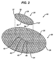
ここで図1〜3を参照すると、本発明の組織修復パッチ10が示されている。パッチ10は、メッシュ構成を有する。修復パッチ10は、実質的に平らな又は平面状の基部部材20及び閉鎖パッチ部材30を有するように見える。基部部材20は、実質的に楕円形状又は構成を有するように示されるが、正方形、矩形、円形、多角形など、これらの組み合わせなどを含む他の構成を有してもよい。基部部材20は、頂面22、底面24、及び周辺26を有するように見える。基部部材20を通して、対向側部44及び対向末端部43により画成された開口部42を有するスロット40が延びる。閉鎖パッチ部材30は、実質的に楕円構成を有する実質的に平らな又は平面状の部材であるように見える。閉鎖パッチ部材30は、頂面32、底面34、及び周辺35を有するように見える。閉鎖パッチ部材30は、対向湾曲末端部37及び対向側部38を有するように見える。パッチ部材30は、閉鎖パッチ30の底面34が基部部材20の頂面22に隣接するように、接続部39を介して末端部37に沿って基部部材20の頂部に装着されている。閉鎖パッチは、縫合、溶接、タッキング、リベット打ち、ステープル留め、接着などを含むが、これらに限定されない任意の従来の貼付方法を用いて装着されて、接続部39を形成する。閉鎖パッチ30は、基部部材20に装着されてスロット40及び開口部42を覆っている。側部38に隣接した開口部48は、スロット40の開口部42への及び開口部42を通した外科用器具のアクセス通路を提供する。図3に、パッチ10の基部部材20を組織にタックするのに使用できる、外科用タッキング器具60の部分概略図が見られる。器具60は、近位ハンドル62と、遠位端78を有する、遠位方向に延びる長尺状シャフト70とを有する。シャフト70の遠位部分76は、基部部材20の底面24の下方に配置されるように、開口部48、閉鎖フラップ30の底面34の下、及びスロット40の開口部42を通して延びているように見える。遠位端78は、外科用タックを発射して、基部部材20の頂面22及び閉鎖パッチ部材30の頂面32に隣接した組織にパッチを固定できるように、基部部材20の周辺26に近接して、底面24に隣接して位置付けられているように見える。修復パッチ10は、例えば、約1〜2cm毎に配置された定着地点を用いて、その周辺部26の周囲が組織に定着され、即ち定着装置又はタックは、約1cm〜2cmの距離、分離される。本発明の組織又はヘルニア修復パッチの多数の実施形態では、基部部材内にスロットを有して基部部材を通した開口部を提供することが好ましいが、開口部はスリット又は他のタイプの開口部であってもよく、円形、楕円形、矩形、多角形など、これらの組み合わせなどを含む異なる幾何学的構成を使用することができる。好ましくはないが、基部部材及び/又は閉鎖部材が湾曲し、又は、別様に1つを超える面内にあるように、本発明の組織修復パッチを形成することが可能である。
1-3, a tissue repair patch 10 of the present invention is shown. The patch 10 has a mesh configuration. Repair patch 10 appears to have a substantially flat or
タッキング又は他の従来の方法(例えば、ステープル留め、縫合など)により、本発明の組織修復パッチ10が一旦組織に移植及び固定されたら、外科用貼付器具60のシャフト部分76をスロット40を通して身体から除去する。閉鎖パッチ部材30は、下にある組織又は内臓がスロット40及び開口部42を通して移動することを防止する。
Once the tissue repair patch 10 of the present invention has been implanted and secured to tissue by tacking or other conventional methods (eg, stapling, suturing, etc.), the
図4に、組織修復パッチ10の代替的な実施形態を示す。パッチ10は類似した形状の基部部材20を有するように見えるが、閉鎖部材50は、短い対向末端側部56及び長い対向側部57を有する、実質的に矩形形状を有するように見える。閉鎖部材50は、頂面52と、基部部材20の頂面22に隣接した底面54とを有する。パッチ部材50は、短い側部56に沿って接続部59によってスロット40を覆って基部部材20に装着される。接続部は、前述したように作製されてもよい。側部57の真下の開口部48は、スロット40及び開口部42へのアクセスを提供する。図4に見られるように、組織修復パッチ10は、閉鎖部材50上又は閉鎖部材50内に含まれる方向指示物80を有するように見える。指示物50は、従来、部材50内又は部材50上に縫い付け、成形若しくは形成、印刷、染色、又は積層され得る。指示物80は、中央部分81を有するように見え、中央部分81は、該部分81から延びる対向横断部分82を有する。長手方向の部分85及び87が、対向する様式で長手方向に延びる。部分87は、部分85よりも太いように見える。指示物80により、外科医は、挿入後、組織修復パッチ10のそれぞれの軸線を患者及び切開部に関連して整合することにより、患者に関連したパッチの位置を決定することができ、貼付のためにタッキング器具を使用し又は外科用縫合糸を使用して、より正確な定着が可能となる。このような方向指示物は、本発明の組織修復パッチの別の実施形態と共に使用することができる。
FIG. 4 illustrates an alternative embodiment of the tissue repair patch 10. Although patch 10 appears to have a similarly shaped
ここで図5〜9を参照すると、本発明の組織修復パッチ100の代替的な実施形態が見られる。パッチ100は、実質的に平らな又は平面状の基部部分120及び140から形成された、実質的に平らな又は平面状の基部部材110を有するように見える。基部部材110は、底面112、頂面114及び周辺116を有する。基部部分120は、末端部124を有する直線状の側部122を有するように見える。基部部分120はまた、末端部124に接続する末端部128を有する湾曲側部126を有するように見える。蝶番状側部132及び自由末端部134を有する閉鎖フラップ部材130が、直線状側部122から外部へ延び、閉鎖フラップ部材130は、スロット136により側部122から分離されている。スロット136は、閉鎖末端部137及び開放末端部138を有する。閉鎖フラップ部材130は略矩形構成を有するように見えるが、円形、楕円形、多角形など、それらの組み合わせを含む他の幾何学的構成を有してもよい。基部部分140は、末端部144を有する直線状の側部142を有するように見える。基部部分140はまた、末端部144に接続する末端部148を有する湾曲側部146を有するように見える。蝶番状側部152及び自由末端部154を有する閉鎖フラップ部材150が、直線状側部142から外部へ延び、閉鎖フラップ部材150は、スロット156により側部142から分離されている。スロット156は、閉鎖末端部157及び開放末端部158を有する。閉鎖フラップ部材150は略矩形構成を有するように見えるが、円形、楕円形、多角形など、それらの組み合わせなどを含む他の幾何学的構成を有してもよい。基部部材110及び組織修復パッチ100は、基部部分を直線状側部122及び142に沿って、縫い目118に沿って接続することにより、基部部分120及び140から形成される。これは、縫合、溶接、タッキング、ステープル留め、接着など、及びこれらの組み合わせ、及びこれらの等価物を含む、任意の従来の方法で行うことができる。直線状側部122及び142のみが、閉鎖フラップ部材130及び150のいずれかの側部にて接続されることが理解され得る。閉鎖フラップ部材130及び150は、閉鎖フラップ130の蝶番状側部132がフラップ部材150のスロット156内に含まれ、閉鎖フラップ140の蝶番状側部152が閉鎖部材130のスロット136内に含まれるように、互いに装着される。このことは、貫通開口部165を有するスリット160を基部部材110内に形成し、スリット160は、基部部分120及び142のそれぞれの直線状側部122及び142の内側部分により画成され、またフラップ部材130及び150のそれぞれの蝶番状側部132及び152によっても画成される。図6に見られるような静止位置では、フラップ部材130は、基部部材110の基部部分140の頂面145上に静止すると共に、フラップ部材150は基部部分120の頂面125上に静止する。この静止構成では、スリット160及び開口部165は覆われている。組織修復パッチ100は、図8にて準備位置にあるように見え、閉鎖フラップ部材130及び150が直立位置にあり、定着器具が開口部165を通して挿入できるように、スリット160及び開口部を露出している。図9に、タッキング器具170が本発明の組織修復パッチ100と共に示されている。タッキング器具170は、近位ハンドル172及び作動引金174を有するように見える。遠位部分182及び遠位端184を有する湾曲シャフト180が、ハンドル170の遠位端176から延びる。遠位部分182は、上方向に延びるフラップ130及び150の間のスリット160及び開口部165を通して挿入されているように見え、それにより遠位端184は基部部材110の底面112の周囲を移動して、外科用タックを用いて基部部材を組織に固定することができる。タックがパッチ100の基部部分110を通して配置されてパッチ100を組織に固定した後、タッキング器具170はスリット160から除去されてもよく、2つのフラップ部材130及び150は、該フラップ部材を基部部材110の頂部114上へと下方向に折り畳み又は回転させることにより組み合わされてもよい。フラップ部材の一方又は両方は、場合により、接着剤、縫合糸、外科用締結具などを含む様々な従来の閉鎖方法を用いて、基部部材110に接着又は貼付されてもよい。
5-9, an alternative embodiment of the
図10及び11に、本発明の単一面組織修復パッチの代替的な実施形態400が見られる。修復パッチ400は、頂面412及び底面414を有する基部部材410を有する。パッチは、周辺416を有する。側部422により画成された開口部424を有するスリット420が、基部部材410内に位置する。スリット420は、末端部428を有する。スリット420の周囲に外科用縫合糸430が装着され、外科用縫合糸430は、末端部432及び434、並びに外科用針436を有し、外科用針436は、末端部432に装着され、場合により、図示していないが、末端部434に装着される。縫合糸430は、従来のマットレス縫合(連続)構成にて開口部424の周囲に装着されている。図11に見られるように、開口部424は、縫合糸末端部432及び434を引っ張り、側部422を接近させることにより閉鎖される。所望であれば、縫合針436を使用して、組織を縫合糸430と係合させてもよい。図28及び29を参照すると、縫合糸装着の変形が示されている。修復パッチ450は修復パッチ400と類似しているが、丸みを帯びた角部457により接続された長い対向側部454及び短い対向側部456を有する矩形形状の基部部材451を有する。基部部材451は、底面458及び頂面459、並びに外周452を有する。基部部材451は、側部462により画成された開口部464を有する、中央に位置するスリット460を有する。スリット46は、末端部468を有する。末端部472及び474を有する外科用縫合糸470が、スリット460の周囲に装着されている。縫合糸470は、「靴紐」型の構成にて装着されている。縫合糸470は、開口部464の周囲においてスリット460の対向側部462と係合することにより、スリット46に装着されているように見える。縫合糸470は、スリット460の一方の末端部468に沿って互いに隣接して位置する末端部472及び474を有するように見える。スリット460は、パッチ450の配置後、末端部472及び474を牽引して開口部464を閉鎖することにより固定される。縫合糸460は、場合により、末端部472及び474の一方又は両方に装着された外科用針を有してもよい。基部部材410及び451は、任意の好適な幾何学的構成を有してもよい。
In FIGS. 10 and 11, an
図12及び13に、本発明の組織修復パッチ200の好ましい実施形態が見られる。パッチ200は、頂部212、底部214及び周辺216を有する、実質的に平らな又は平面状の基部部材210を有するように見える。基部部材210は、楕円形状を有するように見えるが、矩形、円形、正方形、多角形、これらの組み合わせなどを含む他の幾何学的形状を有してもよい。基部部材210内にスロット220が位置し、スロット22は該スロットを通した開口部222を有する。スロット220は、対向側部224及び225並びに湾曲末端部226により画成されている。パッチ200は、上部閉鎖フラップ230及び下部閉鎖フラップ240を有するように見える。上部閉鎖フラップ230は実質的に矩形形状を有するように見えるが、円形、楕円形、矩形、多角形などを含む他の幾何学的構成を有してもよい。フラップ230は、頂面231及び底面232を有するように見える。フラップ230は、対向末端側部237により接続された対向側部235及び236も有する。フラップ230は、該フラップ230をその側部235を、例えば縫合、接着、ステープル留め、溶接、リベット打ちなどの従来の方法で接続して縫い目239を形成することにより、スロット220の側部224に隣接して基部部材210の頂面212に装着される。この方法で、フラップ230は、基部部材210の頂面212に面するその底面232を有し、静止位置においてスロット220及び開口部222を覆うように配置される。閉鎖フラップは、縫い目239を中心として上方向に回転されて、スロット220及び開口部222の覆いを取り外してもよい。他方の閉鎖フラップ240が、基部部材210の底面214に装着されている。フラップ240は、頂面241及び底面242を有するように見える。フラップ24は、対向末端側部247により接続された対向側部245及び246も有する。フラップ240は、該フラップ240をその側部245を、例えば縫合、接着、ステープル留め、溶接、リベット打ちなどの従来の方法で接続して縫い目249を形成することにより、スロット220の側部225に隣接して基部部材210の底面214に装着される。この方法で、フラップ240は、基部部材210の底面214に面するその頂面241を有し、静止位置においてスロット220及び開口部222を覆うように配置される。閉鎖フラップは、縫い目249を中心として下方向に回転されて、スロット220及び開口部222の覆いを取り外してもよい。フラップ240はまた、縫い目249を中心として、スロット220及び開口部222を通して上方向に回転されてもよい。
12 and 13, a preferred embodiment of the
ここで図14、14a、14b、及び15〜17を参照すると、本発明の好ましい組織修復パッチ250が見られる。パッチ250はパッチ200と類似しているが、2つの別個の基部部分部材から、異なる方法で構成されている。パッチ250は、実質的に平らな又は平面状の基部部分270及び280から形成された、実質的に平らな又は平面状の基部部材260を有するように見える。基部部材260は、底面264、頂面262及び周辺266を有する。基部部分270は、末端部274を有する直線状側部272を有するように見える。基部部分270はまた、末端部274に接続する湾曲末端部278を有する側部276を有するように見える。蝶番状側部292及び自由末端部294を有する閉鎖フラップ部材290が、直線状側部272から外部へ延びる。閉鎖フラップ部材290は略矩形構成を有するように見えるが、円形、楕円形、矩形、多角形などを含む他の幾何学的構成を有してもよい。基部部分280は、末端部284を有する直線状の側部282を有するように見える。基部部分280はまた、末端部284に接続する湾曲末端部288を有する側部286を有するように見える。蝶番状側部302及び自由末端部304を有する閉鎖フラップ部材300が、直線状側部282から外部へ延びる。閉鎖フラップ部材300は略矩形構成を有するように見えるが、円形、楕円形、矩形、多角形などを含む他の幾何学的構成を有してもよい。基部部材260及びヘルニア閉鎖パッチ250は、基部部分を直線状側部272及び282に沿って、縫い目268に沿って接続することにより、基部部分270及び280から形成される。これは、縫合、溶接、タッキング、ステープル留め、接着など、及びこれらの組み合わせ、及びこれらの等価物を含む、任意の従来の方法で行うことができる。直線状側部272及び282は、閉鎖フラップ部材290及び300のいずれかの側部に接続されることによって、開口部315を有するスリット310を部材290と300との間に形成することが理解され得る。スリット310は、閉鎖フラップ部材290及び300の蝶番状側部292及び302により画成され、対向末端部312を有する。パッチ250及び基部部材260を組み立てる際、スリット310内の開口部315を通して閉鎖フラップ290を挿入する。図12及び図16に見られるような静止位置では、フラップ部材300は、基部部材260の基部部分270の頂面上に静止すると共に、フラップ部材290は基部部分280の底面上に静止する。静止状態では、閉鎖フラップ290及び300はそれぞれ、スリット310及び開口部315を覆っている。いずれの閉鎖フラップもスリット310及び開口部315を通して回転され得るが、図示したパッチ250は、閉鎖フラップ部材290がスリットを通して回転し、基部部材260の底面264に隣接して静止していることが認識されるであろう。加えて、スリット310は、スロットなどを含む他の幾何学的構成及び形状を有してもよい。
Referring now to FIGS. 14, 14a, 14b, and 15-17, a preferred
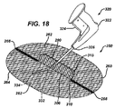
ここで図17〜22を参照すると、修復パッチ250は、ヘルニア修復手技などの組織修復手技において、組織に固定される準備位置にあるように見える。図17に見られるように、パッチは、フラップ300を基部部材260の頂部262から離れるように上方向へ回転させることにより、準備位置に配置されている。フラップ290も、スリット310及び開口部315を通して上方向に回転されているように見える。この方法で閉鎖フラップ290及び300を回転させることにより、スリット310及び開口部315は覆いが取り外されて、タッキング器具などの外科用器具、又は外科医の指にアクセスを提供する。図18に、本発明の組織修復パッチ250と共に外科用タッキング器具320が見られる。タッキング器具320は、近位ハンドル322及び作動引金324を有するように見える。遠位部分332及び遠位端334を有する湾曲シャフト330が、ハンドル322の遠位端326から延びる。遠位端部分332は上方向に延びるフラップ290及び300の間のスリット310及び開口部315を通して挿入されているように見え、それにより遠位端334は基部部材260の底面264の周囲を移動して、外科用タックを用いて基部部材260を組織に固定することができる。図20にて、ヘルニアパッチ250は患者内に移植されたように見える。外科的に形成された開口部372を有する身体壁370の断面が見られる。身体壁370は、内側腹膜層374、次の上部筋膜層375、次の筋肉層376、脂肪層377、及び最後に頂部皮膚層378を有するように見える。基部部材260の頂面262が腹膜層334に隣接して装着され、閉鎖フラップ部材290及び300が、開口部332の外へ及び該開口部332を通して延びているように見える。タッキング器具320のシャフト330は、外科開口部332を通し、スリット310及び開口部315を通して、患者の、下にある体腔内に挿入されているように見える。遠位端部分332及び遠位端334は、基部部材260の底面264に隣接して配置されて、基部部材260の部分を腹膜層374に取り付けているように見える。図19を参照すると、フラップ部材290及び300が場合により、末端部381及び382を有する外科用縫合糸380によって、それぞれそれらの底部側302及び292に沿って固定されているパッチ250が見られる。外科用針388は、縫合糸末端部281に取り付けられている。縫合されたフラップ部材は、スリット310内の開口部315を閉鎖する。代替的に、フラップ部材は、従来の接着剤、外科用締結具などによって互いに接合又は固定されてスリット310を閉鎖してもよい。フラップ部材290及び300は、代替的に、移植中、それらの静止位置で使用されてもよい。タッキング器具のシャフトは、フラップを上方向に回転させることなく、スリット310及び開口部315を通してフラップ300の下に挿入されるであろう。固定後、フラップは、更に固定されることなく、静止位置のまま残されてもよい。フラップ290は、組織又は内臓がスロット310及び開口部315内に移動することを防止し、フラップ290に対するいずれの圧力も、基部部材260の底面264に対してフラップ290を密封させ、スリット310を閉鎖するであろう。
Referring now to FIGS. 17-22, the
図21及び22に、本発明の組織修復パッチを固定するのに使用できる、直線状シャフト350を有する外科用タッキング器具340が見られる。器具340は、作動引金344を有する近位ハンドル342を有する。遠位部分352及び遠位端354を有する直線状シャフト350が、ハンドル340の遠位端346から延びる。遠位端部分352は、上方向に延びるフラップ290及び300の間のスリット310及び開口部315を通して挿入されているように見え、それにより遠位端354は基部部材260の底面264の周囲を移動して、外科用タックを用いて基部部材260を組織に固定することができる。図22にて、組織修復パッチ250は、患者内に移植されているように見える。外科的に形成された開口部372を有する身体壁370の断面が見られる。身体壁370は、内側腹膜層374、次の上部筋膜層375、次の筋肉層376、脂肪層377、及び最後に頂部皮膚層378を有するように見える。基部部材260の頂面262が腹膜層374に隣接して装着され、閉鎖フラップ部材290及び300が、開口部332の外へ及び該開口部332を通して延びているように見える。タッキング器具350のシャフト350は、外科開口部372を通し、スリット310及び開口部315を通して、患者の、下にある体腔内に挿入されているように見える。遠位端部分352及び遠位端354は、基部部材260の底面264に隣接して配置されて、基部部材260の部分を腹膜層374に取り付けているように見える。
FIGS. 21 and 22 show a surgical tacking
図23及び24は、ヘルニア欠損を修復するための、外科手技中の本発明の組織修復パッチ250の患者内への移植を示す。外科医は、一方の手で、引金324に係合すると共に外科用タッキング器具320のハンドル322を握っているように見える。器具は湾曲シャフト330を有し、シャフト330の近位部分332は、身体壁370の開口部372を通し、ヘルニア修復パッチ250のスリット315及び開口部350を通して配置されている。修復パッチ250は、基部部材260の上面262が腹膜層374に隣接するように、患者の体腔内に移植されている。閉鎖フラップ290及び300は、上方向に回転されてスリット310及び開口部315を露出しており、皮膚層378の上方に部分的に延びるように、身体壁370の開口部372を通して外部に延びている。患者の内臓379は、基部部材260の底面264に隣接しているように見える。タッキング器具320のシャフト330は、外科開口部372を通し、スリット310及び開口部315を通して、患者の、下にある体腔内に挿入されているように見える。遠位端部分332及び遠位端334は、基部部材260の底面264に隣接して配置されて、基部部材260の部分を腹膜層374に取り付けているように見える。外科医の他方の手は、遠位端334の上方において患者の身体壁370を触診して、引金324を作動させてタックを送達するのに先だって、該タックの位置を特定しているように見える。図26を参照すると、パッチ250を移植し、タック380で固定した後、基部部材260の底面264は、タック382及び384の2つの同心のクラウンを有して、パッチ250を腹膜層374に固定してもよい。
Figures 23 and 24 illustrate implantation of a
図25及び26に、本発明の組織修復パッチの別の実施形態が見られる。修復パッチ500は、頂面512及び底面514を有する実質的に平らな基部部材510を有するように見える。基部部材510は周辺522により画成された円形開口部520を有するように見える。閉鎖環530は、円形開口部520の周辺522の周囲に装着されているように見える。パッチ500は、頂面542及び底面544を有する閉鎖パッチ540も含む。パッチ540の底面544に、接合する閉鎖環548が装着されている。接合する閉鎖環548は、閉鎖環530と除去可能に係合されることができる。外科手技に使用する際、外科医は基部部材510から閉鎖パッチ540を除去することによって、開口部520を露出する。次いで、基部部材510の頂面512が腹膜などの体腔の内側層に隣接するように、基部部材510を患者の体腔内に移植する。次いで、外科医は、外科用タッカーなどの取り付け器具のシャフトの遠位部分を、開口部520を通して、基部部材510の底面514の下方の体腔内に挿入する基部部材510を組織の内側層に固定し、固定器具のシャフトを除去した後、外科医は、閉鎖パッチ540を、接合する閉鎖環548及び閉鎖環530が係合するように、基部部材510の頂面512に装着する。
25 and 26, another embodiment of the tissue repair patch of the present invention can be seen.
本発明の修復パッチは、場合により、十分に有効な量の治療薬などの活性薬剤を含み又は該活性薬剤で被覆されてもよい。活性薬剤として好適な物質は、天然由来のものであっても合成のものであってもよい従来の薬剤を含み、限定するものではないが、例えば、抗生物質、抗菌薬、抗細菌薬、防腐薬、化学療法薬、細胞分裂阻害薬、転移阻害薬、抗糖尿病薬(antideabetics)、抗真菌薬、婦人科薬剤、泌尿器科薬剤、抗アレルギー薬、性ホルモン、性ホルモン阻害薬、止血薬(haemostyptics)、ホルモン、ペプチドホルモン、抗うつ薬、ビタミンCなどのビタミン、抗ヒスタミン薬、ネイキッドDNA、プラスミドDNA、カチオンDNA複合体、RNA、細胞成分、ワクチン、身体内で自然発生する細胞又は遺伝子操作された細胞を含んでもよい。 The repair patches of the present invention may optionally include or be coated with an active agent, such as a sufficiently effective amount of a therapeutic agent. Substances suitable as active agents include, but are not limited to, conventional agents that may be naturally occurring or synthetic, such as antibiotics, antibacterial agents, antibacterial agents, antiseptics Drugs, chemotherapeutic drugs, cell division inhibitors, metastasis inhibitors, antidiabetics, antifungals, gynecological drugs, urological drugs, antiallergic drugs, sex hormones, sex hormone inhibitors, hemostatic drugs (haemostyptics) ), Hormones, peptide hormones, antidepressants, vitamins such as vitamin C, antihistamines, naked DNA, plasmid DNA, cationic DNA complexes, RNA, cellular components, vaccines, naturally occurring cells or genetically engineered in the body Cells may be included.
一実施形態において、活性薬剤は、ゲンタマイシン又はZEVTERA(商標)(セフトビプロールメドカリル)ブランドの抗生物質(Basilea Pharmaceutica Ltd.,Basel Switzerlandから入手可能)のような薬剤を含めた抗生物質であってもよい。一実施形態において、移植片は、オクテニジン、オクテニジン二塩酸塩(Schulke & Mayr,Norderstedt,GermanyからOctenisept(登録商標)殺菌薬の活性成分として入手可能)、ポリヘキサメチレンビグアニド(PHMB)(Braun,SwitzerlandによるLavasept(登録商標)の活性成分として入手可能)、トリクロサン、銅(Cu)、銀(Ag)、ナノ銀、金(Au)、セレニウム(Se)、ガリウム(Ga)、タウロリジン、N−クロロタウリン、リステリン(登録商標)口腔洗浄薬などのアルコール系消毒薬、N−ラウリル−L−アルギニンエチルエステル(LAE)、ミリスタミドプロピルジメチルアミン(MAPD)(SCHERCODINE(商標)Mの活性成分として入手可能)、オレアミドプロピルジメチルアミン(OAPD)(SCHERCODINE(商標)Oの活性成分として入手可能)、及び、ステアラミドプロピルジメチルアミン(SAPD)(SCHERCODINE(商標)Sの活性成分として入手可能)など、(体液の存在下でも)種々の細菌及び酵母菌に対して使用される広範な抗菌薬を含んでよい。一実施形態において、薬剤はオクテニジン二塩酸塩(以下、オクテニジンと呼ぶ)及び/又はPHMBであってもよい。 In one embodiment, the active agent is an antibiotic, including agents such as gentamicin or ZEVTERA ™ (ceftbiprole medicalyl) brand antibiotics (available from Basilea Pharmaceuticals Ltd., Basel Switzerland). Also good. In one embodiment, the graft is octenidine, octenidine dihydrochloride (available as an active ingredient of Octenisept® fungicide from Schulke & Mayr, Norderstedt, Germany), polyhexamethylene biguanide (PHMB) (Braun, Switzerland) Available as an active ingredient of Lavasept®), triclosan, copper (Cu), silver (Ag), nanosilver, gold (Au), selenium (Se), gallium (Ga), taurolidine, N-chlorotaurine , Alcoholic antiseptics such as Listerine® mouthwash, N-lauryl-L-arginine ethyl ester (LAE), myristamidopropyldimethylamine (MAPD) (SCHERCODENE ™ M activity Oleamidopropyldimethylamine (OAPD) (available as an active ingredient of SCHERCODEINE ™ O), and stearamidepropyldimethylamine (SAPD) (available as an active ingredient of SCHERCODEINE ™ S) A wide range of antibacterials used against various bacteria and yeasts (even in the presence of body fluids). In one embodiment, the agent may be octenidine dihydrochloride (hereinafter referred to as octenidine) and / or PHMB.
本発明のヘルニア修復パッチ装置内に、単一の、中央に位置する開口部を有することが好ましいが、開口部及び関連する閉鎖部材は、中央からずれていてもよい。加えて、1つを超える開口部及び閉鎖部材を本発明のヘルニア修復装置にて使用してもよい。 While it is preferred to have a single, centrally located opening in the hernia repair patch device of the present invention, the opening and associated closure member may be offset from the center. In addition, more than one opening and closure member may be used in the hernia repair device of the present invention.
下記の実施例は本発明の主旨及び実践の説明のためであり、これらに限定されるものではない。 The following examples are for the purpose of explaining the gist and practice of the present invention, but are not limited thereto.
(実施例1)
腹壁又は切開ヘルニアを有する患者を、以下の方法での開放ヘルニア修復手技のために準備する。ヘルニアを包囲する皮膚範囲を、ベタジンなどの従来の抗菌溶液で洗浄する。従来の方法で導入及び吸入によって、患者に従来の全身麻酔を投与する。次いで、外科医は、ヘルニアの上に存在する皮膚及び皮下組織内に切開部を作製することにより、外科手技を開始する。計画された腹膜内メッシュ配置の場合、ヘルニア嚢を開放する。欠損の周囲の健康な筋膜の縁を検査し、腹壁に対する内臓の任意の付着を分割して、メッシュ定着のための自由空間を形成する。
Example 1
A patient with an abdominal wall or incisional hernia is prepared for an open hernia repair procedure in the following manner. The area of skin surrounding the hernia is washed with a conventional antibacterial solution such as betadine. Conventional general anesthesia is administered to the patient by introduction and inhalation in a conventional manner. The surgeon then begins the surgical procedure by making an incision in the skin and subcutaneous tissue present over the hernia. For a planned intraperitoneal mesh arrangement, open the hernia sac. Examine the edges of the healthy fascia around the defect and split any attachment of the viscera to the abdominal wall to form a free space for mesh anchoring.
手技中のこの時点で、外科医は次いで、閉鎖フラップ及び基部部材を有する本発明のメッシュ組織修復ヘルニアパッチを、メッシュの頂面が、欠損を包囲する腹膜に隣接し、メッシュ装置の底面が患者の内臓の方向に面するように、腹壁欠損を通して腹腔内に挿入するよう準備する。所望により、滞在縫合糸(stay suture)をメッシュを通して腹部組織内に配置してもよく、即ちメッシュの4つの羅針盤の方位(北、南、東、西)に配置してもよい。配置後、フラップを上方向に回転させて、メッシュの基部部材内の開口部を露出する。従来の外科用タッカー又は他の定着手段を用いてメッシュを定着させる。タッカーの遠位端がメッシュと内臓との間にあるように、開口部を通してタッカーを挿入する。次いで、複数のタックを使用してメッシュの周辺部をクラウン構成にて定着させる。タッカーを除去し、フラップを本発明に適切なように折り畳むことにより、メッシュ内の開口部を閉鎖する。フラップは、場合により粘着剤、縫合糸、リベット、又は他の閉鎖手段を使用して固定されてもよく、又は、互いに固定されることなくそれらの静止位置に戻ってもよい。ヘルニア欠損は、所望であれば、最初に閉鎖されてもよい。適切な縫合又は閉鎖技術を用いて皮膚切開部を閉鎖し、切開部に適切に包帯をし、患者を回復室に移動する。 At this point in the procedure, the surgeon then applied the mesh tissue repair hernia patch of the present invention having a closure flap and base member to the top of the mesh adjacent to the peritoneum surrounding the defect and the bottom of the mesh device to the patient's bottom. Prepare to be inserted into the abdominal cavity through the abdominal wall defect so that it faces the viscera. If desired, stay sutures may be placed through the mesh into the abdominal tissue, i.e. in the four compass orientations (north, south, east, west) of the mesh. After placement, the flap is rotated upward to expose the opening in the mesh base member. The mesh is anchored using a conventional surgical tacker or other anchoring means. The tucker is inserted through the opening so that the distal end of the tucker is between the mesh and the viscera. Next, the periphery of the mesh is fixed in a crown configuration using a plurality of tacks. The opening in the mesh is closed by removing the tucker and folding the flaps as appropriate for the present invention. The flaps may optionally be secured using adhesives, sutures, rivets, or other closure means, or may return to their resting position without being secured together. The hernia defect may be closed first if desired. The skin incision is closed using appropriate suturing or closure techniques, the incision is properly dressed, and the patient is moved to the recovery room.
本発明の新規なヘルニア修復装置は、多くの利点を有する。新規な修復パッチ装置は、開放腹腔内ヘルニア修復手技においてタッキングを介して貼付できる単一層メッシュ修復装置を提供する。修復パッチ装置は、より少ない異物(即ち、より少ない異物塊)、及び開放手技において単一層組織修復メッシュを移植する能力を含む更なる利点を有する。本発明の組織修復装置は、好ましくはメッシュから作製され、組織一体化の速度を加速する可能性があり得、バイオフィルム形成の範囲を低減し、製造費用を低減し、包装、滅菌、及び改善されたエルゴノミクスと共に使用することがより容易である。 The novel hernia repair device of the present invention has many advantages. The novel repair patch device provides a single layer mesh repair device that can be applied via tacking in an open intraperitoneal hernia repair procedure. The repair patch device has further advantages including fewer foreign bodies (ie, fewer foreign bodies) and the ability to implant a single layer tissue repair mesh in an open procedure. The tissue repair device of the present invention is preferably made from mesh and may accelerate the rate of tissue integration, reducing the scope of biofilm formation, reducing manufacturing costs, packaging, sterilization, and improvement It is easier to use with ergonomics.
以上、本発明をその詳細な実施形態について図示及び説明したが、当業者であれば、特許請求される発明の趣旨及び範囲から逸脱することなく本発明の形態及び詳細に様々な変更を行いうる点は理解されるであろう。 Although the present invention has been illustrated and described with reference to specific embodiments, those skilled in the art can make various changes to the forms and details of the present invention without departing from the spirit and scope of the claimed invention. The point will be understood.
〔実施の態様〕
(1) 組織修復パッチであって、
頂面及び底面を有する実質的に平らな基部部材と、
前記基部部材内に位置する開口部と、
前記開口部に関連した閉鎖部材と、を含む、組織修復パッチ。
(2) 前記基部部材の少なくとも片面に高分子層を更に含む、実施態様1に記載の組織修復パッチ。
(3) 前記基部部材の少なくとも片面に癒着バリアを更に含む、実施態様1に記載の組織修復パッチ。
(4) 前記基部部材がメッシュを含む、実施態様1に記載のパッチ。
(5) 前記基部部材が織物を含む、実施態様1に記載のパッチ。
Embodiment
(1) A tissue repair patch,
A substantially flat base member having a top surface and a bottom surface;
An opening located within the base member;
A tissue repair patch comprising a closure member associated with the opening.
(2) The tissue repair patch according to
(3) The tissue repair patch according to
(4) The patch according to
(5) The patch according to
(6) 前記織物が織布である、実施態様5に記載のパッチ。
(7) 前記織物が不織布である、実施態様5に記載のパッチ。
(8) 前記基部部材が、発泡高分子フィルム(expanded polymeric film)を含む、実施態様1に記載のパッチ。
(9) 前記基部部材が、生体適合性の非分解性ポリマーを含む、実施態様1に記載のパッチ。
(10) 前記基部部材が、生体吸収性ポリマーを含む、実施態様1に記載のパッチ。
(6) The patch according to embodiment 5, wherein the woven fabric is a woven fabric.
(7) The patch according to embodiment 5, wherein the woven fabric is a nonwoven fabric.
(8) The patch according to
(9) The patch according to
(10) The patch according to
(11) 前記非分解性ポリマーが、ポリプロピレン、ポリエステル、ナイロン、及び超高分子量ポリエチレンからなる群から選択される、実施態様9に記載のパッチ。
(12) 前記生体吸収性ポリマーが、ポリラクチド類、ポリグリコリド類、ポリジオキサノン類、ポリカプロラクトン類、グリコリド類及び炭酸トリメチレンのコポリマー、並びにラクチド類及び炭酸トリメチレンのコポリマー、並びにそれらのコポリマー及びブレンドからなる群から選択される、実施態様10に記載のパッチ。
(13) 前記基部部材が、生体適合性の非分解性ポリマー及び生体吸収性ポリマーを含む、実施態様1に記載のパッチ。
(14) 前記開口部がスリットである、実施態様1に記載のパッチ。
(15) 前記開口部が円形である、実施態様1に記載のパッチ。
(11) The patch according to embodiment 9, wherein the non-degradable polymer is selected from the group consisting of polypropylene, polyester, nylon, and ultrahigh molecular weight polyethylene.
(12) The bioabsorbable polymer is composed of polylactides, polyglycolides, polydioxanones, polycaprolactones, copolymers of glycolide and trimethylene carbonate, and lactides and trimethylene carbonate copolymers, and copolymers and blends thereof. Embodiment 11. The patch according to embodiment 10, selected from
(13) The patch according to
(14) The patch according to
(15) The patch according to
(16) 前記開口部がスロット形状である、実施態様1に記載のパッチ。
(17) 前記閉鎖部材が、前記開口部の周囲に蝶番的に装着された対向閉鎖フラップ部材を含む、実施態様1に記載の組織修復パッチ。
(18) 前記閉鎖部材が、外周を有するパッチを含み、前記外周の一部分が、前記開口部の周囲において前記基部部材の前記頂面に装着されている、実施態様1に記載の組織修復パッチ。
(19) 前記閉鎖部材が、前記開口部の周囲に装着された外科用縫合糸を含む、実施態様1に記載の組織修復パッチ。
(20) 前記閉鎖部材が、頂面及び底面を有し、かつ前記底面から係合部材が延びるパッチを含み、前記基部部材が、前記閉鎖パッチが前記基部部材に係合しかつ前記基部部材から係合解除できるように、前記開口部の周囲において前記頂面に装着された、接合する係合部材を有する、実施態様1に記載の組織修復パッチ。
(16) The patch according to
17. The tissue repair patch of
(18) The tissue repair patch according to
(19) The tissue repair patch according to
(20) The closure member includes a patch having a top surface and a bottom surface, and an engagement member extending from the bottom surface, the base member engaging the base member and the base member from the base member. The tissue repair patch according to
(21) 前記開口部が、対向側部を有するスリットを含み、前記閉鎖部材が、前記側部に隣接して前記スリットの周囲に通された外科用縫合糸を含む、実施態様1に記載の組織修復パッチ。
(22) 前記フラップが、スロットによって前記基部部材から分離された自由末端部部分を有し、それにより各閉鎖フラップ部材が、対向するフラップ部材の前記スロット内に係合され得る、実施態様17に記載の組織修復パッチ。
(23) 前記開口部が中央に位置する、実施態様1に記載のパッチ。
(24) 少なくとも2つの開口部及び閉鎖部材を含む、実施態様1に記載のパッチ。
(25) 前記ポリマーフィルムが非吸収性ポリマーを含む、実施態様2に記載のパッチ。
21. The embodiment of
(22) In embodiment 17, wherein the flap has a free end portion separated from the base member by a slot so that each closure flap member can be engaged in the slot of the opposing flap member. The tissue repair patch described.
(23) The patch according to
24. A patch according to
(25) A patch according to embodiment 2, wherein the polymer film comprises a non-absorbable polymer.
(26) 前記ポリマーフィルムが生体吸収性ポリマーを含む、実施態様2に記載のパッチ。
(27) 前記ポリマーが、シリコーン、PTFE、ポリエステル、及びポリプロピレンからなる群から選択される、実施態様25に記載のパッチ。
(28) 前記生体吸収性ポリマーが、酸化再生セルロース、ポリジオキサノン、ポリグレカプロン25(グリコリド及びε−カプロラクトンのコポリマー)及びこれらの組み合わせからなる群から選択される、実施態様26に記載のパッチ。
(29) 前記ポリマーフィルムが癒着バリアである、実施態様2に記載のパッチ。
(30) 前記癒着バリアが、酸化再生セルロース、ポリジオキサノン、ポリグレカプロン25(グリコリド及びε−カプロラクトンのコポリマー)及びこれらの組み合わせからなる群からなる群から選択されるポリマーを含む、実施態様3に記載のパッチ。
(26) The patch of embodiment 2, wherein the polymer film comprises a bioabsorbable polymer.
27. The patch according to embodiment 25, wherein the polymer is selected from the group consisting of silicone, PTFE, polyester, and polypropylene.
(28) The patch according to
(29) The patch according to embodiment 2, wherein the polymer film is an adhesion barrier.
(30) The embodiment 3, wherein the adhesion barrier comprises a polymer selected from the group consisting of oxidized regenerated cellulose, polydioxanone, polygrecaprone 25 (a copolymer of glycolide and ε-caprolactone) and combinations thereof. Patch.
(31) 前記癒着バリアが、シリコーン、PTFE、及びePTFEからなる群から選択されるポリマーを含む、実施態様3に記載のパッチ。
(32) 身体壁欠損修復を行う方法であって、
A.組織欠損を有する身体壁の内側層上に組織修復パッチを挿入する工程であって、前記修復パッチが、
頂面及び底面を有する実質的に平らな基部部材と、
前記基部部材内に位置する開口部と、
前記開口部に関連した閉鎖部材と、を含む、工程と、
B.前記基部部材の前記頂面が、前記身体壁の前記内側層に隣接するように、前記パッチを前記欠損の周囲に配置する工程と、
C.外科用定着器具の末端部を、前記開口部を通して挿入して、前記基部部材の前記底面にアクセスし、前記基部部材を前記身体壁の前記内側層に定着させる工程と、
D.前記閉鎖部材を操作して、前記開口部を閉鎖する工程と、を含む、方法。
(33) 前記組織修復パッチが、前記基部部材の少なくとも片面に高分子層を更に含む、実施態様32に記載の方法。
(34) 前記組織欠損がヘルニアである、実施態様33に記載の方法。
31. The patch of embodiment 3, wherein the adhesion barrier comprises a polymer selected from the group consisting of silicone, PTFE, and ePTFE.
(32) A method of repairing a body wall defect,
A. Inserting a tissue repair patch on an inner layer of a body wall having a tissue defect, the repair patch comprising:
A substantially flat base member having a top surface and a bottom surface;
An opening located within the base member;
A closure member associated with the opening, and
B. Disposing the patch around the defect such that the top surface of the base member is adjacent to the inner layer of the body wall;
C. Inserting a distal end of a surgical anchoring instrument through the opening to access the bottom surface of the base member and anchoring the base member to the inner layer of the body wall;
D. Manipulating the closure member to close the opening.
33. The method of
(34) A method according to embodiment 33, wherein the tissue defect is hernia.
Claims (20)
頂面及び底面を有する実質的に平らな基部部材と、
前記基部部材内に位置する開口部と、
前記開口部に関連した閉鎖部材と、を含み、
前記実質的に平らな基部部材が、第1の頂面、第1の底面、第1の直線状側部、及び、前記第1の直線状側部に結合している第1の連結部および前記第1の直線状側部から切り離されている第1のスリット部を有する第1の閉鎖フラップ部材を有する第1の基部部分、及び、第2の頂面、第2の底面、第2の直線状側部、及び、前記第2の直線状側部に結合している第2の連結部および前記第2の直線状側部から切り離されている第2のスリット部を有する第2の閉鎖フラップ部材を有する第2の基部部分を含み、
前記第1の基部部分および前記第2の基部部分が組み合わされて、前記第1の基部部分の前記第1の閉鎖フラップ部材が、前記第2の基部部分の前記第2の頂面上に置かれており、前記第2の基部部分の前記第2の閉鎖フラップ部材が、前記第1の基部部分の前記第1の頂面上に置かれている第1の状態において、前記第1の基部部分の前記第1の閉鎖フラップ部材の前記第1の連結部および前記第2の基部部分の前記第2の閉鎖フラップ部材の前記第2の連結部が、前記閉鎖部材を構成して、前記第1の基部部分の前記第1の閉鎖フラップ部材の前記第1のスリット部および前記第2の基部部分の前記第2の閉鎖フラップ部材の前記第2のスリット部により形成される前記開口部が塞がれて、外科用器具を前記開口部に挿入することができず、前記第1の基部部分の前記第1の閉鎖フラップ部材が、前記第2の基部部分の前記第2の頂面に対して直立位置にあり、前記第2の基部部分の前記第2の閉鎖フラップ部材が、前記第1の基部部分の前記第1の頂面に対して直立位置にある第2の状態において、前記外科用器具を、前記第1の基部部分の前記第1の閉鎖フラップ部材の前記第1のスリット部および前記第2の基部部分の前記第2の閉鎖フラップ部材の前記第2のスリット部により形成される前記開口部を通して挿入することができる、組織修復パッチ。 A tissue repair patch,
A substantially flat base member having a top surface and a bottom surface;
An opening located within the base member;
A closure member associated with the opening, only including,
The substantially flat base member includes a first top surface, a first bottom surface, a first straight side portion, and a first coupling portion coupled to the first straight side portion; A first base portion having a first closure flap member having a first slit portion separated from the first linear side portion; and a second top surface, a second bottom surface, a second A second closure having a straight side, a second connecting portion coupled to the second straight side, and a second slit separated from the second straight side; Including a second base portion having a flap member;
The first base portion and the second base portion are combined to place the first closure flap member of the first base portion on the second top surface of the second base portion. The first base portion in a first state wherein the second closure flap member of the second base portion is positioned on the first top surface of the first base portion. The first connecting portion of the first closing flap member of the portion and the second connecting portion of the second closing flap member of the second base portion constitute the closing member; The opening formed by the first slit portion of the first closing flap member of the first base portion and the second slit portion of the second closing flap member of the second base portion is closed. So that surgical instruments can be inserted into the openings. The first closure flap member of the first base portion is in an upright position relative to the second top surface of the second base portion and the second closure of the second base portion In a second state, wherein the flap member is in an upright position with respect to the first top surface of the first base portion, the surgical instrument is moved to the first closure flap member of the first base portion. A tissue repair patch that can be inserted through the opening formed by the second slit portion of the second closure flap member of the second base portion of the first slit portion .
Applications Claiming Priority (3)
| Application Number | Priority Date | Filing Date | Title |
|---|---|---|---|
| US13/443,347 | 2012-04-10 | ||
| US13/443,347 US9820837B2 (en) | 2012-04-10 | 2012-04-10 | Single plane tissue repair patch |
| PCT/US2013/035961 WO2013155174A1 (en) | 2012-04-10 | 2013-04-10 | Single plane tissue repair patch |
Publications (2)
| Publication Number | Publication Date |
|---|---|
| JP2015519099A JP2015519099A (en) | 2015-07-09 |
| JP6211587B2 true JP6211587B2 (en) | 2017-10-11 |
Family
ID=48190610
Family Applications (1)
| Application Number | Title | Priority Date | Filing Date |
|---|---|---|---|
| JP2015505872A Expired - Fee Related JP6211587B2 (en) | 2012-04-10 | 2013-04-10 | Single-sided tissue repair patch |
Country Status (10)
| Country | Link |
|---|---|
| US (2) | US9820837B2 (en) |
| EP (1) | EP2836158A1 (en) |
| JP (1) | JP6211587B2 (en) |
| CN (1) | CN104220024B (en) |
| AU (1) | AU2013246011B2 (en) |
| CA (1) | CA2869931A1 (en) |
| IN (1) | IN2014DN07771A (en) |
| RU (1) | RU2628622C2 (en) |
| WO (1) | WO2013155174A1 (en) |
| ZA (1) | ZA201408164B (en) |
Families Citing this family (29)
| Publication number | Priority date | Publication date | Assignee | Title |
|---|---|---|---|---|
| USD342022S (en) * | 1991-05-28 | 1993-12-07 | Beecham, Inc. | Combined compartmented bottle and closure |
| US9820837B2 (en) * | 2012-04-10 | 2017-11-21 | Ethicon, Inc. | Single plane tissue repair patch |
| US9364228B2 (en) | 2012-05-11 | 2016-06-14 | Ethicon, Llc | Applicator instruments having distal end caps for facilitating the accurate placement of surgical fasteners during open repair procedures |
| US8518055B1 (en) | 2012-05-11 | 2013-08-27 | Ethicon, Inc. | Applicator instruments for dispensing surgical fasteners during open repair procedures |
| US10575716B2 (en) | 2012-05-11 | 2020-03-03 | Ethicon Llc | Applicator instruments with imaging systems for dispensing surgical fasteners during open repair procedures |
| US10245135B2 (en) | 2013-07-08 | 2019-04-02 | Bg Medical, Llc | Segmented skirted surgical mesh |
| USD772410S1 (en) * | 2013-08-05 | 2016-11-22 | Bg Medical, Llc | Hernia mesh |
| USD734458S1 (en) * | 2013-08-05 | 2015-07-14 | Bg Medical, Llc | Hernia mesh |
| CA2940476C (en) | 2014-03-06 | 2019-05-07 | C.R. Bard, Inc. | Hernia repair patch |
| RU2699811C1 (en) | 2014-03-07 | 2019-09-11 | Айконлаб Инк. | Multipurpose implant with specified surface structure for soft tissue reconstruction |
| US10588732B2 (en) | 2014-03-07 | 2020-03-17 | IconLab USA, Inc. | Multipurpose implant with modeled surface structure for soft tissue reconstruction |
| USD770047S1 (en) * | 2014-08-27 | 2016-10-25 | Johnson & Johnson Medical Gmbh | Surgical mesh implant having a floating thread grid marker |
| USD770046S1 (en) * | 2014-09-08 | 2016-10-25 | Johnson & Johnson Medical Gmbh | Surgical mesh implant |
| US10172700B2 (en) | 2014-12-01 | 2019-01-08 | C.R. Bard, Inc. | Prosthesis for repairing a hernia defect |
| EP3273906A4 (en) | 2015-03-24 | 2018-11-07 | Hexagon Health, Inc. | Gender-specific mesh implant with barrier for inguinal hernia repair |
| US9713520B2 (en) * | 2015-06-29 | 2017-07-25 | Ethicon, Inc. | Skirted tissue repair implant having position indication feature |
| CN108430386B (en) * | 2015-10-08 | 2020-10-30 | 阿特利姆医疗公司 | Medical device with detachable configuration device and fixing element |
| WO2017074639A1 (en) * | 2015-10-30 | 2017-05-04 | Ethicon Llc | Surgical implant |
| DE102015013989A1 (en) * | 2015-10-30 | 2017-05-04 | Johnson & Johnson Medical Gmbh | Surgical implant |
| WO2017074671A1 (en) * | 2015-10-30 | 2017-05-04 | Ethicon Llc | Surgical implant and process of manufacturing thereof |
| DE102015013992A1 (en) | 2015-10-30 | 2017-05-04 | Johnson & Johnson Medical Gmbh | Surgical implant and method for its production |
| AU2016381284B2 (en) | 2015-12-28 | 2021-04-29 | C.R. Bard, Inc. | Prosthesis for repairing a hernia defect |
| EP3223181B1 (en) * | 2016-03-24 | 2019-12-18 | Sofradim Production | System and method of generating a model and simulating an effect on a surgical repair site |
| US10245817B2 (en) | 2016-09-16 | 2019-04-02 | Ethicon, Inc. | Method of laminating absorbable semi-crystalline polymeric films |
| AU201817459S (en) * | 2018-06-12 | 2019-01-17 | HATCH Collection LLC | Abdominal sheet mask |
| US11376382B2 (en) | 2018-12-18 | 2022-07-05 | Daniel W. Borvan | Oral mandibular airway device and method |
| US11896472B2 (en) | 2019-10-28 | 2024-02-13 | Grant Technologies Llc | Surgical mesh having ingrowth-preventing coating on one side thereof, and method for making the same |
| CN113827769A (en) * | 2021-10-09 | 2021-12-24 | 段降龙 | Degradable medical biological patch material and preparation method and application thereof |
| US12004937B1 (en) | 2023-01-13 | 2024-06-11 | Sheridan Technologies Llc | Blunt dissector, delivery and deployment device for delivery and deployment of surgical mesh during soft tissue repairs |
Family Cites Families (130)
| Publication number | Priority date | Publication date | Assignee | Title |
|---|---|---|---|---|
| US4693720A (en) * | 1985-09-23 | 1987-09-15 | Katecho, Incorporated | Device for surgically repairing soft tissues and method for making the same |
| WO1992013500A1 (en) * | 1991-02-08 | 1992-08-20 | Surgical Innovations, Inc. | Method and apparatus for repair of inguinal hernias |
| US5258000A (en) | 1991-11-25 | 1993-11-02 | Cook Incorporated | Tissue aperture repair device |
| US5176692A (en) | 1991-12-09 | 1993-01-05 | Wilk Peter J | Method and surgical instrument for repairing hernia |
| WO1993017635A1 (en) | 1992-03-04 | 1993-09-16 | C.R. Bard, Inc. | Composite prosthesis and method for limiting the incidence of postoperative adhesions |
| US6312442B1 (en) * | 1992-06-02 | 2001-11-06 | General Surgical Innovations, Inc. | Method for developing an anatomic space for laparoscopic hernia repair |
| US5743917A (en) | 1993-01-13 | 1998-04-28 | Saxon; Allen | Prosthesis for the repair of soft tissue defects |
| CA2114282A1 (en) | 1993-01-28 | 1994-07-29 | Lothar Schilder | Multi-layered implant |
| US6113623A (en) | 1994-04-20 | 2000-09-05 | Cabinet Beau De Lomenie | Prosthetic device and method for eventration repair |
| US5425740A (en) * | 1994-05-17 | 1995-06-20 | Hutchinson, Jr.; William B. | Endoscopic hernia repair clip and method |
| DE4447557C2 (en) * | 1994-08-18 | 1997-10-23 | Harren Ernst Diethelm | Puncture closure |
| US5769864A (en) | 1994-09-29 | 1998-06-23 | Surgical Sense, Inc. | Hernia mesh patch |
| US6290708B1 (en) | 1994-09-29 | 2001-09-18 | Bard Asdi Inc. | Hernia mesh patch with seal stiffener |
| US5916225A (en) * | 1994-09-29 | 1999-06-29 | Surgical Sense, Inc. | Hernia mesh patch |
| US6176863B1 (en) * | 1994-09-29 | 2001-01-23 | Bard Asdi Inc. | Hernia mesh patch with I-shaped filament |
| US6174320B1 (en) * | 1994-09-29 | 2001-01-16 | Bard Asdi Inc. | Hernia mesh patch with slit |
| US6171318B1 (en) | 1994-09-29 | 2001-01-09 | Bard Asdi Inc. | Hernia mesh patch with stiffening layer |
| US5634931A (en) | 1994-09-29 | 1997-06-03 | Surgical Sense, Inc. | Hernia mesh patches and methods of their use |
| US6280453B1 (en) * | 1994-09-29 | 2001-08-28 | Bard Asdi Inc. | Hernia mesh patch with stiffener line segment |
| FR2728776B1 (en) * | 1994-12-30 | 1997-07-18 | Cogent Sarl | PROSTHETIC ELEMENT FOR THE TREATMENT OF HERNIA OF THE GROWTH, PARTICULARLY BY COELIOSCOPIC |
| WO1997035533A1 (en) | 1996-03-25 | 1997-10-02 | Enrico Nicolo | Surgical mesh prosthetic material and methods of use |
| US5716409A (en) | 1996-10-16 | 1998-02-10 | Debbas; Elie | Reinforcement sheet for use in surgical repair |
| FR2754705B1 (en) | 1996-10-18 | 1998-12-18 | Cogent Sarl | ANATOMICAL PROSTHESIS FOR THE REPAIR OF HERNIA BY LAPAROSCOPIC OR OPEN ROUTE |
| US5861003A (en) | 1996-10-23 | 1999-01-19 | The Cleveland Clinic Foundation | Apparatus and method for occluding a defect or aperture within body surface |
| DE69808614T2 (en) * | 1997-02-13 | 2003-06-18 | Boston Scientific Ltd., St. Michael | STABILIZATION SLING FOR USE IN MINIMALLY INVASIVE PELVIC SURGERY |
| US5922026A (en) * | 1997-05-01 | 1999-07-13 | Origin Medsystems, Inc. | Surgical method and prosthetic strip therefor |
| US6120539A (en) | 1997-05-01 | 2000-09-19 | C. R. Bard Inc. | Prosthetic repair fabric |
| US6066776A (en) | 1997-07-16 | 2000-05-23 | Atrium Medical Corporation | Self-forming prosthesis for repair of soft tissue defects |
| US6241768B1 (en) | 1997-08-27 | 2001-06-05 | Ethicon, Inc. | Prosthetic device for the repair of a hernia |
| FR2769825B1 (en) | 1997-10-22 | 1999-12-03 | Cogent Sarl | PROSTHETIC IMPLANT, ANATOMIC CHANNEL SHUTTER, AND SHUTTER ASSEMBLY COMPRISING SAME |
| US6319264B1 (en) | 1998-04-03 | 2001-11-20 | Bionx Implants Oy | Hernia mesh |
| DE19832634A1 (en) | 1998-07-09 | 2000-01-13 | Ethicon Endo Surgery Europe | Multilayer flat implant especially for hernia treatment |
| US6669735B1 (en) | 1998-07-31 | 2003-12-30 | Davol, Inc. | Prosthesis for surgical treatment of hernia |
| US6723133B1 (en) | 1998-09-11 | 2004-04-20 | C. R. Bard, Inc. | Performed curved prosthesis having a reduced incidence of developing wrinkles or folds |
| IT246470Y1 (en) | 1999-01-19 | 2002-04-09 | Beretta Luciano | MODEL OF BIOCOMPATIBLE PROSTHESIS SUITABLE FOR THE SURGICAL CORRECTION OF INGUINAL HERNIAS |
| US20030040809A1 (en) | 1999-03-20 | 2003-02-27 | Helmut Goldmann | Flat implant for use in surgery |
| US6258124B1 (en) | 1999-05-10 | 2001-07-10 | C. R. Bard, Inc. | Prosthetic repair fabric |
| US6383201B1 (en) | 1999-05-14 | 2002-05-07 | Tennison S. Dong | Surgical prosthesis for repairing a hernia |
| DE60045877D1 (en) * | 1999-06-09 | 2011-06-01 | Ethicon Inc | DEVICE FOR ADJUSTING POLYMER IMPLANTS ON SOFT SURFACES |
| JP4233254B2 (en) | 1999-07-28 | 2009-03-04 | シー・アール・バード・インコーポレーテッド | Hernia prosthesis |
| FR2807936B1 (en) * | 2000-04-20 | 2002-08-02 | Sofradim Production | ABDOMINAL WALL REINFORCEMENT FOR THE TREATMENT OF INGUINAL HERNIA BY ANTERIOR VOLTAGE-FREE |
| FR2807937B1 (en) * | 2000-04-20 | 2002-08-02 | Sofradim Production | GRIPPED PROSTHETIC KNIT, MANUFACTURING METHOD THEREOF AND REINFORCEMENT IMPLANT FOR THE TREATMENT OF WALL DEFICITS |
| US6610006B1 (en) | 2000-07-25 | 2003-08-26 | C. R. Bard, Inc. | Implantable prosthesis |
| US6746458B1 (en) | 2000-09-07 | 2004-06-08 | William G. Cloud | Mesh material to repair hernias |
| US7404819B1 (en) | 2000-09-14 | 2008-07-29 | C.R. Bard, Inc. | Implantable prosthesis |
| US6551356B2 (en) | 2001-03-19 | 2003-04-22 | Ethicon, Inc. | Pocketed hernia repair |
| US20030004581A1 (en) | 2001-06-27 | 2003-01-02 | Rousseau Robert A. | Implantable prosthetic mesh system |
| FR2829922B1 (en) * | 2001-09-21 | 2004-06-18 | Sofradim Production | COMPLETE AND UNIVERSAL IMPLANT FOR THE REPAIR OF HERNIA BY ANTERIOR |
| US6800082B2 (en) | 2001-10-19 | 2004-10-05 | Ethicon, Inc. | Absorbable mesh device |
| JP2003173843A (en) | 2001-12-06 | 2003-06-20 | Jst Mfg Co Ltd | Electric connector with wire holding mechanism |
| US6790213B2 (en) | 2002-01-07 | 2004-09-14 | C.R. Bard, Inc. | Implantable prosthesis |
| US6736854B2 (en) | 2002-05-10 | 2004-05-18 | C. R. Bard, Inc. | Prosthetic repair fabric with erosion resistant edge |
| US7011688B2 (en) | 2002-05-10 | 2006-03-14 | C.R. Bard, Inc. | Prosthetic repair fabric |
| US6736823B2 (en) * | 2002-05-10 | 2004-05-18 | C.R. Bard, Inc. | Prosthetic repair fabric |
| US7101381B2 (en) | 2002-08-02 | 2006-09-05 | C.R. Bard, Inc. | Implantable prosthesis |
| CN2590576Y (en) | 2002-12-30 | 2003-12-10 | 周建平 | Netted mantle sheet for repairing abdominal external hernia |
| WO2004071349A2 (en) | 2003-02-11 | 2004-08-26 | C.R. Bard, Inc. | Implantable hernia repair system |
| ES2220213B1 (en) | 2003-05-20 | 2006-01-16 | Juan Manuel Bellon Caneiro | DOUBLE MESH COMPOSITE PROTESIS THAT CORRECTES ABDOMINAL WALL DEFECTS, AND PREVENTS THE FORMATION OF ADHERENCES IN THE PERITONEAL INTERFACE. |
| US20050192600A1 (en) | 2004-02-24 | 2005-09-01 | Enrico Nicolo | Inguinal hernia repair prosthetic |
| DE102004009894A1 (en) | 2004-02-26 | 2005-09-15 | Gfe Medizintechnik Gmbh | Hernia mesh for the treatment of inguinal and hiatal hernias |
| JP4977600B2 (en) | 2004-04-20 | 2012-07-18 | ジェンザイム・コーポレーション | Surgical mesh implant |
| DE102004020469A1 (en) | 2004-04-26 | 2005-11-10 | Gfe Medizintechnik Gmbh | Flat mesh implant for hernia repair |
| US20050288775A1 (en) | 2004-06-24 | 2005-12-29 | Scimed Life Systems, Inc. | Metallic fibers reinforced textile prosthesis |
| US20050288691A1 (en) | 2004-06-28 | 2005-12-29 | Leiboff Arnold R | Hernia patch |
| US8795383B2 (en) | 2004-07-19 | 2014-08-05 | Alfredo Alvarado | Laparoscopic inguinal hernia prosthesis |
| CN100558317C (en) | 2004-07-20 | 2009-11-11 | 依威克萨医药公司 | The prosthesis of umbilical hernia or paromphalocele |
| CN101018512B (en) * | 2004-08-13 | 2011-05-18 | 马斯特生物外科股份公司 | Surgical prosthesis having biodegradable and nonbiodegradable regions |
| US8298290B2 (en) | 2004-09-20 | 2012-10-30 | Davol, Inc. | Implantable prosthesis for soft tissue repair |
| IL164591A0 (en) | 2004-10-14 | 2005-12-18 | Hernia repair device | |
| DE102004062798A1 (en) | 2004-12-20 | 2006-06-29 | Aesculap Ag & Co. Kg | Flat implant and method for its production |
| US7789888B2 (en) | 2005-02-14 | 2010-09-07 | Bartee Chad M | PTFE composite multi-layer material |
| US20060253203A1 (en) | 2005-05-03 | 2006-11-09 | Alfredo Alvarado | Hernial prosthesis for intraprosthetic fixation |
| US20060265005A1 (en) * | 2005-05-20 | 2006-11-23 | Beese Stephen A | Kit and a method for closing a wound |
| AU2006304552B2 (en) | 2005-10-18 | 2012-01-19 | Cook Biotech Incorporated | Medical device with affixation means |
| CA2636363A1 (en) | 2006-01-12 | 2007-08-02 | Minnesota Medical Development, Inc. | Hernia patch frame |
| WO2007115110A2 (en) | 2006-03-29 | 2007-10-11 | The Catheter Exchange, Inc. | Method and device for cavity obliteration |
| FR2901467B1 (en) | 2006-05-24 | 2008-08-15 | Aspide Medical Soc Par Actions | ANATOMIC PROSTHESIS FOR THE TREATMENT OF HERNIA, SUCH AS INGUINAL AND CRURAL HERNIA AND OTHER |
| US20070299538A1 (en) | 2006-06-26 | 2007-12-27 | Roeber Peter J | Ease of use tissue repair patch |
| GB0617037D0 (en) | 2006-08-30 | 2006-10-11 | Karbon Kinetics Ltd | Bicycle shock absorber with combined bearing shaft |
| US7828854B2 (en) * | 2006-10-31 | 2010-11-09 | Ethicon, Inc. | Implantable repair device |
| US9492596B2 (en) | 2006-11-06 | 2016-11-15 | Atrium Medical Corporation | Barrier layer with underlying medical device and one or more reinforcing support structures |
| US20080147099A1 (en) | 2006-12-14 | 2008-06-19 | Yih-Huei Uen | Bilayer patch device for hernia repair |
| US8652154B2 (en) * | 2006-12-28 | 2014-02-18 | Orthovita, Inc. | Non-resorbable implantable guides |
| US20110184441A1 (en) | 2007-01-10 | 2011-07-28 | Pascal St-Germain | Prosthetic repair patch with integrated sutures and method therefor |
| WO2008086469A1 (en) | 2007-01-10 | 2008-07-17 | Cook Biotech Incorporated | Implantable devices useful for reinforcing a surgically created stoma |
| DE102007008538A1 (en) | 2007-02-21 | 2008-08-28 | Universitätsklinikum Freiburg | Implant for the treatment of hernias |
| US20090192530A1 (en) | 2008-01-29 | 2009-07-30 | Insightra Medical, Inc. | Fortified mesh for tissue repair |
| US20080255593A1 (en) | 2007-04-12 | 2008-10-16 | Pascal St-Germain | Prosthetic repair patch with suture retaining structure |
| US8343231B1 (en) * | 2007-04-17 | 2013-01-01 | Christoudias George C | Surgical mesh for hernia repair |
| WO2009003726A1 (en) | 2007-07-02 | 2009-01-08 | Loehde Eckhard | Three-dimensional hernia mesh |
| FR2920671B1 (en) | 2007-09-07 | 2010-08-13 | Cousin Biotech | TEXTILE IMPLANT, IN PARTICULAR FOR THE REFECTION OF HERNIES |
| US7875074B2 (en) * | 2007-09-19 | 2011-01-25 | Ethicon, Inc. | Naturally contoured, preformed, three dimensional mesh device for breast implant support |
| US8500759B2 (en) * | 2007-09-26 | 2013-08-06 | Ethicon, Inc. | Hernia mesh support device |
| JPWO2009050890A1 (en) | 2007-10-16 | 2011-02-24 | 孝吏 堀 | Sore Hernia Treatment Patch |
| US20090099579A1 (en) | 2007-10-16 | 2009-04-16 | Tyco Healthcare Group Lp | Self-adherent implants and methods of preparation |
| EP3225209B1 (en) | 2007-10-17 | 2023-05-24 | Davol, Inc. | Fixating means between a mesh and mesh deployment means especially useful for hernia repair surgeries |
| US20100298953A1 (en) | 2007-10-31 | 2010-11-25 | Vanderbilt University | Device and method for positioning a surgical prosthesis |
| US9308068B2 (en) | 2007-12-03 | 2016-04-12 | Sofradim Production | Implant for parastomal hernia |
| EP3178442A1 (en) * | 2007-12-07 | 2017-06-14 | C.R. Bard Inc. | Implantable prosthesis |
| DE102007062273A1 (en) | 2007-12-14 | 2009-06-18 | Aesculap Ag | Fluorinated implant |
| DE102007063214B4 (en) | 2007-12-20 | 2019-06-27 | Aesculap Ag | Flat implant, especially for hernia care |
| FR2929835B1 (en) | 2008-04-11 | 2010-06-11 | Sofradim Production | SURGICAL ATTACHMENT FOR ATTACHING A HERNIA PROSTHESIS |
| US8016857B2 (en) * | 2008-04-18 | 2011-09-13 | Medtronic Vascular, Inc. | Vascular puncture closure |
| FR2932978B1 (en) * | 2008-06-27 | 2010-06-11 | Aspide Medical | HERNIA PROSTHESIS AND METHOD OF MANUFACTURING THE SAME |
| WO2010005923A1 (en) | 2008-07-07 | 2010-01-14 | Augusta Technology Usa, Inc. | Co-channel interference and adjacent channel interference detection and suppression |
| AU2009294426B2 (en) | 2008-09-18 | 2015-02-05 | Sofradim Production | Surgical instrument for deploying a prosthesis |
| CA2739034A1 (en) | 2008-10-01 | 2010-04-08 | Enrico Nicolo | Method and apparatus of tension free inguinal hernia repair reconstructing physiology using inguinal hernia prosthetic having lateral non-encircling cord locating structure |
| EP2344049B1 (en) * | 2008-10-03 | 2021-01-27 | C.R.Bard, Inc. | Implantable prosthesis |
| DE102008057213A1 (en) | 2008-11-06 | 2010-05-12 | Aesculap Ag | Medical device product, a surgical kit and a manufacturing process for the medical device product |
| WO2010059234A1 (en) | 2008-11-21 | 2010-05-27 | C.R. Bard, Inc. | Soft tissue repair prosthesis, expandable device, and method of soft tissue repair |
| CA2746627A1 (en) | 2008-12-19 | 2010-06-24 | C.R. Bard, Inc. | Implantable prosthesis |
| US20100318108A1 (en) | 2009-02-02 | 2010-12-16 | Biomerix Corporation | Composite mesh devices and methods for soft tissue repair |
| EP2427128A4 (en) | 2009-05-07 | 2015-12-02 | Covidien Lp | Surgical patch cover and method of use |
| RU2398527C1 (en) * | 2009-05-29 | 2010-09-10 | Государственное образовательное учреждение высшего профессионального образования "Нижегородская государственная медицинская академия Федерального Агентства по здравоохранению и социальному развитию" (ГОУ ВПО НижГМА Росздрава) | Method of tension-free plasty in case of inguinal hernia |
| WO2011002962A1 (en) | 2009-07-02 | 2011-01-06 | Lifecell Corporation | Device and method for treatment of incision or hernia |
| RU2538688C2 (en) | 2009-07-06 | 2015-01-10 | Колопласт А/С | Biodegradable frame for soft tissue regeneration and use thereof |
| EP2475309A4 (en) | 2009-09-08 | 2015-07-29 | Atrium Medical Corp | Hernia patch |
| US20110082479A1 (en) * | 2009-10-07 | 2011-04-07 | Jack Friedlander | Apparatus, method and system for the deployment of surgical mesh |
| US8617206B2 (en) * | 2009-10-08 | 2013-12-31 | Covidien Lp | Wound closure device |
| US8821585B2 (en) * | 2010-06-14 | 2014-09-02 | Ethicon, Inc. | Composite anisotropic tissue reinforcing implants having alignment markers and methods of manufacturing same |
| US8764778B2 (en) | 2010-07-08 | 2014-07-01 | Sarkis Yeretsian | Biodegradable suture clip for joining bodily soft tissue |
| WO2012064552A1 (en) * | 2010-11-12 | 2012-05-18 | C.R. Bard, Inc. | Fabric prosthesis for repairing a tissue wall defect in proximity of a tube-like structure |
| WO2012170493A1 (en) * | 2011-06-10 | 2012-12-13 | Mount Sinai School Of Medicine | Apparatus for closing an opening, such as a trocar opening, in a patient's body |
| US8579924B2 (en) * | 2011-07-26 | 2013-11-12 | Covidien Lp | Implantable devices including a mesh and a pivotable film |
| US20130218125A1 (en) * | 2012-02-16 | 2013-08-22 | Covidien Lp | Implantable Devices Including A Mesh And A Perforated Film |
| US9820837B2 (en) * | 2012-04-10 | 2017-11-21 | Ethicon, Inc. | Single plane tissue repair patch |
| US9820838B2 (en) * | 2012-04-10 | 2017-11-21 | Ethicon, Inc. | Single plane tissue repair patch |
| US9820839B2 (en) * | 2012-04-10 | 2017-11-21 | Ethicon, Inc. | Single plane tissue repair patch having a locating structure |
| US9005223B2 (en) * | 2012-09-27 | 2015-04-14 | Ethicon, Inc. | Temporary aids for deployment and fixation of tissue repair implants |
| US9713520B2 (en) * | 2015-06-29 | 2017-07-25 | Ethicon, Inc. | Skirted tissue repair implant having position indication feature |
-
2012
- 2012-04-10 US US13/443,347 patent/US9820837B2/en active Active
-
2013
- 2013-04-10 IN IN7771DEN2014 patent/IN2014DN07771A/en unknown
- 2013-04-10 JP JP2015505872A patent/JP6211587B2/en not_active Expired - Fee Related
- 2013-04-10 RU RU2014145003A patent/RU2628622C2/en not_active IP Right Cessation
- 2013-04-10 EP EP13718956.9A patent/EP2836158A1/en not_active Withdrawn
- 2013-04-10 AU AU2013246011A patent/AU2013246011B2/en not_active Ceased
- 2013-04-10 WO PCT/US2013/035961 patent/WO2013155174A1/en active Application Filing
- 2013-04-10 CN CN201380019388.3A patent/CN104220024B/en not_active Expired - Fee Related
- 2013-04-10 CA CA2869931A patent/CA2869931A1/en not_active Abandoned
-
2014
- 2014-11-07 ZA ZA2014/08164A patent/ZA201408164B/en unknown
-
2017
- 2017-10-18 US US15/786,984 patent/US20180036108A1/en not_active Abandoned
Also Published As
| Publication number | Publication date |
|---|---|
| US9820837B2 (en) | 2017-11-21 |
| IN2014DN07771A (en) | 2015-05-15 |
| RU2014145003A (en) | 2016-06-10 |
| RU2628622C2 (en) | 2017-08-21 |
| AU2013246011B2 (en) | 2017-03-16 |
| US20130267970A1 (en) | 2013-10-10 |
| EP2836158A1 (en) | 2015-02-18 |
| JP2015519099A (en) | 2015-07-09 |
| US20180036108A1 (en) | 2018-02-08 |
| CN104220024A (en) | 2014-12-17 |
| CA2869931A1 (en) | 2013-10-17 |
| AU2013246011A1 (en) | 2014-11-13 |
| ZA201408164B (en) | 2017-04-26 |
| CN104220024B (en) | 2017-06-06 |
| WO2013155174A1 (en) | 2013-10-17 |
Similar Documents
| Publication | Publication Date | Title |
|---|---|---|
| JP6211587B2 (en) | Single-sided tissue repair patch | |
| US9820839B2 (en) | Single plane tissue repair patch having a locating structure | |
| JP6490659B2 (en) | Single-sided tissue repair patch with positioning structure | |
| US9820838B2 (en) | Single plane tissue repair patch | |
| JP6728248B2 (en) | Tissue repair implant with skirt having a pointing element | |
| US7101381B2 (en) | Implantable prosthesis | |
| JP6339169B2 (en) | Single-sided tissue repair patch |
Legal Events
| Date | Code | Title | Description |
|---|---|---|---|
| A621 | Written request for application examination |
Free format text: JAPANESE INTERMEDIATE CODE: A621 Effective date: 20160212 |
|
| A977 | Report on retrieval |
Free format text: JAPANESE INTERMEDIATE CODE: A971007 Effective date: 20161222 |
|
| A131 | Notification of reasons for refusal |
Free format text: JAPANESE INTERMEDIATE CODE: A131 Effective date: 20170110 |
|
| A521 | Request for written amendment filed |
Free format text: JAPANESE INTERMEDIATE CODE: A523 Effective date: 20170407 |
|
| TRDD | Decision of grant or rejection written | ||
| A01 | Written decision to grant a patent or to grant a registration (utility model) |
Free format text: JAPANESE INTERMEDIATE CODE: A01 Effective date: 20170905 |
|
| A61 | First payment of annual fees (during grant procedure) |
Free format text: JAPANESE INTERMEDIATE CODE: A61 Effective date: 20170913 |
|
| R150 | Certificate of patent or registration of utility model |
Ref document number: 6211587 Country of ref document: JP Free format text: JAPANESE INTERMEDIATE CODE: R150 |
|
| LAPS | Cancellation because of no payment of annual fees |