JP6208656B2 - Marine fluid transfer system and method - Google Patents
Marine fluid transfer system and method Download PDFInfo
- Publication number
- JP6208656B2 JP6208656B2 JP2014504425A JP2014504425A JP6208656B2 JP 6208656 B2 JP6208656 B2 JP 6208656B2 JP 2014504425 A JP2014504425 A JP 2014504425A JP 2014504425 A JP2014504425 A JP 2014504425A JP 6208656 B2 JP6208656 B2 JP 6208656B2
- Authority
- JP
- Japan
- Prior art keywords
- cable
- tube
- fluid transfer
- valve
- transfer system
- Prior art date
- Legal status (The legal status is an assumption and is not a legal conclusion. Google has not performed a legal analysis and makes no representation as to the accuracy of the status listed.)
- Active
Links
Images


Classifications
-
- F—MECHANICAL ENGINEERING; LIGHTING; HEATING; WEAPONS; BLASTING
- F16—ENGINEERING ELEMENTS AND UNITS; GENERAL MEASURES FOR PRODUCING AND MAINTAINING EFFECTIVE FUNCTIONING OF MACHINES OR INSTALLATIONS; THERMAL INSULATION IN GENERAL
- F16L—PIPES; JOINTS OR FITTINGS FOR PIPES; SUPPORTS FOR PIPES, CABLES OR PROTECTIVE TUBING; MEANS FOR THERMAL INSULATION IN GENERAL
- F16L3/00—Supports for pipes, cables or protective tubing, e.g. hangers, holders, clamps, cleats, clips, brackets
- F16L3/16—Supports for pipes, cables or protective tubing, e.g. hangers, holders, clamps, cleats, clips, brackets with special provision allowing movement of the pipe
-
- B—PERFORMING OPERATIONS; TRANSPORTING
- B63—SHIPS OR OTHER WATERBORNE VESSELS; RELATED EQUIPMENT
- B63B—SHIPS OR OTHER WATERBORNE VESSELS; EQUIPMENT FOR SHIPPING
- B63B27/00—Arrangement of ship-based loading or unloading equipment for cargo or passengers
- B63B27/30—Arrangement of ship-based loading or unloading equipment for transfer at sea between ships or between ships and off-shore structures
- B63B27/34—Arrangement of ship-based loading or unloading equipment for transfer at sea between ships or between ships and off-shore structures using pipe-lines
-
- B—PERFORMING OPERATIONS; TRANSPORTING
- B63—SHIPS OR OTHER WATERBORNE VESSELS; RELATED EQUIPMENT
- B63B—SHIPS OR OTHER WATERBORNE VESSELS; EQUIPMENT FOR SHIPPING
- B63B27/00—Arrangement of ship-based loading or unloading equipment for cargo or passengers
- B63B27/24—Arrangement of ship-based loading or unloading equipment for cargo or passengers of pipe-lines
-
- B—PERFORMING OPERATIONS; TRANSPORTING
- B67—OPENING, CLOSING OR CLEANING BOTTLES, JARS OR SIMILAR CONTAINERS; LIQUID HANDLING
- B67D—DISPENSING, DELIVERING OR TRANSFERRING LIQUIDS, NOT OTHERWISE PROVIDED FOR
- B67D9/00—Apparatus or devices for transferring liquids when loading or unloading ships
- B67D9/02—Apparatus or devices for transferring liquids when loading or unloading ships using articulated pipes
-
- Y—GENERAL TAGGING OF NEW TECHNOLOGICAL DEVELOPMENTS; GENERAL TAGGING OF CROSS-SECTIONAL TECHNOLOGIES SPANNING OVER SEVERAL SECTIONS OF THE IPC; TECHNICAL SUBJECTS COVERED BY FORMER USPC CROSS-REFERENCE ART COLLECTIONS [XRACs] AND DIGESTS
- Y10—TECHNICAL SUBJECTS COVERED BY FORMER USPC
- Y10T—TECHNICAL SUBJECTS COVERED BY FORMER US CLASSIFICATION
- Y10T137/00—Fluid handling
- Y10T137/0318—Processes
-
- Y—GENERAL TAGGING OF NEW TECHNOLOGICAL DEVELOPMENTS; GENERAL TAGGING OF CROSS-SECTIONAL TECHNOLOGIES SPANNING OVER SEVERAL SECTIONS OF THE IPC; TECHNICAL SUBJECTS COVERED BY FORMER USPC CROSS-REFERENCE ART COLLECTIONS [XRACs] AND DIGESTS
- Y10—TECHNICAL SUBJECTS COVERED BY FORMER USPC
- Y10T—TECHNICAL SUBJECTS COVERED BY FORMER US CLASSIFICATION
- Y10T137/00—Fluid handling
- Y10T137/6851—With casing, support, protector or static constructional installations
- Y10T137/6966—Static constructional installations
Description
本発明は海上流体移送システム及び関連する移送方法に関する。流体は、例えば液化天然ガスであっても良いし、移送は外洋上で2隻の船舶間でなされるものでも良い。 The present invention relates to offshore fluid transfer systems and related transfer methods. The fluid may be liquefied natural gas, for example, or may be transferred between two ships on the open ocean.
2隻の船舶の一方は、LNGP(液化天然ガス生産設備)、LNG−FPSO (浮体式液化天然ガス生産貯蔵積出)やFLNG(浮体式液化天然ガス設備)、再液化船(FSRU−浮体式貯蔵・気化設備)、GBS(重力式構造)、或いは最後には“プラットフォーム”という名で公知の生産船舶であるかもしれない。 One of the two ships is LNG (liquefied natural gas production facility), LNG-FPSO (floating liquefied natural gas production storage and loading), FLNG (floating liquefied natural gas facility), reliquefied ship (FSRU-floating type) It may be a production vessel known as storage / vaporization equipment), GBS (gravity structure), or finally "platform".
これに対し上記2隻の内の第2の船舶は、例えばタンカーやLNG−C(例えばメタンタンカーのような液化天然ガスキャリア)のように、移送のためにガスを受け取るように構成された船舶かもしれない。 In contrast, the second of the two ships is a ship configured to receive gas for transport, such as a tanker or LNG-C (eg, a liquefied natural gas carrier such as a methane tanker). It may be.
2本の連続したアームに連接された堅固な配管と、例えば極低温ホースなどその他の可撓性配管システムを備えたシステムが知られている。2つの構造体の1つは、往々にしてFLNGであり、海面上数メートルの位置に、船体周りの外側に数メートルに亘って延びる可動配管を有している。その可動配管は、その船体周辺内にあって船体に対して垂直に並んだ状態、或いは船体から水平方向に若干の距離をおいた状態で、第2の構造体に固定されたダクトに接続されるようになっている。アームを制御する2つの関節、又は配管の可撓性のどちらかによって付与された三次元の柔軟性のおかげで、流体移送は荒れた海上でも連続して行われるかもしれない。 Systems are known that include rigid piping connected to two continuous arms and other flexible piping systems such as cryogenic hoses. One of the two structures is often FLNG and has movable piping that extends several meters outside the hull at several meters above the sea level. The movable piping is connected to a duct fixed to the second structure in a state in which the movable piping is arranged in a vertical direction with respect to the hull or at a slight distance from the hull in the horizontal direction. It has become so. Thanks to the three-dimensional flexibility provided by either the two joints that control the arms or the flexibility of the piping, fluid transfer may occur continuously even in rough seas.
可動配管が連接されると共に締結フランジを備え、また、そのフランジは垂直に配置され、上方に開口した第2の構造体のコネクタと共に下降することでフランジが結合するような連結器を用いたシステムが、既に知られている(例えば、特許文献1参照)。支持構造体から上げられた釣り合い錘やケーブルの複雑なシステムは、分離の際、“てこ”の原理によって連接配管の遠位部分が、配管の中間長さ位置に配置された関節の周りで上方に自発的に回転することを確実にし、これによりその遠位部分と第2構造体の衝突が回避される。接続の際には、追加のケーブルが、第2の構造体のコネクタに対する締結フランジの位置決めに備える。このケーブルは旋回継手や回転部の最終アセンブリの前に可動配管に固定されているため、結果として重力により配管の開口部が自然に下側を向くことにもなる。その接続はこの構成によって複雑なものとなる。何故なら、波による動きがある中で締結フランジの接近させることは細心の注意を要するからである。 A system using a connector in which a movable pipe is connected and provided with a fastening flange, and the flange is vertically arranged, and the flange is joined by descending together with the connector of the second structure opened upward. Is already known (see, for example, Patent Document 1). A complex system of counterweights and cables lifted from the support structure, when separated, the “lever” principle causes the distal part of the articulated pipe to move upwards around a joint located at an intermediate length of the pipe Spontaneous rotation, thereby avoiding collision of the distal portion with the second structure. In connection, an additional cable provides for positioning of the fastening flange relative to the connector of the second structure. Since this cable is fixed to the movable pipe before the final assembly of the swivel joint and the rotating part, as a result, the opening of the pipe naturally faces downward due to gravity. The connection is complicated by this configuration. This is because it is necessary to pay close attention to approaching the fastening flange in the presence of wave motion.
これに対し、第1の船舶の連接管を第2の船舶の配管に接続するために、連接管の自由端に固定されかつ第2の船舶に置かれたウインチによって操作される捕捉ケーブル(LNGCケーブル又はメタンタンカーケーブルとも呼ばれる)を用いた移送システムが記載されている文献がある(例えば、特許文献2参照)。この解決策により、上昇する主要部品を備えた連接管の自由端の移動によってダクト同士を結合することができ、その際、自由端はその開口部を実質的に下に向けた第2船舶のコネクタによって受け取られる。そのような解決策により、接続の際の衝撃を単純に回避することができ、捕捉ケーブルによって与えられるもの以外には誘導を必要としない連結器を確立することができる。 On the other hand, in order to connect the connecting pipe of the first ship to the piping of the second ship, a catching cable (LNGC) fixed to the free end of the connecting pipe and operated by a winch placed on the second ship. There is a document describing a transfer system using a cable or a methane tanker cable (see, for example, Patent Document 2). This solution allows the ducts to be joined together by the movement of the free end of the connecting pipe with the rising main part, the free end of the second ship having its opening substantially facing down. Received by connector. Such a solution can simply avoid the impact of the connection and establish a coupler that does not require guidance other than that provided by the capture cable.
それでもなお、現在まで提案された解決策にもかかわらず状況によっては未だに操作時の管理が困難である場合がある。特に、緊急切り離しの状況では、可動配管の自由端が水中に落下するようなことは回避されることが望まれている。さらに、構造の使用によって必要とされる高速化を考えると、2隻の船舶が素早くそれらのダクトを接続し、分離後はどのような状況下でも2隻の船舶ができるだけ迅速に互いから離反移動することが望ましい。 Nevertheless, despite the solutions proposed to date, management during operation may still be difficult in some situations. In particular, in an emergency disconnection situation, it is desired to avoid that the free end of the movable pipe falls into the water. In addition, given the speedup required by the use of the structure, the two ships quickly connect their ducts, and after separation, the two ships move away from each other as quickly as possible. It is desirable to do.
従って、本発明は、特に2船舶間の配管を接続・分離するステップを簡素化することにより、より単純、迅速かつ安全な流体移送を可能にするシステム及び方法に関するものである。 Accordingly, the present invention relates to a system and method that enables simpler, faster and safer fluid transfer, particularly by simplifying the steps of connecting and disconnecting the piping between two ships.
上記の目的を達成するために、ブーム及び該ブームに取り付けられた少なくとも1本の可動な流体搬送管を有する海上流体移送システムにおいて、前記可動な流体搬送管は、そのアンカーポイントから始まり、一定の長さの延長部と、第三者の装填管に結合するため外側バルブと、前記ブームから操作される外側操作ケーブルと呼ばれ、かつケーブルアンカーポイントと呼ばれるポイントで前記可動な流体搬送管の自由端に連結される操作ケーブルとを有する海上流体移送システムにおいて、前記アンカーポイントは前記外側バルブに(自由度のない状態で)堅固に接続されていることを特徴とする海上流体移送システムが提供される。 To achieve the above objective, in a marine fluid transfer system having a boom and at least one movable fluid transport tube attached to the boom, the movable fluid transport tube begins at its anchor point and has a constant The extension of the length, the outer valve for coupling to a third party loading tube, the freedom of the movable fluid carrying tube at a point called the outer operating cable operated from the boom and called the cable anchor point A marine fluid transfer system having an operating cable coupled to an end, wherein the anchor point is rigidly connected (without freedom) to the outer valve. The
この装置により、第三者の浮遊ユニットとのいかなる接続にも優先して可動移送管を延伸させることができ、一方ではひとたびそのユニットが存在したならば、例えば特許文献2で言及されたような上昇移動による結合によって接続が迅速化するという利点を有することができる。 With this device, it is possible to extend the movable transfer tube in preference to any connection with a third party floating unit, but once that unit is present, for example as mentioned in US Pat. It can have the advantage that the connection is speeded up by the coupling by the upward movement.
さらに、分離の際にはその結合手段によって分離が迅速化し、シンプル化するという利点を有することができる。その際、この分離は下降動作による分断によって実行される。その後は、可動移送管を引き込ませる前に、第三者の浮遊ユニットと共にその連結を取り外すアクション、即ちそれが退去するかもしれないアクションが行われる。 Further, when separating, the coupling means can have the advantage of speeding up and simplifying the separation. In this case, this separation is performed by dividing by a descending operation. Thereafter, before the movable transfer tube is retracted, an action is taken to remove the connection with the third party floating unit, i.e. it may be retreated.
最後に、緊急時切り離しの場合を含め、あらゆる構成かつあらゆる順番において、可動な流体搬送管の自由端とブーム上の地点の間に装着されや外側操作ケーブルのおかげで、可動な流体搬送管の自由端が水に接触するようなことは回避されるかもしれない。 Finally, in any configuration and in any order, including in the case of an emergency disconnect, the movable fluid transport tube is mounted between the free end of the movable fluid transport tube and a point on the boom and thanks to the outer operating cable. It may be avoided that the free end is in contact with water.
実施形態では、可動な流体搬送管上、自由端の近傍において、1組の旋回継手が前記一定の長さの延長部と前記アンカーポイントの間に含まれるように配置された。その旋回継手は、システムが外部環境(波、風、潮流など)により生じる運動を許容できるようにするために特に必要である。しかしながら、特許文献1で提供されたものに反し、最後の旋回継手の後に外側操作ケーブルが位置するということは、外側バルブの開口部が上向きに操作されるのを可能にする。 In the embodiment, on the movable fluid conveyance pipe, in the vicinity of the free end, a set of swivel joints are arranged so as to be included between the extension of the certain length and the anchor point. The swivel joint is particularly necessary to allow the system to tolerate movement caused by the external environment (waves, wind, tidal currents, etc.). However, contrary to what is provided in US Pat. No. 6,047,059, the location of the outer operating cable after the last pivot joint allows the outer valve opening to be operated upwards.
好適な特徴によれば、可動な流体搬送管と第三者の装填管の間の緊急時切り離しの際、外側操作ケーブルに対しては、巻かれていない一定の長さを維持するように構成される安全装置が設けられる。 According to a preferred feature, the outer operating cable is configured to maintain a constant unrolled length during an emergency disconnect between the movable fluid carrying tube and the third party loading tube. A safety device is provided.
一実施形態によれば、可動な流体搬送管は少なくとも2本の連続する連接アームによって構成される。その代案としては、少なくとも1本の可撓管によって構成される。 According to one embodiment, the movable fluid carrying tube is constituted by at least two consecutive articulated arms. As an alternative, at least one flexible tube is used.
特定の特徴によれば、上昇移動による結合のための手段は、少なくとも1つの雄型又は雌型センタリングコーン及び/又は捕捉ケーブルのためのアンカーポイントを有する。アンカーポイントは、それぞれの自由端近傍では互いに平行な、少なくとも2本の可動流体移送管を結合する横方向の保持構造体の上に位置するものでも良い。 According to a particular feature, the means for coupling by upward movement have at least one male or female centering cone and / or anchor point for the capture cable. The anchor point may be located on a lateral holding structure that couples at least two movable fluid transfer tubes, parallel to each other near their respective free ends.
また、ブームに取り付けられた少なくとも1本の可動流体移送管によって海上で流体移送する方法であって、前記可動な流体搬送管は、アンカーポイントから始めて、第三者の装填管に結合するための外側バルブがその後に続く一定の長さの延長部を有し、結合又は分離のための一般的な操作は、前記ブームによって操縦されかつ前記可動な流体搬送管の自由端に連結された外側操作ケーブルを用いて可動な流体搬送管を延伸させたり、夫々収縮させるステップを有し、前記アンカーポイントは前記外側バルブに(自由度のない状態で)堅固に接続されていることを特徴とする海上流体移送方法も提供される。 A method of transferring fluids at sea by at least one movable fluid transfer tube attached to a boom, wherein the movable fluid transfer tube is coupled to a third party loading tube starting from an anchor point. The outer valve has a length of extension that follows, and the general operation for coupling or separation is an outer operation that is steered by the boom and connected to the free end of the movable fluid carrying tube A step of extending or contracting a movable fluid conveyance pipe using a cable, wherein the anchor point is firmly connected to the outer valve (with no degree of freedom). A fluid transfer method is also provided.
この方法のおかげで、たとえパイプが既に延ばされてもその後接近してくる可能性のある第三者の浮遊ユニットとのいかなる接続にも優先して可動移送管を延伸させることができ、一方ではひとたびそのユニットが存在したならば、例えば特許文献2で言及されたような上昇移動による結合によって接続が迅速化するという利点を有することができる。 Thanks to this method, the movable transfer pipe can be extended in preference to any connection with a third-party floating unit that may be approached even if the pipe is already extended, Then, once the unit is present, it can have the advantage that the connection is speeded up by the coupling by the upward movement as mentioned in Patent Document 2, for example.
さらに、分離の際にはその結合手段によって分離が迅速化し、シンプル化するという利点を有することができる。その際、この分離は下降動作による分断によって実行される。その後は、可動移送管を引き込ませる前に、第三者の浮遊ユニットと共にその連結を取り外すアクションが行われる。 Further, when separating, the coupling means can have the advantage of speeding up and simplifying the separation. In this case, this separation is performed by dividing by a descending operation. Thereafter, before the movable transfer pipe is retracted, an action of removing the connection with the third-party floating unit is performed.
具体化されたものの特徴によれば、前記延伸させたり又は夫々収縮させるステップは、内側操作ケーブルと呼ばれる第2の操作ケーブルを使用し、前記可動な流体搬送管の中間点を前記ブームに連結することによって実行される。この特徴により、外側操作ケーブルの張力は従来技術に比べ低減される。 According to a feature of the embodiment, the extending or contracting step uses a second operating cable called an inner operating cable and connects the intermediate point of the movable fluid carrying tube to the boom. Is executed by. This feature reduces the tension of the outer operating cable compared to the prior art.
好適な特徴によれば、前記結合又は分離は、前記自由端を操作すると共に捕捉ケーブルを使用し、前記自由端を第三者の浮遊ユニット上の一点に連結することによって実行される。 According to a preferred feature, the coupling or separation is performed by manipulating the free end and using a capture cable to connect the free end to a point on a third party floating unit.
具体化されたものの特徴によれば、前記結合又は分離は少なくとも2つのステップによって実行され、少なくとも一方のステップの間に前記外側操作ケーブルが巻かれるか解かれ、少なくとも他方のステップの間に前記捕捉ケーブルが巻かれるか解かれる。 According to a feature of the embodiment, the coupling or separation is performed by at least two steps, the outer operating cable is wound or unwound during at least one step, and the capture is performed during at least the other step. The cable is wound or unwound.
具体化されたものの特徴によれば、安全ケーブルは、流体移送の間、第三者の浮遊ユニット上の一点と前記可動な流体搬送管の自由端に固定された構造体とを連結し、前記安全ケーブルは緊急切り離しの場合、安全性最大速度よりも遅い速度で解かれるように構成される。この特徴により、完全に安全な状態でシステム使用条件の周辺を広げることができ、可動な流体搬送管は緊急切り離しプロセスの間、第三者の浮遊ユニットによって漸次、解放される。 According to a feature of the embodiment, a safety cable connects a point on a third party floating unit and a structure fixed to the free end of the movable fluid carrying tube during fluid transfer, The safety cable is configured to be unwound at a speed slower than the maximum safety speed in case of emergency disconnection. This feature allows the perimeter of the system usage conditions to be expanded in a completely safe state, and the movable fluid transfer tube is gradually released by a third party floating unit during the emergency disconnection process.
流体移送の間に可動な流体搬送管の自由端に固定される構造体は、例えば第三者の装填管のバルブカプラの下部バルブであり、前記バルブカプラは、緊急分離システムによって分離される下部バルブと上部バルブを有する。 The structure fixed to the free end of the fluid transfer tube movable during fluid transfer is, for example, a lower valve of a third-party loading tube valve coupler, which is separated by an emergency separation system. It has a valve and an upper valve.
具体化されたものの特徴によれば、前記結合又は分離は少なくとも2つのステップによって実行され、第1のステップの間に、センタリングコーンが接触及び当接状態へと入り、第2のステップの間に、固定フランジが接触状態となってセンタリングされるような接続に、例えば油圧及び/又は自動カプラなどのカプラが関わる。 According to a feature of the embodiment, the coupling or separation is carried out by at least two steps, during the first step, the centering cone enters the contact and abutment state, and during the second step A connection such as a hydraulic and / or automatic coupler is involved in such a connection that the fixed flange is centered in contact.
本発明のその他の特徴および利点は、非限定的でかつ添付の図面を参照してなされる以下の説明によって明らかにされるだろう。 Other features and advantages of the present invention will become apparent from the following description, which is non-limiting and made with reference to the accompanying drawings.
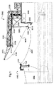
図1において、メタンタンカー1000は生産船2000に接近した状態で示されている。支持構造体2100は生産船2000に固定されている。この支持構造体2100は基本的には金属船梁で構成され、それは第2の水平セグメント2160に続いて船に固定された第1の上昇セグメント2150を有する。2つのセグメントからなるアセンブリは、水上、生産船2000の領域の外側に延びるブームを構成し、その上昇セグメントは脚部を構成している。さらに、水平セグメントの先には尖頭セグメント2170が延び、それは、生産船2000の船体から数メートル離れた距離で、水平セグメントのそれよりもわずかに高い最高点に達する。図は側面図であるため、実際には図の面に垂直な方向に互いに並んで配置されるも単独の形に見える複数の部材が存在するかもかもしれない。
In FIG. 1, the
支持構造体2100の下方部分では、連接管3000が、水平セグメント2160と尖頭セグメント2170との間の接点において支持構造体2100に固定される。連接管3000は図面の視点からは単一であるが、複数本のチューブ、特に3本のチューブが使用され、図の面に垂直な方向で互いに並んで配置されるかもしれない。
In the lower part of the
連接管3000は2つの連続したセグメントから構成され、最初に近位セグメント3100と、2番目の遠位セグメント3200から構成されている。近位セグメント3100の第1の端部は、“回転部”として知られる3つの二重旋回継手の組3110によって水平セグメント2160に連接される。そのような回転のような組み合わせにより構造体は3平面での動作(“スウェイ”、“サージ”及び“ヒーブ”の動作)が可能になる。これらの回転部の各々は二重のものであり、製品回転部と機械的回転部の両方を含んでいる。
The
近位及び遠位セグメント3100、3200の間の接合部の近傍において、連接管は、連接管の遠位構造物3200を支持構造体2100の水平セグメント2160保持するロックシステム2180によって、図1の位置に保持される。このロックシステム2180は、近位セグメント3100をブーム2100の適所に保持するシステムによって完成する。
In the vicinity of the junction between the proximal and
近位及び遠位セグメント3100、3200は、すでに引用したものと同様の単一の回転部3120によって共に連結されている。最終的には、遠位セグメント3200の自由端において、3つの回転部からなる連続物3230が、雄型センタリングコーン3220に固定された外側バルブ3210に遠位セグメント3200を接続する。
Proximal and
連接管3000は流体を搬送するための可動な管を構成する。ブームに対するその固定点は、海に張り出した地点に対し、その脚に対して水平方向数メートルだけオフセットされる。
The connecting
前述したように、図1は側面図であるために唯1本の連接管3000しか示されていないが、本発明は、図面の面に対して垂直の方向にお互いからオフセットされるか、さもなければ垂直方向に配置された複数の連接管と共に実施されるかもしれない。また本発明は1本又はそれ以上の外側ケーブルであって、その数については連接管のライン数に等しいか、或いは等しくなくとも良いような外側ケーブルと共に実施されるかもしれない。本発明はまた、1本以上の外側ケーブルと1本以上の捕捉ケーブルを伴った形で実施することも可能である。複数本のラインや複数本のケーブルを持つということは、様々な部材にかかる負荷を好ましい状態で共用でき、それらの冗長性を好適に確保したり、或いは好ましい状態でラインのバランスをとることになるかもしれない。
As described above, since FIG. 1 is a side view, only one connecting
そのエッジ部では、メタンタンカー1000は海に向かって突き出した支持構造体1100と、垂直方向に対し角度を成した軸線にセンタリングされた開口部を持った下向きの雌型センタリングコーン1110とを有する。そのコーン1110の近傍には、コーン1110に平行な向きのバルブカプラ1120がある。
At its edge, the
図1では、外側ケーブル4100が尖頭セグメント2170の端部をセンタリングコーン3220に連結させた状態で示されている。この外側ケーブル4100は、ここではそれが緩みを回避するべく最小の一定張力で保持されていることを示す点線で提示される。メタンタンカー1000の所謂“捕捉”ケーブル4200もまた、センタリングコーン3220にメタンタンカー1000の支持構造体1100を連結するものとして示されている。
In FIG. 1, the
捕捉ケーブル4200は、光メッセンジャーケーブルとウインチを使って事前に適切な場所に置かれた。これはまた外側ケーブル4100の場合である。外側ケーブル4100は、接続と切断の操作中、遠位セグメント3200の自由端の操作を目的とした操作ケーブルである。
The
図2では、メタンタンカー1000のダクトに連接管3000を接続する工程の初めの状態が示されている。
FIG. 2 shows an initial state of the process of connecting the connecting
ロックシステム2180を解除した状態で、連接管3000の動作と位置は、尖頭セグメント2170の端部にあるプーリー2171を介して、ブーム脚部2150にあるブーム2100の後端に位置するウインチ2172に漸次巻き付けられた外側ケーブル4100によって制御され、かつ近位セグメント3100と遠位セグメント3200の間の接合部近傍の近位セグメント3100の地点と、支持構造体2100の水平セグメント2160の中間近傍の地点を繋ぐ内側ケーブル4300によっても制御される。この内側ケーブル4300はウインチ2171によって操作される。両方のケーブル4100、4300は、制御された巻き付け又は巻き戻しに耐える張力下のケーブルを示す実線で図2に提示されている。これとは対照的に、捕捉ケーブル4200は依然として、図1のように連接管3000の動作や制御のためではない最小の一定張力下で操作される。
With the
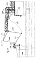
図2に提示した移動の間、支持構造体2100との取り付け地点周りで、回転運動が近位セグメント3100に与えられ、これにより同セグメントはそれまでの実質上水平配置の状態から、図3に示す垂直配置の状態へと徐々に変わっていく。当初、近位セグメント3100に対して約90°に配置されていた遠位セグメント3200は、近位セグメント3100との間に約60°の角度が形成されるまで接近する。
During the movement presented in FIG. 2, a rotational motion is imparted to the
動作継続により、図3に示された位置が達成される。ケーブル4300は、その際、最小限の一定の張力だけがそれに加わるように緩められる。その位置においては、ケーブル4300における張力の変化が連接管3000の2部品の位置に影響を及ぼさないため、図3の位置が平衡位置としての資格がある。この位置では、外側ケーブル4100は実質的に垂直である。
By continuing the operation, the position shown in FIG. 3 is achieved. The
この段階で、メタンタンカー1000の支持構造体1100のウインチ1130は、捕捉ケーブル4100を巻き付けるように駆動される。数分後、プーリー2171の周りで回転する外側ケーブル4100を制御する巻取りウインチ2172は駆動停止されており、その際最小の一定張力だけが外側ケーブル4100に付与される。その移動は継続するため、雄型コーン3220は雌型コーンで1110に係合し、外側バルブ3210は、バルブカプラ1120の下方バルブに接続する。ウインチ1130はその後駆動停止されるか、或いは捕捉ケーブル4200が切断され、緊急時、シースを解放可能な油圧ハサミを使って捕捉ケーブルの鞘が切断される。物理的には、ケーブルに圧着される鞘はそれらのケーシング内に残るが、もはやロックはされない。
At this stage, the
接続後は、最小の一定の張力だけが外側ケーブル4100と内部ケーブル4300にかかる。
After connection, only the minimum constant tension is applied to the
図6では、ダクトの間の接合部は生産船2000によってもたらされ、メタンタンカー1000からのダクトは図5の位置にある。
In FIG. 6, the junction between the ducts is provided by the
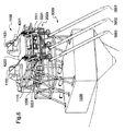
この7分身図は、先の図で提示された管3000と同じ種類の、それぞれ互いに平行な3連接管と、同様に先の図面で提示されや捕捉ケーブル400と同じ種類の、同様に互いに平行な2本の捕捉ケーブルの存在することを示している。連接管は夫々、参照番号3001、3002及び3003を持ち、捕捉ケーブルは夫々参照番号4201及び4203を持つ。
This 7-part view is of the same type as the
連接管3001、3002及び3003は、横方向の保持構造体3020によって互いに接合されている。2つの雄型センタリングコーン3221、3223は、その横方向保持構造体3020に対して上方に固定されている。雌型センタリングコーン1110と同じ種類の2つの雌型センタリングコーン1111、1113は支持構造体1100に下方に固定されている。雄型センタリングコーン3221と3223は、示された構成において雌型センタリングコーン1111、1113に夫々係合する。
The connecting
捕捉ケーブル4201、4203はプーリーを介し、先の図で提示したウインチ1130と同じ種類のウインチ1131、1133で制御される。各捕捉ケーブルは、1組のセンタリングコーンを通り、鞘とハサミによって接続されている横方向保持構造体3020に接触する。
The
ウインチ1131、ケーブル4201、コーン1111及び3221、管3001とバルブカプラ及びその接続のための外側バルブは第1の平面内にあり、ウインチ1133、ケーブル4203、コーン1113及び3223、管3003、バルブカプラ及びその接続のための外側バルブは前記第1の平面と平行な第2の平面内にある。これら2つの平面の間に位置するのが管3002、バルブカプラ及びその接続のための外側バルブである。
The
安全ケーブル1210(不可視)を制御するウインチ1200も見ることができる。安全ケーブル1210は、メタンタンカーの3つのバルブカプラの下部に常時取り付けられている(バルブカプラの構造については以下の段落を参照されたい)。
A
1つのバルブカプラ1120の側面図である図7からわかるように、同バルブカプラは下方バルブ1121と上方バルブ1122によって構成される。バルブカプラ1120には更に、緊急分離の際、下方バルブ1121を、ヒンジ連結ラインの外側バルブ3210に接続されたままで上方バルブ1122から取り外す緊急解除システム1128(緊急解除システムとしてのERS、又は電動緊急解除カプラとしてのPERC)が設けられる。ウインチ1200(図6)は、その際、連接ラインの遠位セグメント3200の自由端の落下(図13〜16で説明した想定事例)を示す安全ケーブル1210(不可視)の巻き戻しに対するブレーキを構成する。
As can be seen from FIG. 7 which is a side view of one
連接管3001、3002及び3003は、特に横方向保持構造体3020により、全体としてケーブルとは無関係な状態で、それぞれ互いに迅速に保持される。このように3本の連接管がある場合、2本の捕捉ケーブル4201、4203だけが使用される。また、2組のガイドコーンだけを使用することができる。同様に、たった2本の外側ケーブル4100が使用され(図6乃至図8には示されていない)、たった2本だけの内部ケーブル4300が使用される。安全ケーブル1210に関しては、これは単一のものであり、3つのバルブカプラを組み込んだ剛性構造体により、その中央に位置するバルブカプラに連結される。
The connecting
図7は、捕捉ケーブルと係合コーンに対面して配置された2本の連接管3000の内の一方(図6では、管3001又は管3003のどちらかが関係する)を示している。この管は一連の3つの連続する回転部3220によって、雄型センタリングコーン3220に係合する雌型コーン1110に平行な、バルブカプラの下方バルブ1121に係合する外側バルブ3210に連結される。ここでは、雄型センタリングコーン3220に隣接し、それに対して堅固に連結される構造体に接続される外側ケーブル4100も見ることができる。参照番号1125は、緊急解除システム1128に反して、結合にあたって手動操作を必要としない通常の接続/分離状況で使用される油圧結合部材を示している。
FIG. 7 shows one of the two connecting tubes 3000 (facing either
図8はダクトを分離した同一構造体を示している。雄型センタリングコーン3220は図7におけるそれよりも一層明確になっている。
FIG. 8 shows the same structure with the ducts separated. The
重要なことは、一連の回転部3220を越えて連接管3000に対しケーブル4100が固定された際、外側バルブ3210の口は、あらゆる状況で上方を向くことである。
Importantly, when the
他の実施形態において、ダクトは可撓性ホースから構成されるかもしれず、その場合には、一連の3つの回転部3220が存在しない場合もある。そのような場合に備え、本発明はさらに、外側バルブ3210に堅固に固定されることになるケーブル4100を提供し、口を上方に向けるような制御を可能にする。回転部はバルブカプラ1120の上方、つまりメタンタンカー1000に存在するかもしれない。
In other embodiments, the duct may be composed of a flexible hose, in which case the series of three
図8に示された分離を開始するための移動に加え、図7の位置から始まり、図9に示すように完全なる分離手順が実行される。まず最初に捕捉ケーブル4200が再接続される。
In addition to the movement for starting the separation shown in FIG. 8, starting from the position of FIG. 7, the complete separation procedure is performed as shown in FIG. First, the
このようにして、一旦バルブカプラ1120及び外側バルブ3210が互いからロック解除されたならば、ウインチ1130が作動されて捕捉ケーブル4200を巻き戻す。このような巻き戻しは数メートルに亘って一定速度で行われる。この段階で外側ケーブル4100と内側ケーブル4300ケーブルは最小限の一定張力で保持され、それが弛んでしまうのを防止する。図10において、ウインチ2172は、一定の長さの外側ケーブル4100を提供するようにしてロックされる。ウインチ1200によって捕捉ケーブル4200が一定速度で巻き戻される一方で、内側ケーブル4300は最小の一定張力に保持される。
In this way, once the
その動作は連接管3000が図11にしたその平衡位置に到達するまで続行される。この平衡位置は、その位置において捕捉ケーブル4200の弛みが連接チューブ3000の動作や位置に影響を及ぼさないこと、という事実によって定義される。捕捉ケーブル4200はその後、連接チューブ3000の自由端からは取り外され、それと同時か或いは少し遅れた形でウインチ2161による内側ケーブル4300の巻き付けが開始される。又、図11の配置では、ウインチ2172のロックが解除され、連接管300全体をそのパーキング位置に連れて行くように外側ケーブル4100の長さが調整される。
The operation continues until the connecting
このようにして、図12では、近位セグメント3100が実質的に水平位置に戻ると共に遠位セグメント3200が実質的に垂直位置まで戻り、ロックシステム2180は遠位セグメント3200への作用が可能となり、内側ケーブル4300の長さは実質的にゼロ長さまで減じされ、外側ケーブル4100は最小の一定張力下に制御される。
Thus, in FIG. 12, the
一旦、連接管3000がパーキング位置又は静止位置に置かれたならば、外側ケーブルは巻き付けられ、簡単なメッセンジャーケーブルがプーリー2171と連接管3000の自由端との間に保持される。
Once the connecting
以下、生産船2000のダクトとメタンタンカー1000のダクトの緊急時の切り離しについて説明する。尚、これらのダクトは図5 、図6及び図7では連結した状態で示されている。そのような緊急時の切り離しは、例えば図13に示すように、メタンタンカー1000が生産船2000から遠く離れすぎて移動する際に、自動的又は手動で開始される。
Hereinafter, the emergency disconnection of the duct of the
緊急時切り離し処置のスタート時点において、外側ケーブル4100を作動するウインチ2172は、そのケーブルが一定の長さを維持するようにロックされ、それにより遠位セグメント3200の自由端が水中に落下しないのを確実にする。即ち、外側ケーブル又はケーブル4100の長さは、水の外に遠位部分3200の自由端(スタイル80と呼ばれる)を維持するように、緊急切り離しの開始後、数秒間、ロック装置やブレーキを作動することで固定される。内側ケーブル4300は緩みを回避するべく最小の一定張力に維持され続ける。PERC(電動緊急リリースカプラー)1128が切断されることでバルブ121及び1122(図7、図8参照)は分離し、コーン1110及び3220は互いに離れていく。図14に見られるように、制動作用の観点から安全ケーブル1210は例えば3メートル/秒に等しい程の最大速度で巻き戻される。冒頭の接続処置の終了時点では、遠位セグメント3200の自由端において捕捉ケーブル4200(図示せず)は予め分離されていたことに留意されたい。
At the start of the emergency disconnection procedure, the
しばらくすると、図15に見られるように安全ケーブル1210の全長が巻き戻され、それはウインチ1200のドラムから単独で分離する。この段階では、外側ケーブル4100は実質的に垂直位置に戻り、近位セグメント3100は実質的に垂直な位置を取り戻す一方、遠位セグメント3200は実質的に水平な配置をとる。
After a while, the entire length of the
切り離しにあたって採用されたその動作の影響下で、連接管3000全体は、図16に見られるように生産船2000に近づく。獲得された速度はウインチ1200の制動作用により特に低いため、その動作は制御される。制動が内側ケーブル4300のウインチ2161に加えられ、その後制動解放される。内側ケーブル4300は、その後、一定速度で巻き付けられる。外側ケーブル4100も又、一定速度で巻き戻される。2本のケーブル4300、4100を操作することで連接管はそのパーキング位置へと戻され、その後の操作に関しては従来の切り離し手順と同様である。
Under the influence of the operation adopted in the separation, the whole connecting
本発明は開示した実施形態に限定されず、請求の範囲内において当業者の能力の範囲内にあるすべての変形例を包含するものである。 The invention is not limited to the disclosed embodiments, but is intended to cover all modifications that are within the scope of those skilled in the art within the scope of the claims.
Claims (19)
内側操作ケーブル(4300)と呼ばれる第2の操作ケーブルが、前記可動な流体搬送管(3000)の中間点を前記ブームに連結することを特徴とする海上流体移送システム。 A marine fluid transfer system having a boom (2100) and at least one movable fluid transport tube (3000) attached to the boom, the movable fluid transport tube (3000) starting from its anchor point; A length of extension, an outer valve (3210) for coupling to a third party loading tube, an outer operating cable (4100) operated from the boom (2100), and a cable anchor point; The cable anchor point for securing the outer operating cable (4100) to the outer valve (3210), the operating cable connected to the free end of the movable fluid carrying tube at a point called 3210) in a maritime fluid transfer system,
A marine fluid transfer system, wherein a second operation cable called an inner operation cable (4300) connects an intermediate point of the movable fluid conveyance pipe (3000) to the boom.
前記可動な流体搬送管(3000)は、アンカーポイントから始めて、第三者の装填管に結合するための外側バルブ(3210)がその後に続く一定の長さの延長部を有し、結合又は分離のための一般的な操作は、前記ブーム(2100)によって操縦されかつケーブルアンカーポイントと呼ばれるポイントで前記可動な流体搬送管の自由端に連結された外側操作ケーブル(4100)を用いて可動な流体搬送管(3000)を延伸させる又は夫々を収縮させるステップを有し、
前記外側操作ケーブル(4100)を前記外側バルブ(3210)に固定する前記ケーブルアンカーポイントは前記外側バルブ(3210)に堅固に接続されている、方法において、
前記可動な流体搬送管(3000)を延伸させる又は夫々を収縮させるステップは、内側操作ケーブル(4300)と呼ばれる第2の操作ケーブルを少なくとも使用し、前記可動な流体搬送管(3000)の中間点を前記ブームに連結することによって実行されることを特徴とする海上流体移送方法。 A method of fluid transfer at sea by at least one movable fluid transfer tube (3000) attached to a boom (2100),
The movable fluid carrying tube (3000) has a length of extension, starting from an anchor point, followed by an outer valve (3210) for coupling to a third party loading tube, coupled or separated The general operation for is to move fluid using an outer operating cable (4100) that is steered by the boom (2100) and connected to the free end of the movable fluid carrying tube at a point called the cable anchor point. Stretching the transport tubes (3000) or shrinking each one;
The method, wherein the cable anchor point that secures the outer operating cable (4100) to the outer valve (3210) is rigidly connected to the outer valve (3210);
The step of extending or contracting each of the movable fluid conveyance pipes (3000) uses at least a second operation cable called an inner operation cable (4300), and is an intermediate point of the movable fluid conveyance pipe (3000). A marine fluid transfer method, characterized in that it is carried out by connecting the boom to the boom.
メッセンジャーケーブルを用いて捕捉ケーブルを配置するステップと、
前記外側操作ケーブルを巻いて前記内側操作ケーブルを解いて前記捕捉ケーブルを最小の一定張力下に保つステップと、
前記内側操作ケーブルにおける張力の変化が前記管の位置に影響を及ぼさず、その時に前記外側操作ケーブルが実質的に垂直となるように、前記内側操作ケーブルに最小の一定張力だけが付与されるように、前記内側操作ケーブルを緩めるステップと、
前記捕捉ケーブルを巻くステップと、
前記外側操作ケーブルを巻くステップを停止し、前記外側操作ケーブルに最小の一定張力を加えるステップとを備えていることを特徴とする請求項12に記載の海上流体移送方法。 The stretching step includes
Placing the capture cable using a messenger cable;
Winding the outer operating cable and unwinding the inner operating cable to keep the capture cable under a minimum constant tension;
Only a minimum constant tension is applied to the inner operating cable such that a change in tension in the inner operating cable does not affect the position of the tube, at which time the outer operating cable is substantially vertical. A step of loosening the inner operation cable;
Winding the capture cable;
The step of winding the outer operating cable is stopped, and a step of applying a minimum constant tension to the outer operating cable is provided.
前記捕捉ケーブルを一定の速度で解きつつ、前記外側操作ケーブル及び前記内側操作ケーブルの緩みを回避するように前記外側操作ケーブル及び前記内側操作ケーブルを最小の一定張力に保つステップと、
一定長さの前記外側操作ケーブルを付与するステップと、
前記捕捉ケーブルを一定の速度で解きつつ、前記内側操作ケーブルを最小の一定張力に保つステップと、
前記捕捉ケーブルの緩みが前記管の運動又は位置に影響を及ぼさない時に前記捕捉ケーブルを前記管から取り外すステップと、
前記内側操作ケーブルを巻いて前記管をパーキング位置に連れて行くように前記外側操作ケーブルの長さを制御するステップとを備えていることを特徴とする請求項12に記載の海上流体移送方法。 The contracting step includes:
Maintaining the outer and inner operating cables at a minimum constant tension so as to avoid loosening of the outer and inner operating cables while unwinding the capture cable at a constant speed;
Applying the outer operating cable of a certain length;
Unwinding the capture cable at a constant speed while keeping the inner operating cable at a minimum constant tension;
Removing the capture cable from the tube when a slack in the capture cable does not affect the movement or position of the tube;
The marine fluid transfer method according to claim 12, further comprising the step of controlling the length of the outer operation cable so as to wind the inner operation cable and take the pipe to a parking position.
前記捕捉ケーブルを一定の速度で解きつつ、前記外側操作ケーブル及び前記内側操作ケーブルの緩みを回避するように前記外側操作ケーブル及び前記内側操作ケーブルを最小の一定張力に保つステップと、
一定長さの前記外側操作ケーブルを付与するステップと、
前記捕捉ケーブルを一定の速度で解きつつ、前記内側操作ケーブルを最小の一定張力に保つステップと、
前記捕捉ケーブルの緩みが前記管の運動又は位置に影響を及ぼさない時に前記捕捉ケーブルを前記管から取り外すステップと、
前記内側操作ケーブルを巻いて前記管をパーキング位置に連れて行くように前記外側操作ケーブルの長さを制御するステップとを備え、
緊急切り離しの処置において、前記外側操作ケーブルは一定の長さで確保され、前記内側操作ケーブルは、前記内側操作ケーブルの緩みを回避するように最小の一定張力で保たれ、緊急分離システムが作動させられ、前記安全ケーブルが、前記安全ケーブルが巻かれているウィンチのドラムから単独で分離するまで、前記安全ケーブルが安全性最大速度よりも遅い速度で解かれ、前記内側操作ケーブルが一定の速度で巻かれ、前記外側操作ケーブルが、前記管をパーキング位置に連れて行くように一定の速度で解かれることを特徴とする請求項14に記載の海上流体移送方法。 The contracting step includes:
Maintaining the outer and inner operating cables at a minimum constant tension so as to avoid loosening of the outer and inner operating cables while unwinding the capture cable at a constant speed;
Applying the outer operating cable of a certain length;
Unwinding the capture cable at a constant speed while keeping the inner operating cable at a minimum constant tension;
Removing the capture cable from the tube when a slack in the capture cable does not affect the movement or position of the tube;
Winding the inner operation cable and controlling the length of the outer operation cable to take the tube to a parking position;
In the emergency disconnection procedure, the outer operating cable is secured with a certain length, the inner operating cable is kept at a minimum constant tension to avoid loosening of the inner operating cable, and the emergency separating system is activated. Until the safety cable is separated from the winch drum around which the safety cable is wound, the safety cable is unfastened at a speed lower than the maximum safety speed, and the inner operating cable is at a constant speed. rolled, said outer operating cable, marine fluid transfer method according to claim 1 4, characterized in that to be solved at a constant speed so take the tube to the parking position.
Applications Claiming Priority (3)
| Application Number | Priority Date | Filing Date | Title |
|---|---|---|---|
| FR1153138A FR2973771B1 (en) | 2011-04-11 | 2011-04-11 | SYSTEM AND METHOD FOR OFFSHORE FLUID TRANSFER |
| FR1153138 | 2011-04-11 | ||
| PCT/IB2012/051743 WO2012140566A1 (en) | 2011-04-11 | 2012-04-10 | Offshore fluid transfer system and method |
Publications (2)
| Publication Number | Publication Date |
|---|---|
| JP2014516328A JP2014516328A (en) | 2014-07-10 |
| JP6208656B2 true JP6208656B2 (en) | 2017-10-04 |
Family
ID=46052832
Family Applications (1)
| Application Number | Title | Priority Date | Filing Date |
|---|---|---|---|
| JP2014504425A Active JP6208656B2 (en) | 2011-04-11 | 2012-04-10 | Marine fluid transfer system and method |
Country Status (15)
| Country | Link |
|---|---|
| US (1) | US9644764B2 (en) |
| EP (1) | EP2697112B1 (en) |
| JP (1) | JP6208656B2 (en) |
| KR (1) | KR102002182B1 (en) |
| CN (1) | CN103608259B (en) |
| AU (1) | AU2012241481B2 (en) |
| BR (1) | BR112013026056B1 (en) |
| CA (1) | CA2832423C (en) |
| FR (1) | FR2973771B1 (en) |
| MX (1) | MX2013011925A (en) |
| MY (1) | MY164535A (en) |
| RU (1) | RU2598127C2 (en) |
| SG (1) | SG11201404951XA (en) |
| WO (1) | WO2012140566A1 (en) |
| ZA (1) | ZA201308333B (en) |
Families Citing this family (24)
| Publication number | Priority date | Publication date | Assignee | Title |
|---|---|---|---|---|
| CN103542252B (en) * | 2013-09-30 | 2015-10-28 | 江苏现代造船技术有限公司 | The filling apparatus of a kind of LNG |
| FR3018766B1 (en) * | 2014-03-24 | 2016-04-01 | Gaztransp Et Technigaz | SYSTEM FOR THE TRANSFER OF FLUID BETWEEN VESSEL AND A FACILITY, SUCH AS A CLIENT SHIP |
| CN104085704B (en) * | 2014-06-23 | 2016-06-15 | 中国海洋石油总公司 | A kind of FLNG outer transfer device of string based on telescopic rigid pipe |
| CN104085705A (en) * | 2014-06-23 | 2014-10-08 | 中国海洋石油总公司 | FLNG tandem transportation device based on rotary-disc type hose |
| CN104554689B (en) * | 2015-02-03 | 2016-09-28 | 重庆燃气集团股份有限公司 | A kind of method to landing stage supply natural gas |
| CN104590494B (en) * | 2015-02-15 | 2017-03-01 | 中国人民解放军总后勤部油料研究所 | One kind no harbour oil tanker offshore oil transportation method |
| GB2537673A (en) * | 2015-04-24 | 2016-10-26 | Houlder Ltd | Deployable connection and emergency release system |
| JP6545023B2 (en) * | 2015-07-15 | 2019-07-17 | 川崎重工業株式会社 | Liquid hydrogen loading arm and liquid hydrogen transfer method |
| CN106005276B (en) * | 2016-05-19 | 2017-12-01 | 武汉船用机械有限责任公司 | Marine liquid goods feeds conveying device |
| FR3051782B1 (en) * | 2016-05-24 | 2018-07-06 | Fmc Technologies Sa | DISPLACEMENT CONTROL DEVICE, ACQUISITION AND CALCULATION METHOD AND DEVICE THEREFOR, AND ARTICULATED FLUID LOADING ARM COMPRISING SAME. |
| JP6855510B2 (en) * | 2016-06-22 | 2021-04-07 | エフエムセ テクノロジーズ | Retractable bow loading system and method |
| CN106439484B (en) * | 2016-07-01 | 2019-07-12 | 韩培 | Low temperature two-tube loading arm peculiar to vessel |
| WO2019046624A1 (en) | 2017-08-30 | 2019-03-07 | Oil States Industries, Inc. | Loading arm system |
| NO343762B1 (en) | 2017-10-17 | 2019-06-03 | Cefront Tech As | Loading hose Connection assembly |
| CN110360443A (en) * | 2018-04-11 | 2019-10-22 | 江苏蓝色船舶动力有限公司 | A kind of bank gas station for object ship filling LNG |
| FR3083791B1 (en) * | 2018-07-12 | 2020-08-28 | Gaztransport Et Technigaz | LIQUEFIED GAS TRANSFER SYSTEM |
| CN109553058B (en) * | 2019-01-08 | 2020-08-04 | 天津辰力工程设计有限公司 | Low-temperature propane ship unloading and heating process |
| WO2020206259A1 (en) * | 2019-04-05 | 2020-10-08 | Sofec, Inc. | Disconnectable tower yoke mooring system and methods for using same |
| SG11202111062RA (en) | 2019-04-05 | 2021-11-29 | Sofec Inc | Disconnectable tower yoke mooring system and methods for using same |
| SG11202113054QA (en) * | 2019-05-29 | 2021-12-30 | Sofec Inc | Systems for handling one or more elongated members and methods for using same |
| WO2021034828A1 (en) | 2019-08-19 | 2021-02-25 | Sofec, Inc. | Mooring systems and processes for using same |
| KR20220092976A (en) | 2019-11-08 | 2022-07-04 | 소펙, 인크. | Surge damping systems and processes using them |
| WO2021092377A1 (en) | 2019-11-08 | 2021-05-14 | Sofec, Inc. | Mooring support structures, systems for mooring vessels, and processes for using same |
| NO346638B1 (en) * | 2020-02-21 | 2022-11-07 | Well Cleanup AS | A method and a system for transferring fluid |
Family Cites Families (29)
| Publication number | Priority date | Publication date | Assignee | Title |
|---|---|---|---|---|
| US1680831A (en) | 1924-06-24 | 1928-08-14 | White Walter Carman | Fluid-conveying apparatus |
| US3032082A (en) * | 1959-10-14 | 1962-05-01 | Vilain Charles | Loading and discharging installation for oil-tankers |
| US3085593A (en) | 1960-05-19 | 1963-04-16 | Harry E Sorensen | Cargo transfer apparatus |
| US3249121A (en) | 1963-04-10 | 1966-05-03 | Fmc Corp | Fluid conveying apparatus |
| US3217748A (en) * | 1963-06-26 | 1965-11-16 | John D Harper | Flexible insulated fluid transfer apparatus |
| US3773093A (en) * | 1972-03-20 | 1973-11-20 | G Eustace | Bow liquid cargo handling system |
| SU553162A1 (en) * | 1975-05-14 | 1977-04-05 | Специальное конструкторское бюро "Транснефтеавтоматика" | Device for discharging liquid products into the vessel |
| FR2368434A1 (en) * | 1976-10-19 | 1978-05-19 | Emh | IMPROVEMENTS IN EQUIPMENT SERVING TO CONNECT OIL VESSELS TO MARINE COLUMNS |
| FR2368399A1 (en) | 1976-10-19 | 1978-05-19 | Emh | IMPROVEMENTS TO EQUIPMENT TO CONNECT OIL TANKERS TO MARINE OR SIMILAR COLUMNS |
| US4261398A (en) * | 1979-06-13 | 1981-04-14 | Fmc Corporation | Deepwater offshore loading apparatus |
| US4408943A (en) | 1981-02-27 | 1983-10-11 | Fmc Corporation | Ship-to-ship fluid transfer system |
| FR2638731B1 (en) * | 1988-11-09 | 1991-02-08 | Fmc Europe | METHOD FOR PROVIDING A DISCONNECTION BETWEEN A FLUID LOADING ARM AND A TANK, ONE OF WHICH IS CARRIED BY A VEHICLE IN THE EVENT OF AN UNEXPECTED DEPARTURE OF THE VEHICLE; FLUID LOADING ARM IMPLEMENTING THIS PROCESS; SAFETY DISCONNECTOR FOR ITS IMPLEMENTATION |
| US4989903A (en) * | 1989-07-21 | 1991-02-05 | The United States Of America As Represented By The Secretary Of The Navy | Flexible flow through saddle |
| NO308105B1 (en) * | 1998-01-06 | 2000-07-24 | Kvaerner Maritime As | Device for transferring very cold fluids from a platform to a vessel |
| NO315194B1 (en) | 1998-01-30 | 2003-07-28 | Navion As | Process and system for export of LNG and condensate from a floating production, storage and unloading vessel |
| EP0947464A1 (en) | 1998-04-01 | 1999-10-06 | Single Buoy Moorings Inc. | Fluid transfer boom with coaxial fluid ducts |
| FR2793235B1 (en) | 1999-05-03 | 2001-08-10 | Fmc Europe | ARTICULATED DEVICE FOR TRANSFERRING FLUID AND LOADING CRANE COMPRISING SUCH A DEVICE |
| NO312715B2 (en) | 1999-10-27 | 2002-06-24 | Statoil Asa | System for offshore transmission of liquefied natural gas |
| FR2813872B1 (en) * | 2000-09-14 | 2003-01-31 | Fmc Europe | ARTICULATED ARM FOR LOADING AND UNLOADING PRODUCTS, PARTICULARLY FLUID PRODUCTS |
| FR2815025B1 (en) | 2000-10-06 | 2003-08-29 | Eurodim Sa | SYSTEM FOR TRANSFERRING A FLUID PRODUCT, IN PARTICULAR LIQUEFIED NATURAL GAS AT CRYOGENIC TEMPERATURE, BETWEEN A TRANSPORT VESSEL AND A LAND TREATMENT AND STORAGE FACILITY FOR THIS PRODUCT |
| FR2824529B1 (en) * | 2001-05-11 | 2003-08-29 | Eurodim Sa | SYSTEM FOR TRANSFERRING A FLUID PRODUCT, ESPECIALLY LIQUEFIED GAS, BETWEEN A TRANSPORT VEHICLE SUCH AS A VESSEL AND A RECEPTION OR SUPPLY FACILITY FOR THIS PRODUCT |
| AU2003287647A1 (en) | 2002-11-12 | 2004-06-03 | Fmc Technologies, Inc. | Retrieval and connection system for a disconnectable mooring yoke |
| FR2854156B1 (en) * | 2003-04-23 | 2007-03-09 | Fmc Technologies Sa | ARTICULATED-ARM ASSEMBLY COMPRISING A CONNECTING CABLE FOR LOADING AND UNLOADING PRODUCTS, IN PARTICULAR FLUID PRODUCTS |
| WO2005105565A1 (en) | 2004-04-29 | 2005-11-10 | Single Buoy Moorings Inc. | Side-by-side hydrocarbon transfer system |
| EP1999009B1 (en) * | 2006-03-30 | 2011-08-17 | Single Buoy Moorings Inc. | Hydrocarbon transfer system with vertical rotation axis |
| FR2914903B1 (en) * | 2007-04-12 | 2010-05-28 | Technip France | DEVICE FOR TRANSFERRING A FLUID TO A VESSEL, SHIP, TRANSFER ASSEMBLY AND ASSOCIATED METHOD |
| FR2937628A1 (en) * | 2008-10-23 | 2010-04-30 | Nereus Technologies | CABLE CUTTING SAFETY DEVICE OR EXPLOSIVE CORDING |
| FR2941434B1 (en) * | 2009-01-27 | 2015-05-01 | Fmc Technologies Sa | SYSTEM FOR TRANSFERRING A FLUID PRODUCT AND ITS IMPLEMENTATION |
| NO337059B1 (en) * | 2009-05-25 | 2016-01-11 | Aker Pusnes As | coupling device |
-
2011
- 2011-04-11 FR FR1153138A patent/FR2973771B1/en not_active Expired - Fee Related
-
2012
- 2012-04-10 CA CA2832423A patent/CA2832423C/en active Active
- 2012-04-10 EP EP12720280.2A patent/EP2697112B1/en active Active
- 2012-04-10 WO PCT/IB2012/051743 patent/WO2012140566A1/en active Application Filing
- 2012-04-10 CN CN201280025525.XA patent/CN103608259B/en active Active
- 2012-04-10 JP JP2014504425A patent/JP6208656B2/en active Active
- 2012-04-10 SG SG11201404951XA patent/SG11201404951XA/en unknown
- 2012-04-10 MY MYPI2013003681A patent/MY164535A/en unknown
- 2012-04-10 US US14/111,528 patent/US9644764B2/en active Active
- 2012-04-10 MX MX2013011925A patent/MX2013011925A/en not_active Application Discontinuation
- 2012-04-10 AU AU2012241481A patent/AU2012241481B2/en active Active
- 2012-04-10 KR KR1020137028671A patent/KR102002182B1/en active IP Right Grant
- 2012-04-10 BR BR112013026056-4A patent/BR112013026056B1/en active IP Right Grant
- 2012-04-10 RU RU2013150076/11A patent/RU2598127C2/en active
-
2013
- 2013-11-06 ZA ZA2013/08333A patent/ZA201308333B/en unknown
Also Published As
| Publication number | Publication date |
|---|---|
| CA2832423A1 (en) | 2012-10-18 |
| EP2697112A1 (en) | 2014-02-19 |
| EP2697112B1 (en) | 2016-08-17 |
| KR20140026443A (en) | 2014-03-05 |
| CA2832423C (en) | 2019-06-18 |
| BR112013026056A2 (en) | 2017-02-14 |
| US9644764B2 (en) | 2017-05-09 |
| SG11201404951XA (en) | 2014-11-27 |
| FR2973771B1 (en) | 2015-07-17 |
| CN103608259A (en) | 2014-02-26 |
| ZA201308333B (en) | 2014-08-27 |
| MY164535A (en) | 2017-12-29 |
| WO2012140566A1 (en) | 2012-10-18 |
| AU2012241481B2 (en) | 2016-05-26 |
| FR2973771A1 (en) | 2012-10-12 |
| KR102002182B1 (en) | 2019-07-19 |
| RU2013150076A (en) | 2015-05-20 |
| AU2012241481A1 (en) | 2013-10-31 |
| JP2014516328A (en) | 2014-07-10 |
| US20140034137A1 (en) | 2014-02-06 |
| MX2013011925A (en) | 2013-11-01 |
| BR112013026056B1 (en) | 2021-04-13 |
| CN103608259B (en) | 2017-06-09 |
| RU2598127C2 (en) | 2016-09-20 |
Similar Documents
| Publication | Publication Date | Title |
|---|---|---|
| JP6208656B2 (en) | Marine fluid transfer system and method | |
| EP2678216B1 (en) | System for transferring a fluid, especially liquefied petroleum gas, between a first surface installation and a second surface installation | |
| AU2010253533B2 (en) | Coupling device | |
| JP5613192B2 (en) | Hinge joint arm assembly for loading and unloading products, particularly fluid products | |
| AU2010209420B2 (en) | System for transferring a fluid product and its implementation | |
| JP4275416B2 (en) | Fluid product transfer system. | |
| JPH10507709A (en) | Method and apparatus for transferring offshore oil | |
| WO2016135487A1 (en) | Fluid transfer system and method for carrying out fluid transfer |
Legal Events
| Date | Code | Title | Description |
|---|---|---|---|
| A621 | Written request for application examination |
Free format text: JAPANESE INTERMEDIATE CODE: A621 Effective date: 20150318 |
|
| A131 | Notification of reasons for refusal |
Free format text: JAPANESE INTERMEDIATE CODE: A131 Effective date: 20160315 |
|
| A977 | Report on retrieval |
Free format text: JAPANESE INTERMEDIATE CODE: A971007 Effective date: 20160317 |
|
| A601 | Written request for extension of time |
Free format text: JAPANESE INTERMEDIATE CODE: A601 Effective date: 20160609 |
|
| A521 | Request for written amendment filed |
Free format text: JAPANESE INTERMEDIATE CODE: A523 Effective date: 20160914 |
|
| A131 | Notification of reasons for refusal |
Free format text: JAPANESE INTERMEDIATE CODE: A131 Effective date: 20170228 |
|
| A521 | Request for written amendment filed |
Free format text: JAPANESE INTERMEDIATE CODE: A523 Effective date: 20170525 |
|
| TRDD | Decision of grant or rejection written | ||
| A01 | Written decision to grant a patent or to grant a registration (utility model) |
Free format text: JAPANESE INTERMEDIATE CODE: A01 Effective date: 20170808 |
|
| A61 | First payment of annual fees (during grant procedure) |
Free format text: JAPANESE INTERMEDIATE CODE: A61 Effective date: 20170907 |
|
| R150 | Certificate of patent or registration of utility model |
Ref document number: 6208656 Country of ref document: JP Free format text: JAPANESE INTERMEDIATE CODE: R150 |
|
| R250 | Receipt of annual fees |
Free format text: JAPANESE INTERMEDIATE CODE: R250 |
|
| R250 | Receipt of annual fees |
Free format text: JAPANESE INTERMEDIATE CODE: R250 |
|
| R250 | Receipt of annual fees |
Free format text: JAPANESE INTERMEDIATE CODE: R250 |
|
| R250 | Receipt of annual fees |
Free format text: JAPANESE INTERMEDIATE CODE: R250 |