JP6207301B2 - Optical deflection device - Google Patents

Optical deflection device Download PDF

Info

Publication number
JP6207301B2
JP6207301B2 JP2013172648A JP2013172648A JP6207301B2 JP 6207301 B2 JP6207301 B2 JP 6207301B2 JP 2013172648 A JP2013172648 A JP 2013172648A JP 2013172648 A JP2013172648 A JP 2013172648A JP 6207301 B2 JP6207301 B2 JP 6207301B2
Authority
JP
Japan
Prior art keywords
rotor
stator
rotation axis
optical
protrusion
Prior art date
Legal status (The legal status is an assumption and is not a legal conclusion. Google has not performed a legal analysis and makes no representation as to the accuracy of the status listed.)
Active
Application number
JP2013172648A
Other languages
Japanese (ja)
Other versions
JP2015041013A (en
Inventor
浩之 福原
浩之 福原
Current Assignee (The listed assignees may be inaccurate. Google has not performed a legal analysis and makes no representation or warranty as to the accuracy of the list.)
Canon Inc
Original Assignee
Canon Inc
Priority date (The priority date is an assumption and is not a legal conclusion. Google has not performed a legal analysis and makes no representation as to the accuracy of the date listed.)
Filing date
Publication date
Application filed by Canon Inc filed Critical Canon Inc
Priority to JP2013172648A priority Critical patent/JP6207301B2/en
Publication of JP2015041013A publication Critical patent/JP2015041013A/en
Application granted granted Critical
Publication of JP6207301B2 publication Critical patent/JP6207301B2/en
Active legal-status Critical Current
Anticipated expiration legal-status Critical

Links

Images

Landscapes

  • Laser Beam Printer (AREA)
  • Mechanical Optical Scanning Systems (AREA)
  • Sliding-Contact Bearings (AREA)
  • Facsimile Scanning Arrangements (AREA)

Description

本発明は、レーザビームプリンタやデジタル複写機、デジタルFAX等の画像形成装置に用いられる光学走査装置のレーザビームを偏向走査するための光偏向装置に関するものである。   The present invention relates to an optical deflecting device for deflecting and scanning a laser beam of an optical scanning device used in an image forming apparatus such as a laser beam printer, a digital copying machine, or a digital FAX.

画像形成装置用の光学走査装置の光偏向装置の中には、流体軸受を用いたアウターロータ型モータによって回転多面鏡を回転させるものがある。   Some optical deflectors of an optical scanning device for an image forming apparatus rotate a rotating polygon mirror by an outer rotor type motor using a fluid bearing.

このような光偏向装置における、ロータの抜け止め構造として、特許文献1には、モータを支持する鉄製の回路基板部材の一部を曲げ起こして抜け止め部を設け、ロータが抜けようとした際に抜け止め部がロータフレームの外側部分に当接することで、ロータが抜けることを規制する構成が開示されている。また、特許文献2には、モータを支持する基板に、基板とは別部材の抜け止め部材を取り付けることにより、抜け止め部を設けた構成が開示されている。   As a rotor retaining structure in such an optical deflecting device, Patent Document 1 discloses that a part of an iron circuit board member that supports a motor is bent and provided with a retaining part so that the rotor is about to come off. A configuration is disclosed in which the stopper prevents the rotor from coming off by contacting the outer portion of the rotor frame. Patent Document 2 discloses a configuration in which a retaining portion is provided by attaching a retaining member, which is a member different from the substrate, to a substrate that supports a motor.

特開平11−183829JP-A-11-183829 特開2008−39148JP 2008-39148 A

しかしながら、特許文献1にように、基板部材の一部を曲げ起こす場合、曲げ起こす工程が必要になるため、組み立て工程が煩雑になる。また、特許文献2のように、別部材の抜け止め部材を取り付ける場合、その取り付け工程が必要になり、組み立て工程が煩雑になり、管理すべき部品点数も増える。このような、組み立て工程の煩雑化や部品点数の増加により、装置の製造コストが増加する虞がある。   However, as described in Patent Document 1, when a part of the substrate member is bent up, a process of bending up is required, which makes the assembly process complicated. Moreover, when attaching the retaining member of another member like patent document 2, the attachment process is needed, an assembly process becomes complicated, and the number of parts which should be managed also increases. Such a complicated assembly process and an increased number of parts may increase the manufacturing cost of the apparatus.

そこで本発明は、上記の課題に鑑みて、組み立て工程が煩雑化や部品点数の増加を抑制可能なロータの抜け止め構成を提供することを目的とする。   Therefore, in view of the above-described problems, an object of the present invention is to provide a rotor retaining structure capable of suppressing the complexity of the assembly process and the increase in the number of parts.

光を反射する多面鏡、及び、磁石を一体的に備えるロータと、ステータコア、コイル、及び、前記ステータコアと前記コイルとを絶縁する絶縁部材を備えるステータと、を有し、前記コイルに通電することで前記ロータを回転させる光偏向装置において、前記絶縁部材には、前記ロータの回転軸方向に関して、前記ロータが前記ステータから離れることを規制する規制部が一体的に成型されていることを特徴とする。   A polygon mirror that reflects light, a rotor integrally including a magnet, a stator core, a coil, and a stator including an insulating member that insulates the stator core and the coil, and energizing the coil In the optical deflection apparatus for rotating the rotor, the insulating member is integrally formed with a restricting portion that restricts the rotor from being separated from the stator with respect to the rotation axis direction of the rotor. To do.

本発明によれば、組み立て工程が煩雑化や部品点数の増加を抑制したロータの抜け止め構成を提供することができる。   ADVANTAGE OF THE INVENTION According to this invention, the assembly | attachment process can prevent the increase in the number of parts and the complexity of a rotor can be provided.

光偏向器の概略断面図Schematic sectional view of the optical deflector 光偏向器の抜け止め部拡大断面図Expanded sectional view of the retaining part of the optical deflector 光偏向器の概略断面図Schematic sectional view of the optical deflector 光偏向器の概略断面図Schematic sectional view of the optical deflector 光偏向器のステータ部の斜視図Perspective view of stator part of optical deflector 光偏向器の組立の様子を示す斜視図The perspective view which shows the mode of an assembly of an optical deflector 光偏向器の概略断面図Schematic sectional view of the optical deflector 光偏向器の組立の様子を示す斜視図The perspective view which shows the mode of an assembly of an optical deflector 光偏向器の概略断面図Schematic sectional view of the optical deflector 光偏向器のステータ部の斜視図Perspective view of stator part of optical deflector 光偏向器の組立の様子を示す斜視図The perspective view which shows the mode of an assembly of an optical deflector 光偏向器の概略断面図Schematic sectional view of the optical deflector 画像形成装置の概略断面図Schematic sectional view of the image forming apparatus 光学走査装置の概略斜視図Schematic perspective view of optical scanning device

[第1実施形態]
<画像形成装置>
まず画像形成装置101について説明する。図13は画像形成装置101を示す図である。画像形成装置101は、光学走査装置100を備える。光学走査装置100は光学台103に設置されている。光学台103は画像形成装置101の筐体の一部である。画像形成装置101には、その他に記録材(紙)Pを載置する給紙部104、給紙ローラ105、転写手段としての転写ローラ106、定着手段としての定着器107が設けられ、転写ローラ106に対向する位置にプロセスカートリッジ108が配置されている。プロセスカートリッジ108には画像形成手段としての感光ドラム(感光体)12、帯電ローラ(帯電手段)109、及び、現像ローラ(現像手段)111が設けられている。
[First Embodiment]
<Image forming apparatus>
First, the image forming apparatus 101 will be described. FIG. 13 is a diagram illustrating the image forming apparatus 101. The image forming apparatus 101 includes an optical scanning device 100. The optical scanning device 100 is installed on the optical bench 103. The optical bench 103 is a part of the housing of the image forming apparatus 101. In addition, the image forming apparatus 101 is provided with a paper feeding unit 104 on which a recording material (paper) P is placed, a paper feeding roller 105, a transfer roller 106 as a transfer unit, and a fixing device 107 as a fixing unit. A process cartridge 108 is disposed at a position opposite to 106. The process cartridge 108 is provided with a photosensitive drum (photoconductor) 12 as an image forming unit, a charging roller (charging unit) 109, and a developing roller (developing unit) 111.

感光ドラム102は回転しながら帯電ローラにより表面を帯電された後、光学走査装置100によって画像データに基づく静電潜像が形成される。そしてその静電潜像を現像ローラ111によりトナーを付着させて現像し、感光ドラム102上にトナー像を得る。記録材Pは給紙部104から給紙ローラ105によって給送され、転写ローラ106により感光ドラム102上に形成されたトナー像が転写される。その後、定着器107で記録材Pを加熱及び加圧し、トナー像を記録材P上に定着する。トナーが定着した記録材Pは排紙ローラ110によって画像形成装置101の外に出力される。   After the surface of the photosensitive drum 102 is charged by a charging roller while rotating, an electrostatic latent image based on image data is formed by the optical scanning device 100. Then, the electrostatic latent image is developed with toner attached by the developing roller 111 to obtain a toner image on the photosensitive drum 102. The recording material P is fed from the paper feeding unit 104 by the paper feeding roller 105, and the toner image formed on the photosensitive drum 102 is transferred by the transfer roller 106. Thereafter, the recording material P is heated and pressurized by the fixing device 107 to fix the toner image on the recording material P. The recording material P on which the toner is fixed is output to the outside of the image forming apparatus 101 by the paper discharge roller 110.

<光学走査装置>
図14は光学走査装置100の概要を説明する図である。光源としての半導体レーザユニット112から発せられるレーザビームLの光路上にはシリンドリカルレンズ113、光学絞り114、回転可能な多面鏡10の順に配列されている。多面鏡10は流体動圧軸受に軸支されたロータ16に固定されており、レーザビームLを偏向走査する光偏向器1の一部である。
<Optical scanning device>
FIG. 14 is a diagram for explaining the outline of the optical scanning device 100. On the optical path of a laser beam L emitted from a semiconductor laser unit 112 as a light source, a cylindrical lens 113, an optical aperture 114, and a rotatable polygon mirror 10 are arranged in this order. The polygon mirror 10 is fixed to a rotor 16 supported by a fluid dynamic pressure bearing, and is a part of the optical deflector 1 that deflects and scans the laser beam L.

また、多面鏡10で反射したレーザビームLの光路上には、fθレンズ115、感光ドラム102が配列されている。また、感光ドラム102の有効画像領域外のレーザビームLの光路上には結像レンズ116と光センサ117が設けられている。   An fθ lens 115 and a photosensitive drum 102 are arranged on the optical path of the laser beam L reflected by the polygon mirror 10. An imaging lens 116 and an optical sensor 117 are provided on the optical path of the laser beam L outside the effective image area of the photosensitive drum 102.

上述した半導体レーザユニット112や光偏向器1やその他レンズは光学箱118に固定され、光学箱118と蓋(不図示)等により閉ざされた空間に収容される。   The semiconductor laser unit 112, the optical deflector 1, and other lenses described above are fixed to the optical box 118 and accommodated in a space closed by the optical box 118 and a lid (not shown).

画像データに基づいて半導体レーザユニット112から発生させたレーザビームLは、シリンドリカルレンズ113によって多面鏡10上の反射面8に照射され線像を結像し、反射される。そして、このレーザビームLは多面鏡10をスキャナモータ9により回転させることによって偏向され、fθレンズ115によって感光ドラム102上に照射されて結像する。多面鏡10が回転することにより、結像したスポットを感光ドラム102上で主走査方向に移動させ走査が行われる。また、多面鏡10の回転によって感光ドラム102上をレーザビームLが移動することを主走査とし、感光ドラム102がその円筒の軸線まわりに回転駆動されることによって感光ドラム102上をレーザビームLが移動することを副走査とする。これら主走査と副走査により感光ドラム102の表面に2次元的な静電潜像が形成される。   The laser beam L generated from the semiconductor laser unit 112 based on the image data is irradiated onto the reflecting surface 8 on the polygonal mirror 10 by the cylindrical lens 113 to form a line image and reflected. The laser beam L is deflected by rotating the polygon mirror 10 by the scanner motor 9 and is irradiated onto the photosensitive drum 102 by the fθ lens 115 to form an image. As the polygon mirror 10 rotates, the imaged spot is moved in the main scanning direction on the photosensitive drum 102 to perform scanning. Further, the main scanning is the movement of the laser beam L on the photosensitive drum 102 by the rotation of the polygon mirror 10, and the laser beam L is moved on the photosensitive drum 102 when the photosensitive drum 102 is driven to rotate around the axis of the cylinder. The movement is referred to as sub-scanning. By these main scanning and sub scanning, a two-dimensional electrostatic latent image is formed on the surface of the photosensitive drum 102.

次に光センサ117の役目について説明する。fθレンズ115を通過しないレーザビームLの一部は、結像レンズ116を通過し、受光部としての光センサ(BDセンサ)14上に結像される。多面鏡10が1回転すると、多面鏡10の面数だけ(図14では4面なので1周するごとに4回)光センサ117がレーザビームLを受光し、パルス信号(BD信号)を出力する。その信号の周期(BD周期)を用いて多面鏡10の回転制御を行う。   Next, the role of the optical sensor 117 will be described. A part of the laser beam L that does not pass through the fθ lens 115 passes through the imaging lens 116 and forms an image on an optical sensor (BD sensor) 14 as a light receiving unit. When the polygonal mirror 10 makes one rotation, the optical sensor 117 receives the laser beam L and outputs a pulse signal (BD signal) by the number of polygonal mirrors 10 (four times in FIG. 14 each time it makes one revolution). . The rotation control of the polygon mirror 10 is performed using the cycle of the signal (BD cycle).

<光偏向器>
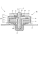
図1は光偏向器1の概略断面図である。光偏向器1は、多面鏡10とそれを回転される駆動モータ部を備える。駆動モータ部は、回転する部分としてのロータ16、光学箱118(図14参照)に固定され、回転しない部分である、ステータ20、固定軸(軸部材)12、及び、回路基板17を備える。
<Optical deflector>
FIG. 1 is a schematic sectional view of the optical deflector 1. The optical deflector 1 includes a polygon mirror 10 and a drive motor unit that rotates the polygon mirror 10. The drive motor unit includes a rotor 16 as a rotating part, a stator 20, a fixed shaft (shaft member) 12, and a circuit board 17 that are fixed to the optical box 118 (see FIG. 14) and are not rotated.

ロータ16は軸受(軸受部材)13、ロータフレーム14を備え、軸受13はロータフレーム14とカシメ等で一体的に結合(固定)されている。軸受13はフランジ部21を備え、軸受13に固定された不図示のバネによって多面鏡(ポリゴンミラー)10がフランジ部21に突き当てられることにより、多面鏡10を軸受13のフランジ部21で位置決め支持している。また、ロータフレーム14はロータマグネット(永久磁石)15が固定されている。このような構成により、多面鏡10、軸受13、ロータフレーム14およびロータマグネット15が一体的に回転する。   The rotor 16 includes a bearing (bearing member) 13 and a rotor frame 14, and the bearing 13 is integrally coupled (fixed) to the rotor frame 14 by caulking or the like. The bearing 13 includes a flange portion 21, and the polygon mirror 10 is abutted against the flange portion 21 by a spring (not shown) fixed to the bearing 13, thereby positioning the polygon mirror 10 with the flange portion 21 of the bearing 13. I support it. A rotor magnet (permanent magnet) 15 is fixed to the rotor frame 14. With such a configuration, the polygon mirror 10, the bearing 13, the rotor frame 14, and the rotor magnet 15 rotate integrally.

回路基板17は鉄製であり、ステータ20、及び、固定軸12を支持する。なお、回路基板17の素材は鉄製に限定されず、例えば、紙フェノールやガラスエポキシ等のプリント基板を金属プレート上に重ねて固定したようなものでも良い。ステータ20は導電性部材を積層することにより構成されたステータコア18、回路基板17の回路と電気的に接続されたコイル19、インシュレータ22を備える。インシュレータ22はステータコア18とコイル19を絶縁するための樹脂製の絶縁部材であり、ステータコア18とコイル19との間に設けられている。インシュレータ22は、ステータコア18の上下を挟み込む構成である。   The circuit board 17 is made of iron and supports the stator 20 and the fixed shaft 12. The material of the circuit board 17 is not limited to iron, and for example, a printed board such as paper phenol or glass epoxy may be stacked and fixed on a metal plate. The stator 20 includes a stator core 18 formed by laminating conductive members, a coil 19 electrically connected to the circuit of the circuit board 17, and an insulator 22. The insulator 22 is a resin insulating member for insulating the stator core 18 and the coil 19, and is provided between the stator core 18 and the coil 19. The insulator 22 is configured to sandwich the top and bottom of the stator core 18.

軸受13と固定軸12との間の隙間にはオイルが充填されており、軸受13の固定軸12と対向する面(軸受13の内周面)にはオイルによる動圧を発生させるための不図示の動圧発生溝が設けられている。回路基板17の回路によってコイル19に通電することにより、ロータ16及び多面鏡10が回転軸Z回りに回転する。   The gap between the bearing 13 and the fixed shaft 12 is filled with oil, and the surface of the bearing 13 that faces the fixed shaft 12 (the inner peripheral surface of the bearing 13) is not allowed to generate dynamic pressure due to oil. The illustrated dynamic pressure generating groove is provided. When the coil 19 is energized by the circuit of the circuit board 17, the rotor 16 and the polygonal mirror 10 rotate around the rotation axis Z.

次にロータ16の抜け止め構成について説明する。軸受13の下端部付近の外周部には円環状の溝24が設けられている。インシュレータ22の内周の一部には固定軸12に向かって(回転軸Zに直交する方向)に突出した突起部23が設けられている。突起部23はインシュレータ22の本体部に一体成型され、インシュレータ22の本体部から軸受13に向かって回転軸Z方向に直交する方向に突出している。突起部23はステータコア18よりも回転軸Zに近い位置に設けられている。また、インシュレータ22の、突起部23の径方向(回転軸Zに直交する方向)おける外側には突起部23の軸受13から離れる方向への変形を抑制するための突当面35が設けられている。   Next, the retaining structure of the rotor 16 will be described. An annular groove 24 is provided in the outer peripheral portion near the lower end portion of the bearing 13. A part of the inner periphery of the insulator 22 is provided with a protrusion 23 that protrudes toward the fixed shaft 12 (in a direction orthogonal to the rotation axis Z). The protrusion 23 is integrally formed with the main body of the insulator 22 and protrudes from the main body of the insulator 22 toward the bearing 13 in a direction perpendicular to the rotation axis Z direction. The protrusion 23 is provided at a position closer to the rotation axis Z than the stator core 18. Further, an abutting surface 35 is provided on the outer side of the insulator 22 in the radial direction of the protrusion 23 (a direction orthogonal to the rotation axis Z) to suppress deformation of the protrusion 23 in the direction away from the bearing 13. .

光偏向器の組立工程で前述のロータ16をステータ20へ組み付ける際、軸受13を軸12に挿入する。この際、軸受13は突起部23を回転軸Z方向下方に弾性的に変形させながら挿入され、弾性力で復帰した突起部23が多面鏡10側から見たときに溝24内に非接触状態で入り込んだ状態となる。   When the rotor 16 is assembled to the stator 20 in the optical deflector assembly process, the bearing 13 is inserted into the shaft 12. At this time, the bearing 13 is inserted while elastically deforming the protrusion 23 downward in the rotation axis Z direction, and the protrusion 23 restored by the elastic force is not in contact with the groove 24 when viewed from the polygon mirror 10 side. It will be in the state that entered.

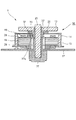
図2は、光偏向器1の突起部23付近の拡大断面図であり、ロータ16がステータ20から回転軸Z方向に関して離れる方向(抜け方向)に移動した時の突起部23の状態を示す。このような状態は、輸送時等に光偏向器1に振動や衝撃などが加わると発生する場合がある。   FIG. 2 is an enlarged cross-sectional view of the vicinity of the protrusion 23 of the optical deflector 1 and shows the state of the protrusion 23 when the rotor 16 moves away from the stator 20 in the direction away from the rotation axis Z (the removal direction). Such a state may occur when vibration or impact is applied to the optical deflector 1 during transportation or the like.

ロータ16がステータ20から回転軸Z方向に関して離れる方向(抜け方向)に所定距離移動すると、溝24の面24aが突起部23に当接し、突起部23を押圧する。しかし、突起部23が突当面35に突き当たることにより、突起部23の変形が抑制され、溝24の面24aが突起部23を押しのけてロータ16がステータ20から抜けることが規制される。このように、規制部(抜け止め部)としての突起部23が被規制部としての溝24の面24aの移動を規制することにより、回転軸Z方向に関してロータ16がステータ20から離れることを規制する。このような構成により、ロータ16をステータ20に組み付ける時よりも、ロータ16をステータ20から抜く時の方が、突起部23が変形しにくくなっている。つまり、ロータ16が突起部23を通過する際にロータ16が突起部23から受ける反力は、ロータ16をステータ20から抜く時の方がロータ16をステータ20に組み付ける時よりも大きい。   When the rotor 16 moves a predetermined distance in the direction away from the stator 20 with respect to the rotation axis Z direction (withdrawal direction), the surface 24a of the groove 24 comes into contact with the protrusion 23 and presses the protrusion 23. However, when the protrusion 23 abuts against the abutting surface 35, deformation of the protrusion 23 is suppressed, and the surface 24 a of the groove 24 pushes the protrusion 23 and the rotor 16 is prevented from coming out of the stator 20. As described above, the protrusion 23 as the restricting portion (retaining portion) restricts the movement of the surface 24a of the groove 24 as the restricted portion, thereby restricting the rotor 16 from being separated from the stator 20 in the rotation axis Z direction. To do. With such a configuration, the protrusion 23 is less likely to be deformed when the rotor 16 is removed from the stator 20 than when the rotor 16 is assembled to the stator 20. That is, the reaction force that the rotor 16 receives from the protrusion 23 when the rotor 16 passes through the protrusion 23 is greater when the rotor 16 is removed from the stator 20 than when the rotor 16 is assembled to the stator 20.

また、本実施形態の動圧発生溝は、回転軸Z方向に関して溝24と重なる部分には設けられておらず、回転軸Z方向に関して溝24と重ならない領域Aの部分に設けられている。このように、回転軸Z方向に関して溝24と重なる部分に動圧発生溝を設けないことにより、軸受13を軸12に挿入する時に、突起部23からの反力によって軸受13が変形しても動圧発生溝を傷つける虞を低減することができる。   Further, the dynamic pressure generating groove of the present embodiment is not provided in a portion that overlaps the groove 24 in the rotation axis Z direction, and is provided in a portion of the region A that does not overlap the groove 24 in the rotation axis Z direction. Thus, by not providing the dynamic pressure generating groove in the portion overlapping the groove 24 in the rotation axis Z direction, even when the bearing 13 is deformed by the reaction force from the projection 23 when the bearing 13 is inserted into the shaft 12. The possibility of damaging the dynamic pressure generating groove can be reduced.

なお、動圧発生溝は軸受13の内周面ではなく固定軸12の外周面に設けられていてもよく、この場合も領域Aの部分に設けることが好ましい。   The dynamic pressure generating groove may be provided not on the inner peripheral surface of the bearing 13 but on the outer peripheral surface of the fixed shaft 12. In this case, it is preferable to provide the dynamic pressure generating groove in the region A.

また、インシュレータ22に一体的に規制部を成型してさえいれば、被規制部の位置はどこでもよい。但し、本実施形態のように、周方向に沿って設けられる被規制部である溝24の面24aをステータコア18よりも回転軸Zに近くに設けることで、被規制部の大型化を抑制してロータ16の慣性モーメントを小さくできる。このため、多面鏡10を所定の回転速度まで加速させるのに必要な時間を短縮することができる。   Further, as long as the restriction portion is molded integrally with the insulator 22, the position of the restricted portion may be anywhere. However, as in this embodiment, the surface 24a of the groove 24, which is a regulated portion provided along the circumferential direction, is provided closer to the rotation axis Z than the stator core 18, thereby suppressing an increase in the size of the regulated portion. Thus, the moment of inertia of the rotor 16 can be reduced. For this reason, the time required to accelerate the polygon mirror 10 to a predetermined rotational speed can be shortened.

また、ロータ16がステータ20から抜けようとする力が比較的小さく、突当部23のインシュレータ22の本体部に対する弾性力で十分抜け止め機能を発揮できる場合、必ずしも突当面35は必要ではない。   In addition, the abutment surface 35 is not necessarily required when the force with which the rotor 16 tries to come out of the stator 20 is relatively small and the abutment portion 23 can sufficiently exhibit the function of preventing the removal by the elastic force of the abutment portion 23 against the main body portion of the insulator 22.

また、突起部23は、インシュレータ22の内周に複数個、又は、インシュレータ22の内周の全周に設けられていてもよい。   In addition, a plurality of protrusions 23 may be provided on the inner periphery of the insulator 22, or may be provided on the entire inner periphery of the insulator 22.

以上説明したように、本実施形態によれば、インシュレータ22に突起部23を一体的に成型することにより、突起部23の取り付け工程の削減や、部品点数を削減することができる。   As described above, according to the present embodiment, by forming the protrusion 23 integrally with the insulator 22, it is possible to reduce the attaching process of the protrusion 23 and the number of parts.

[第2実施形態]
次に第2実施形態について説明する。図3は第2実施形態の光偏向器1の概略断面図である。第1実施形態と重複する部分については同一の符号を付して説明を省略する。
[Second Embodiment]
Next, a second embodiment will be described. FIG. 3 is a schematic sectional view of the optical deflector 1 of the second embodiment. The same parts as those in the first embodiment are denoted by the same reference numerals and the description thereof is omitted.

本実施形態が第1実施形態と異なる点は軸受構成である。つまり、第1実施形態では固定軸12に対し軸受13が回転する構成であったが、本実施形態では、回路基板に固定された軸受27に対し、軸25が回転する構成である。軸受27と軸25との間にはオイルが充填されている。   The difference between this embodiment and the first embodiment is the bearing configuration. That is, in the first embodiment, the bearing 13 rotates with respect to the fixed shaft 12, but in this embodiment, the shaft 25 rotates with respect to the bearing 27 fixed to the circuit board. Oil is filled between the bearing 27 and the shaft 25.

ロータ36は、回転軸(軸部材)25、多面鏡10を支持する座面が設けられた支持部材26、及び、ロータフレーム14を一体的に備える。また、軸受(軸受部材)27は回路基板17に対して垂直に一体的に結合されている。ステータ29は、ステータコア18、コイル19、及び、インシュレータ28を備える。インシュレータ28は突出部23の構成を除いて第1実施形態のインシュレータ22と同様である。   The rotor 36 integrally includes a rotation shaft (shaft member) 25, a support member 26 provided with a seating surface that supports the polygon mirror 10, and the rotor frame 14. Further, the bearing (bearing member) 27 is integrally coupled to the circuit board 17 vertically. The stator 29 includes a stator core 18, a coil 19, and an insulator 28. The insulator 28 is the same as the insulator 22 of the first embodiment except for the configuration of the protruding portion 23.

次にロータ36の抜け止め構成について説明する。回転軸25は、軸受27と対向する部分よりも上方(多面鏡10側)の部分で、且つ、支持部材26よりも下方(軸受27側)に円環状の溝29が設けられている。一方、インシュレータ28の上方の溝29と対向する位置には回転軸25に向かって回転軸Zの直交する方向に延びた突起部(規制部)30が設けられている。また、突起部30の径方向(回転軸Zの直交する方向)における外側には突起部30の変形を抑制する突当面37が設けられている。   Next, the retaining structure of the rotor 36 will be described. The rotary shaft 25 is provided with an annular groove 29 above the portion facing the bearing 27 (on the polygon mirror 10 side) and below the support member 26 (on the bearing 27 side). On the other hand, at a position facing the groove 29 above the insulator 28, a protruding portion (regulating portion) 30 extending in the direction orthogonal to the rotation axis Z toward the rotation shaft 25 is provided. Further, an abutting surface 37 that suppresses deformation of the protrusion 30 is provided on the outer side in the radial direction of the protrusion 30 (the direction orthogonal to the rotation axis Z).

光偏向器1の組立工程では、回転軸25を軸受27に挿入する際、回転軸25は突起部30を径方向(回転軸Zの直交する方向)に弾性変形させながら挿入し、最終的に弾性力で復帰した突起部30が溝29内に非接触で入り込む。   In the assembly process of the optical deflector 1, when the rotary shaft 25 is inserted into the bearing 27, the rotary shaft 25 is inserted while elastically deforming the protrusion 30 in the radial direction (direction orthogonal to the rotary axis Z), and finally The protrusion 30 restored by the elastic force enters the groove 29 in a non-contact manner.

ロータ36が回転軸Z方向に移動し軸受27から抜けようとした際は、突起部30が被規制部としての溝29の面29aに当接する。そして突起部30が突当面35に突き当たることにより変形が抑制され、面29aの移動を規制することでロータ36が回転軸Z方向に関してステータ29から離れる(抜ける)ことを規制する。   When the rotor 36 moves in the direction of the rotation axis Z and tries to come out of the bearing 27, the protrusion 30 comes into contact with the surface 29a of the groove 29 as the restricted portion. Then, the deformation is suppressed by the protrusion 30 abutting against the abutting surface 35, and the movement of the surface 29a is restricted so that the rotor 36 is separated from (removed from) the stator 29 in the rotation axis Z direction.

なお、第1実施形態と同様に、突起部30は複数設けられるか、インシュレータ28の内径全周に設けられていてもよい。   As in the first embodiment, a plurality of protrusions 30 may be provided, or provided on the entire inner circumference of the insulator 28.

このように、ロータとステータのうちの一方が軸受を備え、他方が軸を備えていればよく、本実施形態のように、ロータが軸、ステータが軸受をそれぞれ備えていても、第1実施形態と同様の効果を得ることができる。   As described above, one of the rotor and the stator only needs to have a bearing and the other has a shaft. Even if the rotor has a shaft and the stator has a bearing as in this embodiment, the first embodiment The same effect as the form can be obtained.

<変形例>
図4は第2実施形態の変形例の光偏向器の概略断面図である。この図に示すように、回転軸25に溝29を設けるのではなく、支持部材26に円環状の溝32を設けてもよい。この構成の場合、ロータ36が回転軸Z方向に移動し軸受27から抜けようとした際は、突起部30が被規制部としての溝32の面32aに当接することで、ロータ36が回転軸Z方向に関してステータ29から離れる(抜ける)ことを規制する。このような構成によっても図3に示した構成と同様の効果を得ることができる。また、このような構成であれば、光偏向器1の組み立て時にロータ36を軸受27に挿入する際、突起部30が回転軸25に当接することを防ぐことができる。
<Modification>
FIG. 4 is a schematic sectional view of an optical deflector according to a modification of the second embodiment. As shown in this figure, instead of providing the groove 29 on the rotating shaft 25, an annular groove 32 may be provided on the support member 26. In the case of this configuration, when the rotor 36 moves in the direction of the rotation axis Z and tries to come out of the bearing 27, the protrusions 30 come into contact with the surface 32a of the groove 32 as the restricted portion, so that the rotor 36 is rotated. The separation from the stator 29 in the Z direction is restricted. Even with such a configuration, the same effect as the configuration shown in FIG. 3 can be obtained. Further, with such a configuration, it is possible to prevent the protrusion 30 from coming into contact with the rotating shaft 25 when the rotor 36 is inserted into the bearing 27 when the optical deflector 1 is assembled.

[第3実施形態]
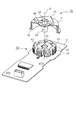
次に第3実施形態について説明する。図5は第3実施形態における光偏向器1のステータ部の斜視図である。図6は光偏向器を組み立てる様子を示す斜視図であり、説明のためロータフレーム14及び多面鏡10の一部を省略している。図7は光偏向器1の概略断面図である。なお、第1実施形態と重複する部分については同一の符号を付して説明を省略する。本実施形態は抜け止め構成が第1実施形態と異なる。
[Third Embodiment]
Next, a third embodiment will be described. FIG. 5 is a perspective view of the stator portion of the optical deflector 1 in the third embodiment. FIG. 6 is a perspective view showing a state in which the optical deflector is assembled, and a part of the rotor frame 14 and the polygon mirror 10 is omitted for explanation. FIG. 7 is a schematic sectional view of the optical deflector 1. In addition, about the part which overlaps with 1st Embodiment, the same code | symbol is attached | subjected and description is abbreviate | omitted. This embodiment is different from the first embodiment in the retaining structure.

まず、ステータ50の構成について図5を用いて説明する。回路基板17には固定軸12、ステータコア(積層コア)18、コイル19、インシュレータ51を固定して構成されたステータ50が固定されている。インシュレータ51の内周部にはインシュレータ51の本体部と一体的に成型された係止部(規制部)57が設けられている。係止部57は周方向に関して一部分に切り欠き部であるキー溝52が設けられており、インシュレータ51の開口は鍵穴状になっている。係止部57のキー溝52を除く円形の内径はステータコア18の内径よりも一回り小さく、キー溝52の最外部の内径はステータコア18の内径とほぼ同じである。   First, the configuration of the stator 50 will be described with reference to FIG. A stator 50 is fixed to the circuit board 17 by fixing the fixed shaft 12, the stator core (laminated core) 18, the coil 19, and the insulator 51. A locking portion (regulating portion) 57 formed integrally with the main body portion of the insulator 51 is provided on the inner peripheral portion of the insulator 51. The locking portion 57 is provided with a key groove 52 which is a notch portion in a part in the circumferential direction, and the opening of the insulator 51 has a keyhole shape. The circular inner diameter of the locking portion 57 excluding the key groove 52 is slightly smaller than the inner diameter of the stator core 18, and the outermost inner diameter of the key groove 52 is substantially the same as the inner diameter of the stator core 18.

次に、ロータ53の構成と、ロータ53のステータ50への組付けについて説明する。図6はロータ53をステータ50に組付けるときの様子を示す。ロータ53は、多面鏡10、多面鏡10を支持する座面56を備えた軸受(軸受部材)54、ロータマグネット15を備えたロータフレーム14とで構成される。これらはカシメ等により締結され、一体的に回転する。軸受54の外周面には突出部55が設けられている。突出部55は軸受54から回転軸Z方向に直交する方向でインシュレータ51に向かって外側に突出している。突出部55は、予め鍛造などにより軸受54に一体的に成型されている
このとき、軸受54の突出部55を除いた外径は係止部57の内径よりも小さいが、軸受54の回転中心を中心とした突出部55の最外部は係止部57の内径よりも大きく、且つ、ステータコア18の内径よりも小さい。また、突出部55の周方向の幅よりもキー溝52の周方向の幅が大きい。
Next, the configuration of the rotor 53 and the assembly of the rotor 53 to the stator 50 will be described. FIG. 6 shows a state when the rotor 53 is assembled to the stator 50. The rotor 53 includes a polygon mirror 10, a bearing (bearing member) 54 having a seat surface 56 that supports the polygon mirror 10, and a rotor frame 14 having a rotor magnet 15. These are fastened by caulking or the like and rotate integrally. A protrusion 55 is provided on the outer peripheral surface of the bearing 54. The protruding portion 55 protrudes outward from the bearing 54 toward the insulator 51 in a direction orthogonal to the rotation axis Z direction. The protrusion 55 is integrally molded with the bearing 54 in advance by forging or the like. At this time, the outer diameter of the bearing 54 excluding the protrusion 55 is smaller than the inner diameter of the locking part 57. The outermost part of the projecting portion 55 centered at the center is larger than the inner diameter of the locking portion 57 and smaller than the inner diameter of the stator core 18. Further, the circumferential width of the key groove 52 is larger than the circumferential width of the protruding portion 55.

このため、ロータ53をステータ50に組付ける際には、突出部55とキー溝52の回転軸Z回りの回転位相(以降は「位相」とする)を一致させた状態で軸受54をインシュレータ51に挿入する。これにより、突出部55はキー溝52内を通過することができる。つまり、軸受54の外形はインシュレータ51と非接触の状態で、軸受54および固定軸12の径方向に大きな外力を受けることなく、軸受54がインシュレータ51に挿入され、固定軸12が軸受54に挿入される。このように、突出部55とキー溝52との移動が一致している時にのみ、ロータ53をステータ50に対して回転軸Z方向に移動させた際に、突出部55がキー溝52を超えて移動可能となっている。   For this reason, when the rotor 53 is assembled to the stator 50, the bearing 54 is placed in the insulator 51 in a state where the rotation phase (hereinafter referred to as “phase”) of the protrusion 55 and the key groove 52 around the rotation axis Z is matched. Insert into. As a result, the protrusion 55 can pass through the keyway 52. That is, the outer shape of the bearing 54 is not in contact with the insulator 51, and the bearing 54 is inserted into the insulator 51 without receiving a large external force in the radial direction of the bearing 54 and the fixed shaft 12, and the fixed shaft 12 is inserted into the bearing 54. Is done. Thus, only when the movement of the protrusion 55 and the key groove 52 coincides, the protrusion 55 exceeds the key groove 52 when the rotor 53 is moved in the direction of the rotation axis Z with respect to the stator 50. Can be moved.

次に光偏向器組立後の状態について説明する。図7に示すように、軸受54がインシュレータ51に挿入が完了した状態で、突出部55を含む軸受54はインシュレータ51およびステータコア18とは非接触状態が保たれる。この状態では、突出部55とキー溝52の位相が完全に一致しない限り、固定軸12の軸方向から見たときに突出部55は係止部57と重なっている。このため、ロータ53を引き抜く力が働いたとしても突出部55が係止部57に突き当たることにより、ロータ53が回転軸Z方向にステータ50から離れることが規制される。   Next, a state after the optical deflector is assembled will be described. As shown in FIG. 7, in a state where the bearing 54 is completely inserted into the insulator 51, the bearing 54 including the protruding portion 55 is kept out of contact with the insulator 51 and the stator core 18. In this state, the protrusion 55 overlaps the locking part 57 when viewed from the axial direction of the fixed shaft 12 as long as the phases of the protrusion 55 and the keyway 52 do not completely match. For this reason, even if the force which pulls out the rotor 53 acts, when the protrusion part 55 hits the latching | locking part 57, it is controlled that the rotor 53 leaves | separates from the stator 50 in the rotating shaft Z direction.

また、永久磁石(ロータマグネット15)を用いたモータでは積層コア18の極間に隙間が存在することで、非励磁状態(コイル19が非通電状態)でロータ53を動かした際に、ロータ53は磁気的吸引力(コギングトルク)を受ける。このコギングトルクのかかる方向や大小は、ロータの回転角度に依存しており、ロータマグネット15の磁極とステータコア18の位置関係によってはコギングトルクが発生する。このため、ロータ53はコギングトルクが発生する位置には停止せず、コギングトルクの発生しない位置で停止する。そこで本実施形態では、コギングトルクの作用によりロータ53が停止する位置では、突出部55とキー溝52の位相が一致しないように、キー溝52の位相を決めている。つまり、コギングトルクの作用によりロータ53が停止するロータ53の位置とキー溝52と突出部55の位相が一致するロータ53の位置とが異なるようにしている。   Further, in a motor using a permanent magnet (rotor magnet 15), there is a gap between the poles of the laminated core 18, so that the rotor 53 is moved when the rotor 53 is moved in a non-excited state (the coil 19 is in a non-energized state). Receives magnetic attraction (cogging torque). The direction and magnitude of the cogging torque depends on the rotation angle of the rotor, and the cogging torque is generated depending on the positional relationship between the magnetic poles of the rotor magnet 15 and the stator core 18. For this reason, the rotor 53 does not stop at a position where the cogging torque is generated, but stops at a position where the cogging torque is not generated. Therefore, in the present embodiment, the phase of the key groove 52 is determined so that the phases of the protrusion 55 and the key groove 52 do not match at the position where the rotor 53 stops due to the action of cogging torque. In other words, the position of the rotor 53 where the rotor 53 stops due to the action of the cogging torque is different from the position of the rotor 53 where the phases of the keyway 52 and the protruding portion 55 coincide.

また、本実施例では突出部55を軸受に一箇所設けた場合について説明したが、複数の突出部55を軸受54の周方向に等間隔に設け、それに対応する複数のキー溝52を複数の突出部55に対応する位置に設けても良い。これにより、ロータ53の初期バランスを良化することができる。   Moreover, although the present Example demonstrated the case where the protrusion part 55 was provided in one place in the bearing, the several protrusion part 55 was provided in the circumferential direction of the bearing 54 at equal intervals, and the several key groove 52 corresponding to it is several. You may provide in the position corresponding to the protrusion part 55. FIG. Thereby, the initial balance of the rotor 53 can be improved.

このように、本実施形態によれば、第1実施形態と同様の効果を得ることができる。また、本実施形態では、ロータ53を組み付ける際に突出部55がキー溝52を通過させることにより、組み付け時に突出部55や係止部57に力がかからないようにして、ロータ53やステータ50へのダメージを抑制することができる。   Thus, according to this embodiment, the same effect as that of the first embodiment can be obtained. Further, in the present embodiment, when the rotor 53 is assembled, the protrusion 55 passes through the key groove 52, so that no force is applied to the protrusion 55 and the locking portion 57 during the assembly, so that the rotor 53 and the stator 50 are applied. Damage can be suppressed.

<変形例>
図8は第3実施形態の変形例である光偏向器を組み立てる様子を示す斜視図であり、説明のためロータフレーム14及び多面鏡10の一部を省略している。図9は第3実施形態の変形例である光偏向器の概略断面図である。第3実施形態と異なる部分についてのみ説明し、重複する部分については同様の符号を付し説明は省略する。本変形例では第3実施形態と比較して、突出部と係止部とを設ける部材異なる。つまり、本変形例では突出部をステータコア18に設け、係止部を軸受(軸受部材)54に設けている。
<Modification>
FIG. 8 is a perspective view showing a state in which an optical deflector that is a modification of the third embodiment is assembled, and a part of the rotor frame 14 and the polygonal mirror 10 is omitted for explanation. FIG. 9 is a schematic cross-sectional view of an optical deflector that is a modification of the third embodiment. Only portions different from the third embodiment will be described, and overlapping portions will be denoted by the same reference numerals and description thereof will be omitted. This modification differs from the third embodiment in the members that provide the protrusions and the locking portions. That is, in this modification, the protruding portion is provided on the stator core 18 and the locking portion is provided on the bearing (bearing member) 54.

具体的には、ロータ53の軸受54の外周には円環状の溝73が設けられており、溝73の面73aが係止部として機能する。また、軸受54にはキー溝74が設けられ、このキー溝74により面73aの一部を切り欠かいている。一方、ステータ75には、積層コアであるステータコア18の一部に、ステータコア18の本体部と一体的に成型された、内径側に(軸受54に向かって)突出した突出部(規制部)78が設けられている。ロータ53をステータ74に組み付ける際には、キー溝74と突出部78の位相を合わせた状態で挿入することにより、キー溝74内を突出部78が通過し、溝73内に突出部78が非接触で入り込む。   Specifically, an annular groove 73 is provided on the outer periphery of the bearing 54 of the rotor 53, and the surface 73a of the groove 73 functions as a locking portion. The bearing 54 is provided with a key groove 74, and a part of the surface 73 a is notched by the key groove 74. On the other hand, the stator 75 is formed integrally with a main body portion of the stator core 18 in a part of the stator core 18 that is a laminated core, and protrudes toward the inner diameter side (toward the bearing 54) (regulating portion) 78. Is provided. When the rotor 53 is assembled to the stator 74, the protrusions 78 pass through the key grooves 74 by inserting the key grooves 74 and the protrusions 78 in phase, and the protrusions 78 are inserted into the grooves 73. Enter without contact.

次に、ロータ70がステータ74に組付けられた状態について図9を用いて説明する。図9(a)はキー溝74と突出部78の位相を合わせた状態の概略断面図である。突出部78は回転軸Z方向において、溝73と同じ高さに設けられており、非接触状態で溝73に突出部78が入り込んでいる。この状態では、突出部78とキー溝74の位相が一致しているため、ロータ70はステータ75に対し挿抜自由である。   Next, a state where the rotor 70 is assembled to the stator 74 will be described with reference to FIG. FIG. 9A is a schematic cross-sectional view showing a state in which the phases of the key groove 74 and the protrusion 78 are matched. The protrusion 78 is provided at the same height as the groove 73 in the direction of the rotation axis Z, and the protrusion 78 enters the groove 73 in a non-contact state. In this state, since the phases of the projecting portion 78 and the key groove 74 coincide with each other, the rotor 70 can be freely inserted into and removed from the stator 75.

図9(b)は図9(a)からロータ70を回転軸Z回りに90°回転させた状態の概略断面図である。キー溝74は一部に設けられているため、突出部78と位相が一致していない。このため、回転軸Z方向から見たときに突出部78の先端は軸受54に溝73を設けたことにより形成された係止部としての面73aと重なっている。これにより、回転軸Z方向に関して、ロータ53をステータ75から離す方向(上方向)に移動させると、面73aが突出部78に当接し、それ以上ロータ53とステータ75とが離れることが規制される。このため、ロータ53がステータ75から抜けることを防ぐことができる。   FIG. 9B is a schematic cross-sectional view of the state in which the rotor 70 is rotated about the rotation axis Z by 90 ° from FIG. 9A. Since the key groove 74 is provided in part, the phase does not coincide with the protrusion 78. For this reason, when viewed from the direction of the rotation axis Z, the tip of the projecting portion 78 overlaps with a surface 73 a as a locking portion formed by providing the groove 54 in the bearing 54. As a result, when the rotor 53 is moved in the direction away from the stator 75 (upward) with respect to the rotation axis Z direction, the surface 73a abuts against the protrusion 78, and further separation of the rotor 53 and the stator 75 is restricted. The For this reason, it is possible to prevent the rotor 53 from coming off the stator 75.

なお、この変形例では軸受54に環状の溝73を設けることにより係止部となる面73aを設けたが、軸受54の外周部にフランジを設け、そのフランジの面を係止部としてもよい。また、突出部78はインシュレータ51本体部に一体的に成型して設けても良い。また、コギングトルクの作用によりロータ53が停止するロータ53の位置と、キー溝74と突出部78の位相が一致するロータ53の位置とが異なるようにしてもよい。また、複数のキー溝74を周方向に等間隔に設け、それに対応する複数の突出部78を複数のキー溝74に対応する位置に設けても良い。これにより、ロータ53の初期バランスを良化することができる。   In this modification, the bearing 54 is provided with the annular groove 73 to provide the surface 73a to be the locking portion. However, a flange may be provided on the outer periphery of the bearing 54, and the surface of the flange may be used as the locking portion. . Further, the projecting portion 78 may be integrally molded with the main body portion of the insulator 51. Further, the position of the rotor 53 where the rotor 53 stops due to the action of the cogging torque may be different from the position of the rotor 53 where the phases of the key groove 74 and the protruding portion 78 coincide. Further, a plurality of key grooves 74 may be provided at equal intervals in the circumferential direction, and a plurality of protrusions 78 corresponding thereto may be provided at positions corresponding to the plurality of key grooves 74. Thereby, the initial balance of the rotor 53 can be improved.

このような変形例でも第3実施形態と同様の効果を得ることができる。つまり、ロータとステータの一方に突出部を設け、他方に一部がキー溝によって切り欠かれた係止部を設けていれば上述した第3実施形態の効果を得ることができる。   Even in such a modification, the same effect as that of the third embodiment can be obtained. That is, the effect of the third embodiment described above can be obtained if a protrusion is provided on one of the rotor and the stator and a locking part partially cut off by the keyway is provided on the other.

[第4実施形態]
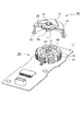
図10は第4実施形態の光偏向器のステータ部の斜視図である。図11は第4実施形態の光偏向器を組み立てる様子を示す斜視図である。なお、説明のためロータフレーム14及び多面鏡10の一部を省略している。図12は第4実施形態の光偏向器の概略断面図である。なお、本実施形態では第2実施形態と重複する部分については同一の符号を付して説明を省略する。
[Fourth Embodiment]
FIG. 10 is a perspective view of the stator portion of the optical deflector of the fourth embodiment. FIG. 11 is a perspective view showing a state where the optical deflector of the fourth embodiment is assembled. For the sake of explanation, a part of the rotor frame 14 and the polygon mirror 10 is omitted. FIG. 12 is a schematic cross-sectional view of the optical deflector of the fourth embodiment. In addition, in this embodiment, about the part which overlaps with 2nd Embodiment, the same code | symbol is attached | subjected and description is abbreviate | omitted.

本実施形態が第3実施形態と異なるのは、ロータ36が回転軸(軸部材)25を備え、ステータ29が固定の軸受(軸受部材)27を備える点である。従って、突出部は回転軸25に設けられている。   This embodiment is different from the third embodiment in that the rotor 36 includes a rotating shaft (shaft member) 25 and the stator 29 includes a fixed bearing (bearing member) 27. Therefore, the protrusion is provided on the rotating shaft 25.

まず、ステータ29の構成について図10を用いて説明する。インシュレータ28の内周部にはインシュレータ28の本体部に対して一体的に形成された係止部(規制部)66が設けられており、キー溝61によって係止部66の一部が切り欠かれている。キー溝61を除く係止部66の内径はステータコア18の内径よりも一回り小さい。ロータ36の面鏡10を支持する支持部材26の外周部には、突出部64が予め鍛造などにより一体的に成型されている。突出部64はインシュレータ28に向かって突出した形状である。   First, the configuration of the stator 29 will be described with reference to FIG. The inner peripheral portion of the insulator 28 is provided with a locking portion (regulating portion) 66 formed integrally with the main body portion of the insulator 28, and a part of the locking portion 66 is notched by the key groove 61. It is. The inner diameter of the locking portion 66 excluding the key groove 61 is slightly smaller than the inner diameter of the stator core 18. On the outer peripheral portion of the support member 26 that supports the face mirror 10 of the rotor 36, a protruding portion 64 is integrally formed in advance by forging or the like. The protruding portion 64 has a shape protruding toward the insulator 28.

ロータ36をステータ29に組み付ける際には、図11に示すように、突出部64とインシュレータ28に設けられたキー溝61の位相を合わせた状態で挿入することにより、突出部64がキー溝61を通過する。なお、周方向に関して、キー溝61の幅の方が突出部64の幅よりも大きく、径方向に関して、キー溝の内径の最大径の方が突出部64の最大径よりも大きい。   When the rotor 36 is assembled to the stator 29, as shown in FIG. 11, the protrusion 64 is inserted into the key groove 61 by inserting the protrusion 64 and the key groove 61 provided in the insulator 28 in phase with each other. Pass through. Note that the width of the key groove 61 is larger than the width of the protruding portion 64 in the circumferential direction, and the maximum inner diameter of the key groove is larger than the maximum diameter of the protruding portion 64 in the radial direction.

このため、突出部64とキー溝61の位相を合せながら挿入することで、回転軸25はインシュレータ28と非接触の状態、つまりは回転軸25の径方向に大きな外力を受けることなく、軸受27へ挿入される。   For this reason, by inserting the protrusion 64 and the keyway 61 in phase with each other, the rotary shaft 25 is not in contact with the insulator 28, that is, without receiving a large external force in the radial direction of the rotary shaft 25. Is inserted.

次に組立後の状態について説明する。図12に示すように、組立後、突出部64を含む支持部材26はインシュレータ29やステータコア18とは非接触状態である。突出部64とキー溝61の位相が完全に一致しない限り、回転軸Z方向に関してロータ36をステータ29から離れるように移動させると、突出部64が係止部66に当接することにより、ロータ36をステータ29から離れることが規制される。   Next, the state after assembly will be described. As shown in FIG. 12, after the assembly, the support member 26 including the protruding portion 64 is not in contact with the insulator 29 and the stator core 18. Unless the phases of the protrusions 64 and the key grooves 61 completely match, when the rotor 36 is moved away from the stator 29 in the direction of the rotation axis Z, the protrusions 64 abut against the locking portions 66, thereby causing the rotor 36 to move. From the stator 29 is restricted.

なお、第3実施形態と同様に、コギングトルクの作用によりロータ36が停止するロータ36の位置と、キー溝61と突出部64の位相が一致するロータ36の位置とが異なるようにしてもよい。また、複数の突出部64を周方向に等間隔に設け、それに対応する複数のキー溝61を複数の突出部64に対応する位置に設けても良い。これにより、ロータ36の初期バランスを良化することができる。また、突出部とステータ29に係止部をロータ36に設けてもよい。   As in the third embodiment, the position of the rotor 36 where the rotor 36 stops due to the action of the cogging torque may be different from the position of the rotor 36 where the phases of the key groove 61 and the protruding portion 64 match. . Further, a plurality of protrusions 64 may be provided at equal intervals in the circumferential direction, and a plurality of key grooves 61 corresponding thereto may be provided at positions corresponding to the plurality of protrusions 64. Thereby, the initial balance of the rotor 36 can be improved. Further, a locking portion may be provided on the rotor 36 on the protrusion and the stator 29.

このような構成により、本実施形態では第3実施形態と同様の効果を得ることができる。   With this configuration, the present embodiment can achieve the same effects as those of the third embodiment.

1 光偏向器
16、36、53 ロータ
20、29、50 ステータ
19 コイル
10 多面鏡
22、28 インシュレータ
23、30 突起部
52、61、74 キー溝
55、64、78 突出部
57、66、73 係止部
100 光学走査装置
101 画像形成装置
1 Optical deflector 16, 36, 53 Rotor 20, 29, 50 Stator 19 Coil 10 Polyhedral mirror 22, 28 Insulator 23, 30 Protrusion 52, 61, 74 Key groove 55, 64, 78 Protrusion 57, 66, 73 Stop 100 Optical scanning device 101 Image forming apparatus

Claims (13)

光を反射する多面鏡、及び、磁石を一体的に備えるロータと、
ステータコア、コイル、及び、前記ステータコアと前記コイルとを絶縁する絶縁部材を備えるステータと、
を有し、前記コイルに通電することで前記ロータを回転させる光偏向装置において、
前記絶縁部材には、前記ロータの回転軸方向に関して、前記ロータが前記ステータから離れることを規制する規制部が一体的に成型されていることを特徴とする光偏向装置。
A polygon mirror that reflects light, and a rotor that integrally includes a magnet;
A stator including a stator core, a coil, and an insulating member that insulates the stator core and the coil;
In the optical deflection device that rotates the rotor by energizing the coil,
The light deflection apparatus according to claim 1, wherein the insulating member is integrally formed with a restricting portion that restricts the rotor from being separated from the stator with respect to a rotation axis direction of the rotor.
前記ロータは、前記ロータの回転軸方向に関して前記ロータが前記ステータから所定距離離れた際に、前記規制部に当接する被規制部を備えることを特徴とする請求項1に記載の光偏向装置。   The optical deflection apparatus according to claim 1, wherein the rotor includes a regulated portion that comes into contact with the regulating portion when the rotor is separated from the stator by a predetermined distance in the rotation axis direction of the rotor. 前記規制部は前記絶縁部材の本体部に対して弾性変形可能な部分であることを特徴とする請求項1又は2に記載に光偏向装置。   The light deflection apparatus according to claim 1, wherein the restricting portion is a portion that is elastically deformable with respect to a main body portion of the insulating member. 前記ロータと前記ステータのうち、一方は軸部材を備え、他方は前記軸部材が回転可能に嵌合した軸受部材を備えることを特徴とする請求項1乃至3のいずれか一項に記載の光偏向装置。   4. The light according to claim 1, wherein one of the rotor and the stator includes a shaft member, and the other includes a bearing member into which the shaft member is rotatably fitted. Deflection device. 前記軸部材又は前記軸受部材には動圧発生溝が形成されており、前記ロータの回転軸方向に関して、前記動圧発生溝は前記規制部及び前記被規制部に重ならない位置に設けられていることを特徴とする請求項4に記載の光偏向装置。   A dynamic pressure generating groove is formed in the shaft member or the bearing member, and the dynamic pressure generating groove is provided at a position that does not overlap the restricting portion and the restricted portion with respect to the rotation axis direction of the rotor. The optical deflection apparatus according to claim 4, wherein: 前記ロータは、前記軸部材と、前記軸部材に固定された前記多面鏡を支持する支持部材と、を備え、前記被規制部は前記支持部材に設けられていることを特徴とする請求項4に記載の光偏向装置。   The said rotor is provided with the said shaft member and the supporting member which supports the said polygon mirror fixed to the said shaft member, The said to-be-regulated part is provided in the said supporting member, The 4th characterized by the above-mentioned. The light deflection apparatus described in 1. 前記規制部は前記コイルよりも前記ロータの回転軸に近い位置に配置されていることを特徴とする請求項1乃至6のいずれか一項に記載の光偏向装置。   The optical deflecting device according to claim 1, wherein the restricting portion is disposed at a position closer to the rotation axis of the rotor than the coil. 光を反射する多面鏡、及び、磁石を一体的に備えるロータと、
ステータコア、及び、コイルを備えるステータと、
を有し、前記コイルに通電することで前記ロータを回転させる光偏向装置において、
前記ロータと前記ステータのうち、一方には他方に向かって前記ロータの回転軸に直交する方向に突出した突出部が設けられ、他方には前記突出部に係止することで前記回転軸方向に関して前記ロータが前記ステータから離れることを規制する係止部が設けられ、
前記係止部の前記回転軸を中心とした周方向に関して一部分に切り欠き部が設けられ、前記ロータが前記周方向に関して所定の位置にある時に、前記突出部に前記切り欠き部を通過させて、前記ロータを前記ステータに対して前記回転軸方向に移動可能であることを特徴とする光偏向装置。
A polygon mirror that reflects light, and a rotor that integrally includes a magnet;
A stator including a stator core and a coil;
In the optical deflection device that rotates the rotor by energizing the coil,
One of the rotor and the stator is provided with a protrusion that protrudes in the direction perpendicular to the rotation axis of the rotor toward the other, and the other is engaged with the protrusion so that the rotation axis direction is engaged. A locking portion for restricting the rotor from separating from the stator is provided,
A notch part is provided in a part in the circumferential direction around the rotation axis of the locking part, and when the rotor is in a predetermined position in the circumferential direction, the notch part is passed through the protruding part. The optical deflection apparatus characterized in that the rotor is movable in the direction of the rotation axis with respect to the stator.
前記ロータは複数の前記突出部を備え、前記複数の突出部は前記回転軸を中心とした周方向に関して等間隔に設けられていることを特徴とする請求項8に記載の光偏向装置。   The optical deflection apparatus according to claim 8, wherein the rotor includes a plurality of protrusions, and the plurality of protrusions are provided at equal intervals in a circumferential direction around the rotation axis. 前記ロータは複数の前記切り欠き部を備え、前記複数の切り欠き部前記回転軸を中心とした周方向に関して等間隔に設けられていることを特徴とする請求項8に記載の光偏向装置。 The optical deflection apparatus according to claim 8, wherein the rotor includes a plurality of the cutout portions, and the plurality of cutout portions are provided at equal intervals in a circumferential direction around the rotation axis. . 前記所定の位置は、前記コイルが非通電状態におけるコギングトルクの作用により前記ロータが停止する位置と異なることを特徴とする請求項8乃至10のいずれか一項に記載の光偏向装置。   11. The optical deflection apparatus according to claim 8, wherein the predetermined position is different from a position where the rotor stops due to an action of cogging torque when the coil is in a non-energized state. 請求項1乃至11のいずれか一項に記載の光偏向装置を備え、前記多面鏡により光を走査することを特徴とする光学走査装置。   An optical scanning device comprising the light deflecting device according to claim 1, wherein light is scanned by the polygon mirror. 請求項12に記載の光学走査装置と、感光体と、を有し、前記感光体を前記光学走査装置によって走査することに画像を形成する画像形成装置。   An image forming apparatus, comprising: the optical scanning device according to claim 12; and a photoconductor, and forming an image by scanning the photoconductor with the optical scanning device.
JP2013172648A 2013-08-22 2013-08-22 Optical deflection device Active JP6207301B2 (en)

Priority Applications (1)

Application Number Priority Date Filing Date Title
JP2013172648A JP6207301B2 (en) 2013-08-22 2013-08-22 Optical deflection device

Applications Claiming Priority (1)

Application Number Priority Date Filing Date Title
JP2013172648A JP6207301B2 (en) 2013-08-22 2013-08-22 Optical deflection device

Publications (2)

Publication Number Publication Date
JP2015041013A JP2015041013A (en) 2015-03-02
JP6207301B2 true JP6207301B2 (en) 2017-10-04

Family

ID=52695197

Family Applications (1)

Application Number Title Priority Date Filing Date
JP2013172648A Active JP6207301B2 (en) 2013-08-22 2013-08-22 Optical deflection device

Country Status (1)

Country Link
JP (1) JP6207301B2 (en)

Families Citing this family (1)

* Cited by examiner, † Cited by third party
Publication number Priority date Publication date Assignee Title
EP3811138A4 (en) * 2019-08-22 2021-04-28 SZ DJI Technology Co., Ltd. Motors for driving multi-element optical scanning devices, and associated systems and methods

Family Cites Families (7)

* Cited by examiner, † Cited by third party
Publication number Priority date Publication date Assignee Title
JP3029121B2 (en) * 1990-08-28 2000-04-04 キヤノン株式会社 Hydrodynamic bearing rotating device
JPH08121478A (en) * 1994-10-18 1996-05-14 Fuji Xerox Co Ltd Bearing device
JPH09126229A (en) * 1995-08-31 1997-05-13 Konica Corp Dynamic pressure bearing, light deflection device and recorder
JP3391954B2 (en) * 1995-10-04 2003-03-31 株式会社リコー High speed rotating body and dynamic pressure air bearing type polygon scanner having the rotating body
JPH1184302A (en) * 1997-09-05 1999-03-26 Canon Inc Deflection scanner
JP4582906B2 (en) * 2000-12-21 2010-11-17 日本電産コパル電子株式会社 Dynamic pressure bearing type optical deflector
JP2006194400A (en) * 2005-01-17 2006-07-27 Matsushita Electric Ind Co Ltd Spindle motor and rotating device

Also Published As

Publication number Publication date
JP2015041013A (en) 2015-03-02

Similar Documents

Publication Publication Date Title
US20070115527A1 (en) Light deflecting apparatus
EP3581372A2 (en) Polygonal mirror, deflector, optical scanning apparatus, image forming apparatus, and manufacturing method of the polygonal mirror
US7471433B2 (en) Optical scanning apparatus
JP6207301B2 (en) Optical deflection device
JP6949665B2 (en) Optical deflector, optical scanning device and image forming device
JP2010237432A (en) Optical scanner and image forming apparatus using the same
KR101493367B1 (en) Laser Scanning Unit And Image Forming Apparatus Having The Same
US8169677B2 (en) Scanner motor
US9715108B2 (en) Scanning optical apparatus
JP4474064B2 (en) Drive motor
US11703776B2 (en) Light deflector, light scanning apparatus and image forming apparatus
JP2017072777A (en) Scan optical device and image formation apparatus
JP6700746B2 (en) Scanning optics
JP2008040282A (en) Optical deflector, scanning optical apparatus and image forming apparatus
JP2017194618A (en) Optical deflector, optical scanner, and image formation apparatus
JP2015197600A (en) Optical deflector and scanning optical system
JP2001166246A (en) Optical deflecting device and writing optical device
JP5235521B2 (en) Optical deflection apparatus, optical scanning apparatus, and image forming apparatus
JP2012194393A (en) Optical scanning device
JP3459731B2 (en) Light deflection device
CN117741954A (en) Optical deflector, scanning optical device, and image forming apparatus
JP2019061013A (en) Scanning optical device and image forming apparatus
JPH1184302A (en) Deflection scanner
JP2004205786A (en) Scanning optical device
JPS6122322A (en) Laser beam scanning device

Legal Events

Date Code Title Description
A621 Written request for application examination

Free format text: JAPANESE INTERMEDIATE CODE: A621

Effective date: 20160804

A977 Report on retrieval

Free format text: JAPANESE INTERMEDIATE CODE: A971007

Effective date: 20170518

A131 Notification of reasons for refusal

Free format text: JAPANESE INTERMEDIATE CODE: A131

Effective date: 20170523

A521 Written amendment

Free format text: JAPANESE INTERMEDIATE CODE: A523

Effective date: 20170721

TRDD Decision of grant or rejection written
A01 Written decision to grant a patent or to grant a registration (utility model)

Free format text: JAPANESE INTERMEDIATE CODE: A01

Effective date: 20170808

A61 First payment of annual fees (during grant procedure)

Free format text: JAPANESE INTERMEDIATE CODE: A61

Effective date: 20170905

R151 Written notification of patent or utility model registration

Ref document number: 6207301

Country of ref document: JP

Free format text: JAPANESE INTERMEDIATE CODE: R151