JP6205756B2 - Synchronous measurement system - Google Patents
Synchronous measurement system Download PDFInfo
- Publication number
- JP6205756B2 JP6205756B2 JP2013045158A JP2013045158A JP6205756B2 JP 6205756 B2 JP6205756 B2 JP 6205756B2 JP 2013045158 A JP2013045158 A JP 2013045158A JP 2013045158 A JP2013045158 A JP 2013045158A JP 6205756 B2 JP6205756 B2 JP 6205756B2
- Authority
- JP
- Japan
- Prior art keywords
- sub
- controller
- controllers
- trigger signal
- main controller
- Prior art date
- Legal status (The legal status is an assumption and is not a legal conclusion. Google has not performed a legal analysis and makes no representation as to the accuracy of the status listed.)
- Active
Links
Images


Classifications
-
- H—ELECTRICITY
- H04—ELECTRIC COMMUNICATION TECHNIQUE
- H04L—TRANSMISSION OF DIGITAL INFORMATION, e.g. TELEGRAPHIC COMMUNICATION
- H04L67/00—Network arrangements or protocols for supporting network services or applications
- H04L67/01—Protocols
- H04L67/12—Protocols specially adapted for proprietary or special-purpose networking environments, e.g. medical networks, sensor networks, networks in vehicles or remote metering networks
-
- H—ELECTRICITY
- H04—ELECTRIC COMMUNICATION TECHNIQUE
- H04L—TRANSMISSION OF DIGITAL INFORMATION, e.g. TELEGRAPHIC COMMUNICATION
- H04L12/00—Data switching networks
- H04L12/28—Data switching networks characterised by path configuration, e.g. LAN [Local Area Networks] or WAN [Wide Area Networks]
- H04L12/46—Interconnection of networks
- H04L12/4604—LAN interconnection over a backbone network, e.g. Internet, Frame Relay
- H04L12/462—LAN interconnection over a bridge based backbone
Description
本発明は、同期計測システム等に関する。 The present invention relates to a synchronous measurement system and the like.
複数のセンサーユニットを被検出体に装着して、被検出体の動き、姿勢、歪等の各種情報を計測することがある。この場合、複数のセンサーユニットの各々から収集されるデータ間には、同期が取られている必要がある。 There are cases where a plurality of sensor units are mounted on a detection object, and various types of information such as movement, posture, and distortion of the detection object are measured. In this case, the data collected from each of the plurality of sensor units needs to be synchronized.
特許文献1では、例えば通信の同期検出のために、マスター通信回路と複数のスレーブ通信回路とが用意される。マスター通信回路は、複数のスレーブ通信回路の一つとの間で通信する際に、通信データに加えて、同期の開始と同期検出用のカウントデータとを、例えば0,1,2,…のように更新して伝送する。このカウントデータを受信することで、複数のスレーブ通信回路の各々は通信の同期タイミングが得られる。また、スレーブ通信回路が何らかの理由によりカウントデータを取り損なっても、次のカウントデータの更新により同期タイミングが得られるので、マスター通信回路がリトライする必要がない。
In
特許文献1の同期検出システムは集中型と称することができる。通信の同期は、マスター通信回路からのカウントデータの伝送により、専らマスター通信回路で集中的に管理されるからである。
The synchronization detection system of
集中型の場合、通信路が高度な通信が可能な通信路となるため、通信路での同期コマンド通信時間の不確定性により同期精度が低下するという問題がある。 In the case of the centralized type, since the communication path is a communication path capable of advanced communication, there is a problem that synchronization accuracy is lowered due to uncertainty of the synchronization command communication time in the communication path.
また、特許文献1はマスター通信回路とスレーブ通信回路との間の通信の同期を取るものであって、複数のセンサーユニットの同期を一斉にとるものではない。
Further,
本発明の幾つかの態様は、メインコントローラーの負担を軽減し、複数のサブコントローラーでの分散処理により複数のセンサーユニットの同期を一斉にとることができ、高精度な同期計測システムを提供することを目的とする。 Some aspects of the present invention provide a highly accurate synchronous measurement system that can reduce the burden on the main controller and can simultaneously synchronize a plurality of sensor units by distributed processing with a plurality of sub-controllers. With the goal.
(1)本発明の一態様は、
メインコントローラーと、
前記メインコントローラーに接続された複数のサブコントローラーと、
前記複数のサブコントローラーの各々に接続された複数のセンサーユニットと、
を有し、
前記複数のサブコントローラーは、サブコントローラーマスターと、前記サブコントローラーマスターに接続されたサブコントローラースレーブと、を含み、
前記メインコントローラーは、前記サブコントローラーマスターに開始コマンドを送出し、
前記サブコントローラーマスターは、前記開始コマンドの受信によりトリガ信号を発生させ、前記サブコントローラースレーブに前記トリガ信号を送出し、
前記複数のサブコントローラーの各々は、前記トリガ信号に基づいて同期コマンドを前記複数のセンサーユニットに送出する同期計測システムに関する。
(1) One aspect of the present invention is
The main controller,
A plurality of sub-controllers connected to the main controller;
A plurality of sensor units connected to each of the plurality of sub-controllers;
Have
The plurality of sub-controllers include a sub-controller master and a sub-controller slave connected to the sub-controller master,
The main controller sends a start command to the sub-controller master,
The sub controller master generates a trigger signal by receiving the start command, and sends the trigger signal to the sub controller slave.
Each of the plurality of sub-controllers relates to a synchronous measurement system that sends a synchronization command to the plurality of sensor units based on the trigger signal.
本発明の一態様では、メインコントローラーから開始コマンドを受信したサブコントローラーマスターがトリガ信号を発生し、サブコントローラースレーブに送信する。複数のサブコントローラー(サブコントローラーマスター及びサブコントローラースレーブ)の各々は、トリガ信号に基づいて、複数のセンサーユニットに同期コマンドを送信する。これにより、全サブコントローラーに接続されている全センサーユニットにて一斉に同期を取ることができる。しかも、メインコントローラーは開始コマンドを送出した後は関与せず、複数のサブコントローラーの各々で分散して同期検出することができる。 In one aspect of the present invention, the sub controller master that has received the start command from the main controller generates a trigger signal and transmits it to the sub controller slave. Each of the plurality of sub-controllers (sub-controller master and sub-controller slave) transmits a synchronization command to the plurality of sensor units based on the trigger signal. As a result, all sensor units connected to all the sub-controllers can be synchronized simultaneously. In addition, the main controller is not involved after sending the start command, and can be detected synchronously in each of the plurality of sub-controllers.
(2)本発明の一態様では、前記開始コマンドは、計測回数の情報を含み、前記サブコントローラーマスターは、前記開始コマンドの受信により、前記計測回数分だけ前記トリガ信号を繰り返し発生することができる。 (2) In one aspect of the present invention, the start command includes information on the number of times of measurement, and the sub controller master can repeatedly generate the trigger signal for the number of times of measurement upon reception of the start command. .
こうすると、複数のセンサーユニットの各々にて複数の計測データを連続して計測する場合でも、メインコントローラーは開始コマンドを1回だけ送信するだけ良く、メインコントローラーが同期検出に関与する時間を大幅に削減できる。なお、計測回数の情報は開始コマンドに続いて送信されても良い。 In this way, the main controller only needs to send a start command once, even when measuring multiple measurement data continuously in each of the multiple sensor units, greatly increasing the time that the main controller is involved in synchronization detection. Can be reduced. Note that the information on the number of times of measurement may be transmitted following the start command.
(3)本発明の一態様では、前記開始コマンドは、計測間隔の情報を含むことができる。これにより、計測回数分だけ繰り返される計測の間隔を、開始コマンドにより指定することができる。この場合も、計測回数や計測間隔の情報は開始コマンドに続いて送信されても良い。 (3) In one aspect of the present invention, the start command may include measurement interval information. Thereby, the measurement interval repeated by the number of times of measurement can be designated by the start command. Also in this case, information on the number of measurements and the measurement interval may be transmitted following the start command.
(4)本発明の一態様では、前記サブコントローラースレーブは複数設けられ、前記サブコントローラーマスターには、前記複数のサブコントローラースレーブが直列接続されても良い。こうすると、サブコントローラースレーブの数が増えても、サブコントローラーマスターと複数のサブコントローラースレーブとを直列接続すればよく、スター型接続と比較してケーブル敷設等が容易である。 (4) In one aspect of the present invention, a plurality of the sub controller slaves may be provided, and the plurality of sub controller slaves may be connected in series to the sub controller master. In this way, even if the number of sub-controller slaves increases, the sub-controller master and the plurality of sub-controller slaves may be connected in series, and cable laying and the like is easier compared to the star-type connection.
(5)本発明の一態様では、前記トリガ信号はデジタル信号とすることができる。こうすると、2値化されたデジタル信号のエッジで同期タイミングを判定することができる。このとき、デイジーチェーン接続の途中にあるサブコントローラースレーブに、デジタル信号を波形成形するバッファ等を設けて、同期精度を高めることができる。 (5) In one aspect of the present invention, the trigger signal may be a digital signal. In this way, the synchronization timing can be determined by the edge of the binarized digital signal. At this time, the sub controller slave in the middle of the daisy chain connection can be provided with a buffer for shaping the waveform of the digital signal to improve the synchronization accuracy.
(6)本発明の一態様では、前記トリガ信号は光信号とすることができる。それにより、サブコントローラーマスターから遠い距離を隔てて配置されたサブコントローラースレーブにも、あるいはセンサーユニットでのサンプリング周波数が高くても、同期上無視できる遅延時間でトリガ信号を送信することができる。 (6) In one aspect of the present invention, the trigger signal may be an optical signal. As a result, the trigger signal can be transmitted to a sub-controller slave arranged at a long distance from the sub-controller master or with a delay time negligible for synchronization even when the sampling frequency of the sensor unit is high.
(7)本発明の一態様では、前記メインコントローラーと前記複数のサブコントローラーとはLAN(Local Area Network)接続され、前記少なくとも一つのサブコントローラースレーブは、前記メインコントローラーから前記開始コマンドを受信して、前記トリガ信号の受付けを待機するスタンバイ状態に設定することができる。 (7) In one aspect of the present invention, the main controller and the plurality of sub-controllers are connected by a LAN (Local Area Network), and the at least one sub-controller slave receives the start command from the main controller. A standby state in which the trigger signal is received can be set.
メインコントローラーと複数のサブコントローラーとをLAN接続することで、複数のサブコントローラーに収集された計測データは、LANを介してメインコントローラーに送信して集中管理することができる。このLANを用いて、メインコントローラーから開始コマンドを受信したサブコントローラースレーブは、トリガ信号の受付けを待機するスタンバイ状態に設定することができる。 By connecting the main controller and the plurality of sub-controllers via LAN, the measurement data collected by the plurality of sub-controllers can be sent to the main controller via the LAN for centralized management. Using this LAN, the sub-controller slave that has received the start command from the main controller can be set to a standby state in which it waits for acceptance of the trigger signal.
(8)本発明の一態様では、複数のセンサーユニットの各々は、加速度センサーと角速度センサーと、を含むことができる。これにより、被検体(人体、移動体、不動産等)の複数個所での動き、姿勢、歪等の各種情報を同期して計測することができる。 (8) In one aspect of the present invention, each of the plurality of sensor units can include an acceleration sensor and an angular velocity sensor. Thereby, various information such as movements, postures, and distortions at a plurality of locations of the subject (human body, mobile body, real estate, etc.) can be measured in synchronization.
(9)本発明の一態様では、前記メインコントローラーに接続された表示部をさらに有し、計測前に実施される動作確認モードにて、前記複数のサブコントローラーの各々からのコマンドに応答して、前記複数のセンサーユニットからIDが送出され、応答の無いセンサーユニットのエラー情報が前記メインコントローラーにより前記表示部に表示しても良い。 (9) In one aspect of the present invention, the display device further includes a display unit connected to the main controller, and in response to a command from each of the plurality of sub-controllers in an operation check mode performed before measurement. The IDs may be sent from the plurality of sensor units, and error information of sensor units having no response may be displayed on the display unit by the main controller.
このように、同期計測する上で前提となるメインコントローラー、複数のサブコントローラー及び複数のセンサーユニットの接続状態は、メインコントローラーにより確認されて表示部に表示することができる。 Thus, the connection state of the main controller, the plurality of sub-controllers, and the plurality of sensor units, which are prerequisites for synchronous measurement, can be confirmed by the main controller and displayed on the display unit.
以下、本発明の好適な実施の形態について詳細に説明する。なお以下に説明する本実施形態は特許請求の範囲に記載された本発明の内容を不当に限定するものではなく、本実施形態で説明される構成の全てが本発明の解決手段として必須であるとは限らない。 Hereinafter, preferred embodiments of the present invention will be described in detail. The present embodiment described below does not unduly limit the contents of the present invention described in the claims, and all the configurations described in the present embodiment are indispensable as means for solving the present invention. Not necessarily.
1.同期計測システム
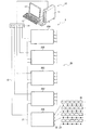
図1は、本実施形態に係る同期計測システム1を示している。図1において、同期計測システム1は、メインコントローラー10と、メインコントローラー10にLAN接続された複数のサブコントローラー20A〜20Eと、を有する。複数のサブコントローラー20A〜20Eの各々には、複数のセンサーユニット30が接続されている。
1. Synchronous Measurement System FIG. 1 shows a
メインコントローラー10は例えばパーソナルコンピューターであり、本体11と、表示部12と、キーボード13と、インサーネットハブ14とを有する。メインコントローラー10は、同期計測システム実行プログラムがインストールされて、5台のサブコントローラー20A〜20Eでの同期計測を制御する。
The
複数のサブコントローラー20A〜20Eは、メインコントローラー10のインサーネットハブ14にインサーネットケーブル15により接続されている。複数のサブコントローラー20A〜20Eの一台はサブコントローラーマスター20Aであり、他の4台はサブコントローラーマスター20Aに接続されたサブコントローラースレーブ20B〜20Eである。
The plurality of
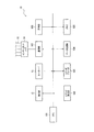
本実施形態では、複数のサブコントローラー20A〜20Eは、例えば光通信ケーブル21によりデイジーチェーン接続されている。つまり、サブコントローラーマスター20Aにサブコントローラースレーブ20Bが接続され、サブコントローラースレーブ20Bにサブコントローラースレーブ20Cが接続され、以下、サブコントローラースレーブ同士が直列に接続されている。こうすると、サブコントローラースレーブの数が増えても、サブコントローラーマスターと複数のサブコントローラースレーブとを直列接続すればよく、スター型接続と比較してケーブル敷設等が容易である。
In the present embodiment, the plurality of
複数のサブコントローラー20A〜20Eの各々は、複数のバスポート例えば10個のCAN(Controller Area Network)バスポート22を有する。なお、CANはエラーやノイズに強い信頼性の高い通信形態であり、同報コマンドが使用できる点で本実施形態に適している。ただし、他のバス仕様であってもよく、CANに限定されない。各CANバスポート22に接続されたCANバスケーブル23には、最大10個のセンサーユニット30が接続されている。複数のサブコントローラー20A〜20Eの各々には10個のCANバスポート22が設けられていることから、複数のサブコントローラー20A〜20Eの各々には最大100個のセンサーユニット30が接続可能である。本実施形態では、サブコントローラーマスター20A及び4つのサブコントローラースレーブ20B〜20Eの各々に最大100個のセンサーユニット30が接続され、システム1全体で最大500個のセンサーユニット30を有する。
Each of the plurality of
図2は、メインコントローラー10を示すブロック図である。図2において、図1に示す本体11に設けられたCPU101のバスラインには、表示部12及びキーボード13の他に、コマンド発生部102、コマンドデコーダ103、データ処理部104、メモリ105、計時部106及び通信部107等が接続されている。図1に示すインサーネットハブ14は通信部107に接続されている。コマンド発生部102は、例えばセンサーユニット30からのデータを収集する時にはデータ収集開始コマンド(以下、開始コマンド)を発生する。コマンド発生部102は、データ計測前の動作確認モードでは、確認コマンドとして例えばリセットコマンドを発生する。コマンドデコーダ103は、サブコントローラー20A〜20Eからの終了コマンド等をデコードする。データ処理部104については後述する。
FIG. 2 is a block diagram showing the
図3は、複数のサブコントローラー20A〜20Eに共通の構成を示すブロック図である。各サブコントローラー20A〜20Eに設けられたCPU201のバスラインには、コマンド発生部202、コマンドデコーダ203、データ処理部204、メモリ205、トリガ発信部206、トリガ受信部207、カウンター208、第1通信部209及び第2通信部210が接続されている。図1に示すインサーネットケーブル15は第1通信部209のポートに接続され、図1にCANポート22は第2通信部210に接続されている。
FIG. 3 is a block diagram showing a configuration common to the plurality of sub-controllers 20A to 20E. A
トリガ発信部206には発光部211が接続され、トリガ受信部207には受光部212が接続される。発光部211または受光部212のいずれかに光通信ケーブル21が接続されることで、光信号であるトリガ信号を発光または受光できるようになっている。サブコントローラーマスター20Aは、発光部211にのみ光通信ケーブル21が接続される。サブコントローラースレーブ20Eは、受光部212にのみ光通信ケーブル21が接続される。サブコントローラー20A〜20Eは、受光部212で受光されたトリガ信号を発光部211に分岐入力させる光スイッチ213を有する。サブコントローラースレーブ20B〜20Dでは光スイッチ213がオンとされ、発光部211及び受光部212の双方に光通信ケーブル21が接続される。それにより、サブコントローラースレーブ20B〜20Dは、上流側から下流側にトリガ信号を転送することができる。その際、上流側からの光信号(トリガ信号)が受光部212で受光されて電気信号に変換された後に、発光部211にて再発光されるので、光信号が波形整形される。トリガ信号をデジタル電気信号で伝送する場合には、サブコントローラースレーブにバッファを設けて波形整形することができる。それにより、同期精度が高まる。また、サブコントローラーマスター20Aでもスイッチ213はオンされ、トリガ発信部206から出力されたトリガ信号)がトリガ受信部207に入力されるようになっている。
A
図4は、センサーユニット30のブロック図を示している。センサーユニット30は、解析対象物体に取り付けられ、所与の物理量を検出する処理を行う。本実施形態では、センサーは、図4にも示すように、少なくとも一つ例えば複数のセンサー301x〜301z及び302x〜302zを含んで構成されている。
FIG. 4 shows a block diagram of the
ここで、本実施形態のセンサーは所与の物理量を検出し、検出した物理量(例えば、加速度、角速度、速度、角加速度など)の大きさに応じた信号(データ)を出力するセンサーである。本実施形態では、X軸、Y軸、Z軸方向の加速度を検出する三軸加速度センサー301x〜301z(慣性センサーの一例)と、X軸、Y軸、Z軸方向の角速度を検出する三軸ジャイロセンサー(角速度センサー、慣性センサーの一例)302x〜302zとからなる6軸モーションセンサーを備えている。
Here, the sensor of the present embodiment is a sensor that detects a given physical quantity and outputs a signal (data) corresponding to the magnitude of the detected physical quantity (for example, acceleration, angular velocity, velocity, angular acceleration, etc.). In the present embodiment,
センサーユニット30は、CPU303のバスラインに、コマンド発生部304、コマンドデコーダ305、データ処理部306及び通信部307等を有することができる。コマンドデコーダ305は、同期コマンドや、確認コマンドとしての例えばリセットコマンド等をデコードする。データ処理部306は、各センサー301x〜301z及び302x〜302zの計測データを、センサーユニット30のIDと対応付けたデータ構造とし、通信部307より出力する。本実施形態では、各CANポート22に接続された1個のセンサーユニット30のIDに1〜10を割り当てているが、これに限定されない。例えば、全100個のセンサーユニット30に異なるIDを付与しても良い。データ処理部307は、センサー301x〜301z及び302x〜302zのバイアス補正や温度補正の処理を行うようにしてもよい。なお、バイアス補正や温度補正の機能をセンサー自体に組み込んでもよい。
The
2.同期計測動作
以上のように構成された同期計測システム1での動作について説明する。図1に示すメインコントローラー10のキーボード13を操作することで、計測が開始される。メインコントローラー10は、コマンド発生部102にて開始コマンドを生成する。この開始コマンドでは、計測回数Nを指定することができる。この開始コマンドは、図2に示す通信部107、インサーネットハブ14、インサーネットケーブル15(図1)を介して全てのサブコントローラー20A〜20Eに送出される。メインコントローラー10から複数のサブコントローラー20A〜20Eに至る開始コマンドの送信に、同期の精度が求められるわけではない。また、開始コマンドでは、計測回数Nと共に計測間隔を指定することができる。
2. Synchronous measurement operation The operation of the
サブコントローラー20A〜20Eの各々は、図3に示す第1通信部209にて開始コマンドを受信し、コマンドデコーダ203にてデコードされる。サブコントローラーマスター20Aは、図5に示すように、開始コマンドの受信によりトリガ発信部206にて例えばデジタル信号であるトリガ信号を発生させ、発光部211にて光信号として出力する。
Each of the sub-controllers 20A to 20E receives the start command by the
サブコントローラーマスター20Aでは、図3に示すスイッチ213がオンしているので、トリガ発信部206にて発信されたトリガ信号がスイッチ213を介してトリガ受信部207に入力され、トリガ信号Aが受信される(図5参照)。
In the
一方、サブコントローラースレーブ20B〜20Eの各々は、第1通信部209を介して、メインコントローラー10からの開始コマンドが受信され、コマンドデコーダ203にてデコードされる。それにより、サブコントローラースレーブ20B〜20Eの各々は、トリガ信号の受信を待機するスタンバイ状態に設定することができる。
On the other hand, each of the
その後、サブコントローラースレーブ20B〜20Eの各々は、サブコントローラーマスター20Aからのトリガ信号が、直接または上流側のサブコントローラースレーブを介して、受光部212で受光され、トリガ受信部207にてトリガ信号B〜トリガ信号Eを受信する(図5参照)。本実施形態では、トリガ信号としてデジタル信号を光通信にて伝送している。図5に示すように、トリガ信号のエッジにより同期タイミングを取ることができる。よって、開始コマンドの発行から図5に示すトリガ信号A〜トリガ信号Eが受信されるまでの時間ずれT1は数nSオーダーであり、無視できる。
Thereafter, in each of the
サブコントローラー20A〜20Eの各々は、トリガ受信部207にてトリガ信号が受信されると、図3に示すコマンド発生部202がトリガ信号のエッジに基づいて同期コマンドを発生する。サブコントローラー20A〜20Eの各々では、第2通信部210よりCANポート22を介して、同期コマンドを同報により複数のセンサーユニット30に送出する。
In each of the sub-controllers 20A to 20E, when the trigger signal is received by the
サブコントローラー20A〜20Eの各々に接続された複数のセンサーユニット30の各々では、サブコントローラー20A〜20Eからの同期コマンドA〜Eがコマンドデコーダ305にてデコードされる(図5参照)。図5に示す同期コマンドA〜Eの時間ずれT2は、トリガ信号A〜トリガ信号Eの時間ずれT1よりももちろん大きいが、数μSオーダーであり、無視できる。
In each of the plurality of
センサーユニット30の各センサー301x〜301z及び302x〜302zでは計測データが計測されており、データ処理部306は同期コマンドに同期したデータのみを所定フォーマットのデータ構造として通信部307より出力する。本実施形態では、同期コマンドが入力された後の最初のデータが出力される。サブコントローラー20Aでは同期コマンドAの入力後の最初のデータがデータ1として出力される。同様にして、例えばサブコントローラー20Eでは同期コマンドEの入力後の最初のデータがデータ1として出力される。なお本実施形態では、各センサーユニット30は高速サンプリングしており、そのサンプリング周波数は例えば数KHzであり、サンプリング間隔は数百μsecである。本実施形態ではT2が数μsecであるので、センサーユニット30自体がもつセンサーユニット間サンプリング同期性能に対して、本システムの同期トリガの精度は無視できるレベルにある。なお、センサーユニット30の各センサー301x〜301z及び302x〜302zは、同期コマンドに同期させて計測を開始するものであっても良い。
Measurement data is measured in each of the
上述したように、開始コマンドにより計測回数Nや計測間隔の情報を指定することができる。N≧2の場合にはサブコントローラー20Aは、指定された計測間隔毎にN個のトリガ信号を繰り返し発生させる(図5参照)。そして、センサーユニット30では、N個のトリガ信号の各々に基づいて、上述した計測データ1〜Nがサブコントローラー20Aに出力される。
As described above, the information about the number N of measurement times and the measurement interval can be specified by the start command. When N ≧ 2, the sub-controller 20A repeatedly generates N trigger signals at every designated measurement interval (see FIG. 5). In the
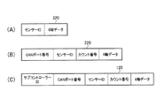
図6(A)は、センサーユニット30のデータ処理部306にて構築されるデータ構造320を示している。データ構造320は、センサーユニット30のIDと6軸データで構成される。データ処理部306は、センサー301x〜301z及び302x〜302zからのデータにセンサーユニット30のIDを付加する。
FIG. 6A shows a
図6(B)は、サブコントローラー20A〜20Bのデータ処理部204にて構築され、メモリ205に格納されるデータ構造220を示している。データ構造220は図6(B)に示すように、図6(A)に示すセンサーユニット30からのデータ構造320に、CANポート22の番号と、カウンター208での同期コマンドのカウント値が付加される。サブコントローラー20A〜20Bは、CANポート22を介してデータが入力されるので、CANポート22の番号と、CANポート22毎のセンサーユニット30のIDにより、最大100個のセンサーユニット30の何れであるかが特定される。図3に示すカウンター208は、開始コマンドにより回数Nがセットされ、例えば同期コマンドが発行される毎に例えばカウントアップされる。カウンター208のカウント値を記録することで、図5に示す何番目の同期コマンドに続くデータであるかが特定される。
FIG. 6B shows a
サブコントローラー20A〜20EにN個目の同期コマンドに対応するデータが入力されると、コマンドデコーダ201にて例えば終了コマンドが発行され、メインコントローラー10に入力される。メインコントローラー10から例えばデータ回収コマンドが発行されると、サブコントローラー20A〜20Eのメモリ205に格納されたデータがメインコントローラー10に出力される。
When data corresponding to the Nth synchronization command is input to the sub-controllers 20A to 20E, for example, an end command is issued by the
図6(C)は、メインコントローラー10のデータ処理部104にて構築され、メモリ105に格納されるデータ構造110を示している。データ構造120は図6(C)に示すように、図6(B)に示すサブコントローラー20A〜20Eからのデータ構造220に、サブコントローラーIDが付加される。図6(C)に示すデータ構造120により、計500個のセンサーユニット30の何れから何時出力されたデータであるかが特定される。なお、図6(A)〜図6(C)に示すセンサーID、CANポート番号及びサブコントローラーIDは、全500個のセンサーユニット30を特定するIDであり、階層的に付与するものに限らない。
FIG. 6C shows a data structure 110 constructed by the
メインコントローラー10のデータ処理部104は、出力時の分解能に合わせるために図6(C)の6軸データの数値に係数を乗算し、あるいは図3に示すカウンター208でのカウント値に対応する時刻を図2の計時部106から求めて、図6(C)のデータ構造に付加することもできる。
The
3.動作確認モード等でのエラー処理
本実施形態の同期計測システム1は、データ計測前に動作確認モードを実施することができる。メインコントローラー10から動作確認コマンドがサブコントローラー20A〜20Eに送信される。サブコントローラー20A〜20Eの各々は、例えばリセットコマンドを全センサーユニット30に送信する。サブコントローラー20A〜20Eの各々からのリセットコマンドに応答して、センサーユニット30からIDが送出される。
これにより、応答の無いセンサーユニット30のエラー情報は、メインコントローラー10により表示部12に表示することができる。
3. Error processing in operation check mode etc. The
Thereby, the error information of the
図7は、センサーユニット30のエラー表示の一例を示している。図7には、5つのサブコントローラー20A〜20Eの各々に対応して、接続されているセンサーユニット30の数の表示領域が設けられている。白抜き表示は正常なセンサーユニット30を示し、黒抜き表示はエラーのあったセンサーユニット30を示している。図7の例では、サブコントローラー20Cの2つ目のCANポート22に接続されたID1のセンサーユニット30にエラー表示されている。これは、そのセンサーユニット30単体の接続不良が原因と考えられる。さらに図7では、サブコントローラー20Dの5つ目のCANポート22に接続されたID1〜ID6のセンサーユニット30にエラー表示されている。これは、5つ目のCANポート22へのCANバスケーブル23の接続不良が原因と考えられる。
FIG. 7 shows an example of an error display of the
このように、同期計測する上で前提となるメインコントローラー10、複数のサブコントローラー20A〜20E及び複数のセンサーユニット30の接続状態は、メインコントローラー10により確認されて表示部12に表示することができる。よって、オペレータは接続不良を修正した上でデータ計測に移行することができる。
As described above, the connection state of the
本実施形態では、計測測途中でエラーが発生した場合では、できるだけ処理を継続し、計測データをメインコントローラー10に保存するようにしている。例えば、サブコントローラー20A〜20Eがセンサーユニット30からの受信できない等の受信データ不正回数が一定数以上になった場合には、1回のみメインコントローラー10にエラー通知し、処理を継続する。また、サブコントローラー20A〜20Eが、あるセンサーユニット30からデータ受信できなくなったことを検知した場合、そのセンサーユニット30に関して初回の検知時のみメインコントローラー10にエラー通知し、処理を継続する。
In the present embodiment, when an error occurs during measurement measurement, the processing is continued as much as possible, and the measurement data is stored in the
サブコントローラー20A〜20Eが、あるCANポート22からデータ受信できなくなったことを検知した場合、そのCANポート22に関して初回の検知時のみメインコントローラー10にエラー通知し、処理を継続する。また、サブコントローラー20A〜20Eのいずれかがトリガ信号を一定時間受信できなかった場合、メインコントローラー10に1回のみエラー通知する。メインコントローラー10は、このエラー通知を受信した場合には、計測処理を強制的に中止する。
When the sub-controllers 20A to 20E detect that data cannot be received from a
メインコントローラー10は、計測終了後にサブコントローラー20A〜20Eのいずれかから計測データをリードする際にエラーが発生した場合、オペレータにサブコントローラー名と共にエラー通知し、正常にリードできるサブコントローラーからはデータリードする。計測データは、メインコントローラー10からの次の計測開始時までサブコントローラー20A〜20E内の不揮発メモリ205に保持する。
When an error occurs when the measurement data is read from any of the sub-controllers 20A to 20E after the measurement is finished, the
なお、上記のように本実施形態について詳細に説明したが、本発明の新規事項および効果から実体的に逸脱しない多くの変形が可能であることは当業者には容易に理解できるであろう。従って、このような変形例はすべて本発明の範囲に含まれるものとする。例えば、明細書又は図面において、少なくとも一度、より、その異なる用語に置き換えることができる。また、メインコントローラー、サブコントローラー、サブコントローラーマスター、サブコントローラースレーブ及びセンサーユニット等の構成、動作も本実施形態で説明したものに限定されず、種々の変形実施が可能である。 Although the present embodiment has been described in detail as described above, it will be easily understood by those skilled in the art that many modifications can be made without departing from the novel matters and effects of the present invention. Accordingly, all such modifications are intended to be included in the scope of the present invention. For example, in the specification or the drawings, the different terms can be replaced at least once. Further, the configurations and operations of the main controller, sub controller, sub controller master, sub controller slave, sensor unit, and the like are not limited to those described in the present embodiment, and various modifications can be made.
1 同期計測システム、10 メインコントローラー、12 表示部、20A〜20E サブコントローラー、20A サブコントローラーマスター、20B〜20E サブコントローラースレーブ、30 センサーユニット 1 synchronous measurement system, 10 main controller, 12 display unit, 20A-20E sub-controller, 20A sub-controller master, 20B-20E sub-controller slave, 30 sensor unit
Claims (10)
前記メインコントローラーに第1の接続経路を介して接続された複数のサブコントローラーと、
前記複数のサブコントローラーに接続された複数のセンサーユニットと、
を有し、
前記複数のサブコントローラーは、サブコントローラーマスターと、前記サブコントローラーマスターに接続されたサブコントローラースレーブと、を含み、
前記メインコントローラーは、前記第1の接続経路を介して前記サブコントローラーマスターに開始コマンドを送出し、
前記サブコントローラーマスターは、前記開始コマンドの受信によりトリガ信号を発生させ、第2の接続経路を介して前記サブコントローラースレーブに前記トリガ信号を送出し、
前記複数のサブコントローラーは、前記トリガ信号に基づいて同期コマンドを前記複数のセンサーユニットに送出し、
前記サブコントローラースレーブは、前記メインコントローラーから前記開始コマンドを受信して、前記トリガ信号の受付けを待機するスタンバイ状態に設定されることを特徴とする同期計測システム。 The main controller,
A plurality of sub-controllers connected to the main controller via a first connection path;
A plurality of sensor units connected to the plurality of sub-controllers;
Have
The plurality of sub-controllers include a sub-controller master and a sub-controller slave connected to the sub-controller master,
The main controller sends a start command to the sub-controller master via the first connection path,
The sub controller master generates a trigger signal by receiving the start command, and sends the trigger signal to the sub controller slave via a second connection path,
The plurality of sub-controllers send a synchronization command to the plurality of sensor units based on the trigger signal ,
The synchronous measurement system according to claim 1, wherein the sub-controller slave is set to a standby state that receives the start command from the main controller and waits for reception of the trigger signal .
前記開始コマンドは、計測回数の情報を含み、
前記サブコントローラーマスターは、前記開始コマンドの受信により、前記計測回数分だけ前記トリガ信号を発生することを特徴とする同期計測システム。 In claim 1,
The start command includes information on the number of measurements,
The synchronous measurement system, wherein the sub-controller master generates the trigger signal for the number of times of measurement upon reception of the start command.
前記開始コマンドは、計測間隔の情報を含むことを特徴とする同期計測システム。 In claim 2,
The synchronous measurement system, wherein the start command includes information on a measurement interval.
前記サブコントローラースレーブは複数設けられ、
前記第2の接続経路は、前記サブコントローラーマスターに前記サブコントローラースレーブが直列に接続されている経路を含むことを特徴とする同期計測システム。 In any one of Claims 1 thru | or 3,
A plurality of the sub-controller slaves are provided,
The second connection path includes a path in which the sub controller slave is connected in series to the sub controller master.
前記トリガ信号はデジタル信号であることを特徴とする同期計測システム。 In any one of Claims 1 thru | or 4,
The synchronous measurement system, wherein the trigger signal is a digital signal.
前記第2の接続経路は、光通信ケーブルを含み、
前記トリガ信号は光信号であることを特徴とする同期計測システム。 In any one of Claims 1 thru | or 5,
The second connection path includes an optical communication cable;
The synchronous measurement system, wherein the trigger signal is an optical signal.
前記第1の接続経路は、インサーネットケーブルを含むことを特徴とする同期計測システム。 In any one of Claims 1 thru | or 6,
Said first connection path, synchronous measurement system characterized in including that the insertion net cables.
前記複数のセンサーユニットは、加速度センサーと角速度センサーとを含むことを特徴とする同期計測システム。 In any one of Claims 1 thru | or 7,
The plurality of sensor units includes an acceleration sensor and an angular velocity sensor.
前記メインコントローラーに接続された表示部をさらに有し、
計測前に実施される動作確認モードにて、前記複数のサブコントローラーからのコマンドに応答して、前記複数のセンサーユニットからIDが送出され、
応答の無いセンサーユニットのエラー情報が前記メインコントローラーにより前記表示部に表示されることを特徴とする同期計測システム。 In any one of Claims 1 thru | or 8,
A display unit connected to the main controller;
In the operation confirmation mode performed before measurement, in response to commands from the plurality of sub-controllers, IDs are sent from the plurality of sensor units,
The synchronous measurement system, wherein error information of a sensor unit having no response is displayed on the display unit by the main controller.
前記複数のサブコントローラーを接続している接続経路と、
前記複数のサブコントローラーに接続された複数のセンサーユニットと、
を有し、
前記複数のサブコントローラーは、サブコントローラーマスターと、前記サブコントローラーマスターに接続されたサブコントローラースレーブと、を含み、
前記サブコントローラーマスターは、メインコントローラーからの開始コマンドの受信した際にトリガ信号を発生させ、前記接続経路を介して前記サブコントローラースレーブに前記トリガ信号を送出し、
前記複数のサブコントローラーは、前記トリガ信号に基づいて同期コマンドを前記複数のセンサーユニットに送出し、
前記サブコントローラースレーブは、前記メインコントローラーから前記開始コマンドを受信して、前記トリガ信号の受付けを待機するスタンバイ状態に設定されることを特徴とする同期計測システム。 Multiple sub-controllers configured to be connectable to the main controller;
A connection path connecting the plurality of sub-controllers;
A plurality of sensor units connected to the plurality of sub-controllers;
Have
The plurality of sub-controllers include a sub-controller master and a sub-controller slave connected to the sub-controller master,
The sub controller master generates a trigger signal when a start command is received from a main controller, and sends the trigger signal to the sub controller slave via the connection path.
The plurality of sub-controllers send a synchronization command to the plurality of sensor units based on the trigger signal ,
The synchronous measurement system according to claim 1, wherein the sub-controller slave is set to a standby state that receives the start command from the main controller and waits for reception of the trigger signal .
Priority Applications (4)
| Application Number | Priority Date | Filing Date | Title |
|---|---|---|---|
| JP2013045158A JP6205756B2 (en) | 2013-03-07 | 2013-03-07 | Synchronous measurement system |
| CN201480011358.2A CN105247816B (en) | 2013-03-07 | 2014-03-03 | Synchronized measurement system |
| PCT/JP2014/001122 WO2014136420A1 (en) | 2013-03-07 | 2014-03-03 | Synchronous measurement system |
| US14/772,509 US9986035B2 (en) | 2013-03-07 | 2014-03-03 | Synchronous measurement system |
Applications Claiming Priority (1)
| Application Number | Priority Date | Filing Date | Title |
|---|---|---|---|
| JP2013045158A JP6205756B2 (en) | 2013-03-07 | 2013-03-07 | Synchronous measurement system |
Publications (3)
| Publication Number | Publication Date |
|---|---|
| JP2014175755A JP2014175755A (en) | 2014-09-22 |
| JP2014175755A5 JP2014175755A5 (en) | 2016-04-21 |
| JP6205756B2 true JP6205756B2 (en) | 2017-10-04 |
Family
ID=51490956
Family Applications (1)
| Application Number | Title | Priority Date | Filing Date |
|---|---|---|---|
| JP2013045158A Active JP6205756B2 (en) | 2013-03-07 | 2013-03-07 | Synchronous measurement system |
Country Status (4)
| Country | Link |
|---|---|
| US (1) | US9986035B2 (en) |
| JP (1) | JP6205756B2 (en) |
| CN (1) | CN105247816B (en) |
| WO (1) | WO2014136420A1 (en) |
Families Citing this family (15)
| Publication number | Priority date | Publication date | Assignee | Title |
|---|---|---|---|---|
| US9711041B2 (en) | 2012-03-16 | 2017-07-18 | Qualcomm Incorporated | N-phase polarity data transfer |
| US9231790B2 (en) * | 2007-03-02 | 2016-01-05 | Qualcomm Incorporated | N-phase phase and polarity encoded serial interface |
| US8064535B2 (en) | 2007-03-02 | 2011-11-22 | Qualcomm Incorporated | Three phase and polarity encoded serial interface |
| JP6205756B2 (en) * | 2013-03-07 | 2017-10-04 | セイコーエプソン株式会社 | Synchronous measurement system |
| WO2015191053A1 (en) * | 2014-06-10 | 2015-12-17 | Halliburton Energy Services, Inc. | Synchronization of receiver units over a control area network bus |
| JP6701622B2 (en) * | 2015-05-07 | 2020-05-27 | セイコーエプソン株式会社 | Synchronous measurement system |
| JP6471705B2 (en) * | 2016-01-29 | 2019-02-20 | オムロン株式会社 | Signal processing apparatus, signal processing apparatus control method, information processing program, and recording medium |
| JP6487386B2 (en) * | 2016-07-22 | 2019-03-20 | ファナック株式会社 | Server, method, program, recording medium, and system for maintaining time accuracy |
| FR3061383B1 (en) * | 2016-12-26 | 2019-05-24 | Stmicroelectronics (Grenoble 2) Sas | SYNCHRONIZATION OF A SENSOR NETWORK |
| JP6888362B2 (en) | 2017-03-27 | 2021-06-16 | セイコーエプソン株式会社 | Detection device, physical quantity measuring device, detection system, electronic device and mobile body |
| US11874101B2 (en) | 2018-04-12 | 2024-01-16 | Faro Technologies, Inc | Modular servo cartridges for precision metrology |
| US10969760B2 (en) * | 2018-04-12 | 2021-04-06 | Faro Technologies, Inc. | Coordinate measurement system with auxiliary axis |
| JP2019215203A (en) * | 2018-06-12 | 2019-12-19 | セイコーエプソン株式会社 | Display device, display method, program, recording medium, and structure monitoring system |
| US11194386B1 (en) * | 2019-05-22 | 2021-12-07 | Facebook Technologies, Llc | Artificial reality wearable magnetic sensor system for body pose tracking |
| KR20220043220A (en) * | 2019-11-18 | 2022-04-05 | 구글 엘엘씨 | Synchronization of sensor output samples |
Family Cites Families (27)
| Publication number | Priority date | Publication date | Assignee | Title |
|---|---|---|---|---|
| JP3152044B2 (en) | 1993-12-15 | 2001-04-03 | 日立電線株式会社 | Hybrid inclinometer |
| US6904110B2 (en) * | 1997-07-31 | 2005-06-07 | Francois Trans | Channel equalization system and method |
| US7085710B1 (en) * | 1998-01-07 | 2006-08-01 | Microsoft Corporation | Vehicle computer system audio entertainment system |
| US8188878B2 (en) * | 2000-11-15 | 2012-05-29 | Federal Law Enforcement Development Services, Inc. | LED light communication system |
| US6965816B2 (en) * | 2001-10-01 | 2005-11-15 | Kline & Walker, Llc | PFN/TRAC system FAA upgrades for accountable remote and robotics control to stop the unauthorized use of aircraft and to improve equipment management and public safety in transportation |
| JP2004080132A (en) * | 2002-08-12 | 2004-03-11 | Yaskawa Electric Corp | Synchronization-detecting method for communication |
| SE0401574D0 (en) * | 2004-06-18 | 2004-06-18 | Henrik Ehrnlund | Wireless sensor network |
| JP2008252882A (en) * | 2007-03-05 | 2008-10-16 | Yaskawa Electric Corp | Serial communication apparatus for sensor and serial communication method |
| WO2009066622A1 (en) * | 2007-11-19 | 2009-05-28 | Nec Corporation | Wireless communication system and method |
| EP2229611A1 (en) * | 2007-11-26 | 2010-09-22 | Vestas Wind Systems A/S | Method and system for registering events in wind turbines of a wind power system |
| US8805595B2 (en) * | 2008-01-17 | 2014-08-12 | General Electric Company | Wind turbine arranged for independent operation of its components and related method and computer program |
| JP4572350B2 (en) * | 2008-03-21 | 2010-11-04 | セイコーエプソン株式会社 | Synchronous detection circuit, detection circuit, physical quantity measuring device, gyro sensor, and electronic equipment |
| CN102014424B (en) * | 2009-12-08 | 2014-08-20 | 电信科学技术研究院 | Measurement reporting method and equipment of carrier aggregation system |
| US9432298B1 (en) * | 2011-12-09 | 2016-08-30 | P4tents1, LLC | System, method, and computer program product for improving memory systems |
| US10021189B2 (en) * | 2012-11-30 | 2018-07-10 | Valmet Automation Oy | Multi-channel sensor measurement method and system |
| JP6205756B2 (en) * | 2013-03-07 | 2017-10-04 | セイコーエプソン株式会社 | Synchronous measurement system |
| JP6155719B2 (en) * | 2013-03-15 | 2017-07-05 | セイコーエプソン株式会社 | Synchronous measurement system |
| CA2911966C (en) * | 2013-05-16 | 2019-04-16 | Enica, Pllc | Automated testing and diagnostic management of building automation and controlled systems |
| GB201311248D0 (en) * | 2013-06-25 | 2013-08-14 | Amantys Ltd | Low-skew communication system |
| GB201311997D0 (en) * | 2013-07-04 | 2013-08-21 | Amantys Ltd | Synchronising parallel power switches |
| CA2856027A1 (en) * | 2014-03-18 | 2015-09-18 | Smartrek Technologies Inc. | Mesh network system and techniques |
| US9281005B2 (en) * | 2014-05-01 | 2016-03-08 | Avago Technologies General Ip (Singapore) Pte. Ltd. | Multiplexed communication in a storage device |
| US9430148B2 (en) * | 2014-05-01 | 2016-08-30 | Avago Technologies General Ip (Singapore) Pte. Ltd. | Multiplexed synchronous serial port communication with skew control for storage device |
| US10293693B2 (en) * | 2015-04-21 | 2019-05-21 | Samsung Electronics Co., Ltd. | Battery control method and apparatus, battery module, and battery pack |
| US9924245B2 (en) * | 2015-05-06 | 2018-03-20 | Crystal Instruments Corporation | Synchronized measurement device using local area network with ethernet messaging |
| JP6701622B2 (en) * | 2015-05-07 | 2020-05-27 | セイコーエプソン株式会社 | Synchronous measurement system |
| US10764026B2 (en) * | 2015-07-20 | 2020-09-01 | Lattice Semiconductor Corporation | Acoustic gesture recognition systems and methods |
-
2013
- 2013-03-07 JP JP2013045158A patent/JP6205756B2/en active Active
-
2014
- 2014-03-03 CN CN201480011358.2A patent/CN105247816B/en active Active
- 2014-03-03 WO PCT/JP2014/001122 patent/WO2014136420A1/en active Application Filing
- 2014-03-03 US US14/772,509 patent/US9986035B2/en active Active
Also Published As
| Publication number | Publication date |
|---|---|
| CN105247816B (en) | 2018-10-16 |
| US9986035B2 (en) | 2018-05-29 |
| JP2014175755A (en) | 2014-09-22 |
| CN105247816A (en) | 2016-01-13 |
| US20160036916A1 (en) | 2016-02-04 |
| WO2014136420A1 (en) | 2014-09-12 |
Similar Documents
| Publication | Publication Date | Title |
|---|---|---|
| JP6205756B2 (en) | Synchronous measurement system | |
| JP6155719B2 (en) | Synchronous measurement system | |
| KR101018542B1 (en) | Control apparatus | |
| US9158644B2 (en) | Autonomous, multi-channel USB data acquisition transducers | |
| US10416704B2 (en) | Method and structure for determining global clock among systems | |
| CN103778090B (en) | Serial communication circuit and method, IC apparatus, physical quantity measuring apparatus | |
| JP5849413B2 (en) | Information communication terminal, biological information measuring device, and information communication system | |
| CN101124542A (en) | System and method for associating a DLPDU received by an interface chip with a data measurement made by an external circuit | |
| JP2014178952A5 (en) | ||
| JP2014175755A5 (en) | ||
| US10375094B2 (en) | Wireless sensor network security | |
| JP3785137B2 (en) | Measurement information transmitting apparatus and multi-point measurement information collecting system | |
| JP2015228171A (en) | Sensor system, sensor, and sensor signal output method | |
| JP4093392B2 (en) | Self-supporting network measurement system | |
| GB2452951A (en) | Control station receives condensed data from wirelessly linked sensing units which store raw data for transmission on receipt of raw data request signal | |
| JP7382015B2 (en) | sensor system | |
| JP3451345B2 (en) | Synchronous control method of photoelectric sensor | |
| US7802150B2 (en) | Ensuring maximum reaction times in complex or distributed safe and/or nonsafe systems | |
| JP4313754B2 (en) | Communication control device | |
| CN113358103B (en) | Distributed measurement architecture processing method of large-scale R-LATs measurement system | |
| JPH0815317A (en) | Wireless probe | |
| JP4469191B2 (en) | Apartment house intercom system | |
| US7352189B2 (en) | Time aligned bussed triggering using synchronized time-stamps and programmable delays | |
| KR20160118049A (en) | Electronic apparatus, asynchronous data transmitting method thereof and optical image stabilization module | |
| JP2007102259A (en) | Sensor system, sensor unit, and sensor management program |
Legal Events
| Date | Code | Title | Description |
|---|---|---|---|
| A521 | Written amendment |
Free format text: JAPANESE INTERMEDIATE CODE: A523 Effective date: 20160304 |
|
| A621 | Written request for application examination |
Free format text: JAPANESE INTERMEDIATE CODE: A621 Effective date: 20160304 |
|
| A131 | Notification of reasons for refusal |
Free format text: JAPANESE INTERMEDIATE CODE: A131 Effective date: 20170110 |
|
| A521 | Written amendment |
Free format text: JAPANESE INTERMEDIATE CODE: A523 Effective date: 20170308 |
|
| TRDD | Decision of grant or rejection written | ||
| A01 | Written decision to grant a patent or to grant a registration (utility model) |
Free format text: JAPANESE INTERMEDIATE CODE: A01 Effective date: 20170808 |
|
| A61 | First payment of annual fees (during grant procedure) |
Free format text: JAPANESE INTERMEDIATE CODE: A61 Effective date: 20170821 |
|
| R150 | Certificate of patent or registration of utility model |
Ref document number: 6205756 Country of ref document: JP Free format text: JAPANESE INTERMEDIATE CODE: R150 |