JP6155719B2 - Synchronous measurement system - Google Patents
Synchronous measurement system Download PDFInfo
- Publication number
- JP6155719B2 JP6155719B2 JP2013053257A JP2013053257A JP6155719B2 JP 6155719 B2 JP6155719 B2 JP 6155719B2 JP 2013053257 A JP2013053257 A JP 2013053257A JP 2013053257 A JP2013053257 A JP 2013053257A JP 6155719 B2 JP6155719 B2 JP 6155719B2
- Authority
- JP
- Japan
- Prior art keywords
- controller
- data
- sub
- controllers
- synchronization
- Prior art date
- Legal status (The legal status is an assumption and is not a legal conclusion. Google has not performed a legal analysis and makes no representation as to the accuracy of the status listed.)
- Active
Links
Images


Classifications
-
- H—ELECTRICITY
- H04—ELECTRIC COMMUNICATION TECHNIQUE
- H04J—MULTIPLEX COMMUNICATION
- H04J3/00—Time-division multiplex systems
- H04J3/02—Details
- H04J3/06—Synchronising arrangements
- H04J3/0635—Clock or time synchronisation in a network
- H04J3/0638—Clock or time synchronisation among nodes; Internode synchronisation
- H04J3/0658—Clock or time synchronisation among packet nodes
-
- G—PHYSICS
- G01—MEASURING; TESTING
- G01D—MEASURING NOT SPECIALLY ADAPTED FOR A SPECIFIC VARIABLE; ARRANGEMENTS FOR MEASURING TWO OR MORE VARIABLES NOT COVERED IN A SINGLE OTHER SUBCLASS; TARIFF METERING APPARATUS; MEASURING OR TESTING NOT OTHERWISE PROVIDED FOR
- G01D18/00—Testing or calibrating apparatus or arrangements provided for in groups G01D1/00 - G01D15/00
-
- H—ELECTRICITY
- H04—ELECTRIC COMMUNICATION TECHNIQUE
- H04L—TRANSMISSION OF DIGITAL INFORMATION, e.g. TELEGRAPHIC COMMUNICATION
- H04L67/00—Network arrangements or protocols for supporting network services or applications
- H04L67/01—Protocols
- H04L67/12—Protocols specially adapted for proprietary or special-purpose networking environments, e.g. medical networks, sensor networks, networks in vehicles or remote metering networks
Description
本発明は、同期計測システム等に関する。 The present invention relates to a synchronous measurement system and the like.
複数のセンサーユニットを被検出体に装着して、被検出体の動き、姿勢、歪等の各種情報を計測することがある。この場合、複数のセンサーユニットの各々から収集されるデータ間には、同期が取られている必要がある。 There are cases where a plurality of sensor units are mounted on a detection object, and various types of information such as movement, posture, and distortion of the detection object are measured. In this case, the data collected from each of the plurality of sensor units needs to be synchronized.
特許文献1では、例えば通信の同期検出のために、マスター通信回路と複数のスレーブ通信回路とが用意される。マスター通信回路は、複数のスレーブ通信回路の一つとの間で通信する際に、通信データに加えて、同期の開始と同期検出用のカウントデータとを、例えば0,1,2,…のように更新して伝送する。このカウントデータを受信することで、複数のスレーブ通信回路の各々は通信の同期タイミングが得られる。
In
特許文献2は、サーバーから計測開始指示を受けるセンサー端末が時計部を内蔵し、センサー端末側にて計測開始時の時刻を時計部から求めて測定データに記録している。
In
特許文献1はマスター通信回路とスレーブ通信回路との間の通信の同期を取るものであって、複数のセンサーユニットの同期を一斉にとるものではない。特許文献1は、通信の同期をとるために、マスター通信回路は、複数のスレーブ通信回路の一つとの間で通信する際に、通信データに加えて、同期の開始と同期検出用のカウントデータとを送出する必要があり、送信する情報量が多く、同期計測には適用できない。
また、特許文献1の同期検出システムは集中型と称することができる。通信の同期は、マスター通信回路からのカウントデータの伝送により、専らマスター通信回路で集中的に管理されるからである。集中型では、マスター通信回路が常時同期検出に関わっているため、マスター通信回路にて同期検出に占有される時間が多く、マスター通信回路本来の機能を発揮する時間が削減されてしまう。
Further, the synchronization detection system of
特許文献2ではセンサー端末にて計側時刻を記録する必要があり、特にサンプリング周波数が高速である同期計測には不向きである。また、数多く設置されるセンサー端末の個々に時計部を搭載することは、コストアップとなる。
In
本発明の幾つかの態様は、コントローラーからの同期開始の指示に基づいてセンサーユニットからコントローラーに送出された計測データの同期タイミングを、コントローラー側で管理することができる同期計測システムを提供することを目的とする。 Some aspects of the present invention provide a synchronous measurement system capable of managing the synchronization timing of measurement data sent from a sensor unit to a controller based on an instruction to start synchronization from the controller on the controller side. Objective.
(1)本発明の一態様は、
コントローラーと、
前記コントローラーに接続されたセンサーユニットと、
を有し、
前記コントローラーは、複数の同期コマンドを所定間隔毎に前記センサーユニットに送出し、
前記センサーユニットは、前記複数の同期コマンドの各一つに同期させて計測データを前記コントローラーに送出し、
前記コントローラーは、
前記センサーユニットからの前記計測データを処理するデータ処理部と、
前記同期コマンドをカウントするカウンターと、
を含み、前記計測データと対応する前記同期コマンドのカウント値を前記計測データに付加したデータ構造を構築する同期計測システムに関する。
(1) One aspect of the present invention is
A controller,
A sensor unit connected to the controller;
Have
The controller sends a plurality of synchronization commands to the sensor unit at predetermined intervals,
The sensor unit sends measurement data to the controller in synchronization with each one of the plurality of synchronization commands,
The controller is
A data processing unit for processing the measurement data from the sensor unit;
A counter for counting the synchronization commands;
And a synchronous measurement system for constructing a data structure in which a count value of the synchronous command corresponding to the measurement data is added to the measurement data.
本発明の一態様では、コントローラーは、センサーユニットから同期コマンド毎に出力される計測データに、同期コマンドのカウント値を付加したデータ構造を構築することから、計測データの同期タイミングを、コントローラー側で管理することができる。それにより、データの欠落や重複が同期コマンドのカウント値から容易に判明する。従って、一つのセンサーユニットからの計測データと他の一つのセンサーユニットからの計測データとの同期を取る上での前提として、各センサーユニットからの同期がとられる計測データには同じカウント値が付されることが担保される。 In one aspect of the present invention, the controller constructs a data structure in which the count value of the synchronization command is added to the measurement data output for each synchronization command from the sensor unit, so that the synchronization timing of the measurement data is set on the controller side. Can be managed. Thereby, missing or duplicated data can be easily determined from the count value of the synchronization command. Therefore, the measurement data from one sensor unit and the measurement data from the other sensor unit are premised on synchronizing the measurement data from each sensor unit with the same count value. To be secured.
(2)本発明の一態様では、前記コントローラーには複数のセンサーユニットが接続され、前記データ構造は、前記複数のセンサーユニットを特定するIDを付すことができる。 (2) In one aspect of the present invention, a plurality of sensor units are connected to the controller, and the data structure can be assigned an ID that identifies the plurality of sensor units.
こうすると、一つのコントローラーに入力される複数のセンサーユニットからの各計測データはIDで区別され、しかも同じカウント値を有する複数の計測データ同士は同期がとられている。 If it carries out like this, each measurement data from the several sensor unit input into one controller will be distinguished by ID, and the several measurement data which have the same count value are synchronized.
(3)本発明の一態様では、前記センサーユニットは、前記同期コマンドをそれぞれ出力する複数のコントローラーの各々に接続することができる。この場合も、同じカウント値を有する複数の計測データ同士は同期がとられている。 (3) In one aspect of the present invention, the sensor unit can be connected to each of a plurality of controllers that output the synchronization commands. Also in this case, a plurality of measurement data having the same count value are synchronized.
(4)本発明の一態様では、前記コントローラーは、前記カウント値が抜けているとき、抜けているカウント値に対応するデータ構造を追加することができる。こうすると、何らかの理由により計測データが欠落しても、全てのカウント値に対応させてデータ構造を構築できる。よつて、同期コマンドのカウント値の順番にデータを並べ替えることで、センサーユニット間での同期のとれたデータ比較が容易となる。 (4) In one aspect of the present invention, when the count value is missing, the controller can add a data structure corresponding to the missing count value. In this way, even if measurement data is lost for some reason, a data structure can be constructed corresponding to all count values. Therefore, by rearranging the data in the order of the count value of the synchronization command, synchronized data comparison between the sensor units is facilitated.
(5)本発明の一態様では、前記追加されたデータ構造中のデータは、エラーデータとすることができる。エラーデータにより、そのカウント値に対応するタイミンクでは計測データが得られなかったことを即座に認識できる。このように欠落したデータをエラーデータにより補う意義は、データ自体の連続性を確保することよりもむしろ、抜けているカウント値による同期ずれを防止することにある。 (5) In one aspect of the present invention, the data in the added data structure may be error data. From the error data, it can be immediately recognized that the measurement data cannot be obtained at the timing corresponding to the count value. The significance of supplementing such missing data with error data is to prevent a synchronization shift due to the missing count value rather than ensuring the continuity of the data itself.
(6)本発明の一態様では、前記追加されたデータ構造中のデータは、前記抜けているカウント値の前後のカウント値に対応するデータに基づいて補間することができる。このように欠落したデータを補間データにより補う意義は、抜けているカウント値による同期ずれを防止すると共に、データ自体の連続性を確保することにある。 (6) In one aspect of the present invention, data in the added data structure can be interpolated based on data corresponding to count values before and after the missing count value. The significance of supplementing missing data with interpolation data in this way is to prevent synchronization loss due to missing count values and to ensure the continuity of the data itself.
(7)本発明の一態様では、前記コントローラーは、同じカウント値を持つ複数のデータ構造が存在する場合に、前記複数のデータ構造の一つを残し、他のデータ構造を削除することができる。これにより、データの重複による同期ずれを防止することができる。 (7) In one aspect of the present invention, when there are a plurality of data structures having the same count value, the controller can leave one of the plurality of data structures and delete another data structure. . As a result, it is possible to prevent synchronization loss due to data duplication.
(8)本発明の一態様では、前記コントローラーは、メインコントローラーと、複数のサブコントローラーとを含み、前記複数のサブコントローラーの各々に前記センサーユニットが接続され、前記複数のサブコントローラーの各々に、前記データ処理部と前記カウンターとを設けることができる。このように、センサーユニットが接続されるコントローラーをサブコントローラーとし、そのサブコントローラーを司る上位のメインコントローラーを設けることができる。 (8) In one aspect of the present invention, the controller includes a main controller and a plurality of sub-controllers, and the sensor unit is connected to each of the plurality of sub-controllers, and each of the plurality of sub-controllers includes: The data processing unit and the counter can be provided. In this way, the controller to which the sensor unit is connected can be used as a sub-controller, and a higher-level main controller that controls the sub-controller can be provided.
(9)本発明の一態様では、前記コントローラーは、メインコントローラーと、複数のサブコントローラーとを含み、前記複数のサブコントローラーの各々に前記センサーユニットが接続され、前記データ処理部は、前記メインコントローラーに設けられた第1のデータ処理部と、前記複数のサブコントローラーの各々に設けられた第2のデータ処理部とを含み、前記第1のデータ処理部が抜けているカウント値又は同じカウント値を持つデータ構造を処理し、前記第2のデータ処理部が、前記複数のサブコントローラーの各々に設けられた前記カウンターのカウント値を前記計測データに付することができる。 (9) In one aspect of the present invention, the controller includes a main controller and a plurality of sub-controllers, the sensor unit is connected to each of the plurality of sub-controllers, and the data processing unit includes the main controller A first data processing unit provided in each of the plurality of sub-controllers and a second data processing unit provided in each of the plurality of sub-controllers, wherein the first data processing unit is missing or the same count value The second data processing unit can attach the count value of the counter provided in each of the plurality of sub-controllers to the measurement data.
このように、データ構造に対するデータ処理の役割を、メインコントローラーとサブコントローラーとで分担させることができる。特に、抜けているカウント値または同一のカウント値を有するデータ構造に対する処理はオフラインで処理可能であることから、メインコントローラーが空き時間にオフライン処理を担うことができる。 In this way, the role of data processing for the data structure can be shared between the main controller and the sub-controller. In particular, since the processing for the missing count value or the data structure having the same count value can be processed offline, the main controller can take offline processing in the idle time.
(10)本発明の一態様では、前記複数のサブコントローラーは、サブコントローラーマスターと、前記サブコントローラーマスターに接続されたサブコントローラースレーブと、を含み、前記メインコントローラーは、少なくとも前記サブコントローラーマスターに開始コマンドを送出し、前記サブコントローラーマスターは、前記開始コマンドの受信によりトリガ信号を発生させ、前記サブコントローラースレーブに前記トリガ信号を送出し、前記複数のサブコントローラーの各々は、前記トリガ信号に基づいて前記同期コマンドを前記複数のセンサーユニットに送出することができる。 (10) In one aspect of the invention, the plurality of sub-controllers include a sub-controller master and a sub-controller slave connected to the sub-controller master, and the main controller starts at least with the sub-controller master. The sub controller master generates a trigger signal upon receipt of the start command, and sends the trigger signal to the sub controller slave. Each of the plurality of sub controllers is based on the trigger signal. The synchronization command can be sent to the plurality of sensor units.
メインコントローラーから開始コマンドを受信したサブコントローラーマスターがトリガ信号を発生し、サブコントローラースレーブに送信する。複数のサブコントローラー(サブコントローラーマスター及びサブコントローラースレーブ)の各々は、トリガ信号に基づいて、複数のセンサーユニットに同期コマンドを送信する。これにより、全サブコントローラーに接続されている全センサーユニットにて一斉に同期を取ることができる。しかも、メインコントローラーは開始コマンドを送出した後は関与せず、複数のサブコントローラーの各々で分散して同期検出することができる。 The sub controller master that receives the start command from the main controller generates a trigger signal and transmits it to the sub controller slave. Each of the plurality of sub-controllers (sub-controller master and sub-controller slave) transmits a synchronization command to the plurality of sensor units based on the trigger signal. As a result, all sensor units connected to all the sub-controllers can be synchronized simultaneously. In addition, the main controller is not involved after sending the start command, and can be detected synchronously in each of the plurality of sub-controllers.
(11)本発明の一態様では、前記センサーユニットは、複数の検出軸を有する、加速度センサーおよび角速度センサーの少なくとも一方を含むことができる。これにより、被検体(人体、移動体、不動産等)の複数個所での動き、姿勢、歪等の各種情報を同期して計測することができる。 (11) In one aspect of the present invention, the sensor unit can include at least one of an acceleration sensor and an angular velocity sensor having a plurality of detection axes. Thereby, various information such as movements, postures, and distortions at a plurality of locations of the subject (human body, mobile body, real estate, etc.) can be measured in synchronization.
以下、本発明の好適な実施の形態について詳細に説明する。なお以下に説明する本実施形態は特許請求の範囲に記載された本発明の内容を不当に限定するものではなく、本実施形態で説明される構成の全てが本発明の解決手段として必須であるとは限らない。 Hereinafter, preferred embodiments of the present invention will be described in detail. The present embodiment described below does not unduly limit the contents of the present invention described in the claims, and all the configurations described in the present embodiment are indispensable as means for solving the present invention. Not necessarily.
1.同期計測システム
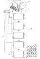
図1は、本実施形態に係る同期計測システム1を示している。図1において、同期計測システム1の少なくとも一つのコントローラーとして、メインコントローラー10と、メインコントローラー10にLAN接続された複数のサブコントローラー20A〜20Eと、を有する。複数のサブコントローラー20A〜20Eの各々には、複数のセンサーユニット30が接続されている。
1. Synchronous Measurement System FIG. 1 shows a
メインコントローラー10は例えばパーソナルコンピューターであり、本体11と、表示部12と、キーボード13と、インサーネットハブ14とを有する。メインコントローラー10は、同期計測システム実行プログラムがインストールされて、5台のサブコントローラー20A〜20Eでの同期計測を制御する。
The
複数のサブコントローラー20A〜20Eは、メインコントローラー10のインサーネットハブ14にインサーネットケーブル15により接続されている。複数のサブコントローラー20A〜20Eの一台はサブコントローラーマスター20Aであり、他の4台はサブコントローラーマスター20Aに接続されたサブコントローラースレーブ20B〜20Eである。
The plurality of
本実施形態では、複数のサブコントローラー20A〜20Eは、例えば光通信ケーブル21によりデイジーチェーン接続されている。つまり、サブコントローラーマスター20Aにサブコントローラースレーブ20Bが接続され、サブコントローラースレーブ20Bにサブコントローラースレーブ20Cが接続され、以下、サブコントローラースレーブ同士が直列に接続されている。こうすると、サブコントローラースレーブの数が増えても、サブコントローラーマスターと複数のサブコントローラースレーブとを直列接続すればよく、スター型接続と比較してケーブル敷設等が容易である。
In the present embodiment, the plurality of
複数のサブコントローラー20A〜20Eの各々は、複数のバスポート例えばCAN(Controller Area Network)バスポート22を有する。なお、CANはエラーやノイズに強い信頼性の高い通信形態であり、同報コマンドが使用できる点で本実施形態に適している。ただし、他のバス仕様であってもよく、CANに限定されない。各CANバスポート22に接続されたCANバスケーブル23には、最大6個のセンサーユニット30が接続されている。複数のサブコントローラー20A〜20Eの各々には8個のCANバスポート22が設けられていることから、複数のサブコントローラー20A〜20Eの各々には最大48個のセンサーユニット30が接続可能である。本実施形態では、サブコントローラーマスター20Aに12個のセンサーユニット30が接続され、サブコントローラースレーブ20B〜20Eの各々には48個のセンサーユニット30が接続され、システム1全体で204個のセンサーユニット30を有する。
Each of the plurality of sub-controllers 20A to 20E has a plurality of bus ports, for example, a CAN (Controller Area Network)
図2は、メインコントローラー10を示すブロック図である。図2において、図1に示す本体11に設けられたCPU101のバスラインには、表示部12及びキーボード13の他に、コマンド発生部102、コマンドデコーダ103、データ処理部104、メモリ105、計時部106及び通信部107等が接続されている。図1に示すインサーネットハブ14は通信部107に接続されている。コマンド発生部102は、例えばセンサーユニット30からのデータを収集する時にはデータ収集開始コマンド(以下、開始コマンド)を発生する。コマンド発生部102は、データ計測前の動作確認モードでは、確認コマンドとして例えばリセットコマンドを発生する。コマンドデコーダ103は、サブコントローラー20A〜20Eからの終了コマンド等をデコードする。データ処理部104については後述する。
FIG. 2 is a block diagram showing the
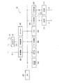
図3は、複数のサブコントローラー20A〜20Eに共通の構成を示すブロック図である。各サブコントローラー20A〜20Eに設けられたCPU201のバスラインには、コマンド発生部202、コマンドデコーダ203、データ処理部204、メモリ205、トリガ発信部206、トリガ受信部207、カウンター208、第1通信部209及び第2通信部210が接続されている。図1に示すインサーネットケーブル15は第1通信部209のポートに接続され、図1にCANポート22は第2通信部210に接続されている。
FIG. 3 is a block diagram showing a configuration common to the plurality of sub-controllers 20A to 20E. A
トリガ発信部206には発光部211が接続され、トリガ受信部207には受光部212が接続される。発光部211または受光部212のいずれかに光通信ケーブル21が接続されることで、光信号であるトリガ信号を発光または受光できるようになっている。サブコントローラーマスター20Aは、発光部211にのみ光通信ケーブル21が接続される。サブコントローラースレーブ20Eは、受光部212にのみ光通信ケーブル21が接続される。サブコントローラー20A〜20Eは、受光部212で受光されたトリガ信号を発光部211に分岐入力させる光スイッチ213を有する。サブコントローラースレーブ20B〜20Dでは光スイッチ213がオンとされ、発光部211及び受光部212の双方に光通信ケーブル21が接続される。それにより、サブコントローラースレーブ20B〜20Dは、上流側から下流側にトリガ信号を転送することができる。その際、上流側からの光信号(トリガ信号)が受光部212で受光されて電気信号に変換された後に、発光部211にて再発光されるので、光信号が波形整形される。トリガ信号をデジタル電気信号で伝送する場合には、サブコントローラースレーブにバッファを設けて波形整形することができる。それにより、同期精度が高まる。また、サブコントローラーマスター20Aでもスイッチ213はオンされ、トリガ発信部206から出力されたトリガ信号)がトリガ受信部207に入力されるようになっている。
A
図4は、センサーユニット30のブロック図を示している。センサーユニット30は、解析対象物体に取り付けられ、所与の物理量を検出する処理を行う。本実施形態では、センサーは、図4にも示すように、少なくとも一つ例えば複数のセンサー301x〜301z及び302x〜302zを含んで構成されている。
FIG. 4 shows a block diagram of the
ここで、本実施形態のセンサーは所与の物理量を検出し、検出した物理量(例えば、加速度、角速度、速度、角加速度など)の大きさに応じた信号(データ)を出力するセンサーである。本実施形態では、X軸、Y軸、Z軸方向の加速度を検出する三軸加速度センサー301x〜301z(慣性センサーの一例)と、X軸、Y軸、Z軸方向の角速度を検出する三軸ジャイロセンサー(角速度センサー、慣性センサーの一例)302x〜302zとからなる6軸モーションセンサーを備えている。
Here, the sensor of the present embodiment is a sensor that detects a given physical quantity and outputs a signal (data) corresponding to the magnitude of the detected physical quantity (for example, acceleration, angular velocity, velocity, angular acceleration, etc.). In the present embodiment,
センサーユニット30は、CPU303のバスラインに、コマンド発生部304、コマンドデコーダ305、データ処理部306及び通信部307等を有することができる。コマンドデコーダ305は、同期コマンドや、確認コマンドとしての例えばリセットコマンド等をデコードする。データ処理部306は、各センサー301x〜301z及び302x〜302zの計測データを、センサーユニット30のIDと対応付けたデータ構造とし、通信部307より出力する。本実施形態では、奇数番目のCANポート22に接続されたセンサーユニット30のIDに1〜6を割り当て、偶数番目のCANポート22に接続されたセンサーユニット30のIDに7〜12を割り当てているが、これに限定されない。例えば、全48個のセンサーユニット30に異なるIDを付与しても良い。データ処理部307は、センサー301x〜301z及び302x〜302zのバイアス補正や温度補正の処理を行うようにしてもよい。なお、バイアス補正や温度補正の機能をセンサー自体に組み込んでもよい。
The
2.同期計測動作
以上のように構成された同期計測システム1での動作について説明する。図1に示すメインコントローラー10のキーボード13を操作することで、計測が開始される。メインコントローラー10は、コマンド発生部102にて開始コマンドを生成する。この開始コマンドでは、計測回数Nを指定することができる。この開始コマンドは、図2に示す通信部107、インサーネットハブ14、インサーネットケーブル15(図1)を介して全てのサブコントローラー20A〜20Eに送出される。メインコントローラー10から複数のサブコントローラー20A〜20Eに至る開始コマンドの送信に、同期の精度が求められるわけではない。
2. Synchronous measurement operation The operation of the
サブコントローラー20A〜20Eの各々は、図3に示す第1通信部209にて開始コマンドを受信し、コマンドデコーダ203にてデコードされる。サブコントローラーマスター20Aは、図5に示すように、開始コマンドの受信によりトリガ発信部206にて例えばデジタル信号であるトリガ信号を発生させ、発光部211にて光信号として出力する。
Each of the sub-controllers 20A to 20E receives the start command by the
サブコントローラーマスター20Aでは、図3に示すスイッチ213がオンしているので、トリガ発信部206にて発信されたトリガ信号がスイッチ213を介してトリガ受信部207に入力され、トリガ信号Aが受信される(図5参照)。
In the
一方、サブコントローラースレーブ20B〜20Eの各々は、第1通信部209を介して、メインコントローラー10からの開始コマンドが受信され、コマンドデコーダ203にてデコードされる。それにより、サブコントローラースレーブ20B〜20Eの各々は、トリガ信号の受信を待機するスタンバイ状態に設定することができる。
On the other hand, each of the
その後、サブコントローラースレーブ20B〜20Eの各々は、サブコントローラーマスター20Aからのトリガ信号が、直接または上流側のサブコントローラースレーブを介して、受光部212で受光され、トリガ受信部207にてトリガ信号B〜トリガ信号Eを受信する(図5参照)。本実施形態では、トリガ信号としてデジタル信号を光通信にて伝送している。図5に示すように、トリガ信号のエッジにより同期タイミングを取ることができる。よって、開始コマンドの発行から図5に示すトリガ信号A〜トリガ信号Eが受信されるまでの時間ずれT1は数nSオーダーであり、無視できる。
Thereafter, in each of the
サブコントローラー20A〜20Eの各々は、トリガ受信部207にてトリガ信号が受信されると、図3に示すコマンド発生部202がトリガ信号のエッジに基づいて同期コマンドを発生する。サブコントローラー20A〜20Eの各々では、第2通信部210よりCANポート22を介して、同期コマンドを同報により複数のセンサーユニット30に送出する。
In each of the sub-controllers 20A to 20E, when the trigger signal is received by the
サブコントローラー20A〜20Eの各々に接続された複数のセンサーユニット30の各々では、サブコントローラー20A〜20Eからの同期コマンドA〜Eがコマンドデコーダ305にてデコードされる(図5参照)。図5に示す同期コマンドA〜Eの時間ずれT2は、トリガ信号A〜トリガ信号Eの時間ずれT1よりももちろん大きいが、数μSオーダーであり、無視できる。
In each of the plurality of
センサーユニット30の各センサー301x〜301z及び302x〜302zでは計測データが計測されており、データ処理部306は同期コマンドに同期したデータのみを所定フォーマットのデータ構造として通信部307より出力する。ただし、センサーユニット30は同期コマンドに同期させて計測を開始し、かつ、計測データを出力するようにしても良い。本実施形態では、同期コマンドが入力された後の最初のデータが出力される。サブコントローラー20Aでは同期コマンドAの入力後の最初のデータがデータ1として出力される。同様にして、例えばサブコントローラー20Eでは同期コマンドEの入力後の最初のデータがデータ1として出力される。なお本実施形態では、各センサーユニット30は高速サンプリングしており、そのサンプリング周波数は例えば1kHzである。この場合、T2≦1mSであれば同期ずれが生じない。本実施形態ではT2がμSオーダーであるので、同期計測が可能となる。
Measurement data is measured in each of the
上述したように、開始コマンドは計測回数Nを含むことができ、N≧2の場合にはサブコントローラー20Aは、所定間隔毎にN個のトリガ信号を繰り返し発生させる(図5参照)。そして、センサーユニット30では、N個のトリガ信号の各々に基づいて、上述した計測データ1〜Nがサブコントローラー20Aに出力される。
As described above, the start command can include the number N of measurement times, and when N ≧ 2, the sub-controller 20A repeatedly generates N trigger signals at predetermined intervals (see FIG. 5). In the
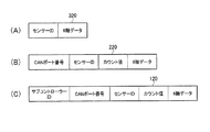
図6(A)は、センサーユニット30のデータ処理部306にて構築されるデータ構造320を示している。データ構造320は、センサーユニット30のIDと6軸データで構成される。データ処理部306は、センサー301x〜301z及び302x〜302zからのデータにセンサーユニット30のIDを付加する。
FIG. 6A shows a
図6(B)は、サブコントローラー20A〜20Bのデータ処理部204にて構築され、メモリ205に格納されるデータ構造220を示している。データ構造220は図6(B)に示すように、図6(A)に示すセンサーユニット30からのデータ構造320に、CANポート22の番号と、カウンター208での同期コマンドのカウント値が付加される。サブコントローラー20A〜20Bは、CANポート22を介してデータが入力されるので、CANポート22の番号と、CANポート22毎のセンサーユニット30のIDにより、最大48個のセンサーユニット30の何れであるかが特定される。図3に示すカウンター208は、開始コマンドにより回数Nがセットされ、例えば同期コマンドが発行される毎に例えばカウントアップされる。カウンター208のカウント値を記録することで、図5に示す何番目の同期コマンドに続くデータであるかが特定される。
FIG. 6B shows a
サブコントローラー20A〜20EにN個目の同期コマンドに対応するデータが入力されると、コマンドデコーダ201にて例えば終了コマンドが発行され、メインコントローラー10に入力される。メインコントローラー10から例えばデータ回収コマンドが発行されると、サブコントローラー20A〜20Eのメモリ205に格納されたデータがメインコントローラー10に出力される。
When data corresponding to the Nth synchronization command is input to the sub-controllers 20A to 20E, for example, an end command is issued by the
図6(C)は、メインコントローラー10のデータ処理部104にて構築され、メモリ105に格納されるデータ構造110を示している。データ構造120は図6(C)に示すように、図6(B)に示すサブコントローラー20A〜20Eからのデータ構造220に、サブコントローラーIDが付加される。図6(C)に示すデータ構造120により、計204個のセンサーユニット30の何れから何時出力されたデータであるかが特定される。なお、図6(A)〜図6(C)に示すセンサーID、CANポート番号及びサブコントローラーIDは、全204個のセンサーユニット30を特定するIDであり、階層的に付与するものに限らない。例えば全204個のセンサーユニット30に異なるセンサーIDを付与しても良い。こうすると、CANポート番号及びサブコントローラーIDは不要となる。
FIG. 6C shows a data structure 110 constructed by the
メインコントローラー10のデータ処理部104は、出力時の分解能に合わせるために図6(C)の6軸データの数値に係数を乗算し、あるいは図3に示すカウンター208でのカウント値に対応する時刻を図2の計時部106から求めて、図6(C)のデータ構造に付加することもできる。
The
3.カウント値の飛び番または重複を解消するデータ処理
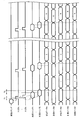
図7〜図11は、メインコントローラー10のデータ処理部(第1のデータ処理部ともいう)104または複数のサブコントローラー20A〜20Eの各々に配置されたデータ処理部(第2のデータ処理部ともいう)204に実施される処理を説明するためのデータ列を示している。図7〜図11に示すデータ列は、ある一つのセンサーユニット30にて計測された6軸データである。図7〜図11に示すデータ列は、図3に示すカウンター208のサンプリングカウント値が6軸データに付され、サンプリングカウント値でソーティングされて配列されている。
3. Data Processing for Eliminating Count Number Duplication or Duplication FIGS. 7 to 11 are arranged in the data processing unit (also referred to as first data processing unit) 104 of the
図7に示すデータ列には飛び番(抜けているカウント値)があり、サンプリングカウント値「10」に対応するデータが脱落している。つまり、例えばサブコントローラー20Aのコマンド発生部202が10番目の同期コマンドを発行してセンサーユニット30に送出したが、それに対応する計測データがセンサーユニット30からサブコントローラー20Aに送信されなかった例である。
The data string shown in FIG. 7 has skip numbers (missing count values), and data corresponding to the sampling count value “10” is missing. That is, for example, the
データ処理部104またはデータ処理部204は、図7に示すようにデータ列中のサンプリングカウント値が飛び番であるとき、飛び番に対応するデータ構造を図8または図9に示すように追加することができる。こうすると、何らかの理由により計測データが欠落しても、全てのカウント値に対応させてデータ構造を構築できる。よつて、同期コマンドのカウント値の順番にデータを並べ替えることで、センサーユニット30間での同期のとれたデータ比較が容易となる。
When the sampling count value in the data string is a jump number as shown in FIG. 7, the
図8に示すように、カウント値「10」として追加されたデータは、エラーデータとすることができる。エラーデータとは、計測データとしての有効範囲外のデータを意味する。エラーデータの追加により、そのカウント値に対応するタイミンクでは計測データが得られなかったことを即座に認識できる。このように欠落したデータをエラーデータにより補う意義は、データ自体の連続性を確保することよりもむしろ、飛び番による同期ずれを防止することにある。 As shown in FIG. 8, the data added as the count value “ 10 ” can be error data. Error data means data outside the valid range as measurement data. By adding error data, it is possible to immediately recognize that measurement data could not be obtained at the timing corresponding to the count value. The significance of supplementing the missing data with error data in this way is to prevent a synchronization shift due to skipping rather than ensuring the continuity of the data itself.
あるいは、図9に示すように、カウント値「10」として追加されたデータは、飛び番の前後のカウント値「9」及び「11」に対応するデータに基づいて補間、例えば線形補間することができる。このように欠落したデータを補間データにより補う意義は、飛び番による同期ずれを防止すると共に、データ自体の連続性を確保することにある。 Alternatively, as shown in FIG. 9, the data added as the count value “ 10 ” can be interpolated, for example, linearly interpolated based on the data corresponding to the count values “ 9 ” and “ 11 ” before and after the skip number. it can. The significance of supplementing the missing data with the interpolation data is to prevent synchronization deviation due to skipping and to ensure the continuity of the data itself.
図10は、同じカウント値「10」を持つ複数のデータが存在する例を示している。つまり、例えばサブコントローラー20Aのコマンド発生部202が10番目の同期コマンドを発行してセンサーユニット30に送出した後であって、11番目の同期コマンドを発行する前に、センサーユニット30から2度に亘って計測データがサブコントローラー20Aに送信された例である。
FIG. 10 shows an example in which a plurality of data having the same count value “10” exists. That is, for example, after the
データ処理部104またはデータ処理部204は、図10に示すようにデータ列中のサンプリングカウント値「10」に対応するデータが重複して存在する時、サンプリングカウント値「10」に対応する2つのデータの一方を残し、他方のデータを削除することができる。これにより、データの重複による同期ずれを防止することができる。
As shown in FIG. 10, the
上述した図8、図9または図11に示すデータ処理は、サブコントローラー20A〜20Eの各々に設けられたデータ処理部(第2のデータ処理部)204にて実施しても良いし、メインコントローラー10のデータ処理部(第1のデータ処理部)104にて実施しても良い。特に、抜けているカウント値(飛び番)または同一のカウント値を有するデータ構造に対する処理はオフラインで処理可能であることから、メインコントローラー10が空き時間にオフライン処理を担うことができる。それにより、サブコントローラー20A〜20Eの負担を軽減することができる。
The data processing shown in FIG. 8, FIG. 9, or FIG. 11 described above may be performed by the data processing unit (second data processing unit) 204 provided in each of the sub-controllers 20A to 20E, or the main controller Ten data processing units (first data processing units) 104 may be used. In particular, since the processing for the missing count value (jump number) or the data structure having the same count value can be processed offline, the
4.動作確認モード等でのエラー処理
本実施形態の同期計測システム1は、データ計測前に動作確認モードを実施することができる。メインコントローラー10から動作確認コマンドがサブコントローラー20A〜20Eに送信される。サブコントローラー20A〜20Eの各々は、例えばリセットコマンドを全センサーユニット30に送信する。サブコントローラー20A〜20Eの各々からのリセットコマンドに応答して、センサーユニット30からIDが送出される。
これにより、応答の無いセンサーユニット30のエラー情報は、メインコントローラー10により表示部12に表示することができる。
4). Error processing in operation check mode etc. The
Thereby, the error information of the
図12は、センサーユニット30のエラー表示の一例を示している。図12には、5つのサブコントローラー20A〜20Eの各々に対応して、接続されているセンサーユニット30の数の表示領域が設けられている。白抜き表示は正常なセンサーユニット30を示し、黒抜き表示はエラーのあったセンサーユニット30を示している。図12の例では、サブコントローラー20Cの2つ目のCANポート22に接続されたID1のセンサーユニット30にエラー表示されている。これは、そのセンサーユニット30単体の接続不良が原因と考えられる。さらに図12では、サブコントローラー20Dの5つ目のCANポート22に接続されたID1〜ID6のセンサーユニット30にエラー表示されている。これは、5つ目のCANポート22へのCANバスケーブル23の接続不良が原因と考えられる。
FIG. 12 shows an example of error display of the
このように、同期計測する上で前提となるメインコントローラー10、複数のサブコントローラー20A〜20E及び複数のセンサーユニット30の接続状態は、メインコントローラー10により確認されて表示部12に表示することができる。よって、オペレータは接続不良を修正した上でデータ計測に移行することができる。
As described above, the connection state of the
本実施形態では、計測測途中でエラーが発生した場合では、できるだけ処理を継続し、計測データをメインコントローラー10に保存するようにしている。例えば、サブコントローラー20A〜20Eがセンサーユニット30からの受信できない等の受信データ不正回数が一定数以上になった場合には、1回のみメインコントローラー10にエラー通知し、処理を継続する。また、サブコントローラー20A〜20Eが、あるセンサーユニット30からデータ受信できなくなったことを検知した場合、そのセンサーユニット30に関して初回の検知時のみメインコントローラー10にエラー通知し、処理を継続する。
In the present embodiment, when an error occurs during measurement measurement, the processing is continued as much as possible, and the measurement data is stored in the
サブコントローラー20A〜20Eが、あるCANポート22からデータ受信できなくなったことを検知した場合、そのCANポート22に関して初回の検知時のみメインコントローラー10にエラー通知し、処理を継続する。また、サブコントローラー20A〜20Eのいずれかがトリガ信号を一定時間受信できなかった場合、メインコントローラー10に1回のみエラー通知する。メインコントローラー10は、このエラー通知を受信した場合には、エラーのあったサブコントローラーの計測処理を強制的に中止することができる。
When the sub-controllers 20A to 20E detect that data cannot be received from a
メインコントローラー10は、計測終了後にサブコントローラー20A〜20Eのいずれかから計測データをリードする際にエラーが発生した場合、オペレータにサブコントローラー名と共にエラー通知し、正常にリードできるサブコントローラーからはデータリードする。計測データは、メインコントローラー10からの次の計測開始時までサブコントローラー20A〜20E内の不揮発メモリ205に保持する。
When an error occurs when the measurement data is read from any of the sub-controllers 20A to 20E after the measurement is finished, the
なお、上記のように本実施形態について詳細に説明したが、本発明の新規事項および効果から実体的に逸脱しない多くの変形が可能であることは当業者には容易に理解できるであろう。従って、このような変形例はすべて本発明の範囲に含まれるものとする。例えば、明細書又は図面において、少なくとも一度、より、その異なる用語に置き換えることができる。また、メインコントローラー、サブコントローラー、サブコントローラーマスター、サブコントローラースレーブ及びセンサーユニット等の構成、動作も本実施形態で説明したものに限定されず、種々の変形実施が可能である。例えば、上述した実施形態における有線接続は無線接続に置き換えることができる。 Although the present embodiment has been described in detail as described above, it will be easily understood by those skilled in the art that many modifications can be made without departing from the novel matters and effects of the present invention. Accordingly, all such modifications are intended to be included in the scope of the present invention. For example, in the specification or the drawings, the different terms can be replaced at least once. Further, the configurations and operations of the main controller, sub controller, sub controller master, sub controller slave, sensor unit, and the like are not limited to those described in the present embodiment, and various modifications can be made. For example, the wired connection in the above-described embodiment can be replaced with a wireless connection.
1 同期計測システム、10 メインコントローラー(コントローラー)、20A〜20E サブコントローラー(コントローラー)、20A サブコントローラーマスター(コントローラー)、20B〜20E サブコントローラースレーブ(コントローラー)、30 センサーユニット、120,220 データ構造、104,204 データ処理部、104 第1のデータ処理部、204 第2のデータ処理部、208 カウンター
1 Synchronous measurement system, 10 Main controller (controller), 20A to 20E Sub controller (controller), 20A Sub controller master (controller), 20B to 20E Sub controller slave (controller), 30 sensor units, 120, 220 Data structure, 104 204
Claims (11)
前記コントローラーに接続されたセンサーユニットと、
を有し、
前記コントローラーは、複数の同期コマンドを所定間隔で前記センサーユニットに送出し、
前記センサーユニットは、前記複数の同期コマンドに同期させて計測データを前記コントローラーに送出し、
前記コントローラーは、
前記センサーユニットからの前記計測データを処理するデータ処理部と、
前記同期コマンドをカウントするカウンターと、を含み、
前記計測データと対応する前記同期コマンドのカウント値を前記計測データに付加したデータ構造を構築することを特徴とする同期計測システム。 A controller,
A sensor unit connected to the controller;
Have
The controller sends a plurality of synchronization commands to the sensor unit at predetermined intervals,
The sensor unit sends measurement data to the controller in synchronization with the plurality of synchronization commands,
The controller is
A data processing unit for processing the measurement data from the sensor unit;
A counter for counting the synchronization command,
A synchronous measurement system characterized by constructing a data structure in which a count value of the synchronous command corresponding to the measurement data is added to the measurement data.
前記コントローラーには複数のセンサーユニットが接続され、
前記データ構造は、前記複数のセンサーユニットを特定するIDが付加されていることを特徴とする同期計測システム。 In claim 1,
A plurality of sensor units are connected to the controller,
An ID for specifying the plurality of sensor units is added to the data structure.
前記同期コマンドを出力する複数の前記コントローラーと、複数の前記センサーユニットと、を含み、
前記センサーユニットは、複数の前記コントローラーのいずれか一つに接続されていることを特徴とする同期計測システム。 In claim 1,
A plurality of the controllers that output the synchronization command; and a plurality of the sensor units;
The synchronous measurement system, wherein the sensor unit is connected to any one of the plurality of controllers.
前記コントローラーに接続されたセンサーユニットと、
を有し、
前記コントローラーは、複数の同期コマンドを所定間隔で前記センサーユニットに送出し、
前記センサーユニットは、前記複数の同期コマンドに同期させて計測データを前記コントローラーに送出し、
前記コントローラーは、
前記センサーユニットからの前記計測データを処理するデータ処理部と、
前記同期コマンドをカウントするカウンターと、を含み、
前記計測データと対応する前記同期コマンドのカウント値を前記計測データに付加したデータ構造を構築し、
前記コントローラーは、前記カウント値が抜けているとき、抜けているカウント値に対応するデータ構造を追加して構築することを特徴とする同期計測システム。 A controller,
A sensor unit connected to the controller;
Have
The controller sends a plurality of synchronization commands to the sensor unit at predetermined intervals,
The sensor unit sends measurement data to the controller in synchronization with the plurality of synchronization commands,
The controller is
A data processing unit for processing the measurement data from the sensor unit;
A counter for counting the synchronization command,
Constructing a data structure in which the count value of the synchronization command corresponding to the measurement data is added to the measurement data;
When the count value is missing, the controller builds by adding a data structure corresponding to the missing count value.
前記追加して構築されたデータ構造中の前記計測データに対応するデータは、エラーデータであることを特徴とする同期計測システム。 In claim 4,
The synchronous measurement system, wherein data corresponding to the measurement data in the additionally constructed data structure is error data.
前記追加して構築されたデータ構造中の前記計測データに対応するデータは、前記抜けているカウント値の前後のカウント値に対応する前記計測データに基づいて補間処理されたデータであることを特徴とする同期計測システム。 In claim 4,
The data corresponding to the measurement data in the additionally constructed data structure is data interpolated based on the measurement data corresponding to the count values before and after the missing count value. Synchronous measurement system.
前記コントローラーに接続されたセンサーユニットと、
を有し、
前記コントローラーは、複数の同期コマンドを所定間隔で前記センサーユニットに送出し、
前記センサーユニットは、前記複数の同期コマンドに同期させて計測データを前記コントローラーに送出し、
前記コントローラーは、
前記センサーユニットからの前記計測データを処理するデータ処理部と、
前記同期コマンドをカウントするカウンターと、を含み、
前記計測データと対応する前記同期コマンドのカウント値を前記計測データに付加したデータ構造を構築し、
前記コントローラーは、同じカウント値を持つ複数のデータ構造が存在する場合に、前記複数のデータ構造の一つを残し、他のデータ構造を削除することを特徴とする同期計測システム。 A controller,
A sensor unit connected to the controller;
Have
The controller sends a plurality of synchronization commands to the sensor unit at predetermined intervals,
The sensor unit sends measurement data to the controller in synchronization with the plurality of synchronization commands,
The controller is
A data processing unit for processing the measurement data from the sensor unit;
A counter for counting the synchronization command,
Constructing a data structure in which the count value of the synchronization command corresponding to the measurement data is added to the measurement data;
The synchronous measurement system, wherein when there are a plurality of data structures having the same count value, the controller leaves one of the plurality of data structures and deletes the other data structures.
前記コントローラーは、メインコントローラーと、複数のサブコントローラーとを含み、
前記複数のサブコントローラーに前記センサーユニットが接続され、
前記複数のサブコントローラーに、前記データ処理部と前記カウンターとが設けられていることを特徴とする同期計測システム。 In any one of Claims 1 thru | or 7,
The controller includes a main controller and a plurality of sub-controllers,
The sensor unit is connected to the plurality of sub-controllers,
The synchronous measurement system, wherein the plurality of sub-controllers are provided with the data processing unit and the counter.
前記コントローラーは、メインコントローラーと、複数のサブコントローラーとを含み、
前記複数のサブコントローラーに前記センサーユニットが接続され、
前記データ処理部は、前記メインコントローラーに設けられた第1のデータ処理部と、前記複数のサブコントローラーに設けられた第2のデータ処理部とを含み、
前記第1のデータ処理部が抜けているカウント値又は同じカウント値を持つデータ構造を処理し、
前記第2のデータ処理部が、前記複数のサブコントローラーに設けられた前記カウンターのカウント値を前記計測データに付加することを特徴とする同期計測システム。 In any one of Claims 4 thru | or 7,
The controller includes a main controller and a plurality of sub-controllers,
The sensor unit is connected to the plurality of sub-controllers,
The data processing unit includes a first data processing unit provided in the main controller, and a second data processing unit provided in the plurality of sub-controllers,
The first data processing unit processes a missing count value or a data structure having the same count value;
The synchronous measurement system, wherein the second data processing unit adds count values of the counters provided in the plurality of sub-controllers to the measurement data.
前記複数のサブコントローラーは、サブコントローラーマスターと、前記サブコントローラーマスターに接続されたサブコントローラースレーブと、を含み、
前記メインコントローラーは、少なくとも前記サブコントローラーマスターに開始コマンドを送出し、
前記サブコントローラーマスターは、前記開始コマンドの受信によりトリガ信号を発生させ、前記サブコントローラースレーブに前記トリガ信号を送出し、
前記複数のサブコントローラーは、前記トリガ信号に基づいて前記同期コマンドを前記複数のセンサーユニットに送出することを特徴とする同期計測システム。 In claim 8 or 9,
The plurality of sub-controllers include a sub-controller master and a sub-controller slave connected to the sub-controller master,
The main controller sends a start command to at least the sub-controller master,
The sub controller master generates a trigger signal by receiving the start command, and sends the trigger signal to the sub controller slave.
The plurality of sub-controllers send out the synchronization command to the plurality of sensor units based on the trigger signal.
前記センサーユニットは、複数の検出軸を有する、加速度センサーおよび角速度センサーの少なくとも一方を含むことを特徴とする同期計測システム。 In any one of Claims 1 thru | or 10,
The synchronous measurement system, wherein the sensor unit includes at least one of an acceleration sensor and an angular velocity sensor having a plurality of detection axes.
Priority Applications (4)
| Application Number | Priority Date | Filing Date | Title |
|---|---|---|---|
| JP2013053257A JP6155719B2 (en) | 2013-03-15 | 2013-03-15 | Synchronous measurement system |
| US14/773,912 US9948418B2 (en) | 2013-03-15 | 2014-03-07 | Synchronous measurement system |
| PCT/JP2014/001272 WO2014141651A1 (en) | 2013-03-15 | 2014-03-07 | Synchronous measurement system |
| CN201480012826.8A CN105027174B (en) | 2013-03-15 | 2014-03-07 | Synchronized measurement system |
Applications Claiming Priority (1)
| Application Number | Priority Date | Filing Date | Title |
|---|---|---|---|
| JP2013053257A JP6155719B2 (en) | 2013-03-15 | 2013-03-15 | Synchronous measurement system |
Publications (3)
| Publication Number | Publication Date |
|---|---|
| JP2014178952A JP2014178952A (en) | 2014-09-25 |
| JP2014178952A5 JP2014178952A5 (en) | 2016-04-28 |
| JP6155719B2 true JP6155719B2 (en) | 2017-07-05 |
Family
ID=51536330
Family Applications (1)
| Application Number | Title | Priority Date | Filing Date |
|---|---|---|---|
| JP2013053257A Active JP6155719B2 (en) | 2013-03-15 | 2013-03-15 | Synchronous measurement system |
Country Status (4)
| Country | Link |
|---|---|
| US (1) | US9948418B2 (en) |
| JP (1) | JP6155719B2 (en) |
| CN (1) | CN105027174B (en) |
| WO (1) | WO2014141651A1 (en) |
Families Citing this family (13)
| Publication number | Priority date | Publication date | Assignee | Title |
|---|---|---|---|---|
| JP6205756B2 (en) * | 2013-03-07 | 2017-10-04 | セイコーエプソン株式会社 | Synchronous measurement system |
| JP6701622B2 (en) | 2015-05-07 | 2020-05-27 | セイコーエプソン株式会社 | Synchronous measurement system |
| CN107870681A (en) * | 2016-09-23 | 2018-04-03 | 上海葡萄纬度科技有限公司 | The method and corresponding bracelet and computing device of Real time identification action |
| JP6888362B2 (en) | 2017-03-27 | 2021-06-16 | セイコーエプソン株式会社 | Detection device, physical quantity measuring device, detection system, electronic device and mobile body |
| DE102017210959A1 (en) * | 2017-06-28 | 2019-01-03 | Trumpf Werkzeugmaschinen Gmbh + Co. Kg | Machine tool with a plurality of sensors |
| US10475654B2 (en) * | 2017-08-31 | 2019-11-12 | Taiwan Semiconductor Manufacturing Company, Ltd. | Wrap-around contact plug and method manufacturing same |
| US11193803B2 (en) | 2018-02-02 | 2021-12-07 | Analog Devices International Unlimited Company | Measurement system |
| JP6939664B2 (en) | 2018-03-14 | 2021-09-22 | オムロン株式会社 | Sensor management device, sensor information synchronization method, control program, and recording medium |
| JP7077694B2 (en) * | 2018-03-19 | 2022-05-31 | セイコーエプソン株式会社 | Sensor modules, measurement systems, electronic devices, and moving objects |
| JP6950612B2 (en) | 2018-03-30 | 2021-10-13 | オムロン株式会社 | Sensors, information processing devices, sensor control methods, information processing methods, programs, and recording media |
| JP2019215203A (en) * | 2018-06-12 | 2019-12-19 | セイコーエプソン株式会社 | Display device, display method, program, recording medium, and structure monitoring system |
| CN108931495A (en) * | 2018-06-28 | 2018-12-04 | 首都师范大学 | Terahertz time-domain spectroscopy synchronized measurement system and method |
| KR20220109932A (en) * | 2021-01-29 | 2022-08-05 | 삼성전자주식회사 | Electronic device for synchronizing time of different data records and method thereof |
Family Cites Families (12)
| Publication number | Priority date | Publication date | Assignee | Title |
|---|---|---|---|---|
| JPS56158548A (en) * | 1980-05-09 | 1981-12-07 | Nec Corp | Frame synchronism returning circuit |
| JPS6227813A (en) * | 1985-07-29 | 1987-02-05 | Hitachi Ltd | Phase synchronization system |
| CN2053746U (en) * | 1989-06-10 | 1990-02-28 | 河北省沧州地震局电子研究所 | Patrol measuring transmission device for single cable and multi-way |
| JPH03104496A (en) * | 1989-09-19 | 1991-05-01 | Ricoh Co Ltd | Telemeter system |
| JPH09130871A (en) * | 1995-11-02 | 1997-05-16 | Yokogawa Electric Corp | Time series data transmitter |
| JP3524466B2 (en) * | 2000-04-18 | 2004-05-10 | 株式会社ミツトヨ | Data output device and method |
| JP2004080132A (en) * | 2002-08-12 | 2004-03-11 | Yaskawa Electric Corp | Synchronization-detecting method for communication |
| JP4575736B2 (en) * | 2004-09-28 | 2010-11-04 | 三井造船株式会社 | Collapse detection apparatus and method |
| JP4926752B2 (en) | 2007-02-23 | 2012-05-09 | 三菱電機株式会社 | Distributed measurement system and method |
| JP2009271731A (en) * | 2008-05-07 | 2009-11-19 | Takashi Kurokawa | Sensing system |
| JP5346726B2 (en) * | 2009-07-24 | 2013-11-20 | 株式会社キーエンス | Continuous sensor system, network unit, and sensor unit |
| JP2011253341A (en) * | 2010-06-02 | 2011-12-15 | Panasonic Corp | Radio sensor system |
-
2013
- 2013-03-15 JP JP2013053257A patent/JP6155719B2/en active Active
-
2014
- 2014-03-07 US US14/773,912 patent/US9948418B2/en active Active
- 2014-03-07 CN CN201480012826.8A patent/CN105027174B/en active Active
- 2014-03-07 WO PCT/JP2014/001272 patent/WO2014141651A1/en active Application Filing
Also Published As
| Publication number | Publication date |
|---|---|
| WO2014141651A1 (en) | 2014-09-18 |
| US20160036544A1 (en) | 2016-02-04 |
| JP2014178952A (en) | 2014-09-25 |
| US9948418B2 (en) | 2018-04-17 |
| CN105027174A (en) | 2015-11-04 |
| CN105027174B (en) | 2019-07-30 |
Similar Documents
| Publication | Publication Date | Title |
|---|---|---|
| JP6155719B2 (en) | Synchronous measurement system | |
| JP6205756B2 (en) | Synchronous measurement system | |
| CN105915781B (en) | Method for synchronizing results of multiple vision system processors | |
| JP6477161B2 (en) | INFORMATION PROCESSING APPARATUS, INFORMATION PROCESSING PROGRAM, AND INFORMATION PROCESSING METHOD | |
| JP6140459B2 (en) | Sensor data transmission device | |
| US7924888B2 (en) | Method for exchanging data between stations from different networks | |
| CN103778090B (en) | Serial communication circuit and method, IC apparatus, physical quantity measuring apparatus | |
| JP4901813B2 (en) | Multi-controller system | |
| JP2014178952A5 (en) | ||
| JP5876240B2 (en) | Device and control device for manipulating interface signals | |
| JP5191934B2 (en) | Status monitoring system and status monitoring method | |
| US7079046B2 (en) | Multi-point data acquisition apparatus | |
| JP2010060502A (en) | Measurement recorder system | |
| CN103733030B (en) | Sensor device with sampling functions and employ the sensing data disposal system of this sensor device | |
| KR20130023190A (en) | Communication apparatus | |
| JPH0793614B2 (en) | Series controller | |
| US20080144535A1 (en) | Ring-type network and fairness execution program for ring-type network | |
| JP4313754B2 (en) | Communication control device | |
| JP4880273B2 (en) | Sensor system | |
| JP4469191B2 (en) | Apartment house intercom system | |
| US20050117574A1 (en) | Data transmission system, terminal device, data transmission method, and recording medium | |
| JPS6325754B2 (en) | ||
| KR20160118049A (en) | Electronic apparatus, asynchronous data transmitting method thereof and optical image stabilization module | |
| JPH03168899A (en) | Monitor and control system and transmitting method | |
| JP2021175096A (en) | Network apparatus |
Legal Events
| Date | Code | Title | Description |
|---|---|---|---|
| A521 | Written amendment |
Free format text: JAPANESE INTERMEDIATE CODE: A523 Effective date: 20160311 |
|
| A621 | Written request for application examination |
Free format text: JAPANESE INTERMEDIATE CODE: A621 Effective date: 20160311 |
|
| A131 | Notification of reasons for refusal |
Free format text: JAPANESE INTERMEDIATE CODE: A131 Effective date: 20170307 |
|
| A521 | Written amendment |
Free format text: JAPANESE INTERMEDIATE CODE: A523 Effective date: 20170421 |
|
| TRDD | Decision of grant or rejection written | ||
| A01 | Written decision to grant a patent or to grant a registration (utility model) |
Free format text: JAPANESE INTERMEDIATE CODE: A01 Effective date: 20170509 |
|
| A61 | First payment of annual fees (during grant procedure) |
Free format text: JAPANESE INTERMEDIATE CODE: A61 Effective date: 20170522 |
|
| R150 | Certificate of patent or registration of utility model |
Ref document number: 6155719 Country of ref document: JP Free format text: JAPANESE INTERMEDIATE CODE: R150 |