JP6204121B2 - Motor drive system and electric railway vehicle equipped with the system - Google Patents
Motor drive system and electric railway vehicle equipped with the system Download PDFInfo
- Publication number
- JP6204121B2 JP6204121B2 JP2013186143A JP2013186143A JP6204121B2 JP 6204121 B2 JP6204121 B2 JP 6204121B2 JP 2013186143 A JP2013186143 A JP 2013186143A JP 2013186143 A JP2013186143 A JP 2013186143A JP 6204121 B2 JP6204121 B2 JP 6204121B2
- Authority
- JP
- Japan
- Prior art keywords
- voltage
- pwm
- motor
- phase
- harmonic
- Prior art date
- Legal status (The legal status is an assumption and is not a legal conclusion. Google has not performed a legal analysis and makes no representation as to the accuracy of the status listed.)
- Active
Links
Images


Description
本発明は、交流電動機あるいは交流発電機の駆動システムに関し、例えば、電気鉄道車両、電気自動車、産業用インバータ、風力発電システム、ディーゼル発電機システム等における回転機の制御装置に関する。 The present invention relates to an AC motor or an AC generator drive system, for example, a control device for a rotating machine in an electric railway vehicle, an electric vehicle, an industrial inverter, a wind power generation system, a diesel generator system, and the like.
近年の省エネ、地球環境保全の世界的な動向に連動して、電力変換装置(以下、「インバータ」と称す)で駆動される交流電動機(以下、「モータ」と称す)が様々な製品に適用されている。中でも、電気鉄道車両や風力発電システムなど、モータ容量の大きな分野へ拡大している。特に、電気鉄道用のモータ駆動システムは、高効率を達成するために、モータ本体の高効率化やそれを駆動する変換器の高効率化が進められている。 AC motors (hereinafter referred to as “motors”) driven by power converters (hereinafter referred to as “inverters”) are applied to various products in conjunction with recent global trends in energy conservation and global environmental conservation. Has been. Above all, it is expanding to fields with large motor capacity such as electric railway vehicles and wind power generation systems. In particular, in order to achieve high efficiency in motor drive systems for electric railways, higher efficiency of the motor body and higher efficiency of the converter that drives the motor body are being promoted.
一般に、モータを可変速駆動するためには、直流電力を任意の周波数と電圧に変換するインバータが用いられる。そのインバータは、半導体スイッチング素子を用いた主回路と前記スイッチング素子を制御する制御器から構成され、前記スイッチング素子を任意のキャリア周波数でパルス幅変調制御(以下、「PWM制御」と称す)することにより、モータへの印加電圧および周波数を制御してモータの可変速駆動を行っている。 In general, in order to drive a motor at a variable speed, an inverter that converts DC power into an arbitrary frequency and voltage is used. The inverter is composed of a main circuit using a semiconductor switching element and a controller for controlling the switching element, and the switching element is subjected to pulse width modulation control (hereinafter referred to as “PWM control”) at an arbitrary carrier frequency. Thus, the variable voltage drive of the motor is performed by controlling the voltage and frequency applied to the motor.
しかしながら、モータをインバータで可変速駆動すると、PWM制御のキャリア高調波によって、モータの固定子や回転子鉄心および導体で発生する損失が増加し、モータ効率が低下する。このモータで発生するキャリア高調波の損失は、キャリア周波数の増加に伴って減少することが知られているが、従来のPWM制御においてキャリア周波数の増加はインバータのスイッチング損失の増加につながるため、特に電気鉄道用システムなどの大容量のモータ駆動システムにおいてはキャリア周波数を十分高くすることができないことが多い。
このため、インバータによるモータ駆動システムにおいて、インバータのスイッチング回数が少ない場合にはモータ電流の高調波を抑制し、インバータおよびモータを含めたドライブシステム全体での損失を低減するような制御技術の開発が必要である。
However, when the motor is driven at a variable speed by an inverter, losses generated in the stator, rotor core, and conductor of the motor increase due to PWM control carrier harmonics, and the motor efficiency decreases. It is known that the loss of carrier harmonics generated in this motor decreases as the carrier frequency increases. However, in the conventional PWM control, the increase in carrier frequency leads to an increase in switching loss of the inverter. In a large-capacity motor drive system such as an electric railway system, the carrier frequency cannot often be made sufficiently high.
For this reason, in motor drive systems using inverters, if the number of inverter switchings is small, the development of control technology that suppresses harmonics in the motor current and reduces losses in the entire drive system including the inverter and motor has been developed. is necessary.
モータ駆動システムにおける損失は、大きく分けて2つある。一つはモータが発生する損失であり、もう一つはインバータで発生する損失である。さらに、モータの発生する損失は、基本波成分に起因した損失(以下、「基本波損失」と称す)と、インバータによって発生する高調波に起因した損失(以下、「高調波損失」と称す)に分けられる。また、インバータで発生する損失は、スイッチング素子のオンオフ動作に起因した損失(以下、「スイッチング損失」と称す)と、スイッチング素子の導通時に発生する損失(以下、「導通損失」と称す)に分けられる。 There are roughly two losses in the motor drive system. One is a loss generated by the motor, and the other is a loss generated by the inverter. Furthermore, the loss generated by the motor is the loss caused by the fundamental wave component (hereinafter referred to as “fundamental wave loss”) and the loss caused by the harmonic generated by the inverter (hereinafter referred to as “harmonic loss”). It is divided into. The loss generated in the inverter is divided into a loss caused by the on / off operation of the switching element (hereinafter referred to as “switching loss”) and a loss generated during conduction of the switching element (hereinafter referred to as “conduction loss”). It is done.
電気鉄道車両では、特許文献1に示すように、高速域においてスイッチング回数が増加しないように、PWM制御時のパルス数を制御するような工夫をしている。一般的には、モータの駆動周波数とPWMを行う際のキャリア周波数を同期させてパルスを生成する、同期PWM方式を採用し、余分な高調波の発生を防ぐと同時に、スイッチング回数が増加することを抑えている。
In electric railway vehicles, as shown in
また、インバータのスイッチング損失を低減する手法に関しては、二相変調方式が三相インバータのスイッチング損失を低減する方式として広く知られている。二相変調方式は、三相のうち二相をスイッチング制御し残り一相はスイッチングしない方式で、正弦波PWM方式と比べスイッチング回数は2/3となるため、スイッチング損失を低減できる。例えば、特許文献2に記載されているように、インバータの負荷率に応じてインバータ損失が最小となるように制御する2アーム変調方式のPWM制御方法がある。
As for a method for reducing the switching loss of the inverter, the two-phase modulation method is widely known as a method for reducing the switching loss of the three-phase inverter. The two-phase modulation method is a method in which two of the three phases are switched and the remaining one phase is not switched. The number of times of switching is 2/3 compared to the sine wave PWM method, so that switching loss can be reduced. For example, as described in
また、モータの高調波損失を低減する手法に関しては、特許文献3、特許文献4、特許文献5および特許文献6に開示された技術がある。特許文献3では、モータの高調波損失の割合を計算し、それに応じてインバータのスイッチング回数およびスイッチ角を調整する技術が示されている。特許文献4では、モータの駆動電流に含まれる駆動周波数の3n次高調波電流を検出し、その高調波電流を打ち消すように目標電圧を補正することで高調波電流によるモータ損失を低減する技術が示されている。特許文献5では、正弦波形の変調波の最大振幅が、PWM制御の三角波キャリアの最大振幅を超えないよう変調波を歪ませ、高調波電流の増加を抑制する技術が示されている。また、特許文献6では、電圧の基本波信号に高調波成分を意図的に重畳させ、特定の周波数のトルク脈動を消去または低減する技術が示されている。
Further, regarding the technique for reducing the harmonic loss of the motor, there are techniques disclosed in
特許文献1に開示の技術は、多パルスモードと1パルスモードの組合せにより出力電圧の大きさを零から最大電圧までの全出力電圧領域をほぼ連続的に制御するものであり、パルスモードの切替時において、電流やトルクの脈動を低減することができる。しかしながら、多パルスモードから1パルスモードまでをつなぐ際の過変調制御モードのPWM電圧波形は、出力電圧を増やせる代わりに電圧波形のひずみが増加することになり、5次や7次といった低次の高調波成分が多く含まれる。そのため、正弦波変調によるPWM電圧波形に比べモータの高調波損失が増大する課題があった。
The technology disclosed in
特許文献2に開示の技術は、2アーム変調方式のPWM制御において、各相アーム出力電圧の飽和を指定する各飽和区間を、インバータの出力電圧と出力電流とのなす力率角に応じて、それぞれ同一角度の移動修正をするものである。しかしながら、二相変調方式はインバータ装置のスイッチング損失を低減することはできるが、必ずしもモータ損失を低減する効果は得られない。むしろ、モータ電流が歪み、モータ損失が増加する場合がある。
In the technique disclosed in
特許文献3に開示の技術は、正規化した高調波損失を正規化した基本波電力で除した値が最小となるようにスイッチ角を調整するものである。しかしながら、特許文献3で開示されている高調波損失を正規化した値PHの算出式では、インバータ電圧波形に含まれる高調波電圧を最小化することはできても、その結果、必ずしもモータの高調波損失が最小になるとは限らない。また、高調波電流の各成分の二乗和の平方根(以下、「全高調波電流」と称す)の値を低減しても、モータの高調波損失が同様に低減しないことが知られている。そのため、インバータのスイッチ角の調整によって低次高調波を低減することが必ずしもモータ損失の低減につながらない。
The technique disclosed in
特許文献4に開示の技術は、三相6線式のモータ等において、従来のPWM制御ではモータの駆動電流に3n次の高調波(モータ駆動電流の周波数の3n倍の高調波)が打ち消されないため、その3n次高調波電流を検出し、その高調波電流を打ち消すように目標電圧を補正することで、高調波電流によるモータ損失を低減するものである。しかしながら、開示された方法は、モータ構造によって生じる高調波電流を低減する手法であり、従来のPWM制御のキャリア高調波によって生じるモータ損失を低減するものではない。また、検出した高調波電流の周波数成分を打ち消すような電圧を出力するためには、インバータのスイッチング回数もそれ相応に多く必要になり、インバータ損失が増加する恐れがある。また、高調波電流を検出するためには、高性能な電流センサを用いる必要がある、といった課題もある。
In the technology disclosed in
特許文献5に開示の技術は、正弦波形の変調波の最大振幅がPWM制御の三角波キャリアの最大振幅を超えないよう変調波を歪ませ、高調波電流の増加を抑制するものである。しかしながら、この変調方式は、高調波電流の増加を抑制するためには高いキャリア周波数が必要であり、電機鉄道用システムなどの大容量のモータ駆動システムにおいてキャリア周波数の設定が低い用途では、むしろ、PWM電圧波形の歪みが大きくなり、モータ損失が増加する。また、この変調方式における最大出力電圧は、従来の1パルスモードの出力電圧を1とした場合、約0.9までしか出力できず、電圧利用率が1割も低下してしまう課題がある。その結果、従来の1パルス駆動に比べて一次電流が増加し、モータ損失が増加する場合がある。
The technology disclosed in
特許文献6に開示の技術は、スイッチング回数を低減しつつ電流脈動を抑制する方式として、電圧の基本波信号に高調波成分を意図的に重畳させ、特定の周波数のトルク脈動を消去または低減するものである。しかしながら、開示された方法は、特定の低次高調波の消去または低減が可能であるが、消去・低減した次数以外の高調波電流が増加することが知られている。そのため、特定の低次高調波を消去または低減することが必ずしもモータ損失の低減につながらない場合がある。また、スイッチング損失を低減するためにはスイッチング回数を下げる必要があるが、スイッチング回数を低下させると電流脈動が増大し、これに伴うモータの脈動トルクや騒音が大きくなる問題が生じる恐れがあり、それをあまり許容することができない。
The technique disclosed in
モータ駆動システムで発生する損失について、スイッチング周波数が基本波電圧の周波数に対して低くなると、PWM電圧に含まれる高調波電圧が増加してモータの高調波損失が増加するため、モータの運転効率の点からすれば、スイッチング周波数は高い方が望ましい。
一方、インバータでは、スイッチング素子のオンオフ動作に伴う損失が大きくなるほど、インバータに高い冷却性能が求められるため、インバータのスイッチング損失の点からすれば、スイッチング周波数は低い方が望ましい。
Regarding the loss generated in the motor drive system, when the switching frequency is lower than the fundamental voltage, the harmonic voltage included in the PWM voltage increases and the harmonic loss of the motor increases. From a point of view, a higher switching frequency is desirable.
On the other hand, in the inverter, the higher the loss associated with the on / off operation of the switching element, the higher the cooling performance required for the inverter. Therefore, in terms of the switching loss of the inverter, the switching frequency is preferably low.
そのため、モータ駆動システムの高効率化の観点では、スイッチング周波数は同一条件下において、PWM電圧の歪みを低減してモータ効率を向上させる手法が望まれる。
また、これらの損失は、モータの駆動状態における基本波電圧、基本波電流、力率、インバータのスイッチング周波数およびスイッチング方式、インバータの入力直流電圧など、様々な要因によって変化する。これらの損失について、各々を独立に最小化するのでは、必ずしもシステム全体の最小化を達成できるものではなく、システムのトータルとしての効率最大化が必要である。
Therefore, from the viewpoint of increasing the efficiency of the motor drive system, a technique is desired that improves the motor efficiency by reducing the distortion of the PWM voltage under the same switching frequency.
These losses vary depending on various factors such as the fundamental wave voltage, fundamental wave current, power factor, inverter switching frequency and switching method, and inverter input DC voltage in the driving state of the motor. Minimizing each of these losses independently does not necessarily achieve minimization of the entire system, but it is necessary to maximize the efficiency of the system as a whole.
したがって、本発明の目的は、上記の課題に鑑み、PWM電圧の歪み率(高調波含有率)および高調波電流を低減し、モータの運転効率を向上させるモータ駆動システム、インバータおよびモータの制御方法を提供することにある。また、モータ駆動システムの負荷や直流電圧などの運転状況に応じて、インバータのスイッチング周波数、あるいはパルス数を変更することで、高調波損失を低減し効率の最大化を実現する。さらに、モータの発生する基本波損失、このモータを駆動するインバータの損失ならびにインバータの高調波によって発生する損失の大小関係から、全損失の最小化を実現する。 Therefore, in view of the above problems, an object of the present invention is to reduce a distortion rate (harmonic content) and a harmonic current of a PWM voltage and improve a motor driving efficiency, an inverter, and a motor control method. Is to provide. Further, by changing the switching frequency or the number of pulses of the inverter according to the operating conditions such as the load of the motor drive system and DC voltage, the harmonic loss is reduced and the efficiency is maximized. Further, the total loss can be minimized from the magnitude relationship of the fundamental wave loss generated by the motor, the loss of the inverter driving the motor, and the loss generated by the harmonics of the inverter.
上記課題を達成するために、本発明に係るモータ駆動システムにおいて、モータ駆動用インバータへ供給するゲートパルス信号をパルス幅変調するPWM信号制御部は、三相各相の電圧指令信号に基づく基本波電圧指令のゼロクロス点を含むその近傍の位相領域でパルス信号のオン動作とオフ動作をそれぞれ1回以上挿入し、かつ基本波電圧指令の正負ピーク点を含むその付近の位相領域でパルス信号のオン動作とオフ動作をそれぞれ1回以上挿入し、かつそれ以外の位相領域ではパルス信号をオン状態またはオフ状態に保持する、ゲートパルス信号を生成する。 In order to achieve the above object, in the motor drive system according to the present invention, the PWM signal control unit that performs pulse width modulation on the gate pulse signal supplied to the motor drive inverter includes a fundamental wave based on the voltage command signal of each of the three phases. Insert a pulse signal ON / OFF operation at least once in the neighboring phase region including the zero cross point of the voltage command, and turn on the pulse signal in the neighboring phase region including the positive / negative peak point of the fundamental voltage command. An operation and an off operation are inserted at least once, and a gate pulse signal is generated that holds the pulse signal in an on state or an off state in other phase regions.
本発明によれば、インバータからモータへ供給されるPWM電圧の歪み率あるいは高調波電圧を低減することにより、それに伴うモータおよびインバータの損失を低減しモータの運転効率を向上させるインバータを提供することができる。また、本発明の望ましい実施形態に関わるモータ駆動システムによれば、モータの負荷状態に応じて、モータ駆動システム全体の効率を最大にして制御することが可能になる。 According to the present invention, there is provided an inverter that reduces the distortion rate or harmonic voltage of the PWM voltage supplied from the inverter to the motor, thereby reducing the loss of the motor and the inverter and improving the driving efficiency of the motor. Can do. In addition, according to the motor drive system according to the preferred embodiment of the present invention, it is possible to control the motor drive system with the maximum efficiency according to the load state of the motor.
以下、図面を用いて、本発明の実施形態として実施例1〜実施例10について、順に説明する。なお、同一の要素については、全ての図において原則として同一の符号を付している。また、同一の機能を有する部分については説明を省略する。 Hereinafter, Examples 1 to 10 will be described in order as embodiments of the present invention with reference to the drawings. In addition, about the same element, the same code | symbol is attached | subjected in principle in all the figures. Further, description of portions having the same function is omitted.
図2は、本発明の実施例1によるモータの駆動システムの構成図である。
本駆動システムは、制御対象であるモータ103、モータ103を駆動するインバータ102、モータ103のトルク指令Tm*を発生するトルク指令発生器105、トルク指令Tm*に一致したトルクを発生するためにインバータ102の制御を行う制御器101、モータ103に流れる電流を検出する電流検出部121およびモータ103に接続された負荷器104から構成される。
FIG. 2 is a configuration diagram of a motor drive system according to the first embodiment of the present invention.
This drive system includes a
インバータ102は、インバータに電力を供給する入力端子123a、123b、6個のスイッチング素子Sup〜Swnで構成されるインバータ主回路部132、インバータ主回路部132を直接駆動するゲート・ドライバ133、インバータ102の過電流保護用に取り付けた直流抵抗器134および平滑用のコンデンサ131から構成される。
The
また、インバータ102は、電流検出部121による交流電流検出値Iu、Iv、Iwと回転速度検出部122によるモータ103の回転電気角周波数ωrを基に、制御器101により制御される。なお、図2の電流検出部121は3相検出による交流電流検出の構成としているが、2相検出としてもよい。また、相電流センサを用いず、直流抵抗器134を流れる電流値から推定される交流電流値を用いてもよい。さらに、図2のモータの回転速度検出部122によるモータ103の回転電気角周波数ωrを用いない、速度センサレスおよび位置センサレスの構成としてもよい。
The
トルク指令発生器105は、制御器101の上位に位置し、モータ103へのトルク指令Tm*を発生する。制御器101は、トルク指令発生器105のトルク指令Tm*に基づき、インバータ102を介してモータ103の発生トルクを制御する。
The
制御器101は、ベクトル制御器111により、モータ103の交流電流検出値である三相交流電流検出値Iu、Iv、Iwをトルク電流成分(q軸電流成分)と励磁電流成分(d軸電流成分)に分離して、それぞれの電流制御を行う。この電流制御の結果、回転座標軸であるdq軸上の電圧指令Vd*ならびにVq*が演算され、それらを極座標変換器112により電圧振幅指令V1*と電圧位相指令δに変換する。また、ベクトル制御器111により、電圧指令の一次周波数f1も演算され、位相演算部114へと出力される。位相演算部114は、この電圧指令の一次周波数f1を入力とし制御位相θdを演算する。さらに、加算器201において、前記電圧指令位相δと前記制御位相θdを加算して電圧位相θvを出力する。前記電圧振幅指令V1*は、前記電圧位相θvに基づき、三相座標変換器113において三相交流電圧指令Vu*、Vv*、Vw*に変換される。この三相交流電圧指令Vu*、Vv*、Vw*は、PWM(パルス幅変調)制御器115によって、インバータ102を駆動するPWMパルス信号に変換される。
The
PWM制御器115は、キャリア周波数fcに基づいて三角波キャリアを発生し、その三角波キャリア、PWMパルスモード信号Psおよび前記三相交流電圧指令Vu*、Vv*、Vw*に基づく変調波との大小比較を行い、パルス幅変調を実施する。このパルス幅変調された信号によって、インバータ102のスイッチング素子をオン/オフ制御する。
The
また、キャリア周波数fcおよびPWMパルスモード信号Psは、PWMキャリア決定器116において演算される。PWMキャリア決定器116は、電圧振幅指令V1*と電圧指令の一次周波数f1に基づいて、キャリア周波数fcおよびPWMパルスモード信号Psを決定する。
The carrier frequency fc and the PWM pulse mode signal Ps are calculated by the
一般的に、回転機を駆動制御するために、本発明のモータ駆動システムのようにインバータが用いられる。その主回路には、高速・大容量の制御素子IGBTを使用したインバータが専ら利用され、高速スイッチングに適した三角波比較PWMなどのスイッチング方式がインバータ制御の主流となっている。 In general, an inverter is used as in the motor drive system of the present invention to drive and control a rotating machine. In the main circuit, an inverter using a high-speed, large-capacity control element IGBT is exclusively used, and a switching method such as a triangular wave comparison PWM suitable for high-speed switching is the mainstream of inverter control.
PWM制御は、供給される直流電圧をオン・オフスイッチングしパルス幅を変化させて平均電圧を制御する方式であり、この平均電圧を可変させることでモータを制御する。その制御方式に、電圧指令となる正弦波形の変調波と三角波形のPWMキャリアを比較して、電圧パルス波形を生成する方式(以下、「正弦波変調方式」と称す)がある。 The PWM control is a method of controlling the average voltage by switching on and off the supplied DC voltage and changing the pulse width, and controls the motor by varying the average voltage. As a control method, there is a method of generating a voltage pulse waveform by comparing a sinusoidal modulation wave serving as a voltage command with a triangular waveform PWM carrier (hereinafter referred to as “sine wave modulation method”).
一般に、PWMキャリアは、変調波の整数倍の周波数を選び同期させる必要があるが、PWMキャリアと変調波の周波数比が十分に大きい場合は、非同期としても実用上ほとんど問題はない。そのため、PWMキャリア周波数が数kHzから数十kHzと高く設定できる一般産業用途向けでは、非同期PWMを採用する。 Generally, it is necessary to select and synchronize the PWM carrier with a frequency that is an integral multiple of the modulation wave. However, when the frequency ratio between the PWM carrier and the modulation wave is sufficiently large, there is almost no problem in practical use even if it is asynchronous. Therefore, asynchronous PWM is employed for general industrial applications where the PWM carrier frequency can be set as high as several kHz to several tens of kHz.
図3に、正弦波変調方式における、変調波および三角波キャリア(a)、相電圧パルス波形(b)、線間電圧パルス波形(c)、線間電圧を周波数解析したときの電圧高調波分布(d)および相電流をFFT(高速フーリエ変換)による周波数解析したときの電流高調波分布(e)の一例を示す。
正弦波変調方式のPWM波形に含まれる高調波成分は、三角波キャリアの側帯波として生じる。三角波キャリア周波数fc、変調波の基本波周波数をf1とすると、m・fc±n・f1(m、nは整数)となる周波数の高調波成分が生じる。ただし、共通のPWMキャリアを使用した場合、あるいはPWMキャリアと変調波の周波数比を3の倍数かつ奇数とした場合は、三相出力において、n=0の高調波成分はキャンセルされる。図3では、変調波の基本波周波数f1と三角波キャリアfcの比を20倍として(fc=20・f1)、三相交流電圧指令のPWM制御において共通キャリアとしている。
FIG. 3 shows a modulation wave and triangular wave carrier (a), phase voltage pulse waveform (b), line voltage pulse waveform (c), voltage harmonic distribution when frequency analysis is performed on the line voltage in the sine wave modulation method ( An example of current harmonic distribution (e) when frequency analysis is performed on d) and phase current by FFT (Fast Fourier Transform) is shown.
The harmonic component contained in the sinusoidal modulation PWM waveform is generated as a sideband wave of the triangular wave carrier. Assuming that the triangular wave carrier frequency fc and the fundamental wave frequency of the modulation wave are f1, harmonic components having a frequency of m · fc ± n · f1 (m and n are integers) are generated. However, when a common PWM carrier is used, or when the frequency ratio between the PWM carrier and the modulated wave is a multiple of 3 and odd, the harmonic component of n = 0 is canceled in the three-phase output. In FIG. 3, the ratio of the fundamental wave frequency f1 of the modulation wave to the triangular wave carrier fc is set to 20 times (fc = 20 · f1), and the carrier is used as a common carrier in the PWM control of the three-phase AC voltage command.
図4に、図3と同様の波形および分布について、変調波の振幅の大きさを変えた場合を示す。正弦波変調方式の高調波分布の特徴として、図3に示したように変調率が低い(変調波の振幅が小さい)ときは、PWMキャリア周波数の側帯波は、2・fc±f1や2・fc±5・f1の場合(図3の2fc側帯波)に高調波成分が多いが、図4に示したように変調率が高くなる(変調波の振幅が大きくなる)と、PWMキャリア周波数の側帯波成分は、2・fc±f1や2・fc±5・f1の場合(図4の2fc側帯波)よりも、fc±2・f1やfc±4・f1の場合(図4のfc側帯波)が多くなっていることがわかる。このように、同じ相電圧パルス数でも、出力する基本波電圧の大きさを変えると、PWM電圧波形の高調波電圧分布が変わることがわかる。 FIG. 4 shows a case where the amplitude of the modulated wave is changed for the same waveform and distribution as in FIG. As a characteristic of the harmonic distribution of the sine wave modulation method, when the modulation rate is low (the amplitude of the modulation wave is small) as shown in FIG. 3, the sideband of the PWM carrier frequency is 2 · fc ± f1 or 2 · In the case of fc ± 5 · f1 (2fc sideband in FIG. 3), there are many harmonic components, but when the modulation rate becomes high (the amplitude of the modulation wave increases) as shown in FIG. 4, the PWM carrier frequency The sideband component is more in the case of fc ± 2 · f1 and fc ± 4 · f1 than the case of 2 · fc ± f1 and 2 · fc ± 5 · f1 (2fc sideband in FIG. 4) (the fc sideband in FIG. 4). It can be seen that the waves are increasing. Thus, it can be seen that even if the number of phase voltage pulses is the same, the harmonic voltage distribution of the PWM voltage waveform changes when the magnitude of the output fundamental wave voltage is changed.
モータをインバータで駆動すると、PWM信号のキャリア高調波によって、モータの固定子・回転子鉄心および導体で発生する損失が増加し、正弦波電圧によるモータ駆動時に比べてモータ効率は低下することになる。一般に、インバータ高調波によって誘導電動機に発生する高調波損失は、キャリア周波数の増加に伴って減少することが知られている。しかしながら、電気鉄道車両ドライブシステムのような大容量システムの場合には、キャリア周波数を高く設定することは困難であり、通常、数100Hzから2kHz程度に設定される。これは、電気鉄道車両用途では1台のインバータで4台の誘導モータを並列駆動することから、インバータのスイッチング素子は、大電流が流れた状態でオン・オフスイッチングするため、一般産業用途に比べて、スイッチング素子の温度制約条件からキャリア周波数を上げることができない点が挙げられる。また、鉄道車両用途では、信号保安システムへの誘導障害の影響が出ないようにするため、キャリア周波数を低く設定しなければならないことがある。 When the motor is driven by an inverter, the loss generated in the stator / rotor core and the conductor of the motor is increased due to the carrier harmonics of the PWM signal, and the motor efficiency is reduced as compared to when the motor is driven by a sine wave voltage. . In general, it is known that harmonic loss generated in an induction motor due to inverter harmonics decreases as the carrier frequency increases. However, in the case of a large-capacity system such as an electric railway vehicle drive system, it is difficult to set the carrier frequency high, and it is usually set to several hundred Hz to about 2 kHz. This is because, in an electric railway vehicle application, four induction motors are driven in parallel by one inverter, and the switching element of the inverter is turned on / off in a state where a large current flows, so that it is compared with general industrial applications. Thus, the carrier frequency cannot be increased due to the temperature constraint condition of the switching element. In railcar applications, it may be necessary to set the carrier frequency low in order to prevent the effects of inductive interference on the signal security system.
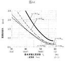
図5に、基本波電圧周波数f1とキャリア周波数fcならびに相電圧パルス数Nの関係を示す。前述したように、出力電圧の電気角1周期あたりのパルス数を増やすことで高調波電圧は低減するが、一方では、インバータ素子のスイッチング回数が増加し、それによりインバータのスイッチング損失は増加する。このインバータのスイッチング損失が大きくなるほど、インバータは発熱し高い冷却性能が求められるため、図5に示すように、一般にキャリア周波数fcには上限値が存在する。そして、基本波電圧周波数f1が増加するに従い、相電圧パルス数Nが低下することになる。図5の非同期モード領域において基本波電圧周波数f1が低い領域では、基本波電圧周波数f1に対してキャリア周波数fcが十分高いため、交流電圧のひずみは小さいが、基本波電圧の周波数が高くなると出力するPWM電圧波形のひずみが大きくなる。その結果、相電圧パルス数Nが低下すると、非同期PWM方式では、三角波キャリアと変調波の位相関係によって出力電圧の変動や高調波の増大といった問題が生じる。 FIG. 5 shows the relationship between the fundamental voltage frequency f1, the carrier frequency fc, and the number N of phase voltage pulses. As described above, the harmonic voltage is reduced by increasing the number of pulses per electrical angle cycle of the output voltage, but on the other hand, the switching frequency of the inverter element is increased, thereby increasing the switching loss of the inverter. As the switching loss of the inverter increases, the inverter generates heat and high cooling performance is required. Therefore, as shown in FIG. 5, there is generally an upper limit value for the carrier frequency fc. As the fundamental voltage frequency f1 increases, the number N of phase voltage pulses decreases. In the asynchronous mode region of FIG. 5, in the region where the fundamental wave voltage frequency f1 is low, the carrier frequency fc is sufficiently high with respect to the fundamental wave voltage frequency f1, so the AC voltage distortion is small, but the output is increased when the fundamental wave voltage frequency is high. The distortion of the PWM voltage waveform to be increased. As a result, when the number N of phase voltage pulses decreases, the asynchronous PWM method causes problems such as fluctuation in output voltage and increase in harmonics due to the phase relationship between the triangular wave carrier and the modulation wave.
そこで、これらの現象を抑制するため、PWMキャリアと変調波の位相同期をとる同期PWM方式を採用する。同期PWM方式は、変調波とキャリアの間に所定の位相関係が成立するようにキャリアを配置し、基本波電圧の周波数(変調波の周波数)に合わせてキャリアの周波数も増加させるPWM方式である。キャリア周波数fcと駆動周波数frの比率(=fc/fr)を整数倍にして、ビート現象などの不具合を解決するものであり、余分な高調波の発生を防ぐと同時に、スイッチング回数が増加することを抑えている。 Therefore, in order to suppress these phenomena, a synchronous PWM method is employed in which the phase synchronization between the PWM carrier and the modulated wave is performed. The synchronous PWM method is a PWM method in which carriers are arranged so that a predetermined phase relationship is established between a modulated wave and a carrier, and the frequency of the carrier is increased in accordance with the frequency of the fundamental wave voltage (frequency of the modulated wave). . The ratio of the carrier frequency fc and the drive frequency fr (= fc / fr) is multiplied by an integer to solve problems such as beat phenomenon, and the occurrence of excessive harmonics is prevented and the number of times of switching increases. Is suppressed.
ただし、三相交流電圧が対称波形となるためには同期条件に制約があり、相電圧パルス数N(=fc/fr)は、3の倍数かつ奇数という条件になる。この条件に従えば、Nは、3、9、15、21、・・・の値となる(1パルスのN=1も存在する)。通常、N=15程度を超えた辺りからビート現象は生じにくくなるため、同期PWM方式のNの上限は、N=15程度である。非同期PWM方式において相電圧パルス数Nが15未満となるモータ回転速度で、同期PWM方式に切り替え、それ以外は、非同期PWM方式が採用されることが多い。また、駆動周波数frが増加するに従い、相電圧パルス数Nが低下していくと、最後は同期1パルス駆動になる。 However, in order for the three-phase AC voltage to have a symmetrical waveform, the synchronization condition is limited, and the phase voltage pulse number N (= fc / fr) is a condition that is a multiple of 3 and an odd number. According to this condition, N is a value of 3, 9, 15, 21,... (N = 1 for one pulse also exists). Usually, since the beat phenomenon hardly occurs from around N = 15, the upper limit of N in the synchronous PWM method is about N = 15. In the asynchronous PWM system, switching to the synchronous PWM system is performed at a motor rotation speed at which the number N of phase voltage pulses is less than 15, and the asynchronous PWM system is often adopted otherwise. Further, when the number of phase voltage pulses N decreases as the drive frequency fr increases, the synchronous one-pulse drive is finally performed.
図6に、同期1パルス駆動時における、変調波(a)、相電圧パルス波形(b)、線間電圧パルス波形(c)、線間電圧および相電流を周波数解析したときの高調波分布(d)(e)を示す。図6(a)のように、1パルスモードのときの変調波は矩形波電圧となり、変調波1周期の間にオン指令とオフ指令が1回だけ切り替わるパルスモードとなる。また、同期1パルス駆動は、矩形波である変調波の周波数(基本波電圧の周波数)f1が駆動周波数frおよびトルク指令Tm*に応じて変化するだけであり、電気角1周期あたりの相電圧波形は同一となる。 FIG. 6 shows a harmonic distribution (Frequency analysis when the modulated wave (a), the phase voltage pulse waveform (b), the line voltage pulse waveform (c), the line voltage, and the phase current are frequency-analyzed during synchronous one-pulse driving. d) Shows (e). As shown in FIG. 6A, the modulated wave in the 1-pulse mode is a rectangular wave voltage, and the pulse mode in which the ON command and the OFF command are switched only once during one period of the modulated wave. Further, in the synchronous one-pulse driving, the frequency (frequency of the fundamental wave voltage) f1 of the modulation wave that is a rectangular wave only changes according to the driving frequency fr and the torque command Tm *, and the phase voltage per cycle of the electrical angle. The waveform is the same.
このように、PWM制御は、図5の基本波電圧周波数f1とキャリア周波数fcの関係に沿って、例えば、電気鉄道車両用の場合には、車両速度が低い範囲では非同期PWM方式として三角波比較PWMを使用し、相電圧の電気角1周期中のパルス数が15未満となったところで同期PWM方式へと切り替え、最終的に同期1パルス駆動となる。
また、実際には、基本波電圧周波数f1のみでなく、電圧指令V1*によってもパルス数が変更されることがある。
As described above, the PWM control is performed according to the relationship between the fundamental wave voltage frequency f1 and the carrier frequency fc in FIG. 5. For example, in the case of an electric railway vehicle, the triangular wave comparison PWM is performed as an asynchronous PWM method in a low vehicle speed range. When the number of pulses in one electrical angle cycle of the phase voltage becomes less than 15, the mode is switched to the synchronous PWM system, and finally the synchronous 1 pulse driving is performed.
In practice, the number of pulses may be changed not only by the fundamental voltage frequency f1 but also by the voltage command V1 *.
図7に、PWM制御を用いた運転パターンの一例を示す。図7は、電気鉄道車両用のインバータで一般的に用いられている基本波電圧の振幅と周波数の関係を示している。横軸は、基本波電圧周波数f1であり、縦軸は基本波電圧の振幅をインバータが出力できる最大の基本波電圧の振幅で正規化したもの(以下、「変調率」と称す)である。なお、図7の縦軸の変調率は、同期1パルス駆動時のモータ端出力電圧の大きさを変調率Ym=1(100%基準)としている。インバータの出力電圧を増加させるには、パルス数を下げていく必要があり、最大電圧を出力するには1パルス駆動が必要になる。よって、従来技術では、変調率を高く取るために、駆動周波数とは別にパルス数を切り替える必要がある。 FIG. 7 shows an example of an operation pattern using PWM control. FIG. 7 shows the relationship between the amplitude and frequency of a fundamental voltage generally used in an inverter for electric railway vehicles. The horizontal axis represents the fundamental wave voltage frequency f1, and the vertical axis represents the amplitude of the fundamental wave voltage normalized by the amplitude of the maximum fundamental wave voltage that can be output by the inverter (hereinafter referred to as “modulation rate”). Note that, in the modulation factor on the vertical axis in FIG. 7, the magnitude of the motor end output voltage at the time of synchronous one-pulse driving is defined as modulation factor Ym = 1 (100% reference). In order to increase the output voltage of the inverter, it is necessary to decrease the number of pulses, and to output the maximum voltage, one pulse drive is required. Therefore, in the prior art, in order to obtain a high modulation rate, it is necessary to switch the number of pulses separately from the drive frequency.
また、図7において、基本波電圧周波数が低い領域(図中のF2以下の領域)では、周波数に比例して変調率を増加させることができる。つまり、図7では、(F1、Ym1)と(F2、Ym2)は同一直線上に存在する。そして、基本波電圧の振幅が最大となった後は交流電圧の周波数のみを増加させる。このように、電気鉄道車両用のインバータでは、周波数がF2以下の領域では可変電圧可変周波数(VVVF)制御を行い、F2以上の領域では一定電圧可変周波数(CVVF)制御を行うことが一般的である。 In FIG. 7, the modulation rate can be increased in proportion to the frequency in the region where the fundamental voltage frequency is low (the region below F2 in the figure). That is, in FIG. 7, (F1, Ym1) and (F2, Ym2) are on the same straight line. Then, after the amplitude of the fundamental voltage becomes maximum, only the frequency of the AC voltage is increased. Thus, in an inverter for electric railway vehicles, it is common to perform variable voltage variable frequency (VVVF) control in a region where the frequency is F2 or less, and perform constant voltage variable frequency (CVVF) control in a region where the frequency is F2 or more. is there.
また、電気鉄道車両では架線電圧が既定値であり、例えば、日本の在来線では直流1500V架線が大部分を占めている。インバータにかかる直流電圧の大きさが既定値であるため、モータ端子電圧の最大出力の大きさも決まることになり、直流電圧1500Vの場合、正弦波状の変調波との三角波比較PWMのモータ端出力電圧の最大値は約920Vrmsとなる。そこで、一般に電気鉄道車両向けでは同期1パルス駆動を実施し、モータ端出力電圧の最大値を約1170Vrms(正弦波変調方式の1.27倍)まで出力電圧を上げている。モータが同一駆動周波数、同一トルクの出力条件の場合に、インバータの出力電圧が上がれば、その分モータ電流を少なくできるため、電気鉄道車両向けのPWM制御方式では同期1パルス制御を使用することが多い。 In electric railway vehicles, the overhead line voltage is a predetermined value. For example, a DC 1500V overhead line occupies most of conventional Japanese lines. Since the magnitude of the DC voltage applied to the inverter is a predetermined value, the magnitude of the maximum output of the motor terminal voltage is also determined. When the DC voltage is 1500 V, the motor end output voltage of the triangular wave comparison PWM with the sinusoidal modulation wave The maximum value is about 920 Vrms. Therefore, in general, for electric railway vehicles, synchronous one-pulse driving is performed, and the output voltage is increased to a maximum value of the motor end output voltage of about 1170 Vrms (1.27 times that of the sine wave modulation method). When the motor has the same drive frequency and the same torque output conditions, if the output voltage of the inverter increases, the motor current can be reduced by that amount. Therefore, in the PWM control system for electric railway vehicles, synchronous one-pulse control can be used. Many.
図7に示すようなPWMパルスモードまたはパルス数のマップが、図2のPWMモード決定器141に納められている。ここにおいて、PWM変調時の基となるPWMパルスモード(パルス数N)やPWMキャリア周波数fcが決定される。
A map of the PWM pulse mode or the number of pulses as shown in FIG. 7 is stored in the
次に、本発明の特徴部分であるPWM制御器115について、従来技術における課題を示しながら、詳しく説明する。
PWM制御器115では、PWMパルスモード信号Ps、キャリア周波数fcおよび三相交流電圧指令Vu*、Vv*、Vw*に基づいてパルス幅変調が実施される。
Next, the
The
まず、前述した図7に示す従来技術のPWM制御の運転パターンでは、出力電圧を上げていくと、正弦波変調方式において変調波の振幅がPWMキャリアの振幅よりも大きくなる過変調PWMとなる。 First, in the operation pattern of the conventional PWM control shown in FIG. 7 described above, when the output voltage is increased, overmodulation PWM in which the amplitude of the modulation wave is larger than the amplitude of the PWM carrier in the sine wave modulation method.
図8に、過変調PWM時における、変調波および三角波キャリア(a)、相電圧パルス波形(b)、線間電圧パルス波形(c)、線間電圧および相電流を周波数解析したときの高調波分布(d)(e)を示す。 FIG. 8 shows harmonics when frequency analysis is performed on a modulated wave and a triangular wave carrier (a), a phase voltage pulse waveform (b), a line voltage pulse waveform (c), a line voltage, and a phase current during overmodulation PWM. Distributions (d) and (e) are shown.
PWM制御において、三角波キャリアの振幅を1とし、正弦波形の変調波振幅をAmとした場合、図3や図4に示したような、変調波振幅Amが0≦Am≦1における正弦波変調では、変調率Ymは[数1]に従い算出できる。なお、[数1]の変調率Ymは、同期1パルス制御時の出力電圧の大きさを1とした場合の式である。

次に、図8に示したような、変調波振幅Amが1より大きい過変調PWMでは、変調率Ymの特性式は[数2]となる。
図9に、過変調PWM時を含む正弦波変調方式における変調率と変調波振幅の関係を示す。縦軸の変調波振幅Amが1に等しくなるまでは、変調率と変調波振幅は線形関係となるが、過変調PWM(Am>1)では、変調率と変調波振幅、すなわち電圧指令となる変調波の振幅とPWM出力電圧の大きさが線形関係でなくなる。 FIG. 9 shows the relationship between the modulation factor and the modulation wave amplitude in the sine wave modulation method including overmodulation PWM. Until the modulation wave amplitude Am on the vertical axis becomes equal to 1, the modulation rate and the modulation wave amplitude have a linear relationship, but in the case of overmodulation PWM (Am> 1), the modulation rate and the modulation wave amplitude, that is, the voltage command. The amplitude of the modulation wave and the magnitude of the PWM output voltage are not linearly related.
図8に示すように、過変調PWMでは、通常の正弦波変調よりも大きな出力電圧を得られるが、その(e)のように、基本波電圧周波数の5次、7次といった低次の高調波成分が増大することがわかっている。その結果、低次の高調波電流が大きく発生することになり、モータの高調波損失が増加する問題があった。 As shown in FIG. 8, in the overmodulation PWM, an output voltage larger than that of the normal sine wave modulation can be obtained. As shown in (e), lower harmonics such as the fifth and seventh orders of the fundamental voltage frequency. It has been found that the wave component increases. As a result, a low-order harmonic current is greatly generated, and there is a problem that harmonic loss of the motor increases.
また、過変調になると相電圧の基本波1周期中のパルス電圧の数が三角波キャリア周波数に起因した数よりも減ってしまう。図8の例では、三角波キャリアを変調波の9倍の周波数に選び、過変調となったことで相電圧パルス数が7パルスに減少している。さらに出力電圧を上げていくと、相電圧パルス数は7パルスから3パルスになり、最終的に1パルス駆動となる。そのため、過変調PWMにおいては、パルス数が減少したことで出力電圧の脈動現象の発生や高調波電圧が増加し、モータの高調波損失が増加するという問題があった。 In addition, when overmodulation occurs, the number of pulse voltages in one period of the fundamental wave of the phase voltage is reduced from the number due to the triangular wave carrier frequency. In the example of FIG. 8, the triangular wave carrier is selected to be 9 times the frequency of the modulated wave, and overmodulation has reduced the number of phase voltage pulses to 7 pulses. When the output voltage is further increased, the number of phase voltage pulses is changed from 7 pulses to 3 pulses, and finally one pulse drive is performed. For this reason, overmodulation PWM has a problem that the pulsation phenomenon of the output voltage and the harmonic voltage increase due to the decrease in the number of pulses, and the harmonic loss of the motor increases.
さらに、従来技術のPWM制御において、正弦波形の変調波に3次調波を加算したPWM方式があり、これに関しては、例えば、先に示した特許文献5(特許第3233097号公報)に開示された技術がある。
この従来技術は、出力電圧の基本波成分の最大値を大きくするための方法として、各相の電圧指令値に基本波の3倍の周波数の正弦波を加えて、変調波のピーク値を小さくする。この3次調波を加算したPWM方式は、通常の正弦波形の変調波方式と比べ、より大きな出力電圧まで、電圧指令となる変調波の振幅とPWM出力電圧の大きさの線形関係が保たれるため、過変調による出力電圧の高調波成分の増加を抑制することができる。
Furthermore, in the conventional PWM control, there is a PWM system in which a third harmonic is added to a sinusoidal modulated wave. This is disclosed in, for example, Patent Document 5 (Japanese Patent No. 3233097) described above. There is technology.
In this prior art, as a method for increasing the maximum value of the fundamental component of the output voltage, a sine wave having a frequency three times that of the fundamental wave is added to the voltage command value of each phase to reduce the peak value of the modulation wave. To do. The PWM method with the addition of the third harmonic maintains a linear relationship between the amplitude of the modulation wave serving as a voltage command and the magnitude of the PWM output voltage up to a larger output voltage as compared with the modulation wave method of a normal sine waveform. Therefore, an increase in the harmonic component of the output voltage due to overmodulation can be suppressed.
図10に、図3と同様の波形および分布について、3次調波を加算したPWM方式における通常の変調時の特性を示す。図8の正弦波変調波が過変調になったときの線間電圧の大きさと比べて、図10でも同程度の線間電圧の出力が得られているにも関わらず、変調波のピーク値は三角波キャリアの最大値よりも小さい範囲内に収まっていることがわかる。その結果、図8の過変調時の線間電圧の高調波分布に比べて、図10の方式では低次の高調波成分の増加が抑制できていることがわかる。 FIG. 10 shows characteristics at the time of normal modulation in the PWM method in which the third harmonic is added for the same waveform and distribution as in FIG. Compared to the magnitude of the line voltage when the sine wave modulated wave of FIG. 8 is overmodulated, the peak value of the modulated wave is obtained in FIG. 10 even though the same line voltage output is obtained. It can be seen that is within a range smaller than the maximum value of the triangular wave carrier. As a result, compared to the harmonic distribution of the line voltage at the time of overmodulation in FIG. 8, it can be seen that the increase in low-order harmonic components can be suppressed in the method of FIG.
しかし、この3次調波を加算したPWM方式においても、1パルス駆動時の最大出力電圧を変調率Ym=1とすると、変調率Ym=0.9程度までは通常のPWM制御により行えるが、それ以上出力電圧を上げていくと、同様に、変調波の最大振幅がPWMキャリアの最大振幅を超える過変調PWMとなる。 However, even in the PWM method in which the third harmonic is added, if the maximum output voltage at the time of one-pulse driving is the modulation factor Ym = 1, the modulation factor Ym = 0.9 can be performed by normal PWM control. When the output voltage is further increased, similarly, overmodulation PWM in which the maximum amplitude of the modulation wave exceeds the maximum amplitude of the PWM carrier is obtained.
図11に、図3と同様の波形および分布について、3次調波を加算したPWM方式における過変調時の特性を示す。図11をみると、図8と同様、正弦波に3次調波を加算した変調波を用いた場合でも、過変調となったことで5次や7次の高調波成分が増加している。また、この従来技術の方式においては、三角波キャリアと変調波の関係によって、過変調になった途端に相電圧パルス数が15パルスから11パルスへと一気に減少している。その結果、相電圧パルス数が大きく減少した影響で、モータの高調波損失が増加してしまう。 FIG. 11 shows the characteristics at the time of overmodulation in the PWM method in which the third harmonic is added for the same waveform and distribution as in FIG. Referring to FIG. 11, as in FIG. 8, even when a modulated wave obtained by adding a third harmonic to a sine wave is used, fifth-order and seventh-order harmonic components increase due to overmodulation. . In this prior art system, the number of phase voltage pulses is reduced from 15 pulses to 11 pulses at once as soon as overmodulation occurs due to the relationship between the triangular wave carrier and the modulation wave. As a result, the harmonic loss of the motor increases due to the effect of greatly reducing the number of phase voltage pulses.
次に、本発明において、インバータからモータへ供給されるPWM電圧の歪み率(高調波含有率)または高調波電流を低減することで、モータの運転効率を向上させる手段について詳しく説明する。
本発明は、PWM制御器115において、三相交流電圧指令Vu*、Vv*、Vw*を入力とし、PWM制御時のインバータ高調波によるモータ損失を低減するのに好適なPWMパルス信号を生成する電圧波形生成方法を提供するものであって、特に、前述した過変調PWM制御時の低次高調波の増加の抑制に効果がある。
Next, in the present invention, means for improving the operation efficiency of the motor by reducing the distortion rate (harmonic content) or harmonic current of the PWM voltage supplied from the inverter to the motor will be described in detail.
In the
図12に、本発明における、U相電圧指令Vu*に基づく交流基本波電圧と相電圧のPWMパルス波形の関係を示す。ここでは、一相分の基本波電圧とPWMパルス波形を示し、相電圧パルスの数が11の場合である。図12は、縦軸に基本波電圧および相電圧のPWMパルスの振幅、横軸に基本波電圧の位相を示している。 FIG. 12 shows the relationship between the AC fundamental wave voltage based on the U-phase voltage command Vu * and the PWM pulse waveform of the phase voltage in the present invention. Here, the fundamental wave voltage and PWM pulse waveform for one phase are shown, and the number of phase voltage pulses is eleven. In FIG. 12, the vertical axis indicates the amplitude of the PWM pulse of the fundamental voltage and the phase voltage, and the horizontal axis indicates the phase of the fundamental voltage.
本発明のPWM方式では、図12のように基本波電圧の1周期において、基本波電圧のゼロクロス点を含むその近傍の位相領域でパルス電圧のオン動作とオフ動作をそれぞれ1回以上挿入し、さらに、基本波電圧の正側と負側でのピーク点を含むその付近の位相領域でパルス電圧のオン動作とオフ動作をそれぞれ1回以上挿入し、それ以外の位相領域ではオン状態またはオフ状態を保持するように、スイッチング素子をオン/オフ制御する。 In the PWM method of the present invention, as shown in FIG. 12, in one cycle of the fundamental voltage, the pulse voltage on-operation and off-operation are inserted at least once in the phase region in the vicinity including the zero-cross point of the fundamental voltage, In addition, at least one pulse voltage on and off operation is inserted in the phase region in the vicinity including the peak points on the positive and negative sides of the fundamental wave voltage, and the on and off states are inserted in the other phase regions. The switching element is on / off controlled so as to hold
なお、図12では、U相電圧指令Vu*の一相分について説明したが、残りのV相電圧、W相電圧についても同様のオン/オフ制御を実施する。三相各相において、基本波電圧およびPWMパルスの関係が、U相の交流基本波電圧の位相を基準に、V相電圧の場合には−120度、W相電圧の場合には+120度ずつ位相がずれただけのPWM電圧波形となる。 In FIG. 12, one phase of the U-phase voltage command Vu * has been described, but the same on / off control is performed for the remaining V-phase voltage and W-phase voltage. In each of the three phases, the relationship between the fundamental wave voltage and the PWM pulse is -120 degrees for the V-phase voltage and +120 degrees for the W-phase voltage with reference to the phase of the U-phase AC fundamental wave voltage. The PWM voltage waveform is just out of phase.
図13に、本発明のPWM制御において、基本波出力電圧の大きさを増減させたときの実施例1のPWM電圧波形を示す。本発明のPWM方式は、矩形波電圧となる同期1パルスの電圧波形を基にして、同期1パルスと正弦波変調方式の非同期PWMをつなぐ手段として利用できる。また、基本波電圧(正弦波指令)が0度や180度のゼロクロスする点を中心にオン、オフ制御を行い細いパルス電圧を発生させることで、PWM制御の出力電圧に含まれる高調波電圧成分を低減することができ、モータ効率の向上を図ることができる。高調波電圧および高調波電流の低減効果については後述する。 FIG. 13 shows a PWM voltage waveform according to the first embodiment when the magnitude of the fundamental wave output voltage is increased or decreased in the PWM control of the present invention. The PWM method of the present invention can be used as a means for connecting one synchronous pulse and a sinusoidal modulation asynchronous PWM based on the voltage waveform of one synchronous pulse that is a rectangular wave voltage. In addition, the harmonic voltage component included in the output voltage of PWM control is generated by performing on / off control around the zero crossing point of the fundamental wave voltage (sine wave command) of 0 degree or 180 degrees to generate a fine pulse voltage. The motor efficiency can be improved. The effect of reducing the harmonic voltage and harmonic current will be described later.
図13(a)は同期1パルス駆動時の電圧波形である。出力電圧は最大であり、変調率Ymを1とする。 FIG. 13A shows a voltage waveform at the time of synchronous one-pulse driving. The output voltage is maximum, and the modulation factor Ym is 1.
図13(b)は、図13(a)の矩形波電圧から、矩形波電圧の基本波電圧成分がゼロクロスする0度および180度を含む位相領域でオン動作、オフ動作をそれぞれ1回以上行ったときの電圧波形である。図13(b)では、三相出力電圧の対称性を考慮し、基本波電圧がゼロクロスする0度の位相と、その0度を中心に+α度と−α度の位相でオン動作またはオフ動作を行う。また、相電圧の正負対称性を考慮し、基本波電圧がゼロクロスする180度の位相と、その180度を中心に+α度と−α度の位相でオン動作またはオフ動作を行う。例えば、このゼロクロス近傍のオンオフ制御の位相領域は、ゼロクロス点から、電気角で−15度から15度(または、345度から375度)の範囲内と、電気角で165度から195度(180度を基点として±15度)の範囲内で行えばよい。このように、パルス電圧波形と基本波電圧の正弦波形との出力誤差が大きくなる0度と180度の近傍でオン、オフ制御を行うことにより、高調波電圧成分を低減できる。 In FIG. 13B, the ON operation and the OFF operation are performed at least once each in the phase region including 0 degrees and 180 degrees where the fundamental wave voltage component of the rectangular wave voltage zero-crosses from the rectangular wave voltage of FIG. It is a voltage waveform at the time. In FIG. 13B, in consideration of the symmetry of the three-phase output voltage, the ON operation or the OFF operation is performed at the phase of 0 degree where the fundamental voltage zero-crosses and the phase of + α degree and −α degree centering on the 0 degree. I do. Further, in consideration of the positive / negative symmetry of the phase voltage, an ON operation or an OFF operation is performed with a phase of 180 degrees where the fundamental voltage zero-crosses and a phase of + α degrees and −α degrees centering on the 180 degrees. For example, the phase region of the on / off control in the vicinity of the zero cross is within a range of -15 degrees to 15 degrees (or 345 degrees to 375 degrees) in electrical angle and 165 degrees to 195 degrees in electrical angle (180 degrees from the zero cross point. What is necessary is just to carry out within the range of ± 15 degree | times with a degree as a base point. Thus, the harmonic voltage component can be reduced by performing on / off control in the vicinity of 0 degrees and 180 degrees where the output error between the pulse voltage waveform and the sine waveform of the fundamental voltage increases.
また、この基本波電圧がゼロクロスする位相を含む領域において、パルス電圧のオン動作、オフ動作の回数を増やすことで、パルス電圧波形と基本波電圧の正弦波形との出力誤差を小さくすることができる。なお、図13(b)のように、位相制御角αによる基本波電圧のゼロクロス付近のオン/オフ動作を、0度と180度付近それぞれで1回ずつ行った場合、相電圧PWM波形は従来技術の3パルス波形と類似の電圧波形となる。 Further, in the region including the phase where the fundamental voltage is zero-crossed, the output error between the pulse voltage waveform and the sine waveform of the fundamental voltage can be reduced by increasing the number of times the pulse voltage is turned on and off. . As shown in FIG. 13B, when the on / off operation near the zero crossing of the fundamental wave voltage by the phase control angle α is performed once each in the vicinity of 0 degree and 180 degrees, the phase voltage PWM waveform is the conventional one. The voltage waveform is similar to the three-pulse waveform of the technology.
図13(c)は、図13(b)の波形を基に、出力電圧を制御するために、基本波電圧の正側ピーク点と負側ピーク点を含む位相領域でオンオフ制御を行ったときの電圧波形である。図13(b)で行ったゼロクロス付近のスイッチング動作はそのまま維持した状態で、基本波電圧の正負ピーク点付近の位相領域において、出力電圧を制御するためのオンオフ動作を追加する。例えば、この出力電圧を制御するためのオンオフ制御の位相領域は、電気角で60度から120度と、240度から300度の範囲である。これらは、基本波電圧の正負ピーク点である電気角で90度および270度に対して、各々±30度以内に相当する範囲である。 FIG. 13C shows a case where on / off control is performed in the phase region including the positive peak point and the negative peak point of the fundamental wave voltage in order to control the output voltage based on the waveform of FIG. 13B. This is a voltage waveform. An on / off operation for controlling the output voltage is added in the phase region in the vicinity of the positive and negative peak points of the fundamental wave voltage while maintaining the switching operation in the vicinity of the zero cross performed in FIG. For example, the phase region of the on / off control for controlling the output voltage is in the range of 60 to 120 degrees and 240 to 300 degrees in electrical angle. These are ranges corresponding to ± 30 degrees or less with respect to 90 degrees and 270 degrees in electrical angle which is a positive / negative peak point of the fundamental wave voltage.
このように、三相各相の基本波電圧の正側ピーク点または負側ピーク点を含む60度ごとの位相領域に分割してオンオフ制御を行うことで、60度の位相領域ごとに3相のうち1相のみが出力電圧を制御するためのオンオフ制御を行い、他2相は前述したゼロクロス近傍の位相領域以外ではオン状態またはオフ状態を保持している。これは、三相交流電圧の対称性から、60度ごとの位相領域でオンオフ制御を行うことで、線間出力電圧としてみたときに、相電圧のオンオフ制御がそのままパルス電圧として線間電圧に反映されるため、相電圧におけるスイッチング素子の無駄なオン、オフ制御がなくなり、スイッチング回数の節約になる。 In this way, by performing on / off control by dividing into the phase region of 60 degrees including the positive peak point or negative peak point of the fundamental voltage of each of the three phases, three phases are obtained for each phase region of 60 degrees. Of these, only one phase performs on / off control for controlling the output voltage, and the other two phases hold the on state or the off state except in the phase region near the zero crossing described above. This is because the on / off control is performed in the phase region every 60 degrees because of the symmetry of the three-phase AC voltage, and when viewed as the line output voltage, the on / off control of the phase voltage is directly reflected in the line voltage as a pulse voltage. As a result, useless on / off control of the switching element at the phase voltage is eliminated, and the number of switching operations is saved.
ここで、図14に、三相各相分(U相、V相、W相)の基本波電圧とPWMパルスの関係を示す。なお、図14は本発明の同期7パルスモードである。ここでは、U相の基本波電圧を基準に、V相を−120度の位相差で示し、W相を+120度の位相差としている。図14では、基本波電圧のゼロクロス近傍のオンオフ制御の位相領域と基本波電圧の正負ピーク点を含む位相領域のオンオフ制御のスイッチング動作が、三相線間電圧で考えた場合にそれぞれのオンオフ動作が重ならないような位相領域を設定している。このような相電圧のオン、オフ制御の位相領域の分割が、三相の線間電圧のパルス電圧をつくるのに最も効率的となる。また、基本波電圧の正側ピーク点と負側ピーク点を含む位相領域でオンオフ制御を行うことで、前述した過変調PWM時に問題となっていた基本波電圧周波数の5次や7次といった低次高調波成分を増加させずに、出力電圧の大きさを制御することができる。 Here, FIG. 14 shows the relationship between the fundamental wave voltage of each of the three phases (U phase, V phase, W phase) and the PWM pulse. FIG. 14 shows the synchronous 7 pulse mode of the present invention. Here, with reference to the fundamental wave voltage of the U phase, the V phase is indicated by a phase difference of −120 degrees, and the W phase is a phase difference of +120 degrees. In FIG. 14, when the on / off control switching region in the phase region including the positive / negative peak point of the fundamental wave voltage and the on / off control phase region in the vicinity of the zero cross of the fundamental wave voltage is considered as a three-phase line voltage, each on / off operation is performed. The phase region is set so that the two do not overlap. Such division of the phase region of the on / off control of the phase voltage is most efficient in generating a pulse voltage of a three-phase line voltage. Further, by performing on / off control in the phase region including the positive peak point and the negative peak point of the fundamental wave voltage, the fundamental wave voltage frequency, which is a problem at the time of the overmodulation PWM described above, is reduced to the fifth or seventh order. The magnitude of the output voltage can be controlled without increasing the second harmonic component.
図13(d)は、図13(c)の電圧波形から出力電圧(または変調率)を下げた場合のPWMパルス電圧波形である。基本波電圧の正側ピーク点と負側ピーク点を含む位相領域において、正側ピーク点付近ではオフ状態を、負側ピーク点付近ではオン状態を長く保持することで、出力するPWMパルス電圧の基本波電圧の大きさを下げることができる。
図13(e)は、図13(c)の電圧波形からさらに出力電圧を下げた場合のPWM電圧波形である。
FIG. 13D shows a PWM pulse voltage waveform when the output voltage (or modulation rate) is lowered from the voltage waveform shown in FIG. In the phase region including the positive peak point and negative peak point of the fundamental voltage, the off-state is maintained near the positive peak point and the on-state is maintained long near the negative peak point. The magnitude of the fundamental voltage can be reduced.
FIG. 13E shows a PWM voltage waveform when the output voltage is further lowered from the voltage waveform shown in FIG.
このように、本発明のPWM方式は、基本波電圧がゼロクロスする0度および180度を含む位相領域と、基本波電圧の正負ピーク点を含む位相領域でオンオフ制御を行い、それ以外の位相領域ではオン状態またはオフ状態を保持する制御を行うものである。
また、図13(c)〜(e)のPWM電圧波形をみると、本発明のPWM制御方式では、パルス数が5パルスのままで、過変調PWMを含む変調率領域の出力電圧を連続的に変化できていることがわかる。
As described above, the PWM method of the present invention performs on / off control in the phase region including 0 degrees and 180 degrees where the fundamental voltage is zero-crossed and the phase region including the positive and negative peak points of the fundamental voltage, and other phase regions. Then, control to hold the on state or the off state is performed.
13C to 13E, when the PWM control method of the present invention is used, the output voltage in the modulation rate region including the overmodulation PWM is continuously applied with the number of pulses remaining at 5 pulses. It can be seen that
次に、本発明のPWM制御方式の具体的な動作および生成手法について説明する。
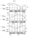
図1に、変調波1周期あたり5個のPWMパルスを含む場合の変調波とPWMキャリアの関係を示す。以下、本発明では、この方式を「HOP(High−efficiency Over−modulation PWM)制御の同期5パルスモード」と呼ぶ。
Next, a specific operation and generation method of the PWM control method of the present invention will be described.
FIG. 1 shows the relationship between a modulated wave and a PWM carrier when 5 PWM pulses are included per modulated wave period. Hereinafter, in the present invention, this method is referred to as “HOP (High-efficiency Over-modulation PWM) control synchronous 5-pulse mode”.
図1(a)のように、変調波1周期に対して9倍の周期となる三角波キャリアを配置する。ここで、三角波キャリアは、U相基本波電圧の位相が0度のときに振幅を0とし、カウントアップしていくものとする。
次に、図1(a)から、本発明のHOP制御における変調波について詳しく説明する。
As shown in FIG. 1A, a triangular wave carrier having a
Next, the modulation wave in the HOP control of the present invention will be described in detail with reference to FIG.
まず、変調波は、基本波電圧指令がゼロクロスする0度と180度を含む位相領域で、位相制御角αを調整することでオンオフ制御を行う。ここでは、三相出力電圧の対称性を考慮し、基本波電圧がゼロクロスする0度の位相と、その0度を中心に+α度と−α度の位相で、オン動作またはオフ動作を行う。また、相電圧の正負対称性を考慮し、基本波電圧がゼロクロスする180度の位相と、その180度を中心に+α度と−α度の位相で、オン動作またはオフ動作を行う。なお、基本波電圧のゼロクロス近傍の位相を含むオンオフ制御は、位相制御角αを用いて行ったが、ゼロクロス近傍を含む位相領域であれば、この位相制御角αを複数個設定し、オンオフ動作を増やしてもよい。 First, the modulated wave is subjected to on / off control by adjusting the phase control angle α in a phase region including 0 degrees and 180 degrees where the fundamental wave voltage command is zero-crossed. Here, in consideration of the symmetry of the three-phase output voltage, the ON operation or the OFF operation is performed with a phase of 0 degree where the fundamental voltage is zero-crossed and a phase of + α degree and −α degree centering on the 0 degree. Further, in consideration of the positive / negative symmetry of the phase voltage, the ON operation or the OFF operation is performed with a phase of 180 degrees where the fundamental voltage is zero-crossed and a phase of + α degrees and −α degrees centering on the 180 degrees. The on / off control including the phase near the zero cross of the fundamental wave voltage was performed using the phase control angle α. However, if the phase region includes the vicinity of the zero cross, a plurality of phase control angles α are set and the on / off operation is performed. May be increased.
次に、基本波電圧の正負ピーク点を含む位相領域において、変調波振幅Amを調整することでPWMパルスのオン、オフ制御を行い、出力するPWMパルス電圧の基本波電圧の大きさを制御する。本発明によるHOP制御の同期5パルスモードでは、三角波キャリアの周波数fcを変調波周波数f1の9倍とし、変調波振幅Amを調整する位相領域が70度から110度、および250度から290度の範囲となる。また、Amの極性は、70度から110度の位相領域と250度から290度の位相領域で反転するように設定する。 Next, in the phase region including the positive and negative peak points of the fundamental wave voltage, on / off control of the PWM pulse is performed by adjusting the modulation wave amplitude Am, and the magnitude of the fundamental wave voltage of the output PWM pulse voltage is controlled. . In the synchronous 5-pulse mode of the HOP control according to the present invention, the frequency fc of the triangular wave carrier is set to 9 times the modulation wave frequency f1, and the phase region for adjusting the modulation wave amplitude Am is 70 degrees to 110 degrees, and 250 degrees to 290 degrees. It becomes a range. In addition, the polarity of Am is set so as to be inverted in a phase region of 70 to 110 degrees and a phase region of 250 to 290 degrees.
図1(b)に、図1(a)の変調波と三角波キャリアとの大小関係から生成される相電圧のPWMパルス電圧波形を示す。図示のように、変調波と三角波キャリアを大小比較することで、変調波1周期あたり5個のパルス電圧が生成されることがわかる。
また、図1(c)に、U相電圧とV相電圧の線間出力電圧波形を示す。
FIG. 1B shows a PWM pulse voltage waveform of the phase voltage generated from the magnitude relationship between the modulated wave and the triangular wave carrier in FIG. As shown in the figure, it is understood that five pulse voltages are generated per period of the modulated wave by comparing the magnitude of the modulated wave and the triangular wave carrier.
FIG. 1C shows the output voltage waveform between the U-phase voltage and the V-phase voltage.
図1(a)のように、70度から110度、および250度から290度の位相領域において変調波振幅Amを直線とした場合、基本波電圧の大きさA1は、位相制御角αと変調波振幅Amを用いて[数3]のように表すことができる。
これより、変調率Ymは、位相制御角αと変調波振幅Amを用いて[数4]のように表すことができる。なお、変調率Ymは、同期1パルス駆動時の出力電圧の大きさを1とする。
したがって、位相制御角αを一定値に固定すると、変調波振幅Amは変調率Ymから一意に求めることができ、[数5]のように表せる。
変調波振幅Amの範囲が−1から1の設定であるため、位相制御角αの設定値によって出力可能な変調率の上限値および下限値が決定する。例えば、位相制御角αを10度とした場合の出力可能な変調率Ymについて、その上限値は0.9696、その下限値は0.2856となる。 Since the range of the modulation wave amplitude Am is set to −1 to 1, the upper limit value and the lower limit value of the modulation rate that can be output are determined by the set value of the phase control angle α. For example, regarding the modulation rate Ym that can be output when the phase control angle α is 10 degrees, the upper limit value is 0.9696, and the lower limit value is 0.2856.
図15に、[数5]に基づいた変調率Ymと変調波振幅Amの関係を示す。この関係に基づいて、変調率Ymに対応する変調波振幅Amを設定することで、変調波1周期中の相電圧のパルス数を一定に保持したまま、所望の交流電圧を出力することができる。また、前述した過変調PWMとは違い、基本波電圧の電気角1周期中のパルス数を減少せずに、最大出力電圧となる同期1パルス駆動の変調率1に近い値まで、基本波電圧を出力することができる。
FIG. 15 shows the relationship between the modulation rate Ym and the modulation wave amplitude Am based on [Equation 5]. Based on this relationship, by setting the modulation wave amplitude Am corresponding to the modulation factor Ym, it is possible to output a desired AC voltage while keeping the number of phase voltage pulses in one period of the modulation wave constant. . Further, unlike the overmodulation PWM described above, the fundamental voltage does not decrease the number of pulses in one period of the electrical angle of the fundamental wave voltage, and reaches a value close to the
図16に、前述した本発明によるHOP制御の5パルスモードにおける3相分の変調波とPWMパルスの関係を示す。
次に、変調波1周期に対して9倍の周期となる三角波キャリアを配置した場合のHOP制御の同期5パルスモードにおいて、変調波振幅Amが−1から1まで変化したときのPWMパルス波形を図17〜19に示す。
FIG. 16 shows the relationship between the modulation wave for three phases and the PWM pulse in the 5-pulse mode of the HOP control according to the present invention described above.
Next, the PWM pulse waveform when the modulation wave amplitude Am changes from −1 to 1 in the synchronous 5-pulse mode of HOP control in the case where a triangular wave carrier having a
図17に、変調波振幅Amが−1の場合のPWMパルス電圧波形を示す。変調波振幅Amが−1の場合、基本波電圧の70度から110度の位相領域はオフ状態で保持され、250度から290度の領域はオン状態で保持される。このとき、変調率Ymは、基本波電圧のゼロクロス近傍の位相領域におけるスイッチング動作の位相制御角αによって決まるPWMパルス電圧波形となる。 FIG. 17 shows a PWM pulse voltage waveform when the modulation wave amplitude Am is −1. When the modulation wave amplitude Am is −1, the phase region of the fundamental voltage from 70 degrees to 110 degrees is held in the off state, and the region of 250 degrees to 290 degrees is held in the on state. At this time, the modulation factor Ym is a PWM pulse voltage waveform determined by the phase control angle α of the switching operation in the phase region near the zero cross of the fundamental voltage.
次に、変調波振幅Amが−1から1の間にある場合、図18(Am=0の場合)のように、基本波出力電圧の正負ピーク点を含む位相領域のオンオフ制御では、変調波振幅Amの大きさに応じたオンオフ制御が行われる。実施例1では、基本波電圧のゼロクロス近傍の位相領域におけるスイッチング動作の位相制御角αを一定値とし、変調波振幅Amを調整するだけで、基本波電圧の出力(変調率Ym)を制御する。 Next, when the modulation wave amplitude Am is between −1 and 1, as shown in FIG. 18 (when Am = 0), in the on / off control of the phase region including the positive and negative peak points of the fundamental wave output voltage, the modulation wave On / off control according to the magnitude of the amplitude Am is performed. In the first embodiment, the output (modulation factor Ym) of the fundamental voltage is controlled simply by setting the phase control angle α of the switching operation in the phase region near the zero cross of the fundamental wave voltage to a constant value and adjusting the modulation wave amplitude Am. .
図19に、変調波振幅Amが1の場合のPWMパルス電圧波形を示す。変調波振幅Amが1の場合、基本波電圧の70度から110度の位相領域はオン状態で保持され、250度から290度の位相領域はオフ状態で保持される。このとき、変調率Ymは、基本波電圧のゼロクロス近傍の位相領域におけるスイッチング動作の位相制御角αによって決まるPWMパルス電圧波形となる。なお、図19では、変調波振幅Amが1のとき、PWMのオンオフ制御は、基本波電圧のゼロクロス近傍の位相領域におけるオン、オフ制御のみが行われることになるため、相電圧パルス数が3となる。 FIG. 19 shows a PWM pulse voltage waveform when the modulation wave amplitude Am is 1. When the modulation wave amplitude Am is 1, the phase region of 70 to 110 degrees of the fundamental voltage is held in the on state, and the phase region of 250 to 290 degrees is held in the off state. At this time, the modulation factor Ym is a PWM pulse voltage waveform determined by the phase control angle α of the switching operation in the phase region near the zero cross of the fundamental voltage. In FIG. 19, when the modulation wave amplitude Am is 1, the PWM on / off control is performed only in the phase region near the zero cross of the fundamental voltage, so the number of phase voltage pulses is 3. It becomes.
本発明の実施例1において、ゼロクロス付近の位相領域におけるスイッチング動作の位相制御角αは所望の出力電圧の大きさに依らず、一定値とした。その結果、ゼロクロス近傍の位相制御角αのオンオフ制御により、出力電圧には上限値と下限値が存在する。これらの上限値や下限値を変えたい場合、位相制御角αの設定値を調整すればよい。また、位相制御角αを調整し、最終的に位相制御角αを0、変調波振幅Amを1とすることで、同期1パルスのPWM電圧波形に連続的に出力波形を変化させることも可能である。 In Example 1 of the present invention, the phase control angle α of the switching operation in the phase region near the zero cross is set to a constant value regardless of the desired output voltage. As a result, the output voltage has an upper limit value and a lower limit value due to the on / off control of the phase control angle α near the zero cross. In order to change these upper limit value and lower limit value, the set value of the phase control angle α may be adjusted. In addition, by adjusting the phase control angle α and finally setting the phase control angle α to 0 and the modulation wave amplitude Am to 1, it is also possible to continuously change the output waveform to a synchronous 1-pulse PWM voltage waveform It is.
また、実施例1の説明において、オンオフ制御を行う領域の変調波を直線として説明したが、正弦波などの任意の曲線で設定してもよく、[数5]や図15のように、変調率Ymと変調波振幅Amの関係が得られれば、それに基づいて所望の電圧を出力することができる。また、オンオフ制御を行う領域の変調波を直線とせずに、正弦波などの任意の曲線で設定した場合には、1相分のスイッチングパルスの幅は一定とはならず変化する。しかし、このような場合であっても、U相−V相間の線間電圧の位相が0〜60の位相領域のパルス波形は、V相のスイッチング波形によって決まり、60〜120の位相領域のパルス波形は、U相のスイッチング波形によって決まるため、線間電圧のパルス波形はピーク点を中心に線対称となり、従来技術よりも交流電流のリップルを抑えることができる。 In the description of the first embodiment, the modulation wave in the region where the on / off control is performed is described as a straight line. However, an arbitrary curve such as a sine wave may be set, and modulation may be performed as in [Equation 5] and FIG. If the relationship between the rate Ym and the modulation wave amplitude Am is obtained, a desired voltage can be output based on the relationship. In addition, when the modulation wave in the region where the on / off control is performed is not a straight line but is set by an arbitrary curve such as a sine wave, the width of the switching pulse for one phase does not become constant. However, even in such a case, the pulse waveform in the phase region in which the phase of the line voltage between the U phase and the V phase is 0 to 60 is determined by the V phase switching waveform, and the pulse in the phase region of 60 to 120 is used. Since the waveform is determined by the switching waveform of the U phase, the pulse waveform of the line voltage is line symmetric with respect to the peak point, and the ripple of the alternating current can be suppressed as compared with the prior art.
また、PWM電圧のパルス数に対して、ベースとなる三角波キャリアの周期は変調波の整数倍であればよい。所望のパルス数に応じて、変調波振幅をAmとしてオンオフ制御する位相領域が変化することになり、[数5]や図15のように、変調率と変調波振幅の関係が得られれば、それに基づいて所望の電圧を出力することができる。 Further, the period of the triangular wave carrier serving as a base with respect to the number of pulses of the PWM voltage may be an integer multiple of the modulation wave. Depending on the desired number of pulses, the phase region for on / off control is changed with the modulation wave amplitude as Am, and if the relationship between the modulation rate and the modulation wave amplitude is obtained as shown in [Equation 5] and FIG. Based on this, a desired voltage can be output.
例えば、図20に、変調波1周期に対して21倍の周期となる三角波キャリアを配置した場合の、HOP制御の相電圧のPWMパルス波形を示す。ここでは、変調波振幅Amを調整する位相領域が81.43度から98.57度、および261.43度から278.57度の範囲とすることで5パルス波形となり、5パルスモードで出力電圧を制御することができる。
For example, FIG. 20 shows a PWM pulse waveform of the phase voltage of the HOP control when a triangular wave carrier having a
一方、図21では、三角波キャリアの周期および配置を図20と同じとし、変調波振幅Amを調整する位相領域を64.29度から115.71度、および244.29度から295.71度の範囲とすることで9パルス波形となり、9パルスモードで出力電圧を制御することができる。 On the other hand, in FIG. 21, the period and arrangement of the triangular wave carriers are the same as in FIG. 20, and the phase region for adjusting the modulation wave amplitude Am is from 64.29 degrees to 115.71 degrees and from 244.29 degrees to 295.71 degrees. By setting the range, a 9-pulse waveform is obtained, and the output voltage can be controlled in the 9-pulse mode.
また、60度から120度の位相領域と240度から300度の位相領域を、変調波振幅Amを調整してオンオフ制御を行う位相領域として説明したが、必ずしも60度から120度と240度から300度の全領域においてスイッチング制御を行う必要はない。基本波電圧の極大値または極小値を含む位相領域でスイッチング制御を行えば、線間電圧のパルス波形は、線間電圧のピーク点を中心とした線対称となるため、従来よりも交流電圧のひずみを抑制するという効果は少なくとも達成することができる。スイッチング制御の領域を当該位相領域の内側(70度から110度および250度から290度の領域)に設定することによっても、本発明の効果は達成可能である。 In addition, the phase range from 60 degrees to 120 degrees and the phase area from 240 degrees to 300 degrees have been described as phase areas in which on / off control is performed by adjusting the modulation wave amplitude Am, but from 60 degrees to 120 degrees and 240 degrees. It is not necessary to perform switching control in the entire region of 300 degrees. If switching control is performed in the phase region including the maximum or minimum value of the fundamental voltage, the pulse waveform of the line voltage becomes line symmetric about the peak point of the line voltage. At least the effect of suppressing strain can be achieved. The effect of the present invention can also be achieved by setting the switching control region inside the phase region (regions of 70 to 110 degrees and 250 to 290 degrees).
図22に、変調波1周期に対して33倍の周期となる三角波キャリアを配置した場合の、HOP制御の9パルスモードのPWM電圧波形を示す。
図22では、変調波振幅Amを調整する位相領域が73.64度から106.36度、および253.64度から286.36度の範囲とすることで9パルス波形となり、9パルスモードで出力電圧を制御することができる。また、図21の9パルスモードと比べて、より基本波電圧の正負ピーク点付近に片寄ってオンオフ制御を実施していることが確認できる。より低次の高調波損失の低減効果が得られる位相領域に、このオンオフ制御の位相領域を限定することで、高調波損失を低減するのに最適な出力電圧のオンオフ制御が実現できる。
FIG. 22 shows a PWM voltage waveform in a 9-pulse mode of HOP control when a triangular wave carrier having a
In FIG. 22, when the phase region for adjusting the modulation wave amplitude Am is in the range of 73.64 degrees to 106.36 degrees and 253.64 degrees to 286.36 degrees, a 9 pulse waveform is obtained and output in the 9 pulse mode. The voltage can be controlled. In addition, it can be confirmed that the on / off control is performed closer to the vicinity of the positive and negative peak points of the fundamental voltage compared to the 9-pulse mode of FIG. By limiting the phase region of the on / off control to a phase region in which a lower harmonic loss reduction effect can be obtained, the output voltage on / off control optimal for reducing the harmonic loss can be realized.
このように、変調波振幅Amを調整する位相範囲と、三角波キャリアの周波数および配置の組合せによって、任意のパルス数のPWM電圧波形を生成することが可能である。これらのPWM波形においても同様に、低次の高調波電圧の増加を抑制し、パルス数を変えずに出力電圧を制御できるため、従来技術よりもモータの高調波損失が低減でき、より高効率駆動が可能なモータ駆動システムが実現できる。
ここで、本発明によるHOP制御の同期7パルスモード、同期9パルスモード、同期11パルスモードのPWM電圧波形を示す。変調波1周期に対して配置する三角波キャリアの周期を変更することで、所望のパルス数とするHOP制御のPWM電圧波形を実現することが可能である。
Thus, a PWM voltage waveform having an arbitrary number of pulses can be generated by a combination of the phase range for adjusting the modulation wave amplitude Am and the frequency and arrangement of the triangular wave carrier. Similarly in these PWM waveforms, it is possible to control the output voltage without changing the number of pulses by suppressing an increase in low-order harmonic voltage, so that the harmonic loss of the motor can be reduced and higher efficiency than the conventional technology. A motor drive system capable of driving can be realized.
Here, PWM voltage waveforms in the synchronous 7-pulse mode, synchronous 9-pulse mode, and synchronous 11-pulse mode of the HOP control according to the present invention are shown. By changing the period of the triangular wave carrier arranged for one period of the modulated wave, it is possible to realize a PWM voltage waveform of HOP control with a desired number of pulses.
図23に、本発明によるHOP制御の同期7パルスモードの電圧波形を示す。図23のように、変調波1周期に対して15倍の周期となる三角波キャリアを配置し、位相制御角αとして基本波電圧のゼロクロス近傍でのオンオフ制御と、変調波振幅Amとして基本波電圧の66度から114度および246度から294度の位相領域でオンオフ制御を行うことで、変調波1周期内に7個のパルス電圧を含むPWM電圧波形を実現できる。なお、変調波振幅Amの極性は、66度から114度の位相領域と246度から294度の位相領域で反転するよう設定する。
FIG. 23 shows voltage waveforms in the synchronous 7-pulse mode of HOP control according to the present invention. As shown in FIG. 23, a triangular wave carrier having a
図23(a)のように、66度から114度、および246度から294度の位相領域において変調波振幅Amを直線とした場合、基本波電圧の大きさA1は、位相制御角αと変調波振幅Amを用いて[数6]のように表すことができる。
これより、変調率Ymは、位相制御角αと変調波振幅Amを用いて[数7]のように表すことができる。なお、変調率Ymは、同期1パルス駆動時の出力電圧の大きさを1とする。
したがって、位相制御角αを一定値に固定すると、変調波振幅Amは変調率Ymから一意に求めることができ、[数8]のように表せる。
図23に示す、本発明によるHOP制御の同期7パルスモードにおいて、変調波振幅Amの範囲が−1から1の設定であるとき、位相制御角αの設定値によって出力可能な変調率の上限値および下限値が決定する。例えば、位相制御角αを7度とした場合の出力可能な変調率Ymについて、その上限値は0.98509、その下限値は0.17162となる。 In the synchronous 7-pulse mode of HOP control according to the present invention shown in FIG. 23, when the range of the modulation wave amplitude Am is set to −1 to 1, the upper limit value of the modulation rate that can be output by the set value of the phase control angle α And the lower limit is determined. For example, regarding the modulation rate Ym that can be output when the phase control angle α is 7 degrees, the upper limit value is 0.98509 and the lower limit value is 0.17162.
図24に、本発明によるHOP制御の同期9パルスモードの電圧波形を示す。ここでは、変調波1周期に対して21倍の周期となる三角波キャリアを配置し、位相制御角αとして基本波電圧のゼロクロス近傍でのオンオフ制御と、変調波振幅Amとして基本波電圧の64.3度から115.7度および244.3度から295.7度の位相領域でオンオフ制御を行うことで、変調波1周期内に9個のパルス電圧を含むPWM電圧波形を実現できる。なお、変調波振幅Amの極性は、64.3度から115.7度の位相領域と244.3度から295.7度の位相領域で反転するように設定する。
FIG. 24 shows voltage waveforms in the synchronous 9-pulse mode of HOP control according to the present invention. Here, a triangular wave carrier having a
図24(a)のように、64.3度から115.7度および244.3度から295.7度の位相領域において変調波振幅Amを直線とした場合、基本波電圧の大きさA1は、位相制御角αと変調波振幅Amを用いて[数9]のように表すことができる。
これより、変調率Ymは、位相制御角αと変調波振幅Amを用いて[数10]のように表すことができる。なお、変調率Ymは、同期1パルス駆動時の出力電圧の大きさを1とする。
したがって、位相制御角αを一定値に固定すると、変調波振幅Amは変調率Ymから一意に求めることができ、[数11]のように表せる。
図24に示す、本発明によるHOP制御の同期9パルスモードにおいて、変調波振幅Amの範囲が−1から1の設定であるとき、位相制御角αの設定値によって出力可能な変調率の上限値および下限値が決定する。例えば、位相制御角αを5度とした場合の出力可能な変調率Ymについて、その上限値は0.9923、その下限値は0.1247となる。 In the synchronous 9-pulse mode of HOP control according to the present invention shown in FIG. 24, when the range of the modulation wave amplitude Am is set to −1 to 1, the upper limit value of the modulation rate that can be output by the set value of the phase control angle α And the lower limit is determined. For example, for the modulation rate Ym that can be output when the phase control angle α is 5 degrees, the upper limit value is 0.9923, and the lower limit value is 0.1247.
図25に、本発明によるHOP制御の同期11パルスモードの電圧波形を示す。ここでは、変調波1周期に対して27倍の周期となる三角波キャリアを配置し、位相制御角αとして基本波電圧のゼロクロス近傍でのオンオフ制御と、変調波振幅Amとして基本波電圧の63.4度から116.7度および243.4度から296.6度の位相領域でオンオフ制御を行うことで、変調波1周期内に11個のパルス電圧を含むPWM電圧波形を実現できる。なお、変調波振幅Amの極性は、63.4度から116.7度の位相領域と243.4度から296.6度の位相領域で反転するよう設定する。
FIG. 25 shows voltage waveforms in the synchronous 11 pulse mode of HOP control according to the present invention. Here, a triangular wave carrier having a
図25(a)のように、63.4度から116.7度および243.4度から296.6度の位相領域において変調波振幅Amを直線とした場合、基本波電圧の大きさA1は、位相制御角αと変調波振幅Amを用いて[数12]のように表すことができる。
これより、変調率Ymは、位相制御角αと変調波振幅Amを用いて[数13]のように表すことができる。なお、変調率Ymは、同期1パルス駆動時の出力電圧の大きさを1とする。
したがって、位相制御角αを一定値に固定すると、変調波振幅Amは変調率Ymから一意に求めることができ、[数14]のように表せる。
図25に示す本発明によるHOP制御の同期11パルスモードにおいて、変調波振幅Amの範囲が−1から1の設定であるとき、位相制御角αの設定値によって出力可能な変調率の上限値および下限値が決定する。例えば、位相制御角αを4度とした場合の出力可能な変調率Ymについて、その上限値は0.9951、その下限値は0.09753となる。 In the synchronous 11 pulse mode of HOP control according to the present invention shown in FIG. 25, when the range of the modulation wave amplitude Am is −1 to 1, the upper limit value of the modulation rate that can be output by the set value of the phase control angle α and The lower limit is determined. For example, regarding the modulation rate Ym that can be output when the phase control angle α is 4 degrees, the upper limit value is 0.9951, and the lower limit value is 0.09753.
同様にして、本発明のHOP制御では、同期13パルスモードのPWM電圧波形を、変調波1周期に対して33倍の周期となる三角波キャリアを配置することにより、また、同期15パルスモードのPWM電圧波形を、変調波1周期に対して39倍の周期となる三角波キャリアを配置することにより、それぞれ実現することもできる。
Similarly, in the HOP control of the present invention, a PWM voltage waveform in the synchronous 13-pulse mode is arranged by arranging a triangular wave carrier having a
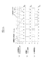
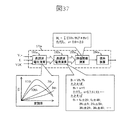
次に、本発明によるPWM電圧波形の高調波含有率の低減効果および高調波電流の低減効果を確認するため、従来技術のPWM電圧波形に含まれる高調波電圧成分と前述した本発明のPWM電圧波形に含まれる高調波電圧および高調波電流をシミュレーションより比較した。
比較に用いる従来技術のPWM電圧波形は、図8に示す同期7パルスモードとし、それと比較する本発明のPWM電圧波形は、従来技術と基本波電圧1周期あたりのパルス数が同じになるように、図23に示すHOP制御の同期7パルスモードとした。
Next, in order to confirm the effect of reducing the harmonic content of the PWM voltage waveform and the effect of reducing the harmonic current according to the present invention, the harmonic voltage component included in the PWM voltage waveform of the prior art and the PWM voltage of the present invention described above are used. The harmonic voltage and harmonic current contained in the waveforms were compared by simulation.
The PWM voltage waveform of the prior art used for the comparison is the synchronous 7 pulse mode shown in FIG. 8, and the PWM voltage waveform of the present invention to be compared with the PWM voltage waveform of the present invention is the same as the prior art so that the number of pulses per cycle of the fundamental wave voltage is the same. The synchronous 7-pulse mode of the HOP control shown in FIG.
また、本発明は、基本波電圧のゼロクロス近傍の位相領域におけるオンオフ制御を特徴の一つとするが、その高調波電圧低減効果を、本発明のHOP制御によるPWM電圧波形からゼロクロス近傍のオンオフ制御を行わない場合の、同期7パルスモードのパルス電圧波形(以下、「効果検証用のPWM制御」と称す)と比較することにより確認する。
なお、高調波電圧の計算において、比較するパルスモードごとで、変調率や基本波電圧の周波数は同一条件とした。
In addition, the present invention is characterized by on / off control in the phase region near the zero cross of the fundamental voltage. The harmonic voltage reduction effect is achieved by controlling on / off near the zero cross from the PWM voltage waveform by the HOP control of the present invention. This is confirmed by comparing with a pulse voltage waveform in the synchronous 7-pulse mode (hereinafter referred to as “PWM control for effect verification”) when not performed.
In the calculation of the harmonic voltage, the modulation rate and the frequency of the fundamental voltage were set to the same condition for each pulse mode to be compared.
図26から図28に、比較のために、高調波電圧の算出に用いたPWM電圧波形をそれぞれ示す。
図26は、従来技術のPWM電圧波形である。
図27は、効果検証用のPWM制御によるPWM電圧波形である。なお、相電圧1周期中のパルス数は、従来技術および本発明のPWM電圧波形と同じにした。
図28は、本発明のHOP制御によるPWM電圧波形である。
26 to 28 show PWM voltage waveforms used for the calculation of the harmonic voltage for comparison.
FIG. 26 shows a conventional PWM voltage waveform.
FIG. 27 shows a PWM voltage waveform by PWM control for effect verification. Note that the number of pulses in one cycle of the phase voltage was the same as that of the PWM voltage waveform of the prior art and the present invention.
FIG. 28 shows a PWM voltage waveform by the HOP control of the present invention.
各パルスモードのPWM電圧の高調波含有率は、相電圧パルス波形を周波数解析し、各高調波電圧の二乗和の平方根と基本波電圧との比較により評価した。高調波電圧の計算では、基本波電圧の周波数に対して5次、7次、11次、13次、17次および19次の各高調波電圧分を対象として計算した。
また、各パルスモードの高調波電流の比較においては、前述の5次、7次、11次、13次、17次および19次の各高調波電圧成分を、それぞれの次数に応じた高調波周波数で割り算した値を用いて、高調波電流の相対評価を行った。
The harmonic content of the PWM voltage in each pulse mode was evaluated by frequency analysis of the phase voltage pulse waveform and comparing the square root of the square sum of each harmonic voltage with the fundamental voltage. In the calculation of the harmonic voltage, calculation was performed for the harmonic voltages of the fifth, seventh, eleventh, thirteenth, seventeenth, and nineteenth harmonics with respect to the frequency of the fundamental voltage.
Further, in the comparison of the harmonic currents of the respective pulse modes, the above-mentioned fifth-order, seventh-order, eleventh-order, thirteenth-order, seventeenth-order and nineteenth-order harmonic voltage components are converted into harmonic frequencies corresponding to the respective orders. Relative evaluation of harmonic current was performed using the value divided by.
図29に、比較結果の表を示す。本発明(図28)のほうが従来技術(図26)に対して、高調波含有率および高調波電流が小さいことがわかる。また、本発明と効果検証用のPWM制御(図27)との比較から、本発明のHOP制御におけるゼロクロス近傍のオンオフ制御により、5次や7次の高調波電圧成分を低減できることがわかる。高調波電流が低減したことで、インバータ駆動時のモータの高調波損失が低減される。
また、高調波電流については、高調波電圧を高調波周波数で割り算した値にほぼ比例するため、5次や7次といった低次の高調波電圧成分を低減する効果は、本発明のHOP制御が最も高い(すなわち、図29の高調波電流相対評価値が最も低い)。
FIG. 29 shows a table of comparison results. It can be seen that the present invention (FIG. 28) has a smaller harmonic content and harmonic current than the prior art (FIG. 26). Further, it can be seen from the comparison between the present invention and the PWM control for effect verification (FIG. 27) that the fifth-order and seventh-order harmonic voltage components can be reduced by the on / off control near the zero cross in the HOP control of the present invention. By reducing the harmonic current, the harmonic loss of the motor when driving the inverter is reduced.
In addition, since the harmonic current is approximately proportional to the value obtained by dividing the harmonic voltage by the harmonic frequency, the effect of reducing the lower order harmonic voltage components such as the fifth order and the seventh order is the effect of the HOP control of the present invention. It is the highest (that is, the harmonic current relative evaluation value in FIG. 29 is the lowest).
以上説明したように、本実施例1によれば、基本波電圧のゼロクロス点を含むその近傍の位相領域でパルス電圧のオン動作とオフ動作をそれぞれ1回以上挿入し、さらに、基本波電圧の正側と負側でのピーク点を含むその付近の位相領域でパルス電圧のオン動作とオフ動作をそれぞれ1回以上挿入し、それ以外の位相領域ではオン状態またはオフ状態を保持するように、インバータのスイッチング素子をオン/オフ制御する。これにより、PWM電圧の歪み率(高調波含有率)および高調波電流を低減し、より高効率なモータ駆動システムを実現できるようになる。 As described above, according to the first embodiment, the pulse voltage on-operation and off-operation are inserted at least once each in the phase region in the vicinity including the zero-cross point of the fundamental wave voltage. Insert the pulse voltage on / off operation at least once each in the phase region including the peak point on the positive side and negative side, and keep the on state or off state in the other phase regions. On / off control of the switching element of the inverter is performed. Thereby, the distortion rate (harmonic content rate) and the harmonic current of the PWM voltage are reduced, and a more efficient motor drive system can be realized.
次に、本発明の実施例2について、図30、図31および図32を用いて説明する。
実施例1では、PWM制御において、PWM電圧波形のオンオフ制御の位相領域を基本波電圧の正負ピーク点付近とゼロクロス付近に限定することで、従来技術のPWM電圧波形よりも高調波電圧の含有率が少ないPWM電圧波形を生成し、より高効率なモータ駆動システムを実現できることを示した。
実施例2では、PWM制御を行う際の電圧パルス数や非同期PWMと同期PWMの切替といったPWMパルスモード信号PsやPWMキャリア周波数fcの決定を、実施例1の駆動周波数と駆動電圧に基づくことに加えてモータの負荷状態を考慮することで、さらに高効率なモータ駆動システムを実現できる手法について説明する。
Next, a second embodiment of the present invention will be described with reference to FIGS. 30, 31, and 32. FIG.
In the first embodiment, in the PWM control, the phase region of the on / off control of the PWM voltage waveform is limited to the vicinity of the positive / negative peak point of the fundamental wave voltage and the vicinity of the zero cross, so that the harmonic voltage content rate is higher than the PWM voltage waveform of the prior art. It has been shown that a PWM voltage waveform with less can be generated and a more efficient motor drive system can be realized.
In the second embodiment, the determination of the PWM pulse mode signal Ps and the PWM carrier frequency fc, such as switching between asynchronous PWM and synchronous PWM, is based on the drive frequency and the drive voltage of the first embodiment. In addition, a method that can realize a more efficient motor drive system by considering the load state of the motor will be described.
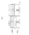
図30は、本発明の実施例2によるモータの駆動システムの構成図である。ここにおいて、部品番号101〜105、111〜115、121〜124、131〜134および141は、実施例1における図2の同じ番号の構成要素と同一である。以下に、図2に示した実施例1と比較して、構成要素の相違部分のみを説明する。
実施例2では、図30に示すように、PWMキャリア決定器116において、PWMモード決定器141の出力を補正するPWMモード補正器142が新たに付加されている。
FIG. 30 is a configuration diagram of a motor drive system according to the second embodiment of the present invention. Here, the
In the second embodiment, as shown in FIG. 30, a
実施例2の特徴部分であるPWMモード補正器142について説明する。PWMモード補正器142は、PWMモード決定器141で決定したPWMパルスモード信号PsやPWMキャリア周波数fcに対して、モータ駆動システムの負荷状態に応じた補正を行う。実施例2では、モータ駆動システムの負荷状態を監視するために、モータ103の相電流を観測している。具体的には、電流検出器121からの交流電流検出値Iu、Iv、Iwおよび電圧指令の一次周波数f1に基づいて、PWMモード決定器141からのPWMパルスモード信号PsやPWMキャリア周波数fcの補正を行っている。
A
図31に、一定周波数で駆動しているモータの負荷と、その時に発生する損失を示す。図31(a)は相電圧のパルス数が9の場合、同図(b)は相電圧のパルス数が3の場合である。損失の内訳を大別すると、インバータに含まれる高調波電圧を起因として発生する高調波損失と、それ以外の損失に分けられる。 FIG. 31 shows a load of a motor driven at a constant frequency and a loss generated at that time. FIG. 31A shows a case where the number of phase voltage pulses is 9, and FIG. 31B shows a case where the number of phase voltage pulses is 3. The breakdown of the loss is roughly divided into a harmonic loss generated due to the harmonic voltage included in the inverter and a loss other than that.
ここで、高調波損失は、モータが誘導電動機の場合には、主に高調波二次銅損が支配的となる。この高調波損失は、駆動周波数、パルス数、ならびに変調率が決まれば、ほぼ、負荷によらずに一定とみなすことができる。これは、誘導機の二次回路に高調波が常に流れ込んでいるためであり、周波数の高い成分に対するすべりがほぼ「1」になることによる。また、パルス数(=PWMパルスモード)と変調率(=出力電圧の基本波の大きさ)が決まれば、出力するPWM電圧波形が決まるため、パルス電圧に含まれる高調波電圧成分も決まることによる。永久磁石モータの場合には、二次銅損は発生しないが、高調波鉄損が大きく存在する。これも負荷によらずにほぼ一定であるとみなすことができる。 Here, when the motor is an induction motor, the harmonic loss is mainly dominant in the harmonic loss. This harmonic loss can be regarded as being constant irrespective of the load if the drive frequency, the number of pulses, and the modulation rate are determined. This is because harmonics are constantly flowing into the secondary circuit of the induction machine, and the slip for a component having a high frequency is almost “1”. Further, if the number of pulses (= PWM pulse mode) and the modulation factor (= the magnitude of the fundamental wave of the output voltage) are determined, the PWM voltage waveform to be output is determined, so that the harmonic voltage component included in the pulse voltage is also determined. . In the case of a permanent magnet motor, there is no secondary copper loss, but there is a large harmonic iron loss. This can also be regarded as almost constant regardless of the load.
また、高調波以外の損失としては、基本波電流による銅損が大きく、これは負荷にほぼ比例すると考えられ、また、インバータの導通損失やスイッチング損失も、負荷にほぼ比例すると考えられる。 Further, as losses other than harmonics, copper loss due to fundamental wave current is large, which is considered to be substantially proportional to the load, and the conduction loss and switching loss of the inverter are also considered to be substantially proportional to the load.
図31の(a)ならび(b)に示すように、9パルスと3パルスでは、それぞれの損失の内訳が異なっている。パルスを増やすことによりモータで発生する高調波損失は低下するが、一方でそれによりスイッチング回数は増えることとなり、インバータで発生するスイッチング損失が増加する。このように、負荷に応じて損失特性が変わってくることになる。したがって、図31(c)に示すように、軽負荷領域では9パルスを、重負荷領域では3パルスを採用することで、発生する損失の最適化が図れることがわかる。 As shown in FIGS. 31 (a) and 31 (b), the breakdown of the loss is different between 9 pulses and 3 pulses. By increasing the pulses, the harmonic loss generated in the motor is reduced, but on the other hand, the number of switching is increased, and the switching loss generated in the inverter is increased. In this way, the loss characteristic changes according to the load. Therefore, as shown in FIG. 31 (c), it is understood that the loss generated can be optimized by adopting 9 pulses in the light load region and 3 pulses in the heavy load region.
このように、軽負荷領域では、モータの高調波損失の低減を重視して、PWM電圧波形のパルス数を増加させ、重負荷領域では、インバータのスイッチング損失の低減を重視して、PWM電圧波形のパルス数を減少させることで、モータ駆動システム全体の高効率化を図ることができる。 In this way, in the light load region, emphasis is placed on reducing the harmonic loss of the motor, and the number of pulses of the PWM voltage waveform is increased. In the heavy load region, emphasis is placed on reducing the switching loss of the inverter, and the PWM voltage waveform. By reducing the number of pulses, it is possible to increase the efficiency of the entire motor drive system.
また、図32には、相電圧のパルス数が1パルス(a)と3パルス(b)の場合の損失を示す。1パルスでは、インバータ3の出力電圧を最大にできるため、同じパワーを出力することを考えると、電流を最も小さくできる。よって、電流を減少させることで銅損が低減でき、重負荷領域における効率が改善する。ただし、1パルス駆動の高調波は非常に大きいため、負荷の軽い条件では、高調波損失が支配的となり、パルス数を3パルスにした方が損失は低減する。
FIG. 32 shows losses when the number of phase voltage pulses is 1 pulse (a) and 3 pulses (b). In one pulse, the output voltage of the
以上説明したように、本実施例2によれば、PWMモード補正器142でモータの相電流の大きさから負荷状態を判定し、予め求めていた負荷状態の切替ポイントに応じてPWMパルスモード信号PsやPWMキャリア周波数fcを変更するように動作する。これによって、負荷状態に応じたモータ駆動システムの運転効率の最大化が実現できる。
As described above, according to the second embodiment, the
次に、本発明の実施例3について、図33および図34を用いて説明する。
実施例2では、PWM制御を行う際のPWMパルスモード信号PsやPWMキャリア周波数fcを、通常は駆動周波数と駆動電圧に基づいて決定しているのに対し、モータの負荷状態を考慮に入れることでより高効率なモータ駆動システムが実現できる手法について示した。
Next,
In the second embodiment, the PWM pulse mode signal Ps and the PWM carrier frequency fc at the time of performing the PWM control are normally determined based on the driving frequency and the driving voltage, but the load state of the motor is taken into consideration. In this paper, a technique that can realize a more efficient motor drive system is shown.
実施例3は、先の実施例2に比べて、さらに、インバータの直流電圧情報を用いて、PWMパルスモード信号PsとPWMキャリア周波数fcを決定する手法について述べる。
図33は、本発明の実施例3のブロック構成図である。ここにおいて、部品番号101〜105、111〜116、121〜124、131〜134および141は、実施例2を示す図30の同じ番号のものと同一であるので、実施例2と比較して構成要素の相違部分のみを説明する。
The third embodiment further describes a method for determining the PWM pulse mode signal Ps and the PWM carrier frequency fc using the DC voltage information of the inverter as compared with the second embodiment.
FIG. 33 is a block diagram of the third embodiment of the present invention. Here, since the
実施例3は、インバータ直流電圧VDCの電圧を検出する電圧センサ135を新たに付加し、その電圧検出値をPWMモード補正器142bに入力している。
PWMモード補正器142bでは、図30におけるPWMモード補正器142とは異なり、インバータの直流電圧値を考慮して、PWMパルスモード信号PsやPWMキャリア周波数fcに補正を加える。
In the third embodiment, a
Unlike the
インバータの直流電圧は、昇圧型(あるいは降圧型)コンバータを用いれば電圧を可変にすることが可能である。インバータの電源となる直流電圧VDCによって、モータの効率は大きく変化する。例えば、電圧を高く設定することで、高速領域まで定トルク駆動が可能となり、モータの駆動電流を低減することができる。ここで、電気鉄道車両用のモータ(主に誘導電動機)を例にとると、高速領域は定出力駆動となり励磁電流を絞った状態での駆動となるため、負荷が大きくなるとトルク電流を大幅に増やす必要があり、効率が劣化する。 The DC voltage of the inverter can be varied by using a step-up (or step-down) converter. The efficiency of the motor varies greatly depending on the DC voltage VDC serving as the power source of the inverter. For example, by setting the voltage high, constant torque drive can be performed up to a high speed region, and the drive current of the motor can be reduced. Here, taking a motor for an electric railway vehicle (mainly an induction motor) as an example, the high-speed region is driven at a constant output and the excitation current is reduced, so the torque current is greatly increased when the load increases. There is a need to increase the efficiency.
しかし、直流電圧を高く設定すると、変調率が下がることにより高調波電流が増加してしまうため、高調波損失は劣化することになる。逆に、低速駆動時に直流電圧を下げることができれば、高調波電流を低減できるため、損失低減に貢献できる。 However, if the DC voltage is set high, the harmonic current increases due to a decrease in the modulation factor, and the harmonic loss is deteriorated. Conversely, if the DC voltage can be lowered during low-speed driving, the harmonic current can be reduced, which can contribute to loss reduction.
図34に、直流電圧VDCを上昇させた場合の損失変化を示す。1パルスと3パルスを比較した場合、直流電圧VDCを増加させることで、1パルス方式の損失がトータルとして低減する。これは、基本波電流の低減によって銅損が改善されたことによる。よって、直流電圧VDCを増加させた場合には、図34の横向き矢印で示すように、パルス数の切替ポイントを軽負荷側にずらす方がトータルの損失が改善する。 FIG. 34 shows a loss change when the DC voltage VDC is increased. When one pulse is compared with three pulses, the loss of the one-pulse method is reduced as a whole by increasing the DC voltage VDC. This is because copper loss has been improved by reducing the fundamental wave current. Therefore, when the DC voltage VDC is increased, the total loss is improved by shifting the switching point of the number of pulses to the light load side as shown by the horizontal arrow in FIG.
以上説明したように、本実施例3によれば、PWMモード補正器142bで、モータの相電流の大きさから負荷状態を判定することに加え、さらにインバータの直流電圧情報を用いて、予め求めていた切替ポイントに応じてPWMパルスモード信号PsやPWMキャリア周波数fcを変更するように動作することにより、さらに運転効率のよいモータ駆動システムが実現できる。
As described above, according to the third embodiment, the
次に、本発明の実施例4について、図35を用いて説明する。
実施例2は、モータの負荷状態に応じて、実施例3は、インバータの直流電圧値を考慮して、PWM制御時のPWMパルスモード信号PsやPWMキャリア周波数fcを変更することでパルス数を増減させ、運転効率の最大化が実現できるシステムである。その中で、PWMパルスモード信号PsやPWMキャリア周波数fcを決定するために、予め計算しておいてデータテーブル等に従うものであることから、テーブルの精度や分解能に依存するものである。
Next, a fourth embodiment of the present invention will be described with reference to FIG.
In the second embodiment, the number of pulses is changed by changing the PWM pulse mode signal Ps and the PWM carrier frequency fc during PWM control in consideration of the DC voltage value of the inverter in accordance with the motor load state. It is a system that can be increased or decreased to achieve maximum operation efficiency. Among them, in order to determine the PWM pulse mode signal Ps and the PWM carrier frequency fc, since it is calculated in advance and follows a data table or the like, it depends on the accuracy and resolution of the table.
実施例4は、実時間において損失計算を実施し、常に最適なパルス数(PWMパルスモードやPWMキャリア周波数)でモータを駆動することを実現する。
図35に、実施例4の特徴部分であるPWMキャリア決定器116cのブロック構成図を示す。
In the fourth embodiment, loss calculation is performed in real time, and the motor is always driven with an optimal number of pulses (PWM pulse mode or PWM carrier frequency).
FIG. 35 is a block diagram of a
図35に示すPWMキャリア決定器116cを、実施例3に係る図33のPWMキャリア決定器116に替えて用いることで、実施例4を実現できることになる。また、PWMモード決定器141は、図2、図30ならびに図33と同じもので構わない。
The fourth embodiment can be realized by using the
図35において、損失演算器151a〜151e(各PWMパルスモード毎に設定)は、システムの状態量から各PWMパルスモードによってPWM制御を実施した時の損失を演算する手段である。具体的に、損失演算器151aは、1パルス時の損失Loss1を演算し出力する。同様に、損失演算器151bは3パルス時、損失演算器151cは9パルス時および損失演算器151dは15パルス時、のそれぞれの損失Loss2、Loss3およびLoss4を演算し出力する。損失演算器151eは、非同期パルス時の損失Loss5を演算し出力する。各損失演算器151a〜151eの各出力は、PWMモード補正器142cに入力される。PWMモード補正器142cでは、これらの損失演算値から最も損失の少ないPWMパルスモードを選択し、それに基づいてキャリア周波数fcを決定する。
In FIG. 35,
また、各損失演算器151a〜151eは、その内部がモータの基本波損失演算器161aおよびモータの高調波損失演算器171aから構成され、常に損失演算を行っている。
基本波損失演算器161aでは、相電流信号Iu〜Iwおよびインバータの直流電圧VDCに基づき、モータの基本波電流に伴う損失を計算している。この基本波電流に伴う損失は、例えば銅損があり、モータの1次抵抗や2次抵抗の値から損失を計算することができる。
Each of the
The fundamental
また、高調波損失演算器171aでは、インバータの直流電圧VDC、駆動周波数f1ならびに電圧指令V1*に基づいて、各PWMパルスモード毎の高調波の損失を演算する。もしくは、モータの相電流信号から高調波電流を抽出し、それにより高調波損失を演算してもよい。これらの基本波および高調波の損失演算を同時に行い、両者を加算器201にて加算することで、各PWMパルスモード毎の全損失を計算している。
The
以上説明したように、本実施例4によれば、モータの駆動状態およびインバータの直流電圧値に応じて、常に異なるパルス数(PWMパルスモードやPWMキャリア周波数)での損失演算が実施できることにより、リアルタイム(実時間)で効率を最大にする駆動が可能になる。よって、モータ駆動システムの高効率化が実現できる。 As described above, according to the fourth embodiment, the loss calculation can always be performed with different number of pulses (PWM pulse mode and PWM carrier frequency) according to the driving state of the motor and the DC voltage value of the inverter. Driving that maximizes efficiency in real time is possible. Therefore, high efficiency of the motor drive system can be realized.
次に、本発明の実施例5について、図36を用いて説明する。
実施例5は、実施例4と同様に実時間において損失計算を実施し、常に最適なパルス数(PWMパルスモードやPWMキャリア周波数)によるモータ駆動を実現するものである。実施例5では、実施例4と比べて、さらにインバータの損失も考慮している点が異なる。
Next,
In the fifth embodiment, the loss calculation is performed in real time in the same manner as the fourth embodiment, and the motor driving is always performed with the optimum number of pulses (PWM pulse mode and PWM carrier frequency). The fifth embodiment is different from the fourth embodiment in that the loss of the inverter is further considered.
図36に、本発明の実施例5の特徴部分であるPWMキャリア決定器116dのブロック構成図を示す。
図36のPWMキャリア決定器116dを、実施例3に係るPWMキャリア決定器116に替えて用いることで実施例5を実現できる。また、PWMモード決定器141は、図2、図30または図33と同じもので構わない。
FIG. 36 shows a block configuration diagram of a PWM
The fifth embodiment can be realized by using the
図36において、損失演算器152aの内部に、インバータ損失演算器181aが付加され、この点が図35の損失演算器151aと異なる点である。インバータの損失は、導通損失とスイッチング損失であることから、モータの相電流信号の大きさおよびインバータの直流電圧VDCの大きさから計算することができる。
In FIG. 36, an
図35と同様に、各損失演算器152a〜152eは、PWMパルスモード毎に常に損失演算をし、各損失演算値であるLoss1〜Loss5を求め、PWMモード補正器142cに入力する。PWMモード補正器142cは、これらの損失演算値から最も損失の少ないPWMパルスモードを選択し、それに基づいてPWMパルスモード信号Psやキャリア周波数fcを決定する。
Similarly to FIG. 35, each of the
以上説明したように、本実施例5によれば、モータの損失にインバータ損失を加えた損失の最小化運転が可能になり、実施例4と比べてさらに高効率なモータ駆動システムが実現できる。また、本実施例5は、実施例4に適用することに限定されるものではなく、実施例3に対して適用することによりインバータ損失に着目してモータ駆動システムの効率化を図ることも可能である。 As described above, according to the fifth embodiment, it is possible to minimize the loss by adding the inverter loss to the motor loss, and it is possible to realize a motor drive system that is more efficient than the fourth embodiment. In addition, the fifth embodiment is not limited to being applied to the fourth embodiment, and by applying to the third embodiment, it is possible to increase the efficiency of the motor drive system by paying attention to the inverter loss. It is.
次に、本発明の実施例6について、図37を用いて説明する。
実施例6は、実施例4または実施例5における高調波損失演算器に係わるものである。
図37に、実施例6の特徴部分である高調波損失演算器173aのブロック構成図を示す。
本発明の実施例6は、図37の高調波損失演算器173aを、実施例4または実施例5である図35または図36の高調波損失演算器171aに替えてそれぞれ用いることで実現できる。
Next,
Example 6 relates to the harmonic loss calculator in Example 4 or Example 5.
FIG. 37 is a block diagram of the
The sixth embodiment of the present invention can be realized by using the
実施例6は、高調波損失の評価関数の導入によって、より高精度に損失の演算が可能になり、さらに高効率なモータ駆動システムを実現するものである。
図37の高調波損失演算器173aは、基本波電圧周波数f1、電圧指令V1*および直流電圧検出値VDCを入力して、高調波電圧成分を計算する高調波電圧演算器191a、この高調波電圧成分から高調波電流成分を演算する高調波電流演算器192a、さらに、この高調波電流成分から評価関数を用いて高調波損失相当を演算する評価関数演算器193aおよびこの高調波損失の評価関数値に基づいて高調波損失を換算する損失換算器194aから構成される。
In the sixth embodiment, by introducing an evaluation function of harmonic loss, loss can be calculated with higher accuracy, and a motor drive system with higher efficiency can be realized.
The
まず、高調波電圧演算器191aでは、PWMパルスモード毎に、変調率Ymに対する各高調波次数の含有率がテーブル化される。例えば、基本波電圧周波数の5倍の周波数成分(第5次成分)は何V含まれるか等、高調波の次数(n次)毎に算出し、基本波電圧周波数に対する高調波の次数(n次)毎の電圧の大きさVhを出力する(図37の左下吹き出し部のグラフ、参照)。また、PWMパルスモードが非同期PWMの場合、変調率Ymに対して高調波電圧PWMキャリアfcの側帯波成分として、高調波周波数fc±2・f1、2・fc±f1などの高調波電圧の含有率がテーブル化されることになる。また、高調波電圧演算器191aは、三相交流電圧指令Vu*、Vv*、Vw*から周波数解析などの演算を行い、高調波電圧成分を算出してもよい。
First, in the
次に、高調波電流演算器192aでは、高調波電圧演算器191aからの高調波電圧Vhを高調波電圧周波数fhまたは高調波の次数nで割り算することで、各高調波成分の電流相当の値Ih(=Vh/fh)を計算する(図37の右下吹き出し部の説明、参照)。ここで、高調波電圧周波数fhや高調波の次数nの代わりに、高調波の周波数とインダクタンス値を用いて各高調波成分の電流値の概算を計算してもよい。また、高調波電流演算器192aは、三相電流検出値Iu、Iv、Iwから周波数解析などの演算を行い、高調波電流成分を算出してもよい。
Next, the harmonic
続いて、評価関数演算器193aでは、高調波電流相当の値Ihから、高調波損失に相関関係のある評価関数を演算する。
ここで演算される評価関数は、モータの高調波損失に相当する量となる。例えば、誘導電動機の二次銅損は、二次抵抗値R2に対して、電流の二乗×R2となるが、高調波電圧の印加による銅損の場合には、回転子の銅バーや一次巻線、または二次巻線の表皮効果の影響で、高調波電圧周波数fhのx乗倍の周波数特性があるといわれている。また、高調波電圧の印加によって渦電流損やヒステリシス損などの鉄損が生じ、その鉄損も高調波電圧周波数fhに依存性を持つことがわかっている。x=0は、二次抵抗に周波数依存性がないことを意味し、回転子構造によってはそのようなケースも有り得る。また、表皮効果が強い場合には、x=0.5〜2.0程度の値を取る。これは、モータの特性に依存するもので、モータが変われば当然指数xの値も変化するところ、実機試験よりx=1前後になることを確認している。
Subsequently, the
The evaluation function calculated here is an amount corresponding to the harmonic loss of the motor. For example, the secondary copper loss of the induction motor is the square of current × R2 with respect to the secondary resistance value R2, but in the case of copper loss due to the application of harmonic voltage, the rotor copper bar or primary winding It is said that there is a frequency characteristic that is x times the harmonic voltage frequency fh due to the skin effect of the wire or the secondary winding. It is also known that iron loss such as eddy current loss and hysteresis loss occurs due to the application of the harmonic voltage, and the iron loss also depends on the harmonic voltage frequency fh. x = 0 means that the secondary resistance has no frequency dependence, and such a case may be present depending on the rotor structure. Further, when the skin effect is strong, x takes a value of about 0.5 to 2.0. This depends on the characteristics of the motor, and if the motor changes, the value of the index x naturally changes. However, it has been confirmed from the actual machine test that x = 1.
図37に示す実施例6は、各高調波電流成分Ih(=Vh/fh)を二乗して、さらに重みとしてその高調波周波数fhのx乗を乗算し、その全成分の加算値を評価関数H1にしている(図37の上部吹き出し部の説明、参照)。この指数xの値と高調波損失の関係を、図38に示す。例えば、x=1.0(すなわち、重みはfhとなる)としたモータの場合には、高調波損失と評価関数が線形になることを確認している。このように、評価関数を導入することで、高調波損失の演算が容易に行えるようになる。 In the sixth embodiment shown in FIG. 37, each harmonic current component Ih (= Vh / fh) is squared, further multiplied by the x power of the harmonic frequency fh as a weight, and the added value of all the components is evaluated function. H1 (refer to the description of the upper blowing portion in FIG. 37). The relationship between the value of the index x and the harmonic loss is shown in FIG. For example, in the case of a motor where x = 1.0 (that is, the weight is fh), it has been confirmed that the harmonic loss and the evaluation function are linear. Thus, by introducing the evaluation function, it is possible to easily calculate the harmonic loss.
最後に、損失換算器194aでは、評価関数H1の値を係数倍することで損失を求めている。この換算係数に関しては、予め一度だけ実測による損失との関係を求めておけばよい。または、FEM(有限要素法)解析などを用いて換算係数を求めることもできる。
Finally, the
以上説明したように、本実施例6によれば、高調波損失の評価関数を導入することによって、より高精度に高調波損失の演算が可能となり、さらに高効率運転が可能なモータ駆動システムが実現できる。 As described above, according to the sixth embodiment, by introducing the harmonic loss evaluation function, it is possible to calculate the harmonic loss with higher accuracy, and to provide a motor drive system capable of high-efficiency operation. realizable.
次に、本発明の実施例7について、図39および図40を用いて説明する。
図39に、実施例7におけるPWMキャリア決定器116eのブロック構成図を示す。
図39に示すPWMキャリア決定器116eを、実施例3に係るPWMキャリア決定器116に替えて用いることで、実施例7を実現できる。
Next, Embodiment 7 of the present invention will be described with reference to FIGS. 39 and 40. FIG.
FIG. 39 is a block diagram of the
The seventh embodiment can be realized by using the
また、実施例7は、実施例4から実施例6における高調波損失演算器に係わるものであり、図39の高調波損失演算器174aを、実施例4から実施例6に係る図35、図36または図37の高調波損失演算器171aや173aに替えてそれぞれ用いることで実現できる。
図39において、損失演算器153aの内部に、高調波損失演算器171aに替えて高調波損失演算器174aが付加されたもので、相電流情報も入力としている点が図35または図36と異なる点である。
In addition, the seventh embodiment relates to the harmonic loss calculator in the fourth to sixth embodiments. The
39 is different from FIG. 35 or FIG. 36 in that a
図40に、本発明の実施例7の特徴部分である高調波損失演算器174aのブロック構成図を示す。ここにおいて、高調波電圧演算器191a、高調波電流演算器192aおよび損失換算器194aは、実施例6に係る図37の同じ番号のものと同一である。
図40に示す高調波損失演算器174aにおいては、電圧指令V1*、基本波電圧周波数f1、直流電圧VDC、三相電流Iu、Iv、Iwおよび各高調波電流成分Ihを入力とする評価関数演算器195aが、図37の評価関数演算器193aに替えて付加されている。
FIG. 40 is a block diagram of the
In the
実施例7では、各高調波電流成分Ih(=Vh/fh)を二乗して、さらに重みとしてその高調波周波数fhのx乗との乗算をし、その全成分の加算値を評価関数H1にしている(図40の上部吹き出し部の説明、参照)。このとき、重みとなる指数xの値は、モータ駆動システムの動作状態に応じて変化させるものとする。例えば、モータ駆動システムの動作状態によって、実施例6で示した指数xの値が、0.5〜2.0の間で変化することを確認している。このように、評価関数の重みをモータ駆動システムの動作状態によって変化させることで、さらに精度良く高調波損失を評価できるようになる。 In the seventh embodiment, each harmonic current component Ih (= Vh / fh) is squared, further multiplied by the x-th power of the harmonic frequency fh as a weight, and the added value of all the components is set as the evaluation function H1. (Refer to the description of the upper blowing portion in FIG. 40). At this time, the value of the index x serving as a weight is changed according to the operating state of the motor drive system. For example, it has been confirmed that the value of the index x shown in the sixth embodiment varies between 0.5 and 2.0 depending on the operating state of the motor drive system. Thus, the harmonic loss can be evaluated with higher accuracy by changing the weight of the evaluation function according to the operating state of the motor drive system.
以上説明したように、本実施例7によれば、高調波損失の評価関数の重みとなる指数xの値を、モータ駆動システムの動作状態に応じて変えることによって、より高精度に損失の演算が可能になり、さらに高効率なモータ駆動システムを実現するものである。 As described above, according to the seventh embodiment, the loss x can be calculated more accurately by changing the value of the index x, which is the weight of the harmonic loss evaluation function, according to the operating state of the motor drive system. Therefore, a more efficient motor drive system can be realized.
次に、本発明の実施例8について、図41を用いて説明する。
図41は、本発明の実施例8のブロック構成図である。実施例8は、実施例3とほぼ同様の構成を示している。ただし、実施例8では、インバータ主回路部132にインバータ温度センサ125aと、モータ103にモータ温度センサ125bが付加され、それらから計測される温度情報を、新たにPWMモード補正器142fの入力として追加している。それ以外の部品は、図33に示す実施例3の構成要素と同じである。
Next, an eighth embodiment of the present invention will be described with reference to FIG.
FIG. 41 is a block diagram of the eighth embodiment of the present invention. The eighth embodiment has a configuration substantially similar to that of the third embodiment. However, in the eighth embodiment, an
PWMモード補正器142fは、モータの負荷状態に応じて損失演算を行い、最も損失の少ないPWMパルスモード信号PsおよびPWMキャリア周波数fcで運転を行う。その際、インバータ損失はインバータの素子温度によって変化し、また、モータの損失(特に、基本波損失)は、モータの温度によって変化することが知られている。そこで、インバータならびにモータに、それぞれ温度センサ125a、125bを取り付け、それぞれの温度状態による換算補正を行った上で損失演算を行えば、より高精度な損失演算が実現できる。例えば、インバータ損失演算では、温度上昇に伴い導通損失は低下し、また、モータの基本波損失では、温度上昇に伴い銅損が増加することになる。このような補正を加えることで、より高精度な損失演算が可能になる。
The
なお、温度による補正は、インバータおよびモータの両方で必ずしも行う必要はなく、どちらか一方だけでも効果は期待できる。また、直接温度を計測せずに、電流の変化やインバータを使って抵抗値を測定し、間接的に温度変化を読み取ることも可能である。 Note that the correction based on the temperature is not necessarily performed in both the inverter and the motor, and the effect can be expected with only one of them. Further, instead of directly measuring the temperature, it is also possible to measure a resistance value using a change in current or an inverter and indirectly read the temperature change.
次に、本発明の実施例9について、図42、図43および図44を用いて説明する。
図42は、本発明の実施例9のブロック構成図である。実施例9は、図2に示す実施例1の構成要素に加えて、HOPゼロクロスSW(スイッチング)パターン決定器143gを新たに付加した構成であり、PWM制御器115に対して、PWMパルスモード信号PsとPWMキャリア周波数fcに加えて新たにHOP制御のゼロクロス付近のオンオフ制御のパターン(位相制御角α)が入力される。
Next, a ninth embodiment of the present invention will be described with reference to FIGS. 42, 43 and 44. FIG.
FIG. 42 is a block diagram of the ninth embodiment of the present invention. In the ninth embodiment, a HOP zero-cross SW (switching)
また、このHOPゼロクロスSW(スイッチング)パターン決定器143gを、実施例2から実施例8に対して新たに付加し、PWMパルスモード信号Ps、PWMキャリア周波数fcおよびHOP制御のゼロクロス付近のオンオフ制御のパターン(位相制御角α)をPWM制御器115の入力とすることによっても、実施例9を実現できる。
Further, this HOP zero cross SW (switching)
HOPゼロクロスSW(スイッチング)パターン決定器143gは、電圧振幅指令V1*、基本波電圧周波数f1およびPWMキャリア決定器116の出力であるPWMパルスモード信号Psに応じて、本発明のHOP制御におけるゼロクロス付近のオンオフ制御のパターン(位相制御角α)を決定する。
The HOP zero cross SW (switching)
また、図42では、HOPゼロクロスSW(スイッチング)パターン決定器143gの出力を位相制御角αとしている。ここで、ゼロクロス付近のオンオフ制御の位相制御角が複数個ある場合には、位相制御角α1、α2、α3、・・・αn(nは正の整数)といった具合に増えることになるが、以下の説明では省略する。
In FIG. 42, the output of the HOP zero-cross SW (switching)
図43に、図24に示す本発明によるHOP制御の同期9パルスモードを例にして、ゼロクロス付近のオンオフ制御の位相制御角αの値を変更したときの、基本波電圧周波数f1または変調率Ymとモータ103で発生する高調波損失との関係を示す。図43の縦軸の高調波損失は、基本波電圧周波数が60Hzで同期1パルス駆動時のモータ高調波損失の大きさを基準に、各HOP制御のパルスモード駆動時の高調波損失を正規化した。図43から、ゼロクロス付近のオンオフ制御の位相制御角αの設定値を変更すると、この位相制御角αに応じてモータの高調波損失を最小化する最適値が存在することがわかる。また、位相制御角αの設定値によって、変調率Ym(=出力電圧)の上限値が異なることがわかる。実際には、変調率Ymだけでなく、基本波電圧周波数f1によっても位相制御角αの最適値が変化することを実験により確認している。
このように、本発明のHOP制御によって、PWMパルスモード毎にゼロクロス付近のオンオフ制御のパターンを、電圧振幅指令V1*および基本波電圧周波数f1に応じて、最適にオンオフ制御を行うことで、モータ駆動システムの高効率化が図れることがわかる。
FIG. 43 shows the fundamental voltage frequency f1 or the modulation factor Ym when the value of the phase control angle α of the on / off control near the zero crossing is changed, taking the synchronous 9-pulse mode of the HOP control according to the present invention shown in FIG. And the harmonic loss generated in the
As described above, the HOP control of the present invention optimally controls the on / off control pattern near the zero cross for each PWM pulse mode according to the voltage amplitude command V1 * and the fundamental voltage frequency f1, so that the motor It can be seen that the drive system can be highly efficient.
また、図44に、本発明によるHOP制御の同期9パルスモードにおいて、さらに変調率Ymを下げていったときの基本波電圧周波数f1または変調率Ymとモータ103で発生する高調波損失との関係を示す。図43に示すように、変調率Ymが1に近い領域では、位相制御角α=6.43度におけるHOP制御の同期9パルスモードのPWM電圧波形が、最も高調波損失が少ない結果であった。しかし、図44によると、変調率Ymを下げていくと、ある変調率Ymから高調波損失の大小関係が逆転し、位相制御角α=5.36度が最も高調波損失が少なくなる。さらに変調率Ymを下げていくと、位相制御角α=4.29度が最も高調波損失が少ないPWM電圧波形となっていることがわかる。
よって、電圧振幅指令V1*および基本波電圧周波数f1に応じて、オンオフ制御の位相制御角αを変更させていくことで、高調波損失が最小となるPWM制御が実現でき、モータ103の運転効率がさらに改善されることになる。
FIG. 44 shows the relationship between the fundamental wave voltage frequency f1 or the modulation factor Ym and the harmonic loss generated in the
Therefore, by changing the phase control angle α of the on / off control according to the voltage amplitude command V1 * and the fundamental wave voltage frequency f1, PWM control that minimizes harmonic loss can be realized, and the operating efficiency of the
以上説明したように、本実施例9によれば、本発明のHOP制御によるゼロクロス付近のオンオフ制御の位相制御角αを、HOPゼロクロスSW(スイッチング)パターン決定器143gにて、予め設定しておいたマップに従い変更することで、さらに高効率なモータ駆動システムが実現できる。
As described above, according to the ninth embodiment, the phase control angle α of the on / off control near the zero cross by the HOP control of the present invention is set in advance by the HOP zero cross SW (switching)
次に、本発明の実施例10について、図45を用いて説明する。
本発明によるモータ駆動システムを用いた電気鉄道車両のモデルを図45に示す。
電気鉄道車両では、モータの容量が100kW以上と大きく、かつ、キャリア周波数を高く設定できないため、高速領域では数パルスによる同期PWM方式が用いられる。その上で、省エネ駆動を実現する必要があるため、本発明によるモータ駆動システムは極めて効果的である。
Next, Example 10 of the present invention will be described with reference to FIG.
FIG. 45 shows a model of an electric railway vehicle using the motor drive system according to the present invention.
In electric railway vehicles, the capacity of the motor is as large as 100 kW or more and the carrier frequency cannot be set high. Therefore, a synchronous PWM method using several pulses is used in the high speed region. In addition, since it is necessary to realize energy-saving drive, the motor drive system according to the present invention is extremely effective.
図45は、先の実施例1から実施例9のいずれかを搭載し、モータとして誘導電動機103a〜103dを駆動する電気鉄道車両システムである。本発明を適用することで、システムの損失を最小に抑えながら駆動運転が可能な電気鉄道車両システムが実現できるようになる。
FIG. 45 shows an electric railway vehicle system that is mounted with any of the first to ninth embodiments and drives the
以上、本発明に係る実施例1から実施例10について説明した。説明上、モータとしては主として誘導電動機を例に説明したが、モータであれば他の電動機であっても同様に適用することが可能である。例えば、永久磁石同期電動機、巻線型同期電動機、リラクタンストルクによる同期機も同様である。また、発電機の制御に対しても同様に適用可能である。 The first to tenth embodiments according to the present invention have been described above. In the description, an induction motor has been mainly described as an example of a motor, but other motors can be similarly applied as long as it is a motor. For example, the same applies to a permanent magnet synchronous motor, a wound synchronous motor, and a synchronous machine using reluctance torque. Further, the present invention can be similarly applied to generator control.
101・・・制御器
102・・・インバータ
103(103a〜103d)・・・モータ
104・・・負荷器
105・・・トルク指令発生器
111・・・ベクトル制御器
112・・・極座標変換器
113・・・三相座標変換器
114・・・位相演算部
115・・・PWM制御器
116・・・PWMキャリア決定器
121・・・電流検出部
122・・・回転速度検出器
131・・・コンデンサ
132・・・インバータ主回路部
133・・・ゲート・ドライバ
134・・・直流抵抗器
135・・・電圧センサ
141・・・PWMモード決定器
142・・・PWMモード補正器
DESCRIPTION OF
Claims (15)
前記ゲート信号により制御されるインバータと、
前記インバータにより駆動されるモータと
を備え、
前記PWM信号制御部は、
前記三相各相において、前記電圧指令信号に基づく基本波電圧指令のゼロクロス点を含む該ゼロクロス点近傍である第1の位相領域では前記ゲート信号のオン動作とオフ動作をそれぞれ1回以上挿入し、かつ前記基本波電圧指令の正負ピーク点を含む該正負ピーク付近である第2の位相領域では前記ゲート信号のオン動作とオフ動作をそれぞれ1回以上挿入し、かつ前記第1および前記第2の各位相領域以外の位相領域では前記ゲート信号をオン状態またはオフ状態に保持し、
前記第1および前記第2の各位相領域の少なくともいずれかにおいて、前記ゲート信号のオンオフ制御を行うことで所望の出力電圧に制御する
ことを特徴とするモータ駆動システム。 A PWM signal control unit that generates a gate signal that is pulse-width modulated from the voltage command signal of each of the three phases;
An inverter controlled by the gate signal;
A motor driven by the inverter,
The PWM signal controller is
In each of the three phases, the gate signal is turned on and off one or more times in the first phase region in the vicinity of the zero cross point including the zero cross point of the fundamental voltage command based on the voltage command signal. In the second phase region that is in the vicinity of the positive / negative peak including the positive / negative peak point of the fundamental voltage command, the gate signal ON operation and the OFF operation are respectively inserted once or more, and the first and second In the phase region other than each phase region, the gate signal is held in an on state or an off state,
In at least one of said first and said second respective phase regions, a motor drive system and controls the desired output voltage by performing a ON OFF control of the gate signal.
前記PWM信号制御部は、前記基本波電圧指令に基づく変調波信号とキャリア信号との比較により前記ゲート信号を生成する際に、前記キャリア信号の周波数および前記第2の位相領域の前記変調波信号の振幅値をそれぞれ制御することにより生成する前記ゲート信号のパルス数を変更する
ことを特徴とするモータ駆動システム。 The motor drive system according to claim 1,
When the PWM signal control unit generates the gate signal by comparing a modulated wave signal based on the fundamental voltage command and a carrier signal, the frequency of the carrier signal and the modulated wave signal in the second phase region A motor drive system characterized by changing the number of pulses of the gate signal generated by controlling the amplitude value of each.
前記第1の位相領域は、前記ゼロクロス点から電気角で±15度以内にする
ことを特徴とするモータ駆動システム。 The motor drive system according to claim 1 or 2,
The motor drive system according to claim 1, wherein the first phase region is within ± 15 degrees in electrical angle from the zero cross point.
前記第2の位相領域は、前記正負ピーク点各々から電気角で±30度以内にする
ことを特徴とするモータ駆動システム。 In the motor drive system according to any one of claims 1 to 3,
The motor drive system according to claim 2, wherein the second phase region is within ± 30 degrees in electrical angle from each of the positive and negative peak points.
前記ゲート信号により制御されるインバータと、
前記インバータにより駆動されるモータと
を備え、
前記PWM信号制御部は、
前記三相各相において、前記電圧指令信号に基づく基本波電圧指令のゼロクロス点を含む該ゼロクロス点近傍である第1の位相領域では前記ゲート信号のオン動作とオフ動作をそれぞれ1回以上挿入し、かつ前記基本波電圧指令の正負ピーク点を含む該正負ピーク付近である第2の位相領域では前記ゲート信号のオン動作とオフ動作をそれぞれ1回以上挿入し、かつ前記第1および前記第2の各位相領域以外の位相領域では前記ゲート信号をオン状態またはオフ状態に保持し、
前記第1および前記第2の各位相領域の少なくともいずれかにおいて、前記ゲート信号のオンオフ制御を行うことで所望の出力電圧に制御し、
前記モータの相電流検出値に従って前記モータの負荷状態を判別し、該負荷状態に基づいて前記ゲート信号のパルス数を決定する
ことを特徴とするモータ駆動システム。 A PWM signal control unit that generates a gate signal that is pulse-width modulated from the voltage command signal of each of the three phases;
An inverter controlled by the gate signal;
A motor driven by the inverter,
The PWM signal controller is
In each of the three phases, the gate signal is turned on and off one or more times in the first phase region in the vicinity of the zero cross point including the zero cross point of the fundamental voltage command based on the voltage command signal. In the second phase region that is in the vicinity of the positive / negative peak including the positive / negative peak point of the fundamental voltage command, the gate signal ON operation and the OFF operation are respectively inserted once or more, and the first and second In the phase region other than each phase region, the gate signal is held in an on state or an off state,
In at least one of said first and said second respective phase regions, is controlled to a desired output voltage by performing a ON OFF control of the gate signal,
A motor drive system characterized by discriminating a load state of the motor according to a detected phase current value of the motor and determining the number of pulses of the gate signal based on the load state.
前記PWM信号制御部は、前記モータの負荷状態と前記インバータの直流電圧検出値とに基づいて、前記ゲート信号のパルス数を決定する
ことを特徴とするモータ駆動システム。 In the motor drive system according to claim 5,
The PWM signal control unit determines the number of pulses of the gate signal based on a load state of the motor and a DC voltage detection value of the inverter.
前記モータの温度測定手段および前記インバータの温度測定手段の少なくともいずれかを備え、
前記PWM信号制御部は、前記モータの温度測定手段からの温度信号および前記インバータの温度測定手段からの温度信号の少なくともいずれかの温度信号を、前記ゲート信号のパルス数を決定する際の補正信号とする
ことを特徴とするモータ駆動システム。 The motor drive system according to claim 6, wherein
Comprising at least one of temperature measuring means for the motor and temperature measuring means for the inverter;
The PWM signal control unit is a correction signal for determining the number of pulses of the gate signal from the temperature signal from the temperature measurement unit of the motor and the temperature signal from the temperature measurement unit of the inverter. A motor drive system characterized by that.
前記モータで発生する損失を演算するモータ損失演算手段および前記インバータで発生する損失を演算するインバータ損失演算手段の少なくともいずれかを備え、
前記PWM信号制御部は、前記モータ損失演算手段からのモータ損失演算信号および前記インバータ損失演算手段からのインバータ損失演算信号の少なくともいずれかを、前記ゲート信号のパルス数を決定する際の補正信号とする
ことを特徴とするモータ駆動システム。 The motor drive system according to claim 6, wherein
Comprising at least one of motor loss calculating means for calculating loss generated in the motor and inverter loss calculating means for calculating loss generated in the inverter;
The PWM signal control unit uses at least one of a motor loss calculation signal from the motor loss calculation means and an inverter loss calculation signal from the inverter loss calculation means as a correction signal for determining the number of pulses of the gate signal. A motor drive system characterized by:
前記モータ損失演算手段は、前記モータの駆動電流の基本波成分による損失および前記インバータで発生する高調波電流による損失を演算し、
前記高調波電流による損失は、前記高調波電流の少なくとも1つ以上の高調波成分それぞれについて、該高調波成分それぞれの電流値をIh、該高調波成分それぞれの周波数をf、該周波数fに伴う前記損失に関する周波数特性を示す指数をxとして、該それぞれのIhの二乗値に該それぞれのfのx乗値を乗算した乗算値Ih2・fxを算出し、当該それぞれの乗算値を総和した結果に基づいて演算される
ことを特徴とするモータ駆動システム。 The motor drive system according to claim 8, wherein
The motor loss calculating means calculates a loss due to a fundamental wave component of the driving current of the motor and a loss due to a harmonic current generated in the inverter,
The loss due to the harmonic current is associated with Ih for the current value of each of the harmonic components, f for the frequency of each of the harmonic components, and f for each of at least one harmonic component of the harmonic current. the index indicating the frequency characteristics related to the loss as x, the respective said x squared value of each f the square value of Ih to calculate a multiplication value Ih 2 · f x obtained by multiplying and summing the respective multiplier A motor drive system that is calculated based on the result.
前記指数xは、前記モータの特性によって0〜2の範囲で変化する
ことを特徴とするモータ駆動システム。 The motor drive system according to claim 9, wherein
The motor drive system according to claim 1, wherein the index x varies in a range of 0 to 2 depending on characteristics of the motor.
前記指数xを、前記モータの動作状態に応じて変化させる
ことを特徴とするモータ駆動システム。 The motor drive system according to claim 10, wherein
The motor drive system, wherein the index x is changed according to an operating state of the motor.
前記モータ損失演算手段は、前記高調波電流の高調波成分Ihを、前記三相各相の電圧指令信号から演算した高調波電圧成分Vhを該高調波電圧成分Vhの周波数fで除算したVh/fにより演算する
ことを特徴とするモータ駆動システム。 The motor drive system according to claim 9, wherein
The motor loss calculation means is configured to divide the harmonic component Ih of the harmonic current from the harmonic voltage component Vh calculated from the voltage command signal of each of the three phases by the frequency f of the harmonic voltage component Vh / Vh / A motor drive system characterized by calculating by f.
前記モータ損失演算手段は、前記高調波電流の高調波成分Ihを、前記モータの相電流検出値の少なくとも1相以上の検出値から演算する
ことを特徴とするモータ駆動システム。 The motor drive system according to claim 9, wherein
The motor loss calculation means calculates a harmonic component Ih of the harmonic current from a detection value of at least one phase of the phase current detection value of the motor.
前記ゲート信号により制御されるインバータと、
前記インバータにより駆動されるモータと
を備え、
前記PWM信号制御部は、
前記三相各相において、前記電圧指令信号に基づく基本波電圧指令のゼロクロス点を含む該ゼロクロス点近傍である第1の位相領域では前記ゲート信号のオン動作とオフ動作をそれぞれ1回以上挿入し、かつ前記基本波電圧指令の正負ピーク点を含む該正負ピーク付近である第2の位相領域では前記ゲート信号のオン動作とオフ動作をそれぞれ1回以上挿入し、かつ前記第1および前記第2の各位相領域以外の位相領域では前記ゲート信号をオン状態またはオフ状態に保持し、
前記第1および前記第2の各位相領域の少なくともいずれかにおいて、前記ゲート信号のオンオフ制御を行うことで所望の出力電圧に制御し、
前記電圧指令信号、前記基本波電圧指令の周波数および前記ゲート信号のパルス数による駆動モードに基づいて、前記第1の位相領域で前記ゲート信号の位相制御角の大きさを制御する
ことを特徴とするモータ駆動システム。 A PWM signal control unit that generates a gate signal that is pulse-width modulated from the voltage command signal of each of the three phases;
An inverter controlled by the gate signal;
A motor driven by the inverter,
The PWM signal controller is
In each of the three phases, the gate signal is turned on and off one or more times in the first phase region in the vicinity of the zero cross point including the zero cross point of the fundamental voltage command based on the voltage command signal. In the second phase region that is in the vicinity of the positive / negative peak including the positive / negative peak point of the fundamental voltage command, the gate signal ON operation and the OFF operation are respectively inserted once or more, and the first and second In the phase region other than each phase region, the gate signal is held in an on state or an off state,
In at least one of said first and said second respective phase regions, is controlled to a desired output voltage by performing a ON OFF control of the gate signal,
Controlling the magnitude of the phase control angle of the gate signal in the first phase region based on a drive mode based on the frequency of the voltage command signal, the frequency of the fundamental voltage command, and the number of pulses of the gate signal. Motor drive system.
Priority Applications (1)
| Application Number | Priority Date | Filing Date | Title |
|---|---|---|---|
| JP2013186143A JP6204121B2 (en) | 2013-09-09 | 2013-09-09 | Motor drive system and electric railway vehicle equipped with the system |
Applications Claiming Priority (1)
| Application Number | Priority Date | Filing Date | Title |
|---|---|---|---|
| JP2013186143A JP6204121B2 (en) | 2013-09-09 | 2013-09-09 | Motor drive system and electric railway vehicle equipped with the system |
Publications (3)
| Publication Number | Publication Date |
|---|---|
| JP2015053824A JP2015053824A (en) | 2015-03-19 |
| JP2015053824A5 JP2015053824A5 (en) | 2016-03-31 |
| JP6204121B2 true JP6204121B2 (en) | 2017-09-27 |
Family
ID=52702446
Family Applications (1)
| Application Number | Title | Priority Date | Filing Date |
|---|---|---|---|
| JP2013186143A Active JP6204121B2 (en) | 2013-09-09 | 2013-09-09 | Motor drive system and electric railway vehicle equipped with the system |
Country Status (1)
| Country | Link |
|---|---|
| JP (1) | JP6204121B2 (en) |
Cited By (2)
| Publication number | Priority date | Publication date | Assignee | Title |
|---|---|---|---|---|
| CN108476011A (en) * | 2016-03-15 | 2018-08-31 | 株式会社日立产机系统 | The control device and drive system of motor |
| CN110719043A (en) * | 2019-11-21 | 2020-01-21 | 深圳国能电气有限公司 | Inverter harmonic compensation method and control device thereof |
Families Citing this family (19)
| Publication number | Priority date | Publication date | Assignee | Title |
|---|---|---|---|---|
| JP6581373B2 (en) * | 2015-03-24 | 2019-09-25 | 株式会社日立産機システム | Motor control device |
| JP6516863B2 (en) * | 2015-11-04 | 2019-05-22 | 三菱電機株式会社 | Motor control device, vacuum cleaner and hand dryer |
| JP6439745B2 (en) | 2016-04-28 | 2018-12-19 | トヨタ自動車株式会社 | Automobile |
| JP6668933B2 (en) * | 2016-05-12 | 2020-03-18 | トヨタ自動車株式会社 | Car |
| WO2018025344A1 (en) * | 2016-08-03 | 2018-02-08 | 三菱電機株式会社 | Electric vacuum cleaner |
| WO2018037454A1 (en) * | 2016-08-22 | 2018-03-01 | 三菱電機株式会社 | Motor drive device, heat pump device, and refrigeration and air-conditioning device |
| WO2018061433A1 (en) | 2016-09-29 | 2018-04-05 | 富士電機株式会社 | Inverter control method, control device, and inverter |
| JP6500872B2 (en) | 2016-10-19 | 2019-04-17 | トヨタ自動車株式会社 | Drive and car |
| JP6439771B2 (en) | 2016-10-19 | 2018-12-19 | トヨタ自動車株式会社 | Driving device and automobile |
| CN106685312B (en) * | 2016-12-02 | 2022-12-16 | 许昌学院 | Power driving protection device with negative temperature compensation |
| JP6741904B2 (en) | 2016-12-09 | 2020-08-19 | 株式会社デンソー | Drive and car |
| JP2018107996A (en) | 2016-12-28 | 2018-07-05 | ルネサスエレクトロニクス株式会社 | Semiconductor device and power conversion device |
| US10978983B2 (en) | 2017-03-29 | 2021-04-13 | Aisin Aw Co., Ltd. | Rotary electric machine control device |
| JP6939693B2 (en) * | 2018-04-27 | 2021-09-22 | 株式会社豊田自動織機 | Pulse pattern generator |
| CN108736787B (en) * | 2018-05-30 | 2019-11-05 | 中车青岛四方车辆研究所有限公司 | Permanent-magnet synchronous traction drive control system and method |
| JP6921273B1 (en) * | 2020-04-17 | 2021-08-18 | 三菱電機株式会社 | Rotating machine control device |
| JP7312205B2 (en) * | 2021-02-22 | 2023-07-20 | 株式会社京三製作所 | Broadband RF power supply and control method |
| JP7291167B2 (en) * | 2021-03-09 | 2023-06-14 | 株式会社京三製作所 | RF band power supply and pulse width modulation control method |
| CN113708701A (en) * | 2021-09-01 | 2021-11-26 | 臻驱科技(上海)有限公司 | Over-modulation method and system of motor controller |
Family Cites Families (6)
| Publication number | Priority date | Publication date | Assignee | Title |
|---|---|---|---|---|
| JPS5839201A (en) * | 1981-08-31 | 1983-03-07 | Toyo Electric Mfg Co Ltd | Control device for electric vehicle |
| JPS62239868A (en) * | 1986-04-09 | 1987-10-20 | Fuji Electric Co Ltd | Control system for voltage-type pwm inverter |
| JP3755089B2 (en) * | 1993-12-17 | 2006-03-15 | 株式会社日立製作所 | Electric vehicle control device |
| JP5558752B2 (en) * | 2009-07-30 | 2014-07-23 | 日立オートモティブシステムズ株式会社 | Power converter |
| US8339077B2 (en) * | 2009-10-08 | 2012-12-25 | Microchip Technology Incorporated | Slow speed operation of brushless direct current motors by gating pulse width modulation drive |
| JP2012023885A (en) * | 2010-07-15 | 2012-02-02 | Toyota Motor Corp | Control device and control method of ac motor |
-
2013
- 2013-09-09 JP JP2013186143A patent/JP6204121B2/en active Active
Cited By (4)
| Publication number | Priority date | Publication date | Assignee | Title |
|---|---|---|---|---|
| CN108476011A (en) * | 2016-03-15 | 2018-08-31 | 株式会社日立产机系统 | The control device and drive system of motor |
| CN108476011B (en) * | 2016-03-15 | 2021-05-28 | 株式会社日立产机系统 | Motor control device and drive system |
| CN110719043A (en) * | 2019-11-21 | 2020-01-21 | 深圳国能电气有限公司 | Inverter harmonic compensation method and control device thereof |
| CN110719043B (en) * | 2019-11-21 | 2021-02-05 | 深圳国能电气有限公司 | Inverter harmonic compensation method and control device thereof |
Also Published As
| Publication number | Publication date |
|---|---|
| JP2015053824A (en) | 2015-03-19 |
Similar Documents
| Publication | Publication Date | Title |
|---|---|---|
| JP6204121B2 (en) | Motor drive system and electric railway vehicle equipped with the system | |
| JP4379427B2 (en) | Control device for multiphase rotating electrical machine | |
| JP4582168B2 (en) | Rotating machine control device and rotating machine control system | |
| JP5471259B2 (en) | Control device | |
| JP4433099B1 (en) | Power converter | |
| US8232753B2 (en) | Control device for electric motor drive apparatus | |
| JP5866065B2 (en) | AC motor control device | |
| WO2011135696A1 (en) | Power conversion device | |
| JP5551833B2 (en) | Power conversion control device, power conversion control method, electric motor, and vehicle drive system | |
| WO2011135694A1 (en) | Power conversion device | |
| JP5757304B2 (en) | AC motor control device | |
| US10879816B2 (en) | Inverter control device | |
| JPWO2019008676A1 (en) | Inverter device and electric power steering device | |
| JP6078282B2 (en) | AC motor drive system and motor vehicle | |
| JPWO2018131093A1 (en) | Motor control device | |
| JP5439352B2 (en) | Power converter | |
| JP2004304868A (en) | Motor controller | |
| EP2713501A2 (en) | PWM control method and driving system of AC motor | |
| WO2021145029A1 (en) | Rotating electrical machine control device | |
| JP6372448B2 (en) | Rotating machine control device | |
| JP3939481B2 (en) | AC motor control device | |
| JP2009131024A (en) | Power conversion apparatus and its control method | |
| JP5717902B2 (en) | Power conversion control device, electric motor, and vehicle drive system | |
| JP7067522B2 (en) | Inverter device | |
| US20240088816A1 (en) | Rotating electrical machine control device |
Legal Events
| Date | Code | Title | Description |
|---|---|---|---|
| A521 | Written amendment |
Free format text: JAPANESE INTERMEDIATE CODE: A523 Effective date: 20160208 |
|
| A621 | Written request for application examination |
Free format text: JAPANESE INTERMEDIATE CODE: A621 Effective date: 20160208 |
|
| A977 | Report on retrieval |
Free format text: JAPANESE INTERMEDIATE CODE: A971007 Effective date: 20161031 |
|
| A131 | Notification of reasons for refusal |
Free format text: JAPANESE INTERMEDIATE CODE: A131 Effective date: 20161108 |
|
| A521 | Written amendment |
Free format text: JAPANESE INTERMEDIATE CODE: A523 Effective date: 20170110 |
|
| A131 | Notification of reasons for refusal |
Free format text: JAPANESE INTERMEDIATE CODE: A131 Effective date: 20170314 |
|
| A521 | Written amendment |
Free format text: JAPANESE INTERMEDIATE CODE: A523 Effective date: 20170316 |
|
| TRDD | Decision of grant or rejection written | ||
| A01 | Written decision to grant a patent or to grant a registration (utility model) |
Free format text: JAPANESE INTERMEDIATE CODE: A01 Effective date: 20170808 |
|
| A61 | First payment of annual fees (during grant procedure) |
Free format text: JAPANESE INTERMEDIATE CODE: A61 Effective date: 20170831 |
|
| R150 | Certificate of patent or registration of utility model |
Ref document number: 6204121 Country of ref document: JP Free format text: JAPANESE INTERMEDIATE CODE: R150 |