JP6202953B2 - Optical equipment - Google Patents
Optical equipment Download PDFInfo
- Publication number
- JP6202953B2 JP6202953B2 JP2013186315A JP2013186315A JP6202953B2 JP 6202953 B2 JP6202953 B2 JP 6202953B2 JP 2013186315 A JP2013186315 A JP 2013186315A JP 2013186315 A JP2013186315 A JP 2013186315A JP 6202953 B2 JP6202953 B2 JP 6202953B2
- Authority
- JP
- Japan
- Prior art keywords
- aperture
- unit
- lens group
- zoom lens
- diaphragm
- Prior art date
- Legal status (The legal status is an assumption and is not a legal conclusion. Google has not performed a legal analysis and makes no representation as to the accuracy of the status listed.)
- Active
Links
Images


Landscapes
- Lens Barrels (AREA)
- Diaphragms For Cameras (AREA)
Description
本発明は、ズームレンズ群を含む光学系内に絞りを有し、この絞りの開口量を制御する光学機器に関する。 The present invention relates to an optical apparatus having a stop in an optical system including a zoom lens group and controlling the aperture amount of the stop.
ズームレンズ群を含む光学系においては、焦点距離が変化すると、同じ開口径であっても絞り値が変化する。そこで、第1、2の絞り羽根保持機構の他方をズーム操作に応じて連結機構により回動させて、焦点距離の変化に伴う絞り口径の変化を補正するズームレンズが提案されている(特許文献1参照)。 In an optical system including a zoom lens group, when the focal length changes, the aperture value changes even with the same aperture diameter. Accordingly, there has been proposed a zoom lens in which the other of the first and second diaphragm blade holding mechanisms is rotated by a coupling mechanism in accordance with a zoom operation to correct a change in aperture diameter accompanying a change in focal length (Patent Document). 1).
特許文献1に開示のズームレンズにおいては、焦点距離の変化に伴う口径の変化を補正するので、焦点距離が変化しても一定の絞り値を保持することができる。しかし、特許文献1に開示のズームレンズにおいては、ズーム操作環から連結機構を介して絞り機構を機械的に駆動するので、メカニカルな機構が大きなスペースを占有してしまい、装置が大型化してしまう。また、メカニカルな機構により絞り開口を制御するので、高精度に絞り開口を制御することが困難である。
In the zoom lens disclosed in
本発明は、このような事情を鑑みてなされたものであり、ズーム操作による絞り開口の変化や外部からの絞り開口を変化させる指示に対応して、高精度な絞り開口の制御を可能とする小型な光学機器を提供することを目的とする。 The present invention has been made in view of such circumstances, and makes it possible to control the aperture opening with high accuracy in response to a change in the aperture opening caused by a zoom operation or an instruction to change the aperture opening from the outside. An object is to provide a small optical device.
上記目的を達成するため第1の発明に係る光学機器は、ズームレンズ群を含む光学系と、上記光学系を通過する光束を制限する絞り部と、上記ズームレンズ群の位置を検出するズームレンズ位置検出部と、上記絞り部の開口量を制御する絞り駆動部と、上記ズームレンズ位置検出部によって検出された上記ズームレンズ群の位置に応じて、上記絞り駆動部を制御して上記絞り部の開口量を設定する制御部と、上記ズームレンズ群の位置と上記絞り部の開口量との関係を記憶する記憶部と、を具備し、上記制御部は、外部からの上記絞り部の開口量に関する指示を入力することが可能であって、上記外部からの上記絞り部の開口量に関する指示を入力すると、上記指示の開口量を上記記憶部に記憶させるとともに、上記外部から入力された上記絞り部の開口量に関する指示に基づいて上記絞り部の開口量を設定し、上記指示に基づいて開口量を設定している状態で、上記ズームレンズ群の位置の変化を検出すると、上記ズームレンズ群の位置と上記記憶部に記憶された指示の開口量に応じて上記絞り部の開口量を設定する際の目標位置を更新する。 In order to achieve the above object, an optical apparatus according to a first aspect of the present invention includes an optical system including a zoom lens group, a diaphragm for limiting a light beam passing through the optical system, and a zoom lens for detecting the position of the zoom lens group. A position detecting unit; an aperture driving unit that controls an aperture amount of the aperture unit; and the aperture driving unit that controls the aperture driving unit according to the position of the zoom lens group detected by the zoom lens position detecting unit. And a storage unit for storing the relationship between the position of the zoom lens group and the aperture amount of the aperture unit, and the control unit is configured to open the aperture of the aperture unit from the outside. It is possible to input an instruction regarding the amount, and when an instruction regarding the opening amount of the aperture portion from the outside is input, the opening amount of the instruction is stored in the storage unit and the input from the outside When the change of the position of the zoom lens group is detected in a state in which the aperture amount of the diaphragm portion is set based on an instruction regarding the aperture amount of the rim portion and the aperture amount is set based on the instruction, the zoom lens The target position for setting the aperture of the diaphragm is updated according to the position of the group and the aperture of the instruction stored in the storage .
第2の発明に係る光学機器は、上記第1の発明において、上記制御部は、上記絞り駆動部により上記絞り部の開口量を変化させる速度を、上記ズームレンズ群の移動速度に比例する速度に設定する。 The optical apparatus according to a second aspect of the present invention is the optical apparatus according to the first aspect, wherein the control unit is configured to change a speed at which the aperture amount of the diaphragm unit is changed by the diaphragm driving unit in proportion to a moving speed of the zoom lens group. Set to.
第3の発明に係る光学機器は、上記第1の発明において、上記記憶部は、上記ズームレンズ群の複数の所定位置に対応する上記絞り部の複数の開口量を記憶し、上記制御部は、上記記憶部の出力に基づいて、所定時間間隔での上記ズームレンズ群の位置に応じた上記絞り部の開口量を演算して上記絞り部の開口量を制御する。 According to a third aspect of the present invention, in the optical device according to the first aspect, the storage unit stores a plurality of apertures of the diaphragm unit corresponding to a plurality of predetermined positions of the zoom lens group, and the control unit Based on the output of the storage unit, the aperture amount of the aperture unit according to the position of the zoom lens group at a predetermined time interval is calculated to control the aperture amount of the aperture unit.
本発明によれば、ズーム操作による絞り開口の変化や外部からの絞り開口を変化させる指示に対応して、高精度な絞り開口の制御を可能とする小型な光学機器を提供することができる。 ADVANTAGE OF THE INVENTION According to this invention, the small optical apparatus which enables control of a diaphragm aperture with high precision can be provided corresponding to the instruction | indication which changes the diaphragm aperture by zoom operation, or the diaphragm aperture from the outside.
以下、図面に従って本発明を適用したカメラを用いて好ましい実施形態について説明する。本発明の好ましい一実施形態に係るカメラは、デジタルカメラであり、レンズ鏡筒100とカメラ本体200からなる。本実施形態においては、レンズ鏡筒100とカメラ本体200は別体に構成されているが、これに限らず一体に構成されていてもよい。
Hereinafter, a preferred embodiment will be described using a camera to which the present invention is applied according to the drawings. A camera according to a preferred embodiment of the present invention is a digital camera, and includes a
図1は、本発明の一実施形態に係るカメラの構成を示すブロック図である。レンズ鏡筒100内には、ズームレンズ群を含む光学系が配置されており、また、光学系を通過する絞り部が配置されている。
FIG. 1 is a block diagram showing a configuration of a camera according to an embodiment of the present invention. In the
すなわち、レンズ鏡筒100内には、被写体像を形成用の撮影レンズ101〜105と絞り106が鏡枠107によって保持されている。このうち、フォーカスレンズ群102はピント調節用であり、光軸O方向に移動可能である。また、ズームレンズ群103は、焦点距離調節用であり、光軸O方向に移動可能である。他のレンズ群101、104、105は鏡枠107に固定され、または光軸O方向に移動可能である。またフォーカスレンズ群102とズームレンズ群103の間には、開口径(開口量)が可変で、光学系を通過する光束を制限する絞り106が配置されている。
That is, in the
フォーカスレンズ群102は、FCS群用ステッピングモータ111によって、光軸O方向に沿って移動可能である。また、絞り106は絞り用ステッピングモータ112によって、開口径が開放状態から最小絞り状態の間で制御される。ステッピングモータを使用していることから、絞り値は、基準値を検出してからのステッピングモータのステップ数をカウントすることにより検出することができる。
The
ドライバ113は、FCS群用ステッピングモータ111および絞り用ステッピングモータ112に接続され、それぞれのステッピングモータの駆動制御を行う。なお、本実施形態においては、ステッピングモータを採用しているが、これに限らずボイスコイルモータ等、他のアクチュエータを採用しても勿論かまわない。ボイスコイルモータ等を試用する場合には、フォーカスレンズ群102の位置や絞り106の絞り値を検知するための検知部を別途設けて検出する。
The
また、ズームレンズ群103は、レンズ鏡筒100の外周に回動自在に設けられたズーム環(不図示)の回動操作に従って光軸O方向に移動する。なお、ズームレンズ群103を光軸O方向に駆動する駆動部(例えば、ステッピングモータやボイスコイルモータ等)を設け、レンズ鏡筒100やカメラ本体200におけるズーム操作に従ってズーミングを行うようにしてもよい。
The
ズーム(ZM)位置検出部114は、ズームレンズ103の位置を検出する。この位置検出は、例えば、ズームレンズ群103の位置を検出するエンコーダによって絶対距離を検出しても良く、またズームレンズ103の移動に応じて出力するフォトインタラプタPI(相対位置検出用)と基準位置を検出するフォトインタラプタPI(絶対位置検出用)を組み合わせて絶対距離を検出してもよい。
The zoom (ZM)
レンズCPU120は、記憶部(不図示)に記憶されているプログラムに従って、カメラ本体200からのコマンド(レンズ鏡筒100に対する指令)等に応じて、レンズ鏡筒100の制御を行う。
The
レンズCPU120内には、位置検出部121、コマンド処理部122、絞り制御部124、フォーカス制御部125を有する。これらの各部は、レンズCPU120内のハードウエアによって処理してもよいが、本実施形態においては、プログラムに従ってソフトウエアによって処理する。
The
位置検出部121は、ズーム位置検出部114の検出結果を入力し、ズームレンズ群103の位置を検出する。コマンド処理部122は、カメラ本体200から送信されてくるコマンドを受信し、コマンドに応じた処理を実行する。フォーカス制御部125は、カメラ本体200からフォーカスレンズ群102を駆動するコマンドをコマンド処理部122によって受信した際に、このコマンドに応じて、ドライバ113を介して、FCS群用ステッピングモータ111を駆動してフォーカスレンズ群102の駆動制御を行う。
The
また、レンズCPU120内には、絞り制御データを記憶する絞り制御データ記憶部123を有する。この絞り制御データ記憶部123は、ズームレンズ群103の位置と絞り106の開口量との関係を記憶する。
In addition, the
絞り制御部124は、カメラ本体200から絞り106を駆動するコマンドをコマンド処理部122によって受信した際に、このコマンドに応じて、ドライバ113を介して、絞り用ステッピングモータ112を駆動して絞り106の駆動制御を行う。この駆動制御にあたって、絞り制御データ記憶部123に記憶されているズームレンズ群103の位置と絞り106の開口量の関係と、位置検出部121によって検出されたズームレンズ群103の位置に応じて、絞り106の開口量を設定する。この絞り駆動制御については、図3を用いて後述する。
When the
次に、図2を用いて、本実施形態におけるズーム操作と、ズーム位置の検出について説明する。図2の最上段は、ズーム(ZM)位置の検出間隔を示しており、時間t_ZMdet間隔でズーム位置が検出される。また次段には、ズーム(ZM)環によって設定される焦点距離を示しており、本実施形態においては、短焦点(WIDE)側が10mm、長焦点(TELE)側が100mmである。図2の例では、短焦点側から滑らかに長焦点側に焦点距離が変化している。 Next, the zoom operation and the detection of the zoom position in the present embodiment will be described with reference to FIG. The top row in FIG. 2 shows the detection interval of the zoom (ZM) position, and the zoom position is detected at time t_ZMdet interval. The next stage shows the focal length set by the zoom (ZM) ring. In the present embodiment, the short focus (WIDE) side is 10 mm, and the long focus (TELE) side is 100 mm. In the example of FIG. 2, the focal length smoothly changes from the short focus side to the long focus side.
また、ズーム環の位置の次段には、ズーム検出値を示す、図2に示すように、ズーム位置検出間隔t_ZMdet間隔でズーム値を検出していることから、ズーム検出値は階段状となっている。ズーム検出値の次段には、絞りモータ(絞り用ステッピングモータ112)の駆動を示す。絞りモータは、絞りモータの駆動の前のタイミングで検出したズーム値を用いて、絞り駆動を行う。 Further, since the zoom value is detected at the zoom position detection interval t_ZMdet interval as shown in FIG. 2 at the next stage of the position of the zoom ring, as shown in FIG. 2, the zoom detection value is stepped. ing. The next stage of the zoom detection value indicates driving of the aperture motor (aperture stepping motor 112). The aperture motor performs aperture driving using the zoom value detected at the timing before the aperture motor is driven.
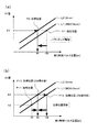
次に、図3を用いて、本実施形態における絞りトラッキングの駆動について説明する。図3(a)は、焦点距離が変化した際に、絞り値を維持するために、絞り開口径を変化させる様子を示す。図3(a)において、横軸は絞り106の絞り制御パルス位置(単位は、ステッピングモータ112の駆動用のステップ数pls)であり、縦軸は絞り値(AV値またはFno)である。
Next, driving of aperture tracking in the present embodiment will be described with reference to FIG. FIG. 3A shows how the aperture diameter is changed in order to maintain the aperture value when the focal length is changed. In FIG. 3A, the horizontal axis is the aperture control pulse position of the aperture 106 (unit is the number of steps for driving the stepping
図3(a)において、ラインL1は焦点距離がWIDE(10mm)の場合の絞り値AVと絞り制御パルス位置の関係を示し、またラインL2は焦点距離が30mmの場合の絞り値AVと絞り制御パルス位置の関係を示し、ラインL1、L2の絞り値と絞り制御パルス位置の関係は、絞り制御データ記憶部123に記憶されている。
In FIG. 3A, the line L1 shows the relationship between the aperture value AV and the aperture control pulse position when the focal length is WIDE (10 mm), and the line L2 is the aperture value AV and aperture control when the focal length is 30 mm. The relationship between the pulse positions is shown, and the relationship between the aperture values of the lines L1 and L2 and the aperture control pulse position is stored in the aperture control
図3(a)において、P1は現在の絞り値を示している(焦点距離がL1(10mm)、絞り値F=8.0、絞り制御パル位置が100pls)。この状態で、ズーム操作を行うことにより、焦点距離がL1(10mm)からL2(30mm)に変化すると、焦点距離の変化に係らず絞り値F=8.0を維持するために、絞り制御パルス位置を変化させればよい。この絞り制御パルス位置を変化させた目標位置P2は、図3(a)から分かるように、焦点距離L2(30mm)において絞り値F=8.0とするために、絞り制御パルス位置は100plsから80plsに変化させればよい。そこで、絞りトラッキング駆動として、目標位置P2として80plsを設定し、100−80=20、すなわち20pls分、絞り用ステッピングモータ112を駆動すれば良いことが分かる。
In FIG. 3A, P1 indicates the current aperture value (focal length is L1 (10 mm), aperture value F = 8.0, aperture control pulse position is 100 pls). When the focal length is changed from L1 (10 mm) to L2 (30 mm) by performing a zoom operation in this state, an aperture control pulse is used to maintain the aperture value F = 8.0 regardless of the change in the focal length. What is necessary is just to change a position. As can be seen from FIG. 3A, the target position P2 obtained by changing the aperture control pulse position is set to an aperture value F = 8.0 at a focal length L2 (30 mm). What is necessary is just to change to 80pls. Therefore, it is understood that as aperture tracking drive, 80 pls is set as the target position P2, and the
この図3(a)における、焦点距離が変化した際に、絞り値を維持するために、絞り制御パルス位置を変化させる処理は、後述する図7のフローチャートのS228およびS229において実行される。 The process of changing the aperture control pulse position in order to maintain the aperture value when the focal length changes in FIG. 3A is executed in S228 and S229 in the flowchart of FIG. 7 described later.
図3(b)は、カメラ本体200から絞り制御指示のコマンドを送信し、このコマンドを処理している際に、ズーム操作がなされた場合、ズーム操作により焦点距離が変化しても絞り値を維持するために、絞り制御パルス位置を変化させる様子を示す。図3(b)においても、図3(a)と同様に、横軸は絞り106の絞り制御パルス位置であり、縦軸は絞り値である。また、ラインL1、L2も同様である。
FIG. 3B shows a case where an aperture control instruction command is transmitted from the
図3(b)において、現在位置はP11にあり(焦点距離L1(10mm)、絞り値F=4.0、絞り制御パルス位置50pls)、カメラ本体200からの絞り制御指示コマンドによって、絞り値F=8.0に駆動するように指示されたとする。このときの目標位置P12は、焦点距離12mm、絞り値F8.0であるから絞り制御パルス位置は100plsである。従って、目標位置P12に到達するために、目標位置として100plsを設定し、100−50=50pls分、絞り用ステッピングモータ112を駆動すればよい。
In FIG. 3B, the current position is at P11 (focal length L1 (10 mm), aperture value F = 4.0, aperture
しかし、現在位置P11から目標位置P12に向けて駆動中に、ズーム操作がなされ、焦点距離がL1(10mm)からL2(30mm)に変化したとすると、指示された絞り値とするためには、目標位置の更新を行い、目標位置P13に変更する。すなわち、目標位置として、80plsを設定して、絞り用ステッピングモータ112を駆動すれば良い。
However, if the zoom operation is performed during driving from the current position P11 to the target position P12 and the focal length is changed from L1 (10 mm) to L2 (30 mm), in order to obtain the indicated aperture value, The target position is updated and changed to the target position P13. In other words, the
この図3(b)における、カメラ本体からの絞り制御指示の実行中に、焦点距離が変化した際に、絞り値を維持するために、絞り制御パルス位置を変化させる処理は、後述する図7のフローチャートのS221〜S227において実行される。 The processing for changing the aperture control pulse position in order to maintain the aperture value when the focal length changes during execution of the aperture control instruction from the camera body in FIG. This is executed in S221 to S227 of the flowchart of FIG.
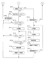
次に、本実施形態に係るカメラ本体200の動作について、図4および図5に示すフローチャートを用いて説明する。このフローは、カメラ本体200内に設けられた本体CPU(不図示)が本体内の記憶部(不図示)に記憶されたプログラムに従って実行する。
Next, the operation of the
カメラ本体200の電源がオンになると、図4および図5に示すフローがスタートする。まず、レンズが装着されているか否かを判定する(S101)。ここでは、カメラ本体200に設けられた装着検知スイッチ等に基づいて、レンズ鏡筒100の装着を判定する。なお、スイッチ以外にも、カメラ本体200内の通信部がレンズ鏡筒100のレンズCPU120と通信可能かによって判定してもよい。
When the power source of the
ステップS101における判定の結果、レンズが装着されていた場合には、次に、レンズ通信を開始する(S102)。ここでは、公知の方法により、通信部を介して、カメラ本体200とレンズ鏡筒100内のレンズCPU120の間で通信を開始する。
If the result of determination in step S101 is that a lens has been attached, lens communication is then started (S102). Here, communication is started between the
次に、スルー画の表示を開始する(S103)。ここでは、カメラ本体200内に設けられた撮像素子からの画像データに基づいて、表示部にスルー画(ライブビュー画像ともいう)の表示を開始する。
Next, display of a through image is started (S103). Here, based on image data from an image sensor provided in the
スルー画の表示を開始すると、次に、レンズが取り外されたか否かを判定する(S104)。ここでは、レンズ装着スイッチの状態等に基づいて、レンズ鏡筒100がカメラ本体200から取り外されたか否かを判定する。この判定の結果、レンズが取り外された場合には、ステップS101に戻る。
Once the live view display is started, it is next determined whether or not the lens is removed (S104). Here, based on the state of the lens mounting switch or the like, it is determined whether or not the
一方、ステップS104における判定の結果、レンズが取り外されていない場合(すなわち、装着されたままの場合)には、次に、電源がオフか否かを判定する(S105)。ここでは、カメラ本体200に設けられた電源スイッチ等の操作部材の操作状態に基づいて判定する。この判定の結果、電源がオフの場合には、終了処理を行い(S106)、このフローを終了する。
On the other hand, if the result of determination in step S104 is that the lens has not been removed (that is, it remains attached), it is next determined whether or not the power is off (S105). Here, the determination is made based on the operation state of an operation member such as a power switch provided in the
一方、ステップS105における判定の結果、電源がオフでない場合(すなわち、電源がオンのままの場合)には、次に、動画モード中か否かを判定する(S107)。例えば、撮影モードダイヤルを動画モードに切り換える等によって、撮影者が動画モードに設定したか否かを判定する。 On the other hand, if the result of determination in step S105 is that the power is not off (ie, the power is still on), it is next determined whether or not it is in the moving image mode (S107). For example, it is determined whether or not the photographer has set the moving image mode by switching the shooting mode dial to the moving image mode.
ステップS107における判定の結果、動画モード中でなければ、次に、絞りプレビューがオンか否かを判定する(S108)。通常、スルー画表示中は、絞り106は開放状態であるが、この状態では実際に絞りこんだ状態での被写界深度を確認することができない。そこで、本実施形態においては、絞りプレビュー釦等、絞りプレビューを操作するための操作部材を設け、この操作部材が操作された場合には、絞り106を手動または自動設定されている絞り値に設定する絞りプレビューを実行する。
If the result of determination in step S107 is not in moving image mode, it is next determined whether or not aperture preview is on (S108). Normally, while the through image is displayed, the
ステップS108における判定の結果、絞りプレビューがオンの場合には、絞り駆動指示を行う(S109)。ここでは、カメラ本体200内の本体CPUは、レンズ鏡筒100内のレンズCPU120に対して、絞り駆動指示のコマンドを出力する。レンズCPU120が、このコマンドを受信すると、ステップS206〜S210(図7参照)において、プレビューを実行する。絞り駆動指示を実行すると、ステップS104に戻る。
If the result of determination in step S108 is that the aperture preview is on, an aperture drive instruction is given (S109). Here, the main body CPU in the camera
ステップS108における判定の結果、絞りプレビューがオンでなかった場合には、次に、1stレリーズがオフか否かを判定する(S110)。撮影者がスルー画を観察しながら、構図をある程度決めると、撮影準備状態として、レリーズ釦の半押しを行う。レリーズ釦の半押し操作に応じて、1stレリーズスイッチがオンとなる。このステップでは、1stレリーズスイッチがオンか否かを判定する。この判定の結果、1stレリーズがオンでない場合、すなわち、レリーズ釦の半押しがなされていない場合には、ステップS104に戻る。 If the result of determination in step S108 is that aperture stop is not on, it is next determined whether or not the first release is off (S110). When the photographer determines the composition to some extent while observing the through image, the release button is pressed halfway as a shooting preparation state. In response to the half-press operation of the release button, the 1st release switch is turned on. In this step, it is determined whether or not the first release switch is on. As a result of the determination, if the first release is not on, that is, if the release button has not been half-pressed, the process returns to step S104.
ステップS110における判定の結果、1stレリーズがオンの場合、すなわち、レリーズ釦の半押しがなされている場合には、AF処理を行う(S111)。ここでは、カメラ本体200内の撮像素子からの画像データに基づくコントラストAF等によって、焦点調節を行う。このとき、カメラ本体200内の本体CPUは、レンズ鏡筒100内のレンズCPU120に対して、フォーカスレンズ群102の駆動のためのコマンドを出力し、焦点調節を行う。
If the result of determination in step S110 is that the first release is on, that is, if the release button is half-pressed, AF processing is performed (S111). Here, focus adjustment is performed by contrast AF or the like based on image data from the image sensor in the
AF処理を行うと、次に、1stレリーズがオフか否かを判定する(S112)。ここでは、ステップS110において撮影者がレリーズ釦を半押しした後、レリーズ釦から指を離したか否かを判定する。この判定の結果1stレリーズがオフであれば、ステップS104に戻る。 Once AF processing has been carried out, it is next determined whether or not the first release is off (S112). Here, it is determined whether or not the photographer has released his / her finger from the release button after half-pressing the release button in step S110. If the result of this determination is that the first release is off, processing returns to step S104.
一方、ステップS112における判定の結果、1stレリーズがオフでなければ、すなわち、レリーズ釦の半押しが継続していれば、次に、2ndレリーズがオンか否かを判定する(S113)。撮影者がスルー画を観察しながら、レリーズ釦の半押しによりピントを合わせ、構図を決定し、撮影を行う場合には、レリーズ釦の全押し(半押しよりもさらに押し込んだ状態)を行う。レリーズ釦の全押し操作に応じて、2ndレリーズスイッチがオンとなる。このステップでは、2ndレリーズスイッチがオンか否かを判定する。この判定の結果、2ndレリーズがオンでない場合、すなわち、レリーズ釦の半押しのままで、全押しされていない場合には、ステップS112に戻る。 On the other hand, if the result of determination in step S112 is that the 1st release is not off, that is, if the release button is half-pressed, it is next determined whether or not the 2nd release is on (S113). When the photographer observes the through image, the release button is pressed halfway to focus, determine the composition, and when shooting, the release button is fully pressed (a state where the release button is pressed further than half-pressed). The 2nd release switch is turned on in response to the full pressing operation of the release button. In this step, it is determined whether or not the 2nd release switch is on. As a result of the determination, if the 2nd release is not on, that is, if the release button is half pressed and not fully pressed, the process returns to step S112.
ステップS113における判定の結果、2ndレリーズがオンとなると、撮影処理を行う(S114)。ここでは、カメラ本体CPUは、絞り106やシャッタを適正露光となるように制御し、撮像素子から静止画の画像データを取得し、これを画像処理する。
If the result of determination in step S113 is that the second release is on, shooting processing is performed (S114). Here, the camera body CPU controls the
撮影処理を行うと、画像データを記憶する(S115)。ここでは、ステップS114における撮影処理において記録用に画像処理された画像データをカメラ本体内の記録媒体に記録する。画像データの記憶を行うと、ステップS104に戻る。 When the photographing process is performed, the image data is stored (S115). Here, the image data subjected to image processing for recording in the photographing processing in step S114 is recorded on a recording medium in the camera body. When the image data is stored, the process returns to step S104.
ステップS107における判定の結果、動画モード中であった場合には、次に、動画録画釦がオンか否かを判定する(S116)。撮影者がスルー画を観察し、動画撮影を開始させるには、動画録画釦を操作するので、このステップでは、動画録画釦の操作状態に基づいて判定する。この判定の結果、動画録画釦が操作されていない場合には、ステップS104に戻る。 If the result of determination in step S107 is that it is in video mode, it is next determined whether or not the video recording button is on (S116). Since the photographer observes the through image and starts moving image shooting, the moving image recording button is operated. In this step, determination is made based on the operation state of the moving image recording button. If the result of this determination is that the movie recording button has not been operated, processing returns to step S104.
一方、ステップS116における判定の結果、動画録画釦がオンの場合には、AF処理を行い(S117)、またAE処理を行う(S118)。AF処理は、カメラ本体200内の撮像素子からの画像データに基づくコントラストAF等によって、焦点調節を行う。このとき、カメラ本体200内の本体CPUは、レンズ鏡筒100内のレンズCPU120に対して、フォーカスレンズ群102の駆動のためのコマンドを出力し、焦点調節を行う。ステップS111におけるAF処理では、いわゆるシングルAF(1回、合焦すると、焦点調節動作を終了する)でもよいが、ステップS117においては、いわゆるコンティニュアスAF(合焦後、ピントがずれると再度自動焦点調節を行い、常に合焦状態を維持するような自動焦点調節)によるAF処理を行う。
On the other hand, if the result of determination in step S116 is that the video recording button is on, AF processing is performed (S117) and AE processing is performed (S118). In the AF process, focus adjustment is performed by contrast AF based on image data from the image sensor in the
また、ステップS118におけるAE処理は、カメラ本体200内の撮像素子からの画像データに基づいて取得した輝度情報に基づいて、適正露光となるように、絞り106、撮像素子の電子シャッタ、ISO感度等を制御する。絞り106の制御にあたって、本体CPUは、レンズCPU120に対して絞り制御用のコマンドを出力する。
Further, the AE process in step S118 is performed such that the
AF処理およびAE処理を行うと、動画録画を行い(S119)、録画データの記憶を行う(S120)。ここでは、撮像素子から動画の画像データを取得し、これを動画記録用に画像処理し、この処理された画像データをカメラ本体内の記録媒体に記録する。 When AF processing and AE processing are performed, moving image recording is performed (S119), and recording data is stored (S120). Here, moving image data is acquired from the image sensor, image processing is performed for moving image recording, and the processed image data is recorded on a recording medium in the camera body.
録画データ記憶を行うと、次に、動画録画釦がオフか否かを判定する(S121)。ここでは、ステップS116においてオンとした動画録画釦をオフとしたか、すなわち、動画録画釦の押し込みを解除したか否かを判定する。なお、本実施形態においては、動画録画釦を押し込んでいる間、動画の録画を行うようにしているが、これに限らず、例えば、動画録画釦を押し込むと動画の録画を開始し、以後、動画録画釦から指を離しても動画の録画を続行し、再度、動画録画釦を押し込むと動画の録画を終了するようにしてもよい。 Once the recording data is stored, it is next determined whether or not the moving image recording button is off (S121). Here, it is determined whether or not the moving image recording button turned on in step S116 is turned off, that is, whether or not the moving image recording button is released. In this embodiment, the video recording is performed while the video recording button is pressed. However, the present invention is not limited to this. For example, when the video recording button is pressed, video recording is started. Recording of the moving image may be continued even if the finger is released from the moving image recording button, and when the moving image recording button is pressed again, the recording of the moving image may be terminated.
ステップS121における判定の結果、動画録画釦がオフでなかった場合、すなわち、動画録画釦が操作されたままであった場合には、ステップS117に戻り、動画の録画を続行する。一方、ステップS121における判定の結果、動画録画釦がオフであった場合、すなわち、動画録画釦の操作が解除された場合には、動画の録画を終了し、ステップS104に戻る。 If the result of determination in step S121 is that the video recording button is not off, that is, if the video recording button has been operated, the flow returns to step S117 to continue video recording. On the other hand, if the result of determination in step S121 is that the video recording button is off, that is, if the operation of the video recording button is canceled, video recording is terminated, and processing returns to step S104.
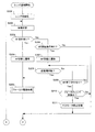
次に、本実施形態に係るレンズ鏡筒100の動作について、図6および図7に示すフローチャートを用いて説明する。このフローは、レンズ鏡筒100内に設けられたレンズCPU120が本体内の記憶部に記憶されたプログラムに従って実行する。
Next, the operation of the
レンズ鏡筒100の電源がオンになると、図6および図7に示すフローがスタートする。まず、レンズの初期化を行う(S201)。ここでは、撮影レンズ101〜105、絞り106等の機械的位置が初期位置となるように機械的初期化を行い、また各種フラグ等、電気的初期化を行う。
When the power of the
レンズ初期化を行うと、次に、待機状態となる(S202)。レンズ鏡筒100は、カメラ本体200からの動作を指示するコマンドを受信しないと、またはズーム環や距離環等のレンズ鏡筒100に設けられた操作部材の操作がないと、動作を開始しない。このステップでは、カメラ本体からのコマンドの受信等を待機し、コマンドを受信または操作部材が操作されると、ステップS203に進む。
Once lens initialization has been performed, a standby state is entered (S202). The
待機状態を脱すると、AF指示があるか否かを判定する(S203)。カメラ本体100において、ステップS111やS117等において、AF処理を行うと、本体側の焦点検出に応じて、レンズCPU120に対して、フォーカスレンズ群102を駆動するためのコマンドを送信する。このステップでは、このAF指示のためのコマンドを受信したかに基づいて判定する。
After leaving the standby state, it is determined whether or not there is an AF instruction (S203). In the camera
ステップS203における判定の結果、AF指示があった場合には、AF状態に遷移し(S204)、フォーカス駆動を実行する(S205)。ここでは、コマンド処理部122がAF状態に遷移し、カメラ本体200からの指示に従ってフォーカス制御部125が目標位置に向け、目標速度でFCS群用ステッピングモータ111の駆動制御を行う。ステップS205におけるフォーカス駆動処理の詳しい動作について、図8を用いて後述する。
If the result of determination in step S203 is that there is an AF instruction, the state transitions to the AF state (S204), and focus drive is executed (S205). Here, the
ステップS203における判定の結果、AF指示がない場合には、次に、MF開始指示が有るか否かを判定する(S206)。レンズ鏡筒100のピント合わせは、AF(自動焦点調節)とMF(手動焦点調節)の2種類があり、カメラ本体200側でAFとMFの設定が可能である、このステップでは、カメラ本体200側でMFモードが設定されたか否かをカメラ本体側からのコマンドに基づいて判定する。
If the result of determination in step S203 is that there is no AF instruction, it is next determined whether or not there is an MF start instruction (S206). There are two types of focusing of the
ステップS206における判定の結果、MF開始時指示が有る場合には、MF状態に遷移し(S207)、距離環が回転されたか否かを判定する(S208)。ここでは、コマンド処理部122がMF状態に遷移し、レンズ鏡筒100の外周に設けられた回転自在の距離環の回転方向と回転量に応じて、MF(手動焦点調節)を実行する。ステップS208における判定の結果、距離環が回転している場合には、ステップS205に進み、検出した回転方向と回転量に応じて手動焦点調節を行う。
If the result of determination in step S206 is that there is an MF start instruction, the state transitions to the MF state (S207), and it is determined whether or not the distance ring has been rotated (S208). Here, the
ステップS208における判定の結果、距離環が回転していない場合には、次に、MF終了指示が有るか否かを判定する(S209)。ここでは、カメラ本体側において、MFモードの設定が解除されたか否かをカメラ本体側からのコマンドに基づいて判定する。この判定の結果、MF終了指示が有る場合には、ステップS208に戻り、MFモードを続行する。 If the result of determination in step S208 is that the distance ring is not rotating, it is next determined whether or not there is an MF end instruction (S209). Here, it is determined on the camera body side based on a command from the camera body side whether or not the setting of the MF mode has been canceled. If the result of this determination is that there is an MF termination instruction, the flow returns to step S208 to continue the MF mode.
ステップS209における判定の結果、MF終了指示が有った場合には、次に、フォーカスレンズ駆動中か否かを判定する(S210)。ステップS208において距離環が操作されると、FCS群用ステッピングモータ111がフォーカスレンズ群102を駆動するが、距離環の動きに対してフォーカスレンズ群102の駆動には遅延がある。このため、MF終了指示が有った場合でもフォーカスレンズ群102の駆動が終了していないことがある。
If the result of determination in step S209 is that there is an MF termination instruction, it is next determined whether or not the focus lens is being driven (S210). When the distance ring is operated in step S208, the FCS
ステップS210における判定の結果、フォーカスレンズが駆動中であった場合には、FCS群用ステッピングモータ111の停止処理を行う(S211)。
If the result of determination in step S210 is that the focus lens is driving, stop processing of the FCS
ステップS205においてフォーカス駆動処理を行うと、またはS206における判定の結果、MF開始指示が無い場合には、またはステップS210における判定の結果、フォーカスレンズが駆動中でない場合、またはステップS211においてFCSモータの停止処理を行うと、次に、絞り制御指示が有るか否かを判定する(S221)。カメラ本体200は、ステップS109の絞りプレビュー時の絞り駆動指示時、ステップS114の撮影処理時、ステップS118の動画録画時のAE処理時等において、絞り制御指示のためのコマンドを、レンズCPU120に対して出力する。このステップS221においては、この絞り制御指示のためのコマンドが送信されてきたか否かを判定する。
When the focus driving process is performed in step S205 or if the result of determination in S206 is that there is no MF start instruction, or if the result of determination in step S210 is that the focus lens is not being driven, or the FCS motor is stopped in step S211 Once processing has been carried out, it is next determined whether or not there is an aperture control instruction (S221). The
ステップS221における判定の結果、絞り制御指示が有る場合には、次に、絞り目標位置を設定し(S222)、絞り目標速度を設定し(S223)し、絞りモータ駆動を開始する(S224)。カメラ本体200は、絞り制御指示のためのコマンドをレンズCPU120に出力する場合には、設定する絞り値を送信してくるので、この絞り値と、現在の焦点距離と、絞り制御データ記憶部123に記憶されているズームレンズ群103の位置と絞り106の開口量との関係を記憶した絞り制御データ記憶部123の記憶値に基づいて、現在の絞り値から受信した絞り値に到達するための駆動ステップ数を演算することにより、絞り目標位置を設定する。そして、この設定された目標位置に向けて駆動する際の絞り目標速度を設定する。絞り目標位置と絞り目標速度を設定すると、絞りモータ(絞り用ステッピングモータ112)によって、絞り106の絞り駆動制御を開始する(図3(b)参照)。
If the result of determination in step S221 is that there is an aperture control instruction, then an aperture target position is set (S222), an aperture target speed is set (S223), and aperture motor drive is started (S224). When the
絞りモータの駆動を開始すると、次に、絞り指示値を記憶する(S225)。ここでは、カメラ本体200から送信されてきた絞り制御指示用のコマンド中にある絞り指示値を絞り制御データ記憶部123に記憶する。これは、絞り制御が終了しないうちに、撮影者がズーム操作を行う場合があり、この場合でも、カメラ本体200から指示された絞り値となるように、絞り106の開口径を制御するためである(ステップS226、S227参照)。
When driving of the aperture motor is started, the aperture instruction value is stored (S225). Here, the aperture instruction value in the aperture control instruction command transmitted from the
絞り指示値を記憶すると、次に、ズーム(ZM)位置変更が発生したか否かを判定する(S226)。ここでは、撮影者がズーム環を回動操作し(またはカメラ本体側のズーム操作部材)、焦点距離が変更したか否かを判定する。焦点距離の変更の発生は、たとえば、ズーム位置検出部114によって検出された焦点距離の時間的変化に基づいて、判定してもよい。
If the aperture instruction value is stored, it is next determined whether or not a zoom (ZM) position change has occurred (S226). Here, the photographer rotates the zoom ring (or the zoom operation member on the camera body side), and determines whether or not the focal length has changed. The occurrence of a change in the focal length may be determined based on, for example, a temporal change in the focal length detected by the zoom
ステップS226における判定の結果、ズーム位置変更が発生した場合には、目標位置の更新を行う(S227)。焦点距離が変わると、カメラ本体200から指示された絞り値とするためには、絞り106の開口径を変えなければならない。このステップでは、カメラ本体200から指示された絞り値となるように、ステップS222において設定された絞り目標位置を変更する(図3(b)参照)。
If the result of determination in step S226 is that the zoom position has changed, the target position is updated (S227). When the focal length changes, in order to obtain the aperture value instructed from the
ステップS221における判定の結果、絞り制御指示がない場合には、次に、ズーム(ZM)位置変更が発生したか否かを判定する(S228)。前述したように、レンズ鏡筒100に設けられたズーム環等を操作すると、光学系の焦点距離が変化する。このステップでは、例えば、ズーム位置検出部114によって検出された焦点距離の時間的変化に基づいて、ズーム位置に変更が生じたか否かを判定する。この判定の結果、ズーム位置の変更が発生していない場合には、ステップS202に戻る。
If the result of determination in step S221 is that there is no aperture control instruction, it is next determined whether or not a zoom (ZM) position change has occurred (S228). As described above, when the zoom ring or the like provided in the
ステップS228における判定の結果、ズーム位置の変更が発生している場合には、次に、絞りトラッキング処理を実行する(S229)。ここでは、ズーム操作により焦点距離が変化しても、カメラ本体200側から指示されている絞り値が維持されるように、絞り106の開口量(開口径)の制御を行う(図3(a)参照)。この絞りトラッキング処理の詳しい動作については、図9を用いて後述する。
If the result of determination in step S228 is that the zoom position has changed, aperture tracking processing is next executed (S229). Here, even if the focal length is changed by the zoom operation, the aperture amount (aperture diameter) of the
ステップS229において絞りトラッキング処理をおこなうと、またはステップS226における判定の結果、ズーム位置変更が発生していない場合、またはステップSステップS227において目標位置更新を行うと、次に、通信終了指示があるか否かを判定する(S230)。カメラ本体200側において、電源がオフする等によって、カメラ本体200とレンズ鏡筒100の間で通信を終了する場合には、レンズ鏡筒100側に電源オフの前に通信終了のコマンドが送信されてくる。そこで、このステップでは、通信終了の指示が有るか否かについて判定する。
If the aperture tracking process is performed in step S229, or if the zoom position change has not occurred as a result of the determination in step S226, or if the target position is updated in step Sstep S227, is there a communication end instruction next? It is determined whether or not (S230). When the communication between the
ステップS230における判定の結果、通信終了の指示がない場合には、ステップS202に戻る。一方、判定の結果、通信終了の指示が有る場合には、通信終了処理を行い(S231)、レンズ通信のフローを終了する。 If the result of determination in step S230 is that there is no communication termination instruction, processing returns to step S202. On the other hand, if there is an instruction to end communication as a result of the determination, communication end processing is performed (S231), and the lens communication flow ends.
このように、レンズ通信のフローにおいては、カメラ本体200から絞り制御のコマンドを受信すると、現在の絞り位置と現在のズーム位置を読み出し、また絞り制御データ記憶部123からズーム位置と絞りの開口量の関係を用いて、現在の絞り値から受信した絞り値に到達するための駆動ステップ数を演算し、絞り用ステッピングモータ112の駆動を行っている(S221〜S224)。このため、ズーム位置に係らず、正確な絞り値に制御することができる。
Thus, in the lens communication flow, when an aperture control command is received from the
また、カメラ本体200から受信した絞り制御のコマンドに基づいて、絞り制御を行っている最中に、ズーム操作がなされた場合には、このズーム操作に基づく焦点距離に変化に応じて、絞りの目標位置を更新している(S226、S227)。このため、カメラ本体200の指示した絞り値に正確に制御することができる。
In addition, when a zoom operation is performed during the aperture control based on the aperture control command received from the
次に、図8を用いて、ステップS205(図6)のフォーカス駆動処理の動作について説明する。フォーカス駆動処理のフローに入ると、まず、目標位置を設定し(S301)、目標速度を設定する(S302)。カメラ本体200側からAF処理のためのコマンドが送信されてくる場合には、目標位置が併せて送られてくる。そこで、レンズCPU120内のフォーカス制御部125は、目標位置に到達するためのFCS群用ステッピングモータ111の駆動パルス数(目標位置)を設定し、また目標位置に到達するまでのパルスレート(目標速度)を設定する。
Next, the focus drive processing operation in step S205 (FIG. 6) will be described with reference to FIG. If the flow of a focus drive process is entered, first, a target position is set (S301), and a target speed is set (S302). When a command for AF processing is transmitted from the
ステップS301およびS302において目標位置と目標速度を設定すると、FCSモータの駆動を開始する(S303)。ここでは、ドライバ113を介してFCS群用ステッピングモータ111を駆動し、フォーカスレンズ群102を目標位置に向けて駆動開始する。
When the target position and target speed are set in steps S301 and S302, driving of the FCS motor is started (S303). Here, the FCS
FCSモータの駆動を開始すると、次に、フォーカスモータ駆動中か否かを判定する(S304)。FCS群用ステッピングモータ111は、ステップS301において設定したステップ数分、駆動を行う。
When driving of the FCS motor is started, it is next determined whether or not the focus motor is being driven (S304). The FCS
ステップS304における判定の結果、フォーカスモータの駆動が終わると、フォーカス制御終了処理を行う(S305)。そして、この終了処理が終わると元のフローに戻る。 If the result of determination in step S304 is that drive of the focus motor has ended, focus control end processing is carried out (S305). Then, when this termination process is completed, the original flow is restored.
次に、図9を用いて、ステップS229(図7)の絞りトラッキング処理の動作について説明する。絞りトラッキング処理のフローに入ると、まず、カメラ本体の最新指示値の読み出しを行う(S401)。カメラ本体200から絞り制御のためのコマンドを受信すると、ステップS225において、絞り指示値を絞り制御データ記憶部123に記憶している。ここでは、絞り制御データ記憶部123に記憶した最新の絞り指示値を読み出す。
Next, the operation of aperture tracking processing in step S229 (FIG. 7) will be described using FIG. When the flow of the aperture tracking process is entered, first, the latest instruction value of the camera body is read (S401). When a command for aperture control is received from the
最新の指示値を読み出すと、次に、現在絞り値(現在の絞り制御パルス位置)plsの読み出しを行う(S402)。本実施形態においては、絞り106の駆動用としてステッピングモータを使用していることから、現在の絞り値は、ステッピングモータの駆動ステップ数のカウント値(絞り制御パルス位置)plsによって求めることができる。
When the latest instruction value is read, the current aperture value (current aperture control pulse position) pls is then read (S402). In this embodiment, since the stepping motor is used for driving the
現在絞り値を読み出すと、次に、現在ズーム(ZM)位置読み出しを行う(S403)。ここでは、ズーム位置検出部114の検出出力に基づいて、現在のズーム位置を読み出す。
Once the current aperture value is read, the current zoom (ZM) position is next read (S403). Here, the current zoom position is read based on the detection output of the zoom
続いて、最新の指示値は現在ズーム(ZM)位置の開放Fno.未満か否かを判定する(S404)。絞り106の開放Fnoは、焦点距離によって変化し、一般に、焦点距離が長くなると、開放Fno.も大きくなる。ステップS401によって読み出したカメラ本体200からの絞り値は、ステップS403において読み出した現在設定されている焦点距離では、設定不可能な場合がある。そこで、このステップでは、カメラ本体200側で設定された絞り値に絞り106が設定可能か否かを判定する。
Subsequently, the latest indicated value is the release Fno. Of the current zoom (ZM) position. It is determined whether it is less than (S404). The open Fno of the
ステップS404における判定の結果、最新の指示値は現在ZM位置の開放Fno.未満の場合には、最新の指示値を現在ZM位置の開放Fno.で丸め込む(S405)。ここでは、カメラ本体200側で設定された絞り値に設定することができないことから、現在設定されている焦点距離における開放Fnoとする。
As a result of the determination in step S404, the latest indicated value is the release Fno. If the value is less than the latest indicated value, the current ZM position release Fno. (S405). Here, since the aperture value set on the
ステップS405における処理を行うと、またはステップS404における判定の結果、最新の指示値は現在ZM位置の開放Fno.未満でなかった場合には、次に、最新の指示値は現在ZM位置の最大Fno.より大きいか否かを判定する(S406)。絞り106は、一番絞り込んだ状態(最大Fno.)よりも更に絞り込むことができず、また、この最大Fno.は、焦点距離によって変化する。そこで、このステップでは、カメラ本体200側で設定された絞り値に絞り106が設定可能か否かを判定する。
When the process in step S405 is performed, or as a result of the determination in step S404, the latest indicated value is the current FNO. If not, it is next determined whether or not the latest indicated value is larger than the maximum Fno. Of the current ZM position (S406). The
ステップS406における判定の結果、最新の指示値は現在ZM位置の最大Fno.より大きい場合には、最新の指示値を現在ZM位置の最大Fno.で丸め込む(S407)。ここでは、カメラ本体200側で設定された絞り値に設定することができないことから、現在設定されている焦点距離における最大Fnoとする。
As a result of the determination in step S406, the latest indicated value is the maximum Fno. If larger, the latest indicated value is set to the maximum Fno. Of the current ZM position. (S407). Here, since the aperture value set on the
ステップS407における処理を行うと、またはステップS406における判定の結果、最新の指示値は現在ZM位置の最大Fno.より大きくなかった場合には、次に、目標絞り位置(絞り制御パルス位置)plsを演算する(S408)。ここでは、ステップS401〜S403において読み出した、カメラ本体から指示された絞り値、現在の絞り値、および現在の焦点距離を用いて、絞り制御データ記憶部123に記憶されているズームレンズ群の位置と絞り制御パルス位置から、目標絞り値に到達するための駆動pls数(ステッピングモータの駆動ステップ数、目標絞り制御パルス位置と現在の絞り制御パルス位置との差)を演算する。
When the processing in step S407 is performed, or as a result of the determination in step S406, the latest instruction value is the maximum Fno. If not, the target aperture position (aperture control pulse position) pls is calculated (S408). Here, the position of the zoom lens group stored in the aperture control
目標絞り位置(絞り制御パルス位置)plsを演算すると、次に絞りモータの駆動を行う(S409)。ここでは、絞り制御部124は、ドライバ113を介して絞り用ステッピングモータ112の駆動制御を行い、絞り106の制御を行う。
Once the target aperture position (aperture control pulse position) pls is calculated, the aperture motor is next driven (S409). Here, the
このように、絞りトラッキング処理においては、ズーム操作により焦点距離が変更されても、この変更前の絞り値が維持されるように、焦点距離の変更に応じて絞り値の開口量(絞り制御パルス位置)を制御している。なお、焦点距離の検出は、図2を用いて説明したように、所定時間間隔で行われており、この時間間隔で絞り106の開口径の制御がなされる。なお、動画録画ボタンが押されて動画録画中である場合には、絞りの開口径の制御は静音動作をする。
As described above, in the aperture tracking process, even if the focal length is changed by a zoom operation, the aperture value (aperture control pulse) of the aperture value is changed according to the change of the focal length so that the aperture value before the change is maintained. Position). The focal length is detected at a predetermined time interval as described with reference to FIG. 2, and the aperture diameter of the
以上説明したように、本発明の一実施形態においては、ズームレンズ群103の位置を検出するズームレンズ位置検出部114と、ズームレンズ群103の位置と絞り106の絞り制御パルス位置との関係を記憶する絞り制御データ記憶部123を有しており、絞り制御データ記憶部123の出力とズームレンズ群103の位置に応じて絞り106の開口量(絞り制御パルス位置)を設定している。このため、ズーム操作による絞り開口の変化や外部からの絞り開口の指示に対応して、高精度な絞り開口量の制御を可能とし、しかも小型化を図っている。
As described above, in one embodiment of the present invention, the zoom lens
また、本発明の一実施形態においては、絞り制御データ記憶部123は、ズームレンズ群103の複数の所定位置に対応する絞り106の複数の開口量に相当する絞り制御パルス位置を記憶し、絞り制御部124は、絞り制御データ記憶部123の出力に基づいて、所定時間間隔でのズームレンズ群103の位置に応じた絞り106の絞り制御パルス位置を演算して絞り106の開口量を制御している(図2、図9参照)。このため、ズーム操作がなされた場合でも、所定時間間隔で絞り106の開口径が制御されるので、一定の絞り値を維持することができ、被写体像の明るさの変動を抑えることができる。
In one embodiment of the present invention, the aperture control
また、本発明の一実施形態においては、外部からの絞り106の開口量に関する指示を入力することが可能であって(例えば、S108の絞りプレビューの指示)、絞り制御データ記憶部123の出力とズームレンズ群103の位置に応じて絞り106の開口量を設定する動作を行っている状態で、外部からの指示が入力された場合に、外部からの指示が入力された時のズームレンズ群103の位置に応じて、絞り制御データ記憶部123の出力に基づき絞り106の開口量を設定し、絞り106の開口量の設定が完了した時のズームレンズ群103の位置に応じて絞り106の開口量を設定し直すようにしている。このため、絞りプレビュー等、外部から絞りの開口量に関する指示を行っても、焦点距離に応じて絞り値に対応する開口量とすることができる。
In one embodiment of the present invention, it is possible to input an instruction regarding the aperture amount of the
なお、本発明の一実施形態の変形例として、絞り制御データ記憶部123は、絞り106の開口量(絞り制御パルス位置)の変化の最小量(最小制御パルス数、たとえば1パルス)に対応してズームレンズ群103の位置を記憶し、絞り制御部124は、絞り制御データ記憶部123の出力に基づいて、最小量に対応するズームレンズ群103の位置に応じて絞り106の開口量を設定するようにしてもよい。このような構成とすることにより、絞り106の開口量の位置を補間演算等によって行うことなく、高精度で制御することができる。
As a modification of the embodiment of the present invention, the aperture control
また、本発明の一実施形態の変形例として、絞り制御部124は、絞り駆動部(絞り用ステッピングモータ112)により絞り106の開口量を変化させる速度を、ズームレンズ群103の移動速度に比例する速度に設定するようにしてもよい。このような構成にすることにより、ズーミングに連動した絞り径の変化とすることができ、ズーム操作によって明るさが変化することを防止することができる。
Further, as a modification of the embodiment of the present invention, the
なお、本発明の一実施形態においては、撮影のための機器として、デジタルカメラを用いて説明したが、カメラとしては、デジタル一眼レフカメラでもコンパクトデジタルカメラでもよく、ビデオカメラ、ムービーカメラのような動画用のカメラでもよく、さらに、携帯電話、スマートフォーンや携帯情報端末(PDA:Personal Digital Assist)、ゲーム機器等に内蔵されるカメラでも構わない。いずれにしても、焦点距離を可変な光学系と、絞りを有する光学機器であれば、本発明を適用することができる。 In the embodiment of the present invention, a digital camera is used as an apparatus for photographing. However, the camera may be a digital single-lens reflex camera or a compact digital camera, such as a video camera or a movie camera. It may be a camera for moving images, or may be a camera built in a mobile phone, a smart phone, a personal digital assistant (PDA), a game machine, or the like. In any case, the present invention can be applied to any optical apparatus having a variable focal length and an optical device having a stop.
また、本明細書において説明した技術のうち、主にフローチャートで説明した制御に関しては、プログラムで設定可能であることが多く、記録媒体や記録部に収められる場合もある。この記録媒体、記録部への記録の仕方は、製品出荷時に記録してもよく、配布された記録媒体を利用してもよく、インターネットを介してダウンロードしたものでもよい。 Of the techniques described in this specification, the control mainly described in the flowchart is often settable by a program and may be stored in a recording medium or a recording unit. The recording method for the recording medium and the recording unit may be recorded at the time of product shipment, may be a distributed recording medium, or may be downloaded via the Internet.
また、特許請求の範囲、明細書、および図面中の動作フローに関して、便宜上「まず」、「次に」等の順番を表現する言葉を用いて説明したとしても、特に説明していない箇所では、この順で実施することが必須であることを意味するものではない。 In addition, regarding the operation flow in the claims, the specification, and the drawings, even if it is described using words expressing the order such as “first”, “next”, etc. It does not mean that it is essential to implement in this order.
本発明は、上記実施形態にそのまま限定されるものではなく、実施段階ではその要旨を逸脱しない範囲で構成要素を変形して具体化できる。また、上記実施形態に開示されている複数の構成要素の適宜な組み合わせにより、種々の発明を形成できる。例えば、実施形態に示される全構成要素の幾つかの構成要素を削除してもよい。さらに、異なる実施形態にわたる構成要素を適宜組み合わせてもよい。 The present invention is not limited to the above-described embodiments as they are, and can be embodied by modifying the constituent elements without departing from the scope of the invention in the implementation stage. In addition, various inventions can be formed by appropriately combining a plurality of components disclosed in the embodiment. For example, you may delete some components of all the components shown by embodiment. Furthermore, constituent elements over different embodiments may be appropriately combined.
100・・・レンズ鏡筒、101・・・撮影レンズ、102・・・フォーカスレンズ群、103・・・ズームレンズ群、104・・・撮影レンズ、105・・・撮影レンズ、106・・・絞り、107・・・鏡枠、111・・・FCS群用ステッピングモータ、112・・・絞り用ステッピングモータ、113・・・ドライバ、114・・・ズーム(ZM)位置検出部、120・・・レンズCPU、121・・・位置検出部、122・・・コマンド処理部、123・・・絞り制御データ記憶部、124・・・絞り制御部、125・・・フォーカス制御部、200・・・カメラ本体
DESCRIPTION OF
Claims (3)
上記光学系を通過する光束を制限する絞り部と、
上記ズームレンズ群の位置を検出するズームレンズ位置検出部と、
上記絞り部の開口量を制御する絞り駆動部と、
上記ズームレンズ位置検出部によって検出された上記ズームレンズ群の位置に応じて、上記絞り駆動部を制御して上記絞り部の開口量を設定する制御部と、
上記ズームレンズ群の位置と上記絞り部の開口量との関係を記憶する記憶部と、
を具備し、
上記制御部は、外部からの上記絞り部の開口量に関する指示を入力することが可能であって、上記外部からの上記絞り部の開口量に関する指示を入力すると、上記指示の開口量を上記記憶部に記憶させるとともに、上記外部から入力された上記絞り部の開口量に関する指示に基づいて上記絞り部の開口量を設定し、
上記指示に基づいて開口量を設定している状態で、上記ズームレンズ群の位置の変化を検出すると、上記ズームレンズ群の位置と上記記憶部に記憶された指示の開口量に応じて上記絞り部の開口量を設定する際の目標位置を更新することを特徴とする光学機器。 An optical system including a zoom lens group;
A diaphragm for limiting the light beam passing through the optical system;
A zoom lens position detector for detecting the position of the zoom lens group;
An aperture drive unit for controlling the aperture of the aperture unit;
A control unit configured to control the diaphragm driving unit to set an aperture amount of the diaphragm unit according to the position of the zoom lens group detected by the zoom lens position detection unit;
A storage unit for storing the relationship between the position of the zoom lens group and the aperture of the diaphragm unit;
Comprising
The control unit can input an instruction regarding the opening amount of the diaphragm unit from the outside. When the instruction regarding the opening amount of the diaphragm unit is input from the outside , the control unit stores the opening amount of the instruction. And setting the aperture amount of the aperture portion based on an instruction regarding the aperture amount of the aperture portion input from the outside,
When a change in the position of the zoom lens group is detected in a state where the opening amount is set based on the instruction, the aperture is set according to the position of the zoom lens group and the opening amount of the instruction stored in the storage unit. An optical apparatus that updates a target position when setting an opening amount of a part .
上記制御部は、上記記憶部の出力に基づいて、所定時間間隔での上記ズームレンズ群の位置に応じた上記絞り部の開口量を演算して上記絞り部の開口量を制御する、
ことを特徴とする請求項1に記載の光学機器。 The storage unit stores a plurality of aperture amounts of the diaphragm unit corresponding to a plurality of predetermined positions of the zoom lens group,
The control unit calculates an aperture amount of the aperture unit according to a position of the zoom lens group at a predetermined time interval based on an output of the storage unit, and controls an aperture amount of the aperture unit;
The optical apparatus according to claim 1.
Priority Applications (1)
| Application Number | Priority Date | Filing Date | Title |
|---|---|---|---|
| JP2013186315A JP6202953B2 (en) | 2013-09-09 | 2013-09-09 | Optical equipment |
Applications Claiming Priority (1)
| Application Number | Priority Date | Filing Date | Title |
|---|---|---|---|
| JP2013186315A JP6202953B2 (en) | 2013-09-09 | 2013-09-09 | Optical equipment |
Publications (3)
| Publication Number | Publication Date |
|---|---|
| JP2015052737A JP2015052737A (en) | 2015-03-19 |
| JP2015052737A5 JP2015052737A5 (en) | 2016-10-20 |
| JP6202953B2 true JP6202953B2 (en) | 2017-09-27 |
Family
ID=52701784
Family Applications (1)
| Application Number | Title | Priority Date | Filing Date |
|---|---|---|---|
| JP2013186315A Active JP6202953B2 (en) | 2013-09-09 | 2013-09-09 | Optical equipment |
Country Status (1)
| Country | Link |
|---|---|
| JP (1) | JP6202953B2 (en) |
Families Citing this family (5)
| Publication number | Priority date | Publication date | Assignee | Title |
|---|---|---|---|---|
| JP6501580B2 (en) * | 2015-03-26 | 2019-04-17 | オリンパス株式会社 | Imaging device, imaging method, and program |
| JP6759549B2 (en) * | 2015-10-19 | 2020-09-23 | 株式会社ニコン | Lens barrel, camera body and program |
| JP6581472B2 (en) * | 2015-11-10 | 2019-09-25 | キヤノン株式会社 | Lens apparatus and imaging apparatus having the same |
| JP6639196B2 (en) * | 2015-11-10 | 2020-02-05 | キヤノン株式会社 | Lens device and imaging device |
| JP2019207334A (en) * | 2018-05-29 | 2019-12-05 | キヤノン株式会社 | Lens device, imaging device, and imaging system |
Family Cites Families (7)
| Publication number | Priority date | Publication date | Assignee | Title |
|---|---|---|---|---|
| JPS5393021A (en) * | 1977-01-25 | 1978-08-15 | Minolta Camera Co Ltd | Aperture control device in variable power lens |
| JPS54147036A (en) * | 1978-05-11 | 1979-11-16 | Fuji Photo Optical Co Ltd | Aperture control unit of zoom lens |
| JPS56135829A (en) * | 1980-03-27 | 1981-10-23 | Fuji Photo Optical Co Ltd | Diaphragm controlling device of zoom lens |
| JPS5850519A (en) * | 1981-09-22 | 1983-03-25 | Canon Inc | Aperture controller |
| JPH0553170A (en) * | 1991-08-29 | 1993-03-05 | Canon Inc | Optical instrument having diaphragm device |
| JP2009157164A (en) * | 2007-12-27 | 2009-07-16 | Konica Minolta Opto Inc | Projection apparatus |
| JP5924927B2 (en) * | 2011-12-22 | 2016-05-25 | キヤノン株式会社 | Imaging device |
-
2013
- 2013-09-09 JP JP2013186315A patent/JP6202953B2/en active Active
Also Published As
| Publication number | Publication date |
|---|---|
| JP2015052737A (en) | 2015-03-19 |
Similar Documents
| Publication | Publication Date | Title |
|---|---|---|
| JP5550304B2 (en) | Imaging device | |
| JP6296698B2 (en) | Camera system and focus adjustment method | |
| JP6560030B2 (en) | Lens unit and aperture control method | |
| JP6749791B2 (en) | Imaging device and automatic focusing method | |
| JP6202953B2 (en) | Optical equipment | |
| JP2007072252A (en) | Lens device, imaging apparatus and imaging system | |
| JP2012252272A (en) | Image pickup apparatus and interchangeable lens | |
| JP6345919B2 (en) | Imaging apparatus and camera system | |
| JP6366295B2 (en) | Optical apparatus and control method | |
| US8488226B2 (en) | Optical apparatus | |
| JP7130412B2 (en) | CONTROL DEVICE, OPTICAL DEVICE, IMAGING DEVICE, AND CONTROL METHOD | |
| JP2011128422A (en) | Imaging apparatus, lens device, and method for detecting focus | |
| JP5465224B2 (en) | Lens apparatus and imaging system | |
| JP6516443B2 (en) | Camera system | |
| JP2017211450A (en) | Imaging apparatus and focus adjustment method | |
| JP2011118021A (en) | Imaging device and method for controlling the same | |
| JP2016109765A (en) | Imaging device and focus adjusting method thereof, and program | |
| JP2006146067A (en) | Camera, lens device and camera system | |
| JP2019004416A (en) | Imaging apparatus, control method for the same, and control program | |
| JP2017223846A (en) | Imaging device and control method of imaging device | |
| JP6257139B2 (en) | Imaging device, lens device, and photographing system | |
| JP6231768B2 (en) | Imaging apparatus and control method thereof | |
| JP6188780B2 (en) | Lens device, control method thereof, and control program | |
| JP6700698B2 (en) | Optical device, display control method, and display control program | |
| JP6429485B2 (en) | Imaging apparatus, communication control method, and imaging system |
Legal Events
| Date | Code | Title | Description |
|---|---|---|---|
| A521 | Request for written amendment filed |
Free format text: JAPANESE INTERMEDIATE CODE: A523 Effective date: 20160901 |
|
| A621 | Written request for application examination |
Free format text: JAPANESE INTERMEDIATE CODE: A621 Effective date: 20160901 |
|
| A977 | Report on retrieval |
Free format text: JAPANESE INTERMEDIATE CODE: A971007 Effective date: 20170419 |
|
| A131 | Notification of reasons for refusal |
Free format text: JAPANESE INTERMEDIATE CODE: A131 Effective date: 20170529 |
|
| A521 | Request for written amendment filed |
Free format text: JAPANESE INTERMEDIATE CODE: A523 Effective date: 20170718 |
|
| TRDD | Decision of grant or rejection written | ||
| A01 | Written decision to grant a patent or to grant a registration (utility model) |
Free format text: JAPANESE INTERMEDIATE CODE: A01 Effective date: 20170802 |
|
| A61 | First payment of annual fees (during grant procedure) |
Free format text: JAPANESE INTERMEDIATE CODE: A61 Effective date: 20170829 |
|
| R151 | Written notification of patent or utility model registration |
Ref document number: 6202953 Country of ref document: JP Free format text: JAPANESE INTERMEDIATE CODE: R151 |
|
| R250 | Receipt of annual fees |
Free format text: JAPANESE INTERMEDIATE CODE: R250 |
|
| S111 | Request for change of ownership or part of ownership |
Free format text: JAPANESE INTERMEDIATE CODE: R313113 |
|
| R350 | Written notification of registration of transfer |
Free format text: JAPANESE INTERMEDIATE CODE: R350 |
|
| R250 | Receipt of annual fees |
Free format text: JAPANESE INTERMEDIATE CODE: R250 |
|
| R250 | Receipt of annual fees |
Free format text: JAPANESE INTERMEDIATE CODE: R250 |
|
| R250 | Receipt of annual fees |
Free format text: JAPANESE INTERMEDIATE CODE: R250 |