JP6201701B2 - Liquid ejection device - Google Patents
Liquid ejection device Download PDFInfo
- Publication number
- JP6201701B2 JP6201701B2 JP2013253224A JP2013253224A JP6201701B2 JP 6201701 B2 JP6201701 B2 JP 6201701B2 JP 2013253224 A JP2013253224 A JP 2013253224A JP 2013253224 A JP2013253224 A JP 2013253224A JP 6201701 B2 JP6201701 B2 JP 6201701B2
- Authority
- JP
- Japan
- Prior art keywords
- ink
- pigment
- white
- unit
- residual vibration
- Prior art date
- Legal status (The legal status is an assumption and is not a legal conclusion. Google has not performed a legal analysis and makes no representation as to the accuracy of the status listed.)
- Active
Links
Images


Classifications
-
- B—PERFORMING OPERATIONS; TRANSPORTING
- B41—PRINTING; LINING MACHINES; TYPEWRITERS; STAMPS
- B41J—TYPEWRITERS; SELECTIVE PRINTING MECHANISMS, i.e. MECHANISMS PRINTING OTHERWISE THAN FROM A FORME; CORRECTION OF TYPOGRAPHICAL ERRORS
- B41J2/00—Typewriters or selective printing mechanisms characterised by the printing or marking process for which they are designed
- B41J2/005—Typewriters or selective printing mechanisms characterised by the printing or marking process for which they are designed characterised by bringing liquid or particles selectively into contact with a printing material
- B41J2/01—Ink jet
- B41J2/015—Ink jet characterised by the jet generation process
- B41J2/04—Ink jet characterised by the jet generation process generating single droplets or particles on demand
- B41J2/045—Ink jet characterised by the jet generation process generating single droplets or particles on demand by pressure, e.g. electromechanical transducers
- B41J2/04501—Control methods or devices therefor, e.g. driver circuits, control circuits
- B41J2/04588—Control methods or devices therefor, e.g. driver circuits, control circuits using a specific waveform
-
- B—PERFORMING OPERATIONS; TRANSPORTING
- B41—PRINTING; LINING MACHINES; TYPEWRITERS; STAMPS
- B41J—TYPEWRITERS; SELECTIVE PRINTING MECHANISMS, i.e. MECHANISMS PRINTING OTHERWISE THAN FROM A FORME; CORRECTION OF TYPOGRAPHICAL ERRORS
- B41J2/00—Typewriters or selective printing mechanisms characterised by the printing or marking process for which they are designed
- B41J2/005—Typewriters or selective printing mechanisms characterised by the printing or marking process for which they are designed characterised by bringing liquid or particles selectively into contact with a printing material
- B41J2/01—Ink jet
- B41J2/015—Ink jet characterised by the jet generation process
- B41J2/04—Ink jet characterised by the jet generation process generating single droplets or particles on demand
- B41J2/045—Ink jet characterised by the jet generation process generating single droplets or particles on demand by pressure, e.g. electromechanical transducers
- B41J2/04501—Control methods or devices therefor, e.g. driver circuits, control circuits
- B41J2/0451—Control methods or devices therefor, e.g. driver circuits, control circuits for detecting failure, e.g. clogging, malfunctioning actuator
-
- B—PERFORMING OPERATIONS; TRANSPORTING
- B41—PRINTING; LINING MACHINES; TYPEWRITERS; STAMPS
- B41J—TYPEWRITERS; SELECTIVE PRINTING MECHANISMS, i.e. MECHANISMS PRINTING OTHERWISE THAN FROM A FORME; CORRECTION OF TYPOGRAPHICAL ERRORS
- B41J2/00—Typewriters or selective printing mechanisms characterised by the printing or marking process for which they are designed
- B41J2/005—Typewriters or selective printing mechanisms characterised by the printing or marking process for which they are designed characterised by bringing liquid or particles selectively into contact with a printing material
- B41J2/01—Ink jet
- B41J2/015—Ink jet characterised by the jet generation process
- B41J2/04—Ink jet characterised by the jet generation process generating single droplets or particles on demand
- B41J2/045—Ink jet characterised by the jet generation process generating single droplets or particles on demand by pressure, e.g. electromechanical transducers
- B41J2/04501—Control methods or devices therefor, e.g. driver circuits, control circuits
- B41J2/04541—Specific driving circuit
-
- B—PERFORMING OPERATIONS; TRANSPORTING
- B41—PRINTING; LINING MACHINES; TYPEWRITERS; STAMPS
- B41J—TYPEWRITERS; SELECTIVE PRINTING MECHANISMS, i.e. MECHANISMS PRINTING OTHERWISE THAN FROM A FORME; CORRECTION OF TYPOGRAPHICAL ERRORS
- B41J2/00—Typewriters or selective printing mechanisms characterised by the printing or marking process for which they are designed
- B41J2/005—Typewriters or selective printing mechanisms characterised by the printing or marking process for which they are designed characterised by bringing liquid or particles selectively into contact with a printing material
- B41J2/01—Ink jet
- B41J2/015—Ink jet characterised by the jet generation process
- B41J2/04—Ink jet characterised by the jet generation process generating single droplets or particles on demand
- B41J2/045—Ink jet characterised by the jet generation process generating single droplets or particles on demand by pressure, e.g. electromechanical transducers
- B41J2/04501—Control methods or devices therefor, e.g. driver circuits, control circuits
- B41J2/04581—Control methods or devices therefor, e.g. driver circuits, control circuits controlling heads based on piezoelectric elements
-
- B—PERFORMING OPERATIONS; TRANSPORTING
- B41—PRINTING; LINING MACHINES; TYPEWRITERS; STAMPS
- B41J—TYPEWRITERS; SELECTIVE PRINTING MECHANISMS, i.e. MECHANISMS PRINTING OTHERWISE THAN FROM A FORME; CORRECTION OF TYPOGRAPHICAL ERRORS
- B41J2/00—Typewriters or selective printing mechanisms characterised by the printing or marking process for which they are designed
- B41J2/005—Typewriters or selective printing mechanisms characterised by the printing or marking process for which they are designed characterised by bringing liquid or particles selectively into contact with a printing material
- B41J2/01—Ink jet
- B41J2/015—Ink jet characterised by the jet generation process
- B41J2/04—Ink jet characterised by the jet generation process generating single droplets or particles on demand
- B41J2/045—Ink jet characterised by the jet generation process generating single droplets or particles on demand by pressure, e.g. electromechanical transducers
- B41J2/04501—Control methods or devices therefor, e.g. driver circuits, control circuits
- B41J2/04593—Dot-size modulation by changing the size of the drop
-
- B—PERFORMING OPERATIONS; TRANSPORTING
- B41—PRINTING; LINING MACHINES; TYPEWRITERS; STAMPS
- B41J—TYPEWRITERS; SELECTIVE PRINTING MECHANISMS, i.e. MECHANISMS PRINTING OTHERWISE THAN FROM A FORME; CORRECTION OF TYPOGRAPHICAL ERRORS
- B41J2/00—Typewriters or selective printing mechanisms characterised by the printing or marking process for which they are designed
- B41J2/005—Typewriters or selective printing mechanisms characterised by the printing or marking process for which they are designed characterised by bringing liquid or particles selectively into contact with a printing material
- B41J2/01—Ink jet
- B41J2/015—Ink jet characterised by the jet generation process
- B41J2/04—Ink jet characterised by the jet generation process generating single droplets or particles on demand
- B41J2/045—Ink jet characterised by the jet generation process generating single droplets or particles on demand by pressure, e.g. electromechanical transducers
- B41J2/04501—Control methods or devices therefor, e.g. driver circuits, control circuits
- B41J2/04596—Non-ejecting pulses
-
- B—PERFORMING OPERATIONS; TRANSPORTING
- B41—PRINTING; LINING MACHINES; TYPEWRITERS; STAMPS
- B41J—TYPEWRITERS; SELECTIVE PRINTING MECHANISMS, i.e. MECHANISMS PRINTING OTHERWISE THAN FROM A FORME; CORRECTION OF TYPOGRAPHICAL ERRORS
- B41J2/00—Typewriters or selective printing mechanisms characterised by the printing or marking process for which they are designed
- B41J2/005—Typewriters or selective printing mechanisms characterised by the printing or marking process for which they are designed characterised by bringing liquid or particles selectively into contact with a printing material
- B41J2/01—Ink jet
- B41J2/135—Nozzles
- B41J2/14—Structure thereof only for on-demand ink jet heads
- B41J2002/14354—Sensor in each pressure chamber
Description
本発明は、液体吐出装置の吐出状態の検査に関する。 The present invention relates to an inspection of a discharge state of a liquid discharge apparatus.
インクジェットタイプのプリンター(以下、インクジェットプリンターという。)は、キャビティ内のインクを吐出することによって印刷を行う。インクは、乾燥すると増粘する。キャビティ内のインクが増粘すると、吐出不良の原因となることがある。また、キャビティ内のインクに気泡が含まれたり、あるいは、紙粉がインクを吐出するノズルに付着すると、吐出不良の原因となることがある。よって、インクの吐出状態を検査することが好ましい。
特許文献1には、圧電素子を用いてキャビティ内のインクに振動を与え、その残留振動に対するインクの挙動を検知することによって、吐出状態を判定する手法が開示されている。
An ink jet type printer (hereinafter referred to as an ink jet printer) performs printing by discharging ink in a cavity. The ink thickens when dried. If the ink in the cavity thickens, it may cause ejection failure. Further, if bubbles in the ink in the cavity or paper dust adheres to the nozzle that ejects ink, it may cause ejection failure. Therefore, it is preferable to inspect the ink ejection state.
Japanese Patent Application Laid-Open No. 2004-228561 discloses a method of determining an ejection state by applying vibration to ink in a cavity using a piezoelectric element and detecting the behavior of the ink with respect to the residual vibration.
ところで、液体吐出装置にて利用されるインクの中には、色材や溶剤などの関係上、当該インクに含まれている顔料成分の沈降速度が速いインクが存在する。本明細書において「沈降」とは、一定期間液体(例えばインク)を放置した場合に、液体に含有されていた成分(例えば顔料成分)が沈殿し、液体に含有されていた成分が液体の下層に積もることをいう。沈降成分としては、例えば白色系インクにあっては、白色系顔料を挙げることができ、これに結合または吸着した成分を含む場合がある。
特に、白色系インクは、その組成の都合上、顔料成分の沈降が起きやすい。このようなインクを吐出する場合、キャビティに充填してから吐出するまでの間に、沈降により成分の不均一が発生し、不安定な画像形成となってしまう場合がある。
しかしながら、従来の技術では、インクの増粘が生じたか否かを判定できても、インクの顔料成分の沈降が生じたか否かを判定することはできなかった。
本発明は、上述した事情に鑑みてなされたものであり、インクの顔料成分の沈降が生じたか否かを判定することを解決課題の一つとする。
By the way, among the inks used in the liquid ejecting apparatus, there are inks in which the sedimentation rate of the pigment component contained in the ink is high due to the color material, the solvent, and the like. In this specification, “sedimentation” means that when a liquid (for example, ink) is left for a certain period of time, a component (for example, a pigment component) contained in the liquid is precipitated, and the component contained in the liquid is a lower layer of the liquid. It means to accumulate. As a sedimentation component, for example, in the case of a white ink, a white pigment can be exemplified, and a component bonded or adsorbed thereto may be included.
In particular, white ink tends to cause precipitation of pigment components due to its composition. When such ink is ejected, there is a case where components are nonuniform due to sedimentation between filling the cavity and ejecting it, resulting in unstable image formation.
However, in the conventional technology, even if it can be determined whether or not the ink has increased in viscosity, it has not been possible to determine whether or not the ink pigment component has settled.
The present invention has been made in view of the above-described circumstances, and an object of the present invention is to determine whether or not sedimentation of the pigment component of the ink has occurred.
以上の課題を解決するために、本発明に係る液体吐出装置の一態様は、顔料を含む液体を吐出するノズルと、前記ノズルに連通する圧力室と、前記圧力室に設けられた圧電素子と、を含む吐出部と、前記圧力室を膨張または収縮させるように前記圧電素子を変位させる駆動信号を生成する駆動信号生成部と、前記駆動信号が前記圧電素子に印加されることにより発生した、前記圧力室内の圧力の変化に応じた値を示す前記圧電素子の残留振動波形の周期を検出する残留振動検出部と、前記残留振動検出部で検出された前記残留振動波形の周期に基づいて前記液体の前記顔料の沈降が生じたことを判定する判定部と、を有することを特徴とする。
この発明によれば、圧力室を膨張または収縮させる圧電素子の残留振動波形の周期に基づく簡易な処理で、当該圧力室内で顔料の沈降が生じているか否かが判定される。これにより、吐出部の正常な吐出機能を回復させるために、真にフラッシング処理(圧力室内の液体(例えばインク)を廃棄する処理)が必要な場合にのみ選択的にフラッシング処理を実行し、圧力室内を撹拌する程度の処理で足りる軽度の沈降等の場合には撹拌処理等で対応することが可能となる。これにより、フラッシング処理の実行回数が必要最小限に抑制されるため、インクの無駄な消費が抑制される。
なお、従来のインクジェットプリンターにおいても、吐出異常が生じた際に回復手段による回復処理が実行されるものが存在する。しかしながら、従来のインクジェットプリンターにおいては、インクの顔料成分の沈降が生じたことを判定することができないため、フラッシング処理が真に必要な場合(例えばインクの増粘や重度の沈降状態が生じた場合)以外の場合であっても、フラッシング処理が実行されてしまうことがある。
In order to solve the above problems, an aspect of the liquid ejection device according to the present invention includes a nozzle that ejects a liquid containing a pigment, a pressure chamber that communicates with the nozzle, and a piezoelectric element that is provided in the pressure chamber. Generated by applying the drive signal to the piezoelectric element, a discharge signal containing the discharge chamber, a drive signal generating part for generating a drive signal for displacing the piezoelectric element so as to expand or contract the pressure chamber, A residual vibration detector that detects a period of the residual vibration waveform of the piezoelectric element showing a value corresponding to a change in pressure in the pressure chamber; and the period of the residual vibration waveform detected by the residual vibration detector And a determination unit that determines that the liquid pigment has settled.
According to this invention, it is determined whether or not the pigment has settled in the pressure chamber by a simple process based on the period of the residual vibration waveform of the piezoelectric element that expands or contracts the pressure chamber. As a result, in order to restore the normal ejection function of the ejection unit, the flushing process is selectively executed only when the flushing process (a process for discarding the liquid (eg, ink) in the pressure chamber) is really necessary. In the case of mild sedimentation or the like that only requires a process of stirring the room, it can be handled by a stirring process or the like. As a result, the number of times the flushing process is executed is suppressed to the minimum necessary, and wasteful consumption of ink is suppressed.
Note that some conventional ink jet printers execute a recovery process by a recovery unit when an ejection abnormality occurs. However, in conventional ink jet printers, it cannot be determined that the pigment component of the ink has settled. Therefore, when the flushing process is really necessary (for example, when the ink is thickened or severely settled) In other cases, the flushing process may be executed.
上述した液体吐出装置の一態様において、前記判定部は、前記残留振動波形の周期が所定範囲内である場合、前記液体の状態が正常であると判定し、前記残留振動波形の周期が前記所定範囲より長い場合、前記液体が増粘していると判定し、前記残留振動波形の周期が前記所定範囲より短い場合、前記顔料の沈降が生じていると判定する、ことが好ましい。
この態様によれば、残留振動波形の周期を所定の閾値と比較するという簡易な処理によって、圧力室内で顔料の沈降や液体の増粘が発生しているか否かを判定することができる。
具体的には、残留振動を想定した単振動の計算モデルを示す回路を考えた場合、残留振動の計算モデルは、音圧p、イナータンスm、コンプライアンスCm及び音響抵抗rで表せる。ここで顔料の沈降が発生すると、当該沈降して凝集・固化した顔料成分の重量だけインク重量が減少するため、インクの流路内におけるインク重量が減少してイナータンスmが低下する。これにより、正常吐出時に比べて周波数が高くなる(周期が短くなる)特徴的な残留振動波形が得られる。つまり、沈降状態発生時の残留振動波形は、正常吐出時のそれに比べて、周期Tが小さい波形となる。一方、インクに増粘が生じた場合、音響抵抗rが増加する。この場合、正常吐出時に比べて周波数が極めて低くなる(周期が長くなる)と共に、残留振動が過減衰となる特徴的な残留振動波形が得られる。従って、残留振動波形の周期に基づいて、圧力室内で顔料の沈降やインクの増粘が発生したことを判定できる。
In one aspect of the liquid ejection apparatus described above, the determination unit determines that the state of the liquid is normal when the period of the residual vibration waveform is within a predetermined range, and the period of the residual vibration waveform is the predetermined period. It is preferable to determine that the liquid is thickened when longer than the range, and to determine that the pigment has settled when the period of the residual vibration waveform is shorter than the predetermined range.
According to this aspect, it is possible to determine whether pigment sedimentation or liquid thickening has occurred in the pressure chamber by a simple process of comparing the period of the residual vibration waveform with a predetermined threshold value.
Specifically, when a circuit showing a calculation model of simple vibration assuming residual vibration is considered, the calculation model of residual vibration can be expressed by sound pressure p, inertance m, compliance Cm, and acoustic resistance r. Here, when the precipitation of the pigment occurs, the ink weight decreases by the weight of the pigment component that has settled and agglomerated and solidified. As a result, a characteristic residual vibration waveform having a higher frequency (shorter period) than that during normal ejection can be obtained. That is, the residual vibration waveform when the sedimentation state occurs is a waveform having a period T smaller than that during normal ejection. On the other hand, when the ink is thickened, the acoustic resistance r increases. In this case, it is possible to obtain a characteristic residual vibration waveform in which the frequency is extremely low (the period is long) and the residual vibration is overdamped as compared with the normal ejection. Therefore, based on the period of the residual vibration waveform, it can be determined that pigment settling or ink thickening has occurred in the pressure chamber.
上述した液体吐出装置の一態様において、前記残留振動検出部は、前記残留振動波形の周期及び振幅を検出し、前記判定部は、前記残留振動波形の周期が前記所定周期より短く、且つ、前記残留振動波形の振幅が所定値よりも大きい場合、前記顔料の沈降の程度は、第1沈降状態であると判定し、前記残留振動波形の周期が前記所定周期より短く、且つ、前記残留振動波形の振幅が所定値以下の場合、前記顔料の沈降の程度は、前記第1沈降状態よりも沈降の程度が進行した第2沈降状態であると判定する、ことが好ましい。
この態様によれば、残留振動波形の振幅と周期とを、それぞれ所定の閾値と比較するという簡易な処理によって、圧力室内で生じた沈降の程度を判定することができる。
具体的には、第2沈降状態発生時には、第1沈降状態発生時と同様にイナータンスmが低下し、正常吐出時に比べて残留振動波形の周波数が高くなる(周期Tが短くなる)ものの、第2沈降状態発生時に特有の現象として、沈降して凝集・固化した顔料成分に起因してノズルの径が小さくなったような状態となり、音響抵抗rが増加する。
この音響抵抗rの低下により、残留振動波形の振幅の減衰率も小さくなり、残留振動は、その振幅をゆっくりと下げることとなる。さらには、沈降して凝集・固化した顔料成分により実質的に圧力室内の容積が減少したような状態となる。これにより、残留振動波形の振幅は小さくなる。つまり、第1沈降状態発生時と、第2沈降状態発生時とでは、残留振動波形の振幅の大きさが異なるため、当該振幅の値に基づいてそれらを識別することができる。
In one aspect of the liquid ejecting apparatus described above, the residual vibration detection unit detects a period and amplitude of the residual vibration waveform, and the determination unit has a period of the residual vibration waveform shorter than the predetermined period, and When the amplitude of the residual vibration waveform is larger than a predetermined value, it is determined that the degree of sedimentation of the pigment is the first sedimentation state, the period of the residual vibration waveform is shorter than the predetermined period, and the residual vibration waveform It is preferable that the degree of sedimentation of the pigment is determined to be the second sedimentation state in which the sedimentation degree has progressed more than the first sedimentation state.
According to this aspect, the degree of sedimentation occurring in the pressure chamber can be determined by a simple process of comparing the amplitude and period of the residual vibration waveform with the predetermined threshold value.
Specifically, when the second settling state occurs, the inertance m decreases as in the case of the first settling state, and the frequency of the residual vibration waveform becomes higher (period T becomes shorter) than during normal discharge. (2) As a phenomenon peculiar to the occurrence of the sedimentation state, the nozzle diameter is reduced due to the pigment component that has settled, aggregated and solidified, and the acoustic resistance r increases.
As the acoustic resistance r decreases, the attenuation rate of the amplitude of the residual vibration waveform also decreases, and the residual vibration slowly reduces the amplitude. Further, the volume of the pressure chamber is substantially reduced by the pigment component that has settled and aggregated and solidified. As a result, the amplitude of the residual vibration waveform is reduced. That is, since the magnitude of the amplitude of the residual vibration waveform is different between when the first settling state occurs and when the second settling state occurs, they can be identified based on the amplitude value.
上述した液体吐出装置の一態様において、前記判定部による判定結果に基づいて、前記駆動信号生成部を制御する制御部を含み、前記制御部は、前記判定部によって前記顔料の沈降の程度が前記第1沈降状態であると判定された場合、前記ノズルから前記液体を吐出させずに前記圧力室の前記液体を撹拌するように前記圧力室を膨張または収縮させる撹拌駆動信号を生成するように、前記駆動信号生成部を制御し、前記判定部によって前記顔料の沈降の程度が前記第2沈降状態であると判定された場合、前記圧力室の内部に充填された前記液体を前記ノズルから全部吐出させるフラッシング駆動信号を生成するように、前記駆動信号生成部を制御する、
ことが好ましい。
この態様によれば、吐出部の正常な吐出機能を回復させるために、真にフラッシング処理が必要な場合にのみ選択的にフラッシング処理を実行し、圧力室内を撹拌する程度の処理で足りる軽度の沈降等の場合には撹拌処理等で対応することが可能となる。これにより、フラッシング処理の実行回数が必要最小限に抑制されるため、インクの無駄な消費が抑制される。
In one aspect of the liquid ejection apparatus described above, the control unit includes a control unit that controls the drive signal generation unit based on a determination result by the determination unit, and the control unit determines the degree of sedimentation of the pigment by the determination unit. So as to generate a stirring drive signal for expanding or contracting the pressure chamber so as to stir the liquid in the pressure chamber without discharging the liquid from the nozzle when it is determined to be in the first sedimentation state; When the drive signal generation unit is controlled and the determination unit determines that the degree of sedimentation of the pigment is the second sedimentation state, the liquid filled in the pressure chamber is completely discharged from the nozzle. Controlling the drive signal generation unit to generate a flushing drive signal
It is preferable.
According to this aspect, in order to restore the normal discharge function of the discharge unit, the flushing process is selectively performed only when the flushing process is really necessary, and a mild process that is sufficient to stir the pressure chamber is sufficient. In the case of sedimentation or the like, it can be handled by a stirring process or the like. As a result, the number of times the flushing process is executed is suppressed to the minimum necessary, and wasteful consumption of ink is suppressed.
上述した液体吐出装置の一態様において、前記顔料を含む液体は、白色顔料と、ウレタン樹脂と、を含有する捺染用白色インクジェットインクあって、前記白色顔料の平均粒径と、前記ウレタン樹脂の平均粒径とが、2≦白色顔料の平均粒径/ウレタン樹脂の平均粒径≦12を満たす、ことが好ましい。
この態様によれば、液体は再分散性が高い白色インクジェットインクであるため、従来のインクを用いた場合では回復処理としてフラッシング処理を実行せざるを得ない程度の沈降が生じた場合であっても、撹拌処理の実行で足りるようになる。つまり、フラッシング処理の実行回数を更に抑制することができるため、インクの無駄な消費を更に抑制することができる。
In one aspect of the liquid ejecting apparatus described above, the liquid containing the pigment is a white inkjet ink for printing containing a white pigment and a urethane resin, the average particle diameter of the white pigment, and the average of the urethane resin The particle size preferably satisfies 2 ≦ average particle size of white pigment / average particle size of urethane resin ≦ 12.
According to this aspect, since the liquid is a white inkjet ink having high redispersibility, when the conventional ink is used, sedimentation to the extent that a flushing process must be performed as a recovery process occurs. However, the execution of the stirring process is sufficient. That is, since the number of executions of the flushing process can be further suppressed, wasteful consumption of ink can be further suppressed.
上述した液体吐出装置の一態様は、前記顔料を含む液体は、インクジェット記録用白色系インクであって、平均粒子径が200nm以上400nm以下であり、金属酸化物からなる白色系顔料を含有し、0.5×A≦V≦1.3×Aを満たし、Aは、インクジェット記録用白色系インクに含まれる前記白色系顔料の含有量(質量%)であり、Vは、インクジェット記録用白色系インク中で前記白色系顔料が完全に沈降したとき、インクジェット記録用白色系インクの全体積に占める前記白色系顔料の体積の割合(%)である、ことが好ましい。
この態様によれば、液体は吐出安定性に優れ、白色度の高い画像を記録できるインクジェット記録用白色系インクであるため、白色系顔料を含む沈降物が生じても、これが硬化したり増粘したりしにくいので、インクジェット記録装置に当該白色系インクを供給した状態で長期間保存しても吐出不良が生じにくい。このため、従来のインクを用いた場合では回復処理としてフラッシング処理を実行せざるを得ない程度の沈降が生じた場合であっても、撹拌振動処理の実行で足りるようになる。つまり、フラッシング処理の実行回数を更に抑制することができるため、インクの無駄な消費を更に抑制することができる。
In one aspect of the liquid ejection apparatus described above, the liquid containing the pigment is a white ink for ink jet recording, has an average particle diameter of 200 nm to 400 nm, and contains a white pigment made of a metal oxide. 0.5 × A ≦ V ≦ 1.3 × A is satisfied, A is the content (% by mass) of the white pigment contained in the white ink for inkjet recording, and V is the white system for inkjet recording. When the white pigment is completely settled in the ink, it is preferably a ratio (%) of the volume of the white pigment to the total volume of the white ink for inkjet recording.
According to this aspect, since the liquid is a white ink for inkjet recording that has excellent ejection stability and can record an image with high whiteness, even if a precipitate containing a white pigment is formed, the liquid is cured or thickened. Therefore, even if the white ink is supplied to the ink jet recording apparatus and stored for a long period of time, ejection failure is unlikely to occur. For this reason, in the case where conventional ink is used, even when sedimentation to the extent that the flushing process must be performed as the recovery process occurs, it is sufficient to perform the stirring vibration process. That is, since the number of executions of the flushing process can be further suppressed, wasteful consumption of ink can be further suppressed.
本発明に係る液体吐出装置の制御方法の一態様は、前記顔料を含む液体は、自己分散型顔料と、4級アミノ酸と、アルカンジオールと、を含有し、前記アルカンジオールは、少なくとも1,6−ヘキサンジオールを含み、前記4級アミノ酸は、前記1,6−ヘキサンジオールよりも多く含有される、インクである、ことが好ましい。
この態様によれば、液体は顔料成分の凝集による沈降を抑制でき、自己分散型顔料の分散安定性に優れるインクであるため、フラッシング処理の実行回数を更に抑制することができ、インクの無駄な消費を更に抑制することができる。
In one aspect of the method for controlling a liquid ejection apparatus according to the present invention, the liquid containing the pigment contains a self-dispersing pigment, a quaternary amino acid, and an alkanediol, and the alkanediol contains at least 1,6. -It is preferable that it is an ink containing hexanediol and containing more quaternary amino acids than the 1,6-hexanediol.
According to this aspect, since the liquid is an ink that can suppress sedimentation due to aggregation of the pigment component and has excellent dispersion stability of the self-dispersing pigment, the number of executions of the flushing process can be further suppressed, and the waste of ink can be reduced. Consumption can be further suppressed.
以下、本発明を実施するための形態について図面を参照して説明する。ただし、各図において、各部の寸法及び縮尺は、実際のものと適宜に異ならせてある。また、以下に述べる実施の形態は、本発明の好適な具体例であるから、技術的に好ましい種々の限定が付されているが、本発明の範囲は、以下の説明において特に本発明を限定する旨の記載がない限り、これらの形態に限られるものではない。 Hereinafter, embodiments for carrying out the present invention will be described with reference to the drawings. However, in each figure, the size and scale of each part are appropriately changed from the actual ones. Further, since the embodiments described below are preferable specific examples of the present invention, various technically preferable limitations are attached thereto. However, the scope of the present invention is particularly limited in the following description. Unless otherwise stated, the present invention is not limited to these forms.
<A.実施形態>
本実施形態では、液体吐出装置として、インク(「液体」の一例)を吐出して被記録媒体(例えば記録用紙)に画像を形成するインクジェットプリンターを例示して説明する。
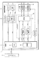
図1は、本実施形態に係るインクジェットプリンター1の構成を示す機能ブロック図である。同図に示すように、インクジェットプリンター1は、内部に充填されたインクを吐出可能な吐出部35をM個(Mは、2以上の自然数)具備するヘッド部30と、ヘッド部30を駆動するヘッドドライバー50と、被記録媒体に対するヘッド部30の相対位置を移動させるための給紙位置移動部4と、吐出部35において「吐出異常を引き起こし得るインクの状態(以下、単に「吐出異常」という。)」が検出された場合に当該吐出部35の吐出機能を正常に回復させるための回復処理を実行する回復手段70と、を備える。
ここで「吐出異常」は、あくまでも吐出部35のキャビティ内部のインクの状態により検出されるものであり、現実に吐出部35による吐出に異常が生じる前の時点であっても検出され得る。
また、インクジェットプリンター1は、パーソナルコンピューターやデジタルカメラ等のホストコンピューター9から供給された画像データImgに基づいて、給紙位置移動部4、ヘッドドライバー50、及び、回復手段70の動作を制御することで、被記録媒体に画像を形成する印刷処理、吐出部35の吐出異常を検出し且つその原因を判定する吐出異常検出処理、及び、吐出異常が検出された際に当該吐出部35の吐出機能を正常に回復させる回復処理等の各種処理の実行を制御する制御部6と、を備える。
<A. Embodiment>
In the present embodiment, an example of an ink jet printer that ejects ink (an example of “liquid”) and forms an image on a recording medium (for example, recording paper) will be described as the liquid ejecting apparatus.
FIG. 1 is a functional block diagram showing the configuration of the
Here, the “ejection abnormality” is only detected based on the state of the ink inside the cavity of the
The
制御部6は、CPU61と、記憶部62とを備える。記憶部62は、ホストコンピューター9から図示省略したインターフェース部を介して供給される画像データImgをデータ格納領域に格納する不揮発性半導体メモリーの一種であるEEPROM(Electrically Erasable Programmable Read-Only Memory)を備える。また、記憶部62は、被記録媒体の形状についての情報等の印刷処理を実行する際に必要なデータと、吐出異常検出処理により得られた結果を表す吐出異常検出結果データとを一時的に格納し、あるいは印刷処理等の各種処理を実行するための制御プログラムを一時的に展開するRAM(Random Access Memory)を備える。また、記憶部62は、インクジェットプリンター1の各部を制御する制御プログラム等を格納する不揮発性半導体メモリーの一種であるPROMを備える。
The
CPU61は、印刷処理、吐出異常検出処理、及び、回復処理等の各種処理の実行を制御する。より具体的には、CPU61は、ホストコンピューター9から供給される画像データImgを、記憶部62に格納する。また、CPU61は、画像データImg等の記憶部62に格納されている各種データ等に基づいて、給紙位置移動部4の駆動を制御するためのドライバー制御信号Ctr1及びCtr2と、ヘッドドライバー50の駆動を制御するための印刷信号SI、切替制御信号Sw、及び、駆動波形信号Com等の各種信号と、回復手段70の駆動を制御するための各種制御信号とを生成し、これらの信号をインクジェットプリンター1の各部に供給する。これにより、CPU61は、給紙位置移動部4、ヘッドドライバー50、及び、回復手段70の動作を制御し、印刷処理、吐出異常検出処理、及び、回復処理等の各種処理の実行を制御する。なお、制御部6の各構成要素は、図示省略したバスを介して電気的に接続されている。
The
ヘッドドライバー50は、駆動信号生成部51、吐出異常検出部52、及び、切替部53を備える。
駆動信号生成部51は、制御部6から供給される印刷信号SI、及び、駆動波形信号Comに基づいて、ヘッド部30が備える吐出部35を駆動するための駆動信号Vinを生成する。なお、詳細は後述するが、本実施形態において駆動波形信号Comは、駆動波形信号Com-A、Com-B、及びCom-Cの3つの信号を含む。
また、印刷信号SI及び駆動波形信号Comを、「印刷制御信号」と総称する。つまり、駆動信号生成部51は、印刷制御信号に基づいて駆動信号Vinを生成する。
吐出異常検出部52は、吐出部35が駆動信号Vinにより駆動された後に生じる、吐出部35の内部のインクの振動等に起因する吐出部35内部の圧力の変化を残留振動信号Voutとして検出するとともに、残留振動信号Voutに基づいて、当該吐出部35に吐出異常があるか否か及び当該吐出部35におけるインクの吐出状態を判定し、判定結果を判定結果信号Rsとして出力する。
切替部53は、制御部6から供給される切替制御信号Swに基づいて、各吐出部35を、駆動信号生成部51または吐出異常検出部52のいずれか一方に接続させる。
The
The drive
The print signal SI and the drive waveform signal Com are collectively referred to as “print control signal”. That is, the drive
The ejection
The switching
給紙位置移動部4は、ヘッド部30を移動させるための(より正確には、ヘッド部30を搭載するキャリッジ32を移動させるための)キャリッジモーター41と、キャリッジモーター41を駆動するためのキャリッジモータードライバー401と、被記録媒体を搬送するための給紙モーター42と、給紙モーター42を駆動するための給紙モータードライバー402と、を備える。なお、キャリッジモータードライバー401及び給紙モータードライバー402を、モータードライバー40と総称することがある。
The paper feed position moving unit 4 includes a
図2は、第1実施形態に係る記録装置としてのインクジェットプリンター1を示す概略斜視図である。図2に示すように、インクジェットプリンター1は、キャリッジ32を備えている。キャリッジ32は、キャリッジモーター41により駆動されるタイミングベルト103を介し、ガイド部材104に案内されてプラテン105の軸方向に往復移動する。被記録媒体(本例では記録用紙)200は、図示しない搬送機構によってキャリッジ32とプラテン105との間に向かって送られる。
FIG. 2 is a schematic perspective view showing the
キャリッジ32の被記録媒体200に対向する位置には、インクジェット式記録ヘッド300が搭載されている。また、インクジェット式記録ヘッド300の上部には、液体としてのインクを当該インクジェット式記録ヘッド300に供給する背景用インク組成物としての白色系インクが収容された白色系インクカートリッジ106及び着色インク組成物としてのカラー及びブラックインクが収容されたカラーおよびブラックインクカートリッジ107が着脱可能に装填されている。被記録媒体200は、印字等領域Pに配置されて、インクジェット式記録ヘッド300によってインクが吐出され、文字、画像等が記録される。文字、画像等が記録された被記録媒体200は、記録物210として排出される。
本明細書において「白色系インク」とは、社会通念上「白色」と呼称される色で印字等するインク(または「インキ」と称されているもの;以下同様)を意味し、微量着色されているものも含む。また、その顔料を含有するインクが「白色インク、ホワイトインク」などといった名称で呼称/販売されるインク(インキ)を含む。
さらに言えば、「白色系インク」は、例えば当該インクが、「エプソン純正写真用紙<光沢>」(セイコーエプソン社製)に100%duty以上又は写真用紙の表面が十分に被覆される量で記録に用いられた場合に、分光測光器Spectrolino(商品名、GretagMacbeth社製)を用いて、測定条件をD50光源、観測視野を2°、濃度をDIN NB、白色基準をAbs、フィルターをNo、測定モードをReflectanceと設定して、当該インクの明度(L*)及び色度(a*、b*)を計測した場合に、70≦L*≦100、−4.5≦a*≦2、−6≦b*≦2.5を満たすインク(インキ)を含む。
なお、本実施形態において白色系インクは、白色とは限らない記録媒体(例えば、プラスチックや金属)に対して画像を記録するために用いられる場合がある。このような場合に、白色系インクは、例えば、記録媒体の色を消したり、カラー画像の透過性を下げたりするために、下地層の形成に用いられる。なお、本実施形態に係る白色系インクは、これに限らず、白色の記録媒体に用いてもよい。
An ink
In the present specification, the term “white ink” means an ink that is printed in a color called “white” for social wisdom (or what is called “ink”; the same applies hereinafter), and is slightly colored. Including those that are. In addition, the ink containing the pigment includes ink (ink) that is named / sold under a name such as “white ink, white ink”.
Furthermore, “white ink” is recorded, for example, in such an amount that the ink is “Epson genuine photographic paper <glossy>” (manufactured by Seiko Epson) with a 100% duty or more or sufficient coverage of the surface of the photographic paper. Spectrophotometer Spectrolino (trade name, manufactured by GretagMacbeth), measurement conditions are D50 light source, observation field is 2 °, density is DIN NB, white reference is Abs, filter is No, measurement When the mode is set to “Reflectance” and the lightness (L *) and chromaticity (a *, b *) of the ink are measured, 70 ≦ L * ≦ 100, −4.5 ≦ a * ≦ 2, − Ink (ink) satisfying 6 ≦ b * ≦ 2.5 is included.
In this embodiment, the white ink may be used to record an image on a recording medium (for example, plastic or metal) that is not necessarily white. In such a case, the white ink is used for forming a base layer, for example, to erase the color of the recording medium or to reduce the transparency of the color image. The white ink according to the present embodiment is not limited to this, and may be used for a white recording medium.
また、図2に示すように、被記録媒体200が配置されない非印字等領域である、例えば、ホームポジションHには、ノズル(後述)の出口を覆うキャッピング手段120、ポンピング処理する(キャビティ(後述)内のインクを吸引して排出する)吸引ポンプ130、及び、ワイピング処理する(ノズルの出口近傍に付着した紙粉などの異物を拭き取る)ワイピング部材140が配置されている。
Further, as shown in FIG. 2, in a non-printing area where the
以下、本実施形態に係るインクジェットプリンター1による、被記録媒体200への記録方法の概略を説明する。インクジェットプリンター1は、図3(a)に示す記録物210aを形成する第1モード、図3(b)に示す記録物210bを形成する第2モード、および図3(c)に示す記録物210cを形成する第3モード、の記録モードを備えている。ここで「記録物」とは、例えば印字等による記録が為された被記録媒体200のことをいう。
Hereinafter, an outline of a recording method on the
図3(a)に示す記録物210aは、被記録媒体200上に白色系画像Pwとカラー画像Pcと、が隣接して形成されている。図3(b)に示す記録物210bは、被記録媒体200上にカラー画像Pcが形成され、カラー画像Pc上に白色系画像Pwが重なって形成されている。図3(c)に示す記録物210cは、被記録媒体200上に白色画像Pwが形成され、白色系画像Pw上にカラー画像Pcが重なって形成されている。
A recorded
インクジェットプリンター1による記録方法は、記録モードを選択する記録モード選択工程と、選択された記録モードに基づく初めに記録画像を形成する第1記録工程と、第1記録工程によって形成された画像を乾燥する乾燥工程と、乾燥工程の後に選択された記録モードに基づく次の記録画像を形成する第2記録工程と、を備えている。
The recording method using the
(記録モード選択工程)記録モード選択工程は、第1モード、第2モードおよび第3モードのいずれかを選択し、インクジェットプリンター1に備える図示しない操作部により記録モードを選択指定する方法、もしくはインクジェットプリンター1に接続された図示しないパーソナルコンピューターによって記録モードを選択指定する方法などによって記録モードを選択指定する。
(Recording Mode Selection Step) The recording mode selection step is a method of selecting any one of the first mode, the second mode, and the third mode, and selecting and specifying the recording mode with an operation unit (not shown) provided in the
(第1記録工程)記録モード選択工程によって選択された記録モードに基づき、所定のインクを被記録媒体200上にインクジェット法で画像が形成、記録される。第1モードまたは第3モードが選択された場合の第1記録工程では、背景用画像の一例として白色系画像Pwが形成される(以下、背景用画像の一例として白色系画像Pwにより説明する)。被記録媒体200は、印刷本紙等の塗工紙、ポリエチレンテレフタレート、ポリエチレン、ポリプロピレン、ポリ塩化ビニル、金属、ガラスから選択される一種であるのが好ましい。これらの被記録媒体200はインク非吸収性または低吸収性であり、ブリストー(Bristow)法において、接触開始から30msecまでの水吸収量が1ml/m2以下のものである。
(First Recording Step) Based on the recording mode selected in the recording mode selection step, an image is formed and recorded on the
背景用インクは、1気圧下相当の沸点が280℃以上のアルキルポリオールを実質的に含有しないことが好ましい。例えば、1気圧下相当の沸点が188℃のプロピレングリコールは含んでもよいが、1気圧下相当の沸点が280℃以上のグリセリン、1気圧下相当の沸点が280℃以上のポリエチレングリコール、1気圧下相当の沸点が280℃以上のポリプロピレングリコール等は含まない。また、背景用インクは、背景用として用いられるインクであれば特に限定されないが、白色系インク又は光輝性インクである事が好ましい。白色系インクに含まれる、白色系顔料としては、例えば、酸化チタン、酸化亜鉛、酸化ジルコニア、中空樹脂粒子の微粒子を含む顔料を用いることができる。ここで、優れた白色度から酸化チタンの微粒子を含むのが好ましい。白色系顔料の平均粒子径は、特に限定されないが100nm以上1μm以下が好ましく、200nm以上400nm以下であるのがさらに好ましく、250nm以上380nm以下であるのが一層好ましく、最も好ましくは260nm以上350nm以下である。なお、これらの微粒子は、酸化珪素、アルミナ等でコーティングされた微粒子であってもよい。 The background ink preferably contains substantially no alkyl polyol having a boiling point corresponding to 1 atm or higher of 280 ° C. or higher. For example, propylene glycol having a boiling point corresponding to 1 atm of 188 ° C. may be included, but glycerin having a boiling point corresponding to 1 atm of 280 ° C. or higher, polyethylene glycol having a boiling point corresponding to 1 atm of 280 ° C. or higher, Polypropylene glycol having a substantial boiling point of 280 ° C. or higher is not included. The background ink is not particularly limited as long as it is an ink used for background, but is preferably white ink or glitter ink. As the white pigment contained in the white ink, for example, a pigment containing fine particles of titanium oxide, zinc oxide, zirconia oxide and hollow resin particles can be used. Here, it is preferable that fine particles of titanium oxide are included because of excellent whiteness. The average particle diameter of the white pigment is not particularly limited, but is preferably 100 nm to 1 μm, more preferably 200 nm to 400 nm, still more preferably 250 nm to 380 nm, and most preferably 260 nm to 350 nm. is there. These fine particles may be fine particles coated with silicon oxide, alumina or the like.
光輝性インクは、光輝性顔料を含有するものである。光輝性顔料としては、媒体に付着されたときに光輝性を呈しうるものであれば特に限定されないが、例えば、アルミニウム、銀、金、白金、ニッケル、クロム、錫、亜鉛、インジウム、チタン、および銅からなる群より選択される1種または2種以上の合金(金属顔料ともいう)や、パール光沢を有するパール顔料を挙げることができる。パール顔料の代表例としては、二酸化チタン被覆雲母、魚鱗箔、酸塩化ビスマス等の真珠光沢や干渉光沢を有する顔料が挙げられる。 The glitter ink contains a glitter pigment. The glitter pigment is not particularly limited as long as it can exhibit glitter when attached to a medium. For example, aluminum, silver, gold, platinum, nickel, chromium, tin, zinc, indium, titanium, and Examples thereof include one or two or more alloys selected from the group consisting of copper (also referred to as metal pigments) and pearl pigments having pearly luster. Representative examples of pearl pigments include pigments having pearly luster and interference gloss such as titanium dioxide-coated mica, fish scale foil, and bismuth oxychloride.
また、背景用顔料としては、下記(式1)に示す「ストークスの式」によって得られる沈降速度vが2.0×10⁻⁶(cm/s)以上であることが好ましい。ストークスの式によって算出される沈降速度が早い背景用顔料は、第2モードの際に、下地の画像との滲みを起こしやすい。しかし、本願の発明によれば、当該不具合を良好に防止出来る。 In addition, as the background pigment, the sedimentation velocity v obtained by the “Stokes' formula” shown in the following (Formula 1) is preferably 2.0 × 10 −6 (cm / s) or more. The background pigment having a high sedimentation velocity calculated by the Stokes equation is liable to blur with the background image in the second mode. However, according to the invention of the present application, the problem can be prevented well.
v={(ρ−ρw)gR2}/(18η) …(式1)
上記(式1)における、vは沈降速度(cm/s)、ρは顔料の密度(g/cm3)、ρwは20℃における溶媒の密度(g/cm3)、gは重力加速度(m/s2)、Rは顔料の動的光散乱法によって算出される体積基準の平均粒子径(cm)、ηは20℃における溶媒の粘度(Pa・s)である。
v = {(ρ−ρ w ) gR 2 } / (18η) (Formula 1)
In the above (Equation 1), v is the sedimentation velocity (cm / s), ρ is the pigment density (g / cm 3 ), ρw is the solvent density (g / cm 3 ) at 20 ° C., and g is the gravitational acceleration (m / S 2 ), R is the volume-based average particle diameter (cm) calculated by the dynamic light scattering method of pigment, and η is the viscosity (Pa · s) of the solvent at 20 ° C.
第1記録工程で記録される白色系画像Pwは、被記録媒体200に形成されるべた画像であってもよいし、カラーおよびブラックインクによって着色画像が形成される位置に合わせて白色系画像Pwを形成してもよい。白色系画像Pwに記録される着色画像の十分な視認性を得るには、白色系インクを用いて形成する白色系画像Pwの白色度は73以上、より好ましくは75以上がよい。ここで、背景用画像(本実施形態においては白色系画像Pw)の記録に使用される白色系顔料量は0.8g/m2以上、より好ましくは1.0g/m2以上であるのが好ましい。
The white image Pw recorded in the first recording step may be a solid image formed on the
また、白色系インクの表面張力は、30mN/m以下であることが好ましく、28mN/m以下であることがより好ましい。さらに、後述する着色インクとの表面張力の差は、背景用インク組成物としての白色系インクの表面張力をS1(mN/m)、着色インク組成物の表面張力をS2(mN/m)とした場合に、 −5<(S1−S2)<4であることが好ましい。 Further, the surface tension of the white ink is preferably 30 mN / m or less, and more preferably 28 mN / m or less. Further, the difference in surface tension from the colored ink described later is that the surface tension of the white ink as the background ink composition is S1 (mN / m), and the surface tension of the colored ink composition is S2 (mN / m). In this case, −5 <(S1-S2) <4 is preferable.
第2モードにおける第1記録工程では、着色インクを用いてインクジェット法によりカラー画像Pcが形成される。着色インクは、色材を含有し、1気圧下相当の沸点が280℃以上のアルキルポリオールを実質的に含有しない。ここで、着色インクの表面張力は、30mN/m以下であるのが好ましく、28mN/m以下であることがより好ましく、一層好ましくは26mN/m以下でり、さらに好ましくは10mN/m以上28mN/m以下であり、最も好ましくは10mN/m以上26mN/m以下である。 In the first recording process in the second mode, a color image Pc is formed by an inkjet method using colored ink. The colored ink contains a color material and does not substantially contain an alkyl polyol having a boiling point of 280 ° C. or higher under 1 atm. Here, the surface tension of the colored ink is preferably 30 mN / m or less, more preferably 28 mN / m or less, still more preferably 26 mN / m or less, and even more preferably 10 mN / m or more and 28 mN / m or less. m or less, and most preferably 10 mN / m or more and 26 mN / m or less.
(乾燥工程)本願発明において、第2記録工程の前には、活性化エネルギー線(例えば、紫外線)照射工程や乾燥工程を設けても良い。乾燥工程を設けた場合に、乾燥工程は、第1記録工程で形成された白色系画像Pwもしくはカラー画像Pcを乾燥させる。乾燥の方法としては、自然乾燥、加熱乾燥を用いることができる。加熱乾燥としては、温風乾燥、熱源による直接接触のヒーター乾燥、活性化エネルギー線(例えば赤外線)による乾燥等が挙げられる。なお、乾燥工程は、第1記録工程と同時に行われても良い。 (Drying step) In the present invention, an activation energy ray (for example, ultraviolet ray) irradiation step and a drying step may be provided before the second recording step. When the drying process is provided, the drying process dries the white image Pw or the color image Pc formed in the first recording process. As a drying method, natural drying or heat drying can be used. Examples of the heat drying include warm air drying, direct contact heater drying with a heat source, drying with activation energy rays (for example, infrared rays), and the like. The drying process may be performed simultaneously with the first recording process.
第1記録工程において白色系画像Pwが形成される、すなわち第1モードおよび第3モードの場合には、白色系画像の乾燥率を40%〜90%(好ましくは55%〜90%)となるように乾燥することが好ましい。また、第1記録工程においてカラー画像Pcが形成される、すなわち第2モードの場合には、カラー画像Pcの乾燥率を40%〜90%(好ましくは55%〜90%)となるように乾燥することが好ましい。なお、乾燥工程で達成する乾燥率は、第2記録工程で吐出される着色インクが第1記録工程によって形成された白色系画像Pwもしくはカラー画像Pcに到達するまでに達成されていればよい。したがって、乾燥工程は、第1記録工程で被記録媒体200に白色系画像Pwもしくはカラー画像Pcが記録されて、第2記録工程で着色インクもしくは白色系インクが白色系画像Pwもしくはカラー画像Pcに到達するまでの工程であり、第1記録工程から第2記録工程までの間の自然乾燥も乾燥工程に含まれる。
In the first recording step, the white image Pw is formed, that is, in the first mode and the third mode, the drying rate of the white image is 40% to 90% (preferably 55% to 90%). It is preferable to dry as described above. In the first recording step, the color image Pc is formed, that is, in the second mode, the color image Pc is dried so that the drying rate is 40% to 90% (preferably 55% to 90%). It is preferable to do. Note that the drying rate achieved in the drying process only needs to be achieved before the colored ink ejected in the second recording process reaches the white image Pw or the color image Pc formed in the first recording process. Therefore, in the drying process, the white image Pw or the color image Pc is recorded on the
乾燥率は以下の方法によって、算出することが可能である。被記録媒体にインクを付与して画像形成したときの被記録媒体の質量が、乾燥率0%に相当する。そして、所定の乾燥条件下で画像を乾燥させ、被記録媒体の質量変化が実質的に止まった時点が、乾燥率100%に相当する。これら2つのデータ及び乾燥時間を変更させて得たデータ(中間乾燥率)から、同一の乾燥条件下において、被記録媒体の質量変化及び乾燥率の変化を表すことができる。このようにして得られた結果、背景色の画像形成から有色(白色を除く。)
の画像形成までの時間、第2記録工程時の被記録媒体の質量などから、乾燥率を算出することができる。なお、乾燥温度が随時変化する場合には、質量を基準に乾燥率を算出するのが好ましい。
The drying rate can be calculated by the following method. The mass of the recording medium when an image is formed by applying ink to the recording medium corresponds to a drying rate of 0%. The time when the image is dried under predetermined drying conditions and the mass change of the recording medium substantially stops corresponds to a drying rate of 100%. From these two data and data obtained by changing the drying time (intermediate drying rate), it is possible to represent changes in the mass of the recording medium and changes in the drying rate under the same drying conditions. As a result obtained in this way, color (excluding white) is obtained from the image formation of the background color.
The drying rate can be calculated from the time until the image formation, the mass of the recording medium in the second recording step, and the like. In addition, when a drying temperature changes at any time, it is preferable to calculate a drying rate on the basis of mass.
第1記録工程において形成された画像の乾燥工程における乾燥時間は、第3モードの第1記録工程によって形成される白色系画像Pwの乾燥時間、第2モードの第1記録工程によって形成されるカラー画像Pcの乾燥時間を長くすることが好ましい。このように乾燥することにより、後述する第2モードの第2記録工程において被記録媒体200上に形成されたカラー画像Pc上に白色系画像Pwを形成する白色系インクをインクジェット法によって重ねた場合に、カラー画像Pcへの白色系画像Pwのブリード、すなわち混色、滲みなどを抑制することができる。背景用顔料は、着色インクに用いられる着色顔料よりも沈降速度が速い傾向にあるため、第2モードにおける滲みは、第3モードにおける滲みよりも大きい傾向にある。よって、第3モードにおける乾燥状態を高める事が好ましいからである。
The drying time in the drying process of the image formed in the first recording process is the drying time of the white image Pw formed in the first recording process in the third mode, and the color formed in the first recording process in the second mode. It is preferable to lengthen the drying time of the image Pc. When the white ink forming the white image Pw is overlaid by the ink jet method on the color image Pc formed on the
(第2記録工程)選択された記録モードに基づき、第1記録工程において形成された白色形画像Pwもしくはカラー画像Pcに対して、カラー画像Pcもしくは白色系画像Pwが形成される。 (Second recording step) Based on the selected recording mode, a color image Pc or a white image Pw is formed with respect to the white image Pw or the color image Pc formed in the first recording step.
第1モードが選択された場合、第2記録工程では図3(a)に示すように白色形画像Pwに隣接するようにカラー画像Pcが形成され、記録物210aを得ることができる。第2モードが選択された場合、第2記録工程では図3(b)に示すようにカラー画像Pc上に白色形画像Pwが重ねて形成され、記録物210bを得ることができる。また、第3モードが選択された場合、第2記録工程では図3(c)に示すように白色形画像Pw上にカラー画像Pcが重ねて形成され、記録物210cを得ることができる。
When the first mode is selected, in the second recording step, a color image Pc is formed so as to be adjacent to the white image Pw as shown in FIG. 3A, and a recorded
次に、図4及び図5を参照して、ヘッド部30、及び、ヘッド部30が備える吐出部35の構成について説明する。
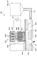
図4は、ヘッド部30が備える各吐出部35の概略的な断面図である。図4に示す吐出部35は、圧電素子500の駆動によりキャビティ445内の液体(本例ではインク)がノズルNから吐出するものである。具体的には、圧電素子500に印加する電圧(駆動信号)を時間的に変化させ、キャビティ445に膨張と収縮とを生じさせることで(キャビティ445の容積を変化させることで)、ノズルNからインクが吐出される。この吐出部35は、ノズルNが形成されたノズルプレート440と、キャビティプレート442と、振動板443と、複数の圧電素子500を積層してなる積層圧電素子501とを備えている。
Next, the configuration of the
FIG. 4 is a schematic cross-sectional view of each
キャビティプレート442は、所定の形状(凹部が形成されるような形状)に成形され、これにより、キャビティ445およびリザーバ446が形成される。キャビティ445とリザーバ446とは、インク供給口447を介して連通している。また、リザーバ446は、インク供給チューブ311を介してインクカートリッジ106,107と連通している。
The
積層圧電素子501の図4中下端は、中間層444を介して振動板443と接合されている。積層圧電素子501には、複数の外部電極448および内部電極449が接合されている。すなわち、積層圧電素子501の外表面には、外部電極448が接合され、積層圧電素子501を構成する各圧電素子500同士の間(または各圧電素子の内部)には、内部電極449が設置されている。この場合、外部電極448と内部電極449の一部が、交互に、圧電素子500の厚さ方向に重なるように配置される。
The lower end in FIG. 4 of the multilayer
そして、外部電極448と内部電極449との間に駆動信号生成部51より駆動電圧波形を印加することにより、積層圧電素子501が図4中の矢印で示すように変形して(図3上下方向に伸縮して)振動し、この振動により振動板443が振動する。この振動板443の振動によりキャビティ445の容積(キャビティ内の圧力)が変化し、キャビティ445内に充填されたインクがノズルNより吐出する。
液体の吐出により、キャビティ445内で減少した液量は、リザーバ446からインクが供給されて補給される。また、リザーバ446へは、インクカートリッジ106,107からインク供給チューブ311を介してインクが供給される。
Then, by applying a drive voltage waveform from the drive
The amount of liquid reduced in the
なお、ノズルプレート440に形成されるノズルN間のピッチは、印刷解像度(dpi:dot per inch)に応じて適宜設定され、その配列パターンの一例としては例えば主走査方向及び副走査方向について互いにずらして配列するパターンを挙げることができる。
Note that the pitch between the nozzles N formed on the
次に、吐出部35の他の例について説明する。図5に示す吐出部35Aは、圧電素子500の駆動により振動板462が振動し、キャビティ458内のインク(液体)がノズルNから吐出するものである。ノズル(孔)Nが形成されたステンレス鋼製のノズルプレート452には、ステンレス鋼製の金属プレート454が接着フィルム455を介して接合されており、さらにその上に同様のステンレス鋼製の金属プレート454が接着フィルム455を介して接合されている。そして、その上には、連通口形成プレート456およびキャビティプレート457が順次接合されている。
Next, another example of the
ノズルプレート452、金属プレート454、接着フィルム455、連通口形成プレート456及びキャビティプレート457は、それぞれ所定の形状(凹部が形成されるような形状)に成形され、これらを重ねることにより、キャビティ458およびリザーバ459が形成される。キャビティ458とリザーバ459とは、インク供給口460を介して連通している。また、リザーバ459は、インク取り入れ口461に連通している。
The
キャビティプレート457の上面開口部には、振動板462が設置され、この振動板462には、下部電極463を介して圧電素子500が接合されている。また、圧電素子500の下部電極463と反対側には、上部電極464が接合されている。駆動信号生成部51は、上部電極464と下部電極463との間に駆動電圧波形を印加(供給)することにより、圧電素子500が振動し、それに接合された振動板462が振動する。この振動板462の振動によりキャビティ458の容積(キャビティ内の圧力)が変化し、キャビティ458内に充填されたインク(液体)がノズルNより液体として吐出する。
A
インクの吐出によりキャビティ458内で減少した液量は、リザーバ459からインクが供給されて補給される。また、リザーバ459へは、インク取り入れ口461からインクが供給される。
The amount of liquid reduced in the
次に、インク滴の吐出について、図6を参照して説明する。駆動信号生成部51から図4(図5についても同様)に示す圧電素子500に駆動電圧が印加されると、電極間にクーロン力が発生し、振動板443(図5においては振動板462;以下同様)は、図6(a)に示す初期状態に対して、図4(図5)中の上方向へ撓み、図6(b)に示すようにキャビティ445(図5においてはキャビティ458;以下同様)の容積が拡大する。この状態において、駆動信号生成部51の制御により、駆動電圧を変化させると、振動板443は、その弾性復元力によって復元し、初期状態における振動板443の位置を越えて下方向に移動し、図6(c)に示すようにキャビティ445の容積が急激に収縮する。このときキャビティ445内に発生する圧縮圧力により、キャビティ445を満たすインク(液状材料)の一部が、このキャビティ445に連通しているノズルNからインク滴として吐出される。
Next, ejection of ink droplets will be described with reference to FIG. When a drive voltage is applied from the
各キャビティ445の振動板443は、この一連のインク吐出動作が終了した後、次のインク吐出動作を開始するまでの間、圧電素子500と一体的に減衰振動をしている。以下、この減衰振動を残留振動とも称する。振動板443及び圧電素子500の残留振動(以下、単に「振動板443」の残留振動という。)は、ノズルNやインク供給口447(図5においてはインク供給口460;以下同様)の形状、あるいはインク粘度等による音響抵抗rと、流路内のインク重量によるイナータンスmと、振動板443のコンプライアンスCmと、によって決定される固有振動周波数を有するものと想定される。
本明細書においてインクの「流路」とは、インクの収容部(例えば白色系インクカートリッジ106)より流出したインクが、ノズルNから吐出されるまでに通る空間のことをいう。例えば、インクジェットプリンター1では、例えば、インク供給チューブ311と、ヘッド部30内のインク流通経路とがインク流路に相当する。
The
In this specification, the “flow path” of ink refers to a space through which ink that has flowed out of the ink container (for example, the white ink cartridge 106) passes through the nozzle N is ejected. For example, in the
上記想定に基づく振動板443の残留振動の計算モデルについて説明する。
図7は、振動板443の残留振動を想定した単振動の計算モデルを示す回路図である。このように、振動板443の残留振動の計算モデルは、音圧pと、上述のイナータンスm、コンプライアンスCm及び音響抵抗rとで表せる。そして、図7の回路に音圧pを与えた時のステップ応答を体積速度uについて計算すると、次式が得られる。
u={p/(ω・m)}e−ωt・sin(ωt) …(式2)
ω={1/(m・Cm)−α2}1/2 …(式3)
α=r/(2m) …(式4)
A calculation model of residual vibration of the
FIG. 7 is a circuit diagram showing a calculation model of simple vibration assuming residual vibration of the
u = {p / (ω · m)} e -ωt · sin (ωt) ... ( Equation 2)
ω = {1 / (m · Cm) −α 2 } 1/2 (Formula 3)
α = r / (2 m) (Formula 4)
この式から得られた計算結果と、別途行ったインク滴の吐出後の振動板443の残留振動の実験における実験結果とを比較する。図8は、振動板443の残留振動の実験値と計算値との関係を示すグラフである。この図8に示すグラフからも分かるように、実験値と計算値の2つの波形は、概ね一致している。
The calculation result obtained from this equation is compared with the experimental result in the residual vibration experiment of the
さて、吐出部35において、前述したような吐出動作を行ったにもかかわらずノズルNからインク滴が正常に吐出されない現象、即ち液体の吐出異常が発生する場合がある。この吐出異常が発生する原因としては、〈原因1〉インクの顔料成分の沈降、〈原因2〉ノズルN近傍でのインクの増粘(乾燥などに起因して粘度が増すこと)、〈原因3〉ノズルNの出口近傍への紙粉付着、等が挙げられる。
In the
この吐出異常が発生すると、その結果としては、典型的にはノズルNから液体が吐出されないこと、即ち液体の不吐出現象が現れ、その場合、被記録媒体200に印刷した画像における画素のドット抜けを生じる。また、吐出異常の場合には、ノズルNから液体が吐出されたとしても、液体の量が過少であったり、その液体の飛行方向(弾道)がずれたりして適正に着弾しないので、やはり画素のドット抜けとなって現れる。このようなことから、以下の説明では、液体の吐出異常のことを単に「ドット抜け」という場合もある。
When this ejection abnormality occurs, typically, as a result, liquid is not ejected from the nozzle N, that is, a liquid non-ejection phenomenon appears. In this case, pixel dots in the image printed on the
以下においては、図8に示す比較結果に基づいて、吐出部35に発生する印刷処理時の吐出異常の原因別に、振動板443の残留振動の計算値と実験値とが概ね一致するように、音響抵抗r及びイナータンスmのうち少なくとも一方の値を調整する。
In the following, based on the comparison result shown in FIG. 8, the calculated value of the residual vibration of the
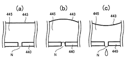
図9(a)(b)は、キャビティ445、リザーバ446、及びインク供給口447内におけるインクの顔料成分の沈降の概念を示す図である。まず、吐出異常の原因の1つである、〈原因1〉キャビティ445内におけるインクの顔料成分の沈降について検討する。
本明細書においては、インクの顔料成分の沈降によって生じる状態を2つの状態に分類する。一の状態(以下、「第1沈降状態」という。)は図9(a)に示す状態であり、主としてノズルNから離隔した部位にインクの顔料成分が沈降(さらには凝集や固化)し、ノズルN近傍にはキャビティ445内の容積が実質的に減少する程度の沈降が生じていない状態である。この状態においては、ノズルN近傍には顔料成分の濃度が薄まったインクが到来する。
他の状態(以下、「第2沈降状態」という。)は図9(b)に示す状態であり、ノズルN近傍においても、当該キャビティ445内の容積が実質的に減少する程度のインクの顔料成分の沈降(さらには凝集や固化)が生じている状態である。
FIGS. 9A and 9B are diagrams illustrating the concept of sedimentation of the pigment component of ink in the
In this specification, the states caused by the sedimentation of the pigment component of the ink are classified into two states. One state (hereinafter, referred to as “first sedimentation state”) is the state shown in FIG. 9A, and the pigment component of the ink settles (and further aggregates and solidifies) mainly at a site separated from the nozzle N. In the vicinity of the nozzle N, there is no settling to the extent that the volume in the
The other state (hereinafter referred to as “second settling state”) is the state shown in FIG. 9B, and the ink pigment is such that the volume in the
図9(a)に示す第1沈降状態においては、凝集・固化した顔料成分の重量だけインク重量が減少するため、結果として流路内のインク重量が減少してイナータンスmが低下するものと考えられる。従って、インクが正常に吐出された図8に示す場合に対してイナータンスmを小さく設定し、第1沈降状態発生時の残留振動の実験値とマッチングすると、正常吐出時に比べて周波数が高くなる(周期Tが短くなる)特徴的な残留振動波形が得られる。つまり、第1沈降状態発生時の残留振動波形は、正常吐出時のそれに比べて、周期Tが小さい波形となる。 In the first sedimentation state shown in FIG. 9A, the ink weight is reduced by the weight of the aggregated and solidified pigment component, and as a result, the ink weight in the flow path is reduced and the inertance m is lowered. It is done. Therefore, when the inertance m is set small with respect to the case shown in FIG. 8 in which the ink is normally ejected and matched with the experimental value of the residual vibration when the first settling state occurs, the frequency becomes higher than that during the normal ejection ( A characteristic residual vibration waveform can be obtained. That is, the residual vibration waveform when the first sedimentation state occurs is a waveform having a period T smaller than that during normal ejection.
図9(b)に示す第2沈降状態においては、第1沈降状態発生時と同様にイナータンスmが低下し、正常吐出時に比べて周波数が高くなる(周期Tが短くなる)。また、第2沈降状態発生時には、ノズルN近傍において凝集・固化した顔料成分に起因して当該ノズルNの径が小さくなったような状態となり、音響抵抗rが増加するものと考えられる。この音響抵抗rの低下により、残留振動波形の振幅の減衰率も小さくなり、残留振動は、その振幅をゆっくりと下げることとなる。
さらには、沈降して凝集・固化した顔料成分がキャビティ445内の流路を狭めるため、実質的にキャビティ445内の容積が減少したような状態となる。このキャビティ445内の容積の減少により、残留振動波形の振幅Aは小さくなるものと考えられる。つまり、第2沈降状態発生時の残留振動波形は、正常吐出時のそれに比べて、周期Tが小さくなり、且つ、振幅Aも小さい波形となる。
In the second settling state shown in FIG. 9B, the inertance m is reduced in the same manner as when the first settling state is generated, and the frequency is increased (the period T is shortened) as compared with the normal discharge. In addition, when the second sedimentation state occurs, it is considered that the diameter of the nozzle N is reduced due to the pigment component aggregated and solidified in the vicinity of the nozzle N, and the acoustic resistance r is increased. As the acoustic resistance r decreases, the attenuation rate of the amplitude of the residual vibration waveform also decreases, and the residual vibration slowly reduces the amplitude.
Furthermore, since the pigment component that has settled and aggregated and solidified narrows the flow path in the
次に、吐出異常のもう1つの原因である、〈原因2〉ノズルN近傍でのインクの増粘について検討する。ノズルN近傍でインクに増粘が生じた場合、キャビティ445内のインクは当該キャビティ445内に閉じこめられた状態となる。具体的には、本例では増粘が生じた状態として、数日間キャッピング手段120を装着させない状態で吐出部35を放置し、ノズルN近傍のインクが乾燥して増粘が生じたことにより、当該インクを吐出することができなくなった状態(ノズルN近傍にインクが固着した状態)を想定している。
このようにノズルN近傍のインクに増粘が生じた場合、音響抵抗rが増加するものと考えられる。インクが正常に吐出された図8の場合に対して、音響抵抗rを大きく設定し、且つ、ノズルN近傍のインクの増粘(乾燥、固着)時の残留振動の実験値とマッチングすることにより、正常吐出時に比べて周波数が極めて低くなると共に、残留振動が過減衰となる特徴的な残留振動波形が得られる。
これは、インク滴を吐出するために振動板443が図4中下方に引き寄せられることによって、キャビティ445内にリザーバ446からインクが流入した後に、振動板443が図4中上方に移動するときに、キャビティ445内のインクの逃げ道がないために、振動板443が急激に振動できなくなるため(過減衰となるため)である。
Next, <cause 2> thickening of ink in the vicinity of the nozzle N, which is another cause of ejection abnormality, will be examined. When the ink is thickened near the nozzle N, the ink in the
Thus, it is considered that the acoustic resistance r increases when the ink near the nozzle N is thickened. In contrast to the case of FIG. 8 in which the ink has been ejected normally, the acoustic resistance r is set to be large and is matched with the experimental value of the residual vibration when the ink near the nozzle N is thickened (drying and fixing). A characteristic residual vibration waveform in which the frequency becomes extremely lower than that during normal ejection and the residual vibration is overdamped is obtained.
This is because when the
次に、吐出異常のさらにもう1つの原因である、〈原因3〉ノズルN出口近傍への紙粉付着について検討する。ノズルNの出口近傍に紙粉が付着した場合、キャビティ445内から紙粉を介してインクが染み出してしまうとともに、ノズルNからインクを吐出することができなくなる。このように、ノズルNの出口近傍に紙粉が付着し、ノズルNからインクが染み出している場合には、振動板443から見てキャビティ445内及び染み出し分のインクが正常時よりも増えることにより、イナータンスmが増加するものと考えられる。また、ノズルNの出口近傍に付着した紙粉の繊維によって音響抵抗rが増大するものと考えられる。
したがって、インクが正常に吐出された図8の場合に対して、イナータンスm、音響抵抗rを共に大きく設定して、ノズルNの出口近傍への紙粉付着時の残留振動の実験値とマッチングすることにより、正常吐出時に比べて周波数が低くなる特徴的な残留振動波形が得られる。ここで、紙粉の付着の場合は、インクの増粘の場合と比較して、残留振動の周波数がより高い(周期Tがより短い)。
Next, the paper powder adhesion near the outlet of the nozzle N, which is still another cause of the ejection abnormality, will be examined. When paper dust adheres to the vicinity of the outlet of the nozzle N, the ink oozes out from the
Therefore, in contrast to the case of FIG. 8 in which the ink has been ejected normally, both the inertance m and the acoustic resistance r are set large to match the experimental value of the residual vibration when paper dust adheres to the vicinity of the nozzle N outlet. Thus, a characteristic residual vibration waveform having a frequency lower than that during normal ejection can be obtained. Here, in the case of adhesion of paper dust, the frequency of residual vibration is higher (period T is shorter) than in the case of thickening ink.
本実施形態に係るインクジェットプリンター1は、各吐出部35におけるノズルNからのインク滴が吐出されたときの振動板443の残留振動の周期Tに基づいて、各吐出部35の吐出異常を検出する。また、その周期Tとその振幅Aとに基づいて、当該吐出異常の原因を特定する。つまり、本実施形態に係るインクジェットプリンター1は、残留振動を解析して吐出異常及びその原因を特定するものである。
The
以下、ヘッドドライバー50(駆動信号生成部51、吐出異常検出部52、及び、切替部53)の構成及び動作について説明する。
Hereinafter, the configuration and operation of the head driver 50 (the drive
図10は、ヘッドドライバー50のうち駆動信号生成部51の構成を示すブロック図である。同図に示すように、駆動信号生成部51は、シフトレジスタSR、ラッチ回路LT、デコーダーDC、並びに、トランスミッションゲートTGa、TGb及びTGcからなる組を、M個の吐出部35に1対1に対応するようにM個有する。以下では、これらM個の組を構成する各要素を、図において上から順番に、1段、2段、…、M段と称することがある。
なお、詳細は後述するが、吐出異常検出部52は、M個の吐出部35に1対1に対応するようにM個の吐出異常検出回路DT(DT[1]、DT[2]、…、DT[M])を具備する。
FIG. 10 is a block diagram illustrating a configuration of the drive
Although details will be described later, the discharge
駆動信号生成部51には、制御部6から、クロック信号CL、印刷信号SI、ラッチ信号LAT、チェンジ信号CH、及び、駆動波形信号Com(Com-A、Com-B、Com-C)が供給される。
ここで、印刷信号SIとは、画像の1ドットを形成するにあたって、各吐出部35(各ノズルN)から吐出させるインク量を規定するデジタルの信号である。より詳細には、本実施形態に係る印刷信号SIは、各吐出部35(各ノズルN)から吐出させるインク量を、上位ビットb1、中位ビットb2および下位ビットb3の3ビットで規定するものであり、制御部6からクロック信号CLに同期して駆動信号生成部51にシリアルで供給される。この印刷信号SIにより、各吐出部35から吐出されるインク量を制御することで、被記録媒体200の各ドットにおいて、非記録、小ドット、中ドットおよび大ドットの4階調を表現することが可能となり、さらに残留振動を発生させてインクの吐出状態を検査するための検査用の駆動信号を生成することが可能となる。
The drive
Here, the print signal SI is a digital signal that defines the amount of ink ejected from each ejection section 35 (each nozzle N) when forming one dot of an image. More specifically, the print signal SI according to the present embodiment defines the amount of ink ejected from each ejection unit 35 (each nozzle N) by three bits, an upper bit b1, a middle bit b2, and a lower bit b3. And is supplied serially from the
シフトレジスタSRのそれぞれは、印刷信号SIを、各吐出部35に対応する3ビット毎に、一旦保持する。詳細には、M個の吐出部35に1対1に対応する、1段、2段、…、M段のM個のシフトレジスタSRが互いに縦続接続されるとともに、印刷信号SIが、クロック信号CLにしたがって順次後段に転送される。そして、M個のシフトレジスタSRの全てに印刷信号SIが転送された時点で、クロック信号CLの供給が停止し、M個のシフトレジスタSRのそれぞれが印刷信号SIのうち自身に対応する3ビット分のデータを保持した状態を維持する。
Each of the shift registers SR temporarily holds the print signal SI for every 3 bits corresponding to each
M個のラッチ回路LTのそれぞれは、ラッチ信号LATが立ち上がるタイミングで、M個のシフトレジスタSRのそれぞれに保持された、各段に対応する3ビット分の印刷信号SIを一斉にラッチする。図15において、SI[1]、SI[2]、…、SI[M]のそれぞれは、1段、2段、…、M段のシフトレジスタSRに対応するラッチ回路LTによってそれぞれラッチされた、3ビット分の印刷信号SIを示している。 Each of the M latch circuits LT simultaneously latches the print signals SI for 3 bits corresponding to the respective stages held in the M shift registers SR at the timing when the latch signal LAT rises. In FIG. 15, SI [1], SI [2],..., SI [M] are respectively latched by the latch circuits LT corresponding to the 1-stage, 2-stage,. A 3-bit print signal SI is shown.
ところで、インクジェットプリンター1が被記録媒体200に画像を形成して印刷を行う期間である印刷動作期間は、複数の単位動作期間Tuからなる。
そして、制御部6は、M個の吐出部35の各々について、単位動作期間Tuを印刷処理又は吐出異常検出処理に割り当てる。制御部6は、3つの態様で吐出部35を制御する。第1の態様は、M個の吐出部35の一部に印刷処理を割り当て、他部に吐出異常検出処理に割り当てる。第2の態様は、M個の吐出部35の全てに印刷処理を割り当てる。第3の態様は、M個の吐出部35の全てに吐出異常検出処理を割り当てる。
各単位動作期間Tuは、制御期間Tc1とこれに後続する制御期間Tc2とからなる。本実施形態では、制御期間Tc1及びTc2は、互いに等しい時間長を有する。
制御部6は、駆動信号生成部51に対して、単位動作期間Tu毎に印刷信号SIを供給し、また、ラッチ回路LTは、単位動作期間Tu毎に印刷信号SI[1]、SI[2]、…、SI[M]をラッチする。
Incidentally, the printing operation period, which is a period during which the
Then, the
Each unit operation period Tu is composed of a control period Tc1 and a control period Tc2 subsequent thereto. In the present embodiment, the control periods Tc1 and Tc2 have the same time length.
The
デコーダーDCは、ラッチ回路LTによってラッチされた3ビット分の印刷信号SIをデコードし、制御期間Tc1及びTc2のそれぞれにおいて、選択信号Sa、Sb及びScを出力する。
図11は、デコーダーDCが行うデコードの内容を示す説明図(テーブル)である。この図に示すように、m段(mは、1≦m≦Mを満たす自然数)に対応する印刷信号SI[m]の示す内容が、例えば(b1、b2、b3)=(1、0、0)である場合、m段のデコーダーDCは、制御期間Tc1において、選択信号SaをハイレベルHに設定するとともに、選択信号Sb及びScをローレベルLに設定し、また、制御期間Tc2において、選択信号Sa及びScをローレベルLに設定するとともに、選択信号SbをハイレベルHに設定する。
また、下位ビットb3が「1」の場合は、上位ビットb1及び中位ビットb2の値に関わらず、m段のデコーダーDCは、制御期間Tc1及びTc2において、選択信号Sa及びSbをローレベルLに設定するとともに、選択信号ScをハイレベルHに設定する。
The decoder DC decodes the 3-bit print signal SI latched by the latch circuit LT, and outputs selection signals Sa, Sb, and Sc in the control periods Tc1 and Tc2, respectively.
FIG. 11 is an explanatory diagram (table) showing the contents of decoding performed by the decoder DC. As shown in this figure, the content indicated by the print signal SI [m] corresponding to m stages (m is a natural number satisfying 1 ≦ m ≦ M) is, for example, (b1, b2, b3) = (1, 0, 0), the m-stage decoder DC sets the selection signal Sa to the high level H and the selection signals Sb and Sc to the low level L in the control period Tc1, and in the control period Tc2, The selection signals Sa and Sc are set to the low level L, and the selection signal Sb is set to the high level H.
When the lower bit b3 is “1”, the m-stage decoder DC outputs the selection signals Sa and Sb to the low level L during the control periods Tc1 and Tc2, regardless of the values of the upper bit b1 and the middle bit b2. And the selection signal Sc is set to the high level H.
説明を図10に戻す。同図に示すように、駆動信号生成部51は、M個の吐出部35に1対1に対応するように、M個のトランスミッションゲートTGa及びTGbの組を備える。
トランスミッションゲートTGaは、選択信号SaがHレベルのときにオンし、Lレベルのときにオフする。トランスミッションゲートTGbは、選択信号SbがHレベルのときにオンし、Lレベルのときにオフする。トランスミッションゲートTGcは、選択信号ScがHレベルのときにオンし、Lレベルのときにオフする。
例えば、m段において、印刷信号SI[m]の示す内容が、(b1、b2、b3)=(1、0、0)である場合には、制御期間Tc1においてトランスミッションゲートTGaがオンするとともにトランスミッションゲートTGb及びTGcがオフし、また、制御期間Tc2においてトランスミッションゲートTGa及びTGcがオフするとともにトランスミッションゲートTGbがオンする。
Returning to FIG. As shown in the figure, the drive
The transmission gate TGa is turned on when the selection signal Sa is at the H level and turned off when the selection signal Sa is at the L level. The transmission gate TGb is turned on when the selection signal Sb is at the H level and turned off when the selection signal Sb is at the L level. The transmission gate TGc is turned on when the selection signal Sc is at the H level and turned off when the selection signal Sc is at the L level.
For example, in the m-th stage, when the content indicated by the print signal SI [m] is (b1, b2, b3) = (1, 0, 0), the transmission gate TGa is turned on and the transmission is performed in the control period Tc1. The gates TGb and TGc are turned off, and the transmission gates TGa and TGc are turned off and the transmission gate TGb is turned on in the control period Tc2.
トランスミッションゲートTGaの一端には駆動波形信号Com-Aが供給され、トランスミッションゲートTGbの一端には駆動波形信号Com-Bが供給され、トランスミッションゲートTGcの一端には駆動波形信号Com-Cが供給される。また、トランスミッションゲートTGa、TGb及びTGcの他端は相互に接続されている。
トランスミッションゲートTGa、TGb及びTGcは排他的にオンとなり、制御期間Tc1及びTc2毎に選択された駆動波形信号Com-A、Com-B、又はCom-Cが、駆動信号Vin[m]として出力され、これが、切替部53を介してm段の吐出部35に供給される。
The drive waveform signal Com-A is supplied to one end of the transmission gate TGa, the drive waveform signal Com-B is supplied to one end of the transmission gate TGb, and the drive waveform signal Com-C is supplied to one end of the transmission gate TGc. The The other ends of the transmission gates TGa, TGb and TGc are connected to each other.
The transmission gates TGa, TGb, and TGc are exclusively turned on, and the drive waveform signal Com-A, Com-B, or Com-C selected for each of the control periods Tc1 and Tc2 is output as the drive signal Vin [m]. This is supplied to the m-
図12は、単位動作期間Tuにおける駆動信号生成部51の動作を説明するためのタイミングチャートである。同図に示すように、単位動作期間Tuは、制御部6が出力するラッチ信号LATにより規定される。また、各単位動作期間Tuは、ラッチ信号LAT及びチェンジ信号CHにより規定される、互いに等しい時間長の制御期間Tc1及びTc2からなる。
FIG. 12 is a timing chart for explaining the operation of the
同図に示されるように、単位動作期間Tuにおいて制御部6から供給される駆動波形信号Com-Aは、単位動作期間Tuのうち制御期間Tc1に配置された単位波形PA1と、制御期間Tc2に配置された単位波形PA2と、を連続させた波形である。単位波形PA1、及び、単位波形PA2の開始及び終了のタイミングにおける電位は、いずれも基準電位Vcである。また、この図に示す通り、単位波形PA1の電位Va11と電位Va12との電位差は、単位波形PA2の電位Va21と電位Va22との電位差よりも大きい。このため、各吐出部35が備える圧電素子500が単位波形PA1により駆動された場合に当該吐出部35が備えるノズルNから吐出されるインクの量は、単位波形PA2により駆動された場合に吐出されるインクの量よりも多い。
As shown in the figure, the drive waveform signal Com-A supplied from the
単位動作期間Tuにおいて制御部6から供給される駆動波形信号Com-Bは、制御期間Tc1に配置された単位波形PB1と、制御期間Tc2に配置された単位波形PB2とを連続させた波形である。単位波形PB1の開始及び終了のタイミングにおける電位は、いずれも基準電位Vcであり、単位波形PB2は制御期間Tc2に亘って基準電位Vcに保たれる。また、単位波形PB1の電位Vb11と基準電位Vcとの電位差は、単位波形PA2の電位Va21と電位Va22との電位差よりも小さい。そして、各吐出部35が備える圧電素子500が単位波形PB1により駆動された場合であっても当該吐出部35が備えるノズルNからはインクは吐出されない。同様に、圧電素子500に単位波形PB2が供給された場合にも、ノズルNからインクが吐出されることはない。
The drive waveform signal Com-B supplied from the
単位動作期間Tuにおいて制御部6から供給される駆動波形信号Com-Cは、制御期間Tc1に配置された単位波形PC1と、制御期間Tc2に配置された単位波形PC2とを連続させた波形である。単位波形PB1の開始及び単位波形PB2の終了のタイミングにおける電位は、いずれも第1電位V1(この例では、基準電位Vc)である。単位波形PB1は、第1電位V1から第2電位V2に遷移し、更に、第2電位V2から第3電位V3に遷移し、第3電位V3に保たれる。また、単位波形PB2は、第3電位V3を保持した後、第3電位V3から第1電位V1に遷移し、第1電位V1に保たれる。駆動波形信号Com-Cはインクの吐出状態を検査する際に選択される。なお、この例の第1電位(基準電位Vc)は、インクの非吐出時において、圧電素子500に保持されるべき電位に設定してある。
The drive waveform signal Com-C supplied from the
上述のとおり、M個のラッチ回路LTは、ラッチ信号LATの立ち上がりのタイミング、すなわち、単位動作期間Tu(TpまたはTt)が開始されるタイミングにおいて、印刷信号SI[1]、SI[2]、…、SI[M]を出力する。
また、m段のデコーダーDCは、上述のとおり、印刷信号SI[m]に応じて、制御期間Tc1及びTc2のそれぞれにおいて、図16に示すテーブルの内容に基づいて選択信号Sa、Sb及びScを出力する。
また、m段のトランスミッションゲートTGa、TGb及びTGcは、上述のとおり、選択信号Sa、Sb及びScに基づいて、駆動波形信号Com-A、Com-B、又はCom-Cのいずれかを選択し、選択した駆動波形信号Comを駆動信号Vin[m]として出力する。
As described above, the M latch circuits LT have the print signals SI [1], SI [2], the timing at which the latch signal LAT rises, that is, the timing at which the unit operation period Tu (Tp or Tt) starts. ..., SI [M] is output.
Further, as described above, the m-stage decoder DC outputs the selection signals Sa, Sb, and Sc based on the contents of the table shown in FIG. 16 in each of the control periods Tc1 and Tc2 in accordance with the print signal SI [m]. Output.
The m-stage transmission gates TGa, TGb, and TGc select one of the drive waveform signals Com-A, Com-B, and Com-C based on the selection signals Sa, Sb, and Sc as described above. The selected drive waveform signal Com is output as the drive signal Vin [m].
図10乃至図12に加え、図13を参照しつつ、単位動作期間Tuにおいて駆動信号生成部51が出力する駆動信号Vinの波形について説明する。
単位動作期間Tuにおいて供給される印刷信号SI[m]の内容が(b1、b2、b3)=(1、1、0)である場合には、制御期間Tc1及び制御期間Tc2において、選択信号Sa、Sb、ScがそれぞれHレベル、Lレベル、Lレベルとなるため、トランスミッションゲートTGaにより駆動波形信号Com-Aが選択され、単位波形PA1及び単位波形PA2が駆動信号Vin[m]として出力される。また、制御期間Tc2において、選択信号Sa、Sb、ScがそれぞれHレベル、Lレベル、Lレベルとなるため、トランスミッションゲートTGaにより駆動波形信号Com-Aが選択され、単位波形PA2が駆動信号Vin[m]として出力される。
この結果、m段の吐出部35は、単位動作期間Tuにおいて、単位波形PA1に基づく中程度の量のインクの吐出、及び、単位波形PA2に基づく小程度の量のインクの吐出がなされ、これら2度にわたり吐出されたインクが被記録媒体200上で合体するため、記録用紙P上には、大ドットが形成される。
The waveform of the drive signal Vin output from the drive
When the content of the print signal SI [m] supplied in the unit operation period Tu is (b1, b2, b3) = (1, 1, 0), the selection signal Sa is used in the control period Tc1 and the control period Tc2. , Sb, and Sc are at the H level, L level, and L level, respectively, the drive waveform signal Com-A is selected by the transmission gate TGa, and the unit waveform PA1 and the unit waveform PA2 are output as the drive signal Vin [m]. . In the control period Tc2, the selection signals Sa, Sb, and Sc are at the H level, L level, and L level, respectively, so that the drive waveform signal Com-A is selected by the transmission gate TGa, and the unit waveform PA2 is the drive signal Vin [ m].
As a result, the m-
単位動作期間Tuにおいて供給される印刷信号SI[m]の内容が(b1、b2、b3)=(1、0、0)である場合には、制御期間Tc1において、選択信号Sa、Sb、ScがそれぞれHレベル、Lレベル、Lレベルとなるため、トランスミッションゲートTGaにより駆動波形信号Com-Aが選択され、単位波形PA1が駆動信号Vin[m]として出力される。また、制御期間Tc2において、選択信号Sa、Sb、ScがそれぞれLレベル、Hレベル、Lレベルとなるため、トランスミッションゲートTGbにより駆動波形信号Com-Bが選択され、単位波形PB2が駆動信号Vin[m]として出力される。
この結果、m段の吐出部35は、単位動作期間Tuにおいて、単位波形PA1に基づく中程度の量のインクの吐出がなされ、記録用紙P上には、中ドットが形成される。
When the content of the print signal SI [m] supplied in the unit operation period Tu is (b1, b2, b3) = (1, 0, 0), the selection signals Sa, Sb, Sc in the control period Tc1. Are respectively at the H level, the L level, and the L level, the drive waveform signal Com-A is selected by the transmission gate TGa, and the unit waveform PA1 is output as the drive signal Vin [m]. In the control period Tc2, the selection signals Sa, Sb, and Sc are at the L level, the H level, and the L level, respectively, so that the drive waveform signal Com-B is selected by the transmission gate TGb, and the unit waveform PB2 m].
As a result, the m-
単位動作期間Tuにおいて供給される印刷信号SI[m]の内容が(b1、b2、b3)=(0、1、0)である場合には、制御期間Tc1において、選択信号Sa、Sb、ScがそれぞれLレベル、Hレベル、Lレベルとなるため、トランスミッションゲートTGbにより駆動波形信号Com-Bが選択され、単位波形PB1が駆動信号Vin[m]として出力される。また、制御期間Tc2において、選択信号Sa、SbがそれぞれHレベル、Lレベル、Lレベルとなるため、トランスミッションゲートTGaにより駆動波形信号Com-Aが選択され、単位波形PA2が駆動信号Vin[m]として出力される。
この結果、m段の吐出部35は、単位動作期間Tuにおいて、単位波形PA2に基づく小程度の量のインクの吐出がなされ、記録用紙P上には、小ドットが形成される。
When the content of the print signal SI [m] supplied in the unit operation period Tu is (b1, b2, b3) = (0, 1, 0), the selection signals Sa, Sb, Sc in the control period Tc1. Are respectively at L level, H level, and L level, the drive waveform signal Com-B is selected by the transmission gate TGb, and the unit waveform PB1 is output as the drive signal Vin [m]. In the control period Tc2, the selection signals Sa and Sb become H level, L level, and L level, respectively, so that the drive waveform signal Com-A is selected by the transmission gate TGa, and the unit waveform PA2 is the drive signal Vin [m]. Is output as
As a result, the m-
単位動作期間Tuにおいて供給される印刷信号SI[m]の内容が(b1、b2、b3)=(0、0、0)である場合には、制御期間Tc1及びTc2において、選択信号Sa、Sb、ScがそれぞれLレベル、Hレベル、Lレベルとなるため、トランスミッションゲートTGbにより駆動波形信号Com-Bが選択され、単位波形PB1及びPB2が駆動信号Vin[m]として出力される。
この結果、m段の吐出部35からは、単位動作期間Tuにおいて、インクの吐出がなされず、記録用紙P上には、ドットが形成されない(非記録となる)。
When the content of the print signal SI [m] supplied in the unit operation period Tu is (b1, b2, b3) = (0, 0, 0), the selection signals Sa and Sb are supplied in the control periods Tc1 and Tc2. , Sc become L level, H level, and L level, respectively, so that the drive waveform signal Com-B is selected by the transmission gate TGb, and the unit waveforms PB1 and PB2 are output as the drive signal Vin [m].
As a result, no ink is ejected from the m-
単位動作期間Tuにおいて供給される印刷信号SI[m]の内容が(b1、b2、b3)=(1or0、1or0、1)である場合には、制御期間Tc1及びTc2において、選択信号Sa、Sb、ScがそれぞれLレベル、Lレベル、Hレベルとなるため、トランスミッションゲートTGcにより駆動波形信号Com-Cが選択され、単位波形PC1及びPC2が駆動信号Vin[m]として出力される。
この結果、m段の吐出部35からは、単位動作期間Tuにおいて、インクの吐出がなされず、インクの吐出状態の検査が行われる。
When the content of the print signal SI [m] supplied in the unit operation period Tu is (b1, b2, b3) = (1or0, 1or0, 1), the selection signals Sa and Sb are used in the control periods Tc1 and Tc2. , Sc become L level, L level, and H level, respectively, the drive waveform signal Com-C is selected by the transmission gate TGc, and the unit waveforms PC1 and PC2 are output as the drive signal Vin [m].
As a result, the m-
図14に、検査用の駆動信号Vin[m]の波形を示す。同図に示すように駆動信号Vin[m]は、時刻t1sから時刻t1eまでの第1期間T1中に第1電位V1となり、時刻t2sから時刻t2eまでの第2期間T2中に第2電位V2となり、時刻t3sから時刻t3eまでの第3期間T3中に第3電位V3となる。また、駆動信号Vin[m]は、第1電位V1から第2電位V2(t1e〜t2s)に遷移し、第2電位V2から第3電位V3に遷移する(t2e〜t3s)に遷移する。 FIG. 14 shows the waveform of the drive signal Vin [m] for inspection. As shown in the figure, the drive signal Vin [m] becomes the first potential V1 during the first period T1 from the time t1s to the time t1e, and the second potential V2 during the second period T2 from the time t2s to the time t2e. And becomes the third potential V3 during the third period T3 from time t3s to time t3e. The drive signal Vin [m] transits from the first potential V1 to the second potential V2 (t1e to t2s) and transits from the second potential V2 to the third potential V3 (t2e to t3s).
この例では、第1電位V1から第2電位V2まで遷移させる時刻t1eから時刻t2sにおいて圧電素子500にチャージされた電荷が放電される。この結果、圧電素子500はメニスカスをキャビティ445の内部に引き込むように加振される。この後、第2期間T2では、第2電位V2を保持し、時刻t2eから時刻t3sにおいて、第2電位V2から第3電位V3に遷移させる。時刻t2eから時刻t3sまでの期間では、圧電素子500に電荷がチャージされる。この結果、圧電素子500はメニスカスをキャビティ445の外部に押し出す方向に変位する。但し、インクがノズルNから吐出しないように第3電位V3が設定されている。仮に、第2電位V2から第1電位V1に遷移させると、圧電素子500の変位が短時間で元の状態に戻り、インクが吐出してしまう。
In this example, the electric charge charged in the
そこで、本実施形態では、第3電位V3が、第1電位V1と第2電位V3との間の電位となるように設定している。即ち、この例では、メニスカスをなるべくキャビティ445の内部に引き込んだ状態から、インクが吐出しないようにメニスカスを戻すことによって、キャビティ445の内部に大きな圧力変化を発生させる。これによって、残留振動を大きな振幅で取り出すことが可能となる。
Therefore, in the present embodiment, the third potential V3 is set to be a potential between the first potential V1 and the second potential V3. That is, in this example, a large pressure change is generated in the
また、本実施形態においては、第1期間T1の終了時刻t1eから第2期間T2の終了時刻t2eまでの時間をTxaとし、キャビティ445の固有振動周期をTcとしたとき、以下のように時間Txaを定めることが好ましい。
キャビティ445内のインクは圧電素子500が撓むことによって加振される。このとき、キャビティ445内の圧力は固有振動周期Tcに同期して増加減少する。一方、第2期間T2の終了時刻t2eは、圧電素子500の変位の方向を変化させるタイミングである。大きな残留振動を得るためには、キャビティ445内の圧力の変化に同期して、圧電素子500の変位の方向を変化させることが好ましい。
In the present embodiment, when the time from the end time t1e of the first period T1 to the end time t2e of the second period T2 is Txa and the natural vibration period of the
The ink in the
本実施形態に係るインクジェットプリンター1は、検査用の駆動信号Vinにより吐出部35を駆動して、その結果生じる当該吐出部35のキャビティ445内部の圧力変化に基づく圧電素子500の起電力の変化を残留振動信号Voutとして検出する。そして、残留振動信号Voutに基づいて当該吐出部35に吐出異常があるか否かについての判定を実行する吐出異常検出処理を実行する。
The
図15は、ヘッドドライバー50のうち切替部53の構成、並びに、切替部53と吐出異常検出部52、ヘッド部30、及び、駆動信号生成部51との電気的な接続関係を示すブロック図である。
同図に示すように、切替部53は、M個の吐出部35に1対1に対応する1段〜M段のM個の切替回路U(U[1]、U[2]、…、U[M])を備える。m段の切替回路U[m]は、m段の吐出部35を、駆動信号Vin[m]が供給される配線、又は吐出異常検出部52が備える吐出異常検出回路DTのいずれか一方に、電気的に接続する。
以下では、各切替回路Uにおいて、吐出部35と駆動信号生成部51とが電気的に接続されている状態を、第1の接続状態と称する。また、吐出部35と吐出異常検出部52の吐出異常検出回路DTとが電気的に接続されている状態を、第2の接続状態と称する。
FIG. 15 is a block diagram illustrating the configuration of the switching
As shown in the figure, the switching
Hereinafter, in each switching circuit U, a state in which the
制御部6は、m段の切替回路U[m]に対して、切替回路U[m]の接続状態を制御するための切替制御信号Sw[m]を供給する。
具体的には、制御部6は、単位動作期間Tuにおいて、印字を実行させる吐出部35に対応する切替回路を第1の接続状態とし、検査の対象となる吐出部35に対応する切替回路を第2の接続状態とするように切替制御信号Sw[1]、Sw[2]、…、Sw[M]を出力する。即ち、単位動作期間Tuにおいて、第1の接続状態と第2の接続状態と指定する切替制御信号Swが混在してもよいし、切替制御信号Swが全て第1の接続状態を指定してもよいし、切替制御信号Swが全て第2の接続状態を指定してもよい。
The
Specifically, in the unit operation period Tu, the
図16は、ヘッドドライバー50のうち吐出異常検出部52が備える吐出異常検出回路DTの構成を示すブロック図である。
図16に示すように、吐出異常検出回路DTは、残留振動信号Voutに基づいて、吐出部35の残留振動の1周期分の時間長を表す検出信号NTcを出力する検出部55と、検出信号NTcに基づいて、吐出部35における吐出異常の有無及び吐出異常がある場合におけるその吐出状態を判定して、判定結果を表す判定結果信号Rsを出力する判定部56と、を備える。
このうち検出部55は、吐出部35から出力される残留振動信号Voutからノイズ成分等を除去した整形波形信号Vdを生成する波形整形部551と、この整形波形信号Vd等に基づいて検出信号NTcを生成する計測部552と、を備える。
FIG. 16 is a block diagram illustrating a configuration of the ejection abnormality detection circuit DT included in the ejection
As shown in FIG. 16, the ejection abnormality detection circuit DT includes a
Among these, the
波形整形部551は、例えば、残留振動信号Voutの周波数帯域よりも低域の周波数成分を減衰させた信号を出力するためのハイパスフィルターや、残留振動信号Voutの周波数帯域よりも高域の周波数成分を減衰させた信号を出力するためのローパスフィルター等を備え、残留振動信号Voutの周波数範囲を限定しノイズ成分を除去した整形波形信号Vdを出力可能な構成を含む。
また、波形整形部551は、残留振動信号Voutの振幅を調整するための負帰還型のアンプや、残留振動信号Voutのインピーダンスを変換してローインピーダンスの整形波形信号Vdを出力するためのボルテージフォロアなどを含む構成であってもよい。
The
The
計測部552には、波形整形部551によって残留振動信号Voutが整形されて成る整形波形信号Vdと、制御部6が生成するマスク信号Mskと、整形波形信号Vdの振幅中心レベルの電位に定められた閾値電位Vth_cとが供給される。計測部552は、これらの信号等に基づいて、検出信号NTcと、当該検出信号NTcが有効な値であるか否かを示す有効性フラグFlagと、検出信号NTcの振幅Aとを特定して出力する。
図17は、計測部552の動作を示すタイミングチャートである。同図に示すように、振幅Aは、検出信号NTcにおいて最初に現れるピーク値Pと閾値電位Vth_cとの差の値である。検出信号NTcにおいて最初に現れるピーク値Pは、期間Tmskが整形波形信号Vdの波形の何れの時点で終了するかで、上側ピーク値及び下側ピーク値のいずれか一方になる。同図に示す例は、ピーク値Pが上側ピーク値である例である。
The
FIG. 17 is a timing chart showing the operation of the
図17に示すように、計測部552は、整形波形信号Vdの示す電位と閾値電位Vth_cとを比較して、整形波形信号Vdの示す電位が閾値電位Vth_c以上となる場合にハイレベルとなり、整形波形信号Vdの示す電位が閾値電位Vth_c未満となる場合にローレベルとなる比較信号Cmp1を生成する。
マスク信号Mskは、波形整形部551からの整形波形信号Vdの供給が開始されてから所定の期間Tmskの間だけハイレベルとなる信号である。本実施形態では、整形波形信号Vdのうち、期間Tmskの経過後の整形波形信号Vdのみを対象として検出信号NTcを生成することで、残留振動の開始直後に重畳するノイズ成分を除去した精度の高い検出信号NTcを得ることができる。
As shown in FIG. 17, the
The mask signal Msk is a signal that becomes a high level only for a predetermined period Tmsk after the supply of the shaped waveform signal Vd from the
計測部552は、カウンタ(不図示)を備える。当該カウンタは、マスク信号Mskがローレベルに立ち下がった後、整形波形信号Vdの示す電位が最初に閾値電位Vth_cと等しくなるタイミングである時刻t1において、クロック信号(不図示)のカウントを開始する。すなわち、当該カウンタは、マスク信号Mskがローレベルに立ち下がった後、比較信号Cmp1が最初にハイレベルに立ち上がるタイミング、または、比較信号Cmp1が最初にローレベルに立ち下がるタイミングのうち、早い方のタイミングである時刻t1において、カウントを開始する。
そして、当該カウンタは、カウントを開始した後において、整形波形信号Vdの示す電位が、2度目に閾値電位Vth_cとなるタイミングである時刻t2においてクロック信号のカウントを終了させて、得られたカウント値を検出信号NTcとして出力する。すなわち、当該カウンタは、マスク信号Mskがローレベルに立ち下がった後、比較信号Cmp1が2度目にハイレベルに立ち上がるタイミング、または、比較信号Cmp1が2度目にローレベルに立ち下がるタイミングのうち、早い方のタイミングである時刻t2において、カウントを終了する。
このように、計測部552は、時刻t1から時刻t2までの時間長を、整形波形信号Vdの1周期分の時間長として計測し、時刻t1から時刻t2までの残留振動波形を示す信号として検出信号NTcを生成する。つまり、検出信号NTcの時間長は、整形波形信号Vdの周期(すなわち残留振動信号Voutの周期)を示す。
The measuring
The counter then finishes counting the clock signal at time t2, which is the timing at which the potential indicated by the shaped waveform signal Vd becomes the threshold potential Vth_c for the second time after starting counting, and the obtained count value Is output as a detection signal NTc. That is, the counter is earlier of the timing at which the comparison signal Cmp1 rises to the high level for the second time after the mask signal Msk falls to the low level, or the timing at which the comparison signal Cmp1 falls to the low level for the second time. At time t2, which is the other timing, the counting is finished.
As described above, the measuring
ところで、整形波形信号Vdの振幅が小さい場合には、計測部552は検出信号NTcに係る計測を正確にできない可能性が高くなる。また、整形波形信号Vdの振幅が小さい場合には、仮に検出信号NTcの結果のみに基づいて吐出部35の吐出状態が正常であると判断される場合であっても、実際には吐出異常が生じている可能性が存在する。例えば、整形波形信号Vdの振幅が小さい場合、キャビティ445にインクが注入されていないことによりインクを吐出できない状態であること等が考えられる。
By the way, when the amplitude of the shaped waveform signal Vd is small, there is a high possibility that the
そこで、本実施形態は、整形波形信号Vdの振幅が、検出信号NTcの計測のために十分な大きさを有しているか否かを判定し、当該判定の結果を有効性フラグFlagとして出力する。
具体的には、計測部552は、カウンタによりカウントが実行されている期間、つまり、時刻t1から時刻t2までの期間において、振幅Aが「所定値」以上の場合に、有効性フラグFlagの値を、検出信号NTcが有効であることを示す値「1」に設定し、それ以外の場合には「0」に設定したうえで、この有効性フラグFlagを出力する。ここで「所定値」とは、振幅Aの値が信頼性を有する最小の値である。振幅Aが、この所定値以下の値である場合、当該値は信頼性が乏しい値であるため、有効性フラグFlagの値を「0」に設定し、検出信号NTcの計測に用いないこととする。
Therefore, in the present embodiment, it is determined whether or not the amplitude of the shaped waveform signal Vd has a sufficient magnitude for measurement of the detection signal NTc, and the result of the determination is output as the validity flag Flag. .
Specifically, the
このように本実施形態において、計測部552は、整形波形信号Vdの1周期分の時間長を示す検出信号NTcを生成するのに加え、整形波形信号Vdが検出信号NTcの計測のために十分な大きさの振幅を有しているか否かを判定するため、より正確に吐出異常を検出することが可能となる。
判定部56は、検出信号NTc、振幅A、及び有効性フラグFlag、に基づいて、吐出部35におけるインクの吐出状態を判定し、判定結果を判定結果信号Rsとして出力する。
As described above, in the present embodiment, the
The
図18は、本発明の実施形態に係るインクジェットプリンター1の判定部56による、吐出異常に係る原因の判定処理のフローチャートを示す図である。図19は、判定部56による判定の具体的な処理内容を示す図である。判定部56は、図19に示すように、検出信号NTcの示す時間長(以下、「(残留振動の)周期」という。)Tを、閾値Tx1、閾値Tx1よりも長い周期を表す閾値Tx2、及び、閾値Tx2よりも更に長い周期を表す閾値Tx3のそれぞれと比較する。また、検出信号NTcの振幅Aを、閾値Athと比較する。
FIG. 18 is a diagram illustrating a flowchart of a cause determination process related to ejection abnormality by the
まず、計測部552による計測結果が判定部56に入力されると(ステップS1)、判定部56は、有効性フラグFlagの設定値が「1」であるか否かを判定する(ステップS2)。このステップS2における判定結果が否定の場合(有効性フラグFlagの設定値が「0」である場合)、判定部56は、判定結果信号Rsとして「6」を設定する(ステップS2)。判定結果信号Rsの設定値「6」は、図19に示すように、例えばインクがキャビティ445内部に注入されていない等、なんらかの原因により吐出異常が発生していることを示す設定値である。
First, when the measurement result by the
一方、ステップS2の判定結果が肯定の場合、判定部56は、残留振動の周期Tが下記(式5)を満たすか否かを判定する(ステップS3)。
Tx1≦T≦Tx2 …(式5)
閾値Tx1は、キャビティ445等においてインクの顔料成分の沈降が生じた場合の残留振動の周期と、吐出状態が正常である場合の残留振動の周期との境界値である。閾値Tx2は、ノズルN出口近傍に紙粉が付着した場合の残留振動の周期と、吐出状態が正常である場合の残留振動の周期との境界値である。
On the other hand, when the determination result of step S2 is affirmative, the
Tx1 ≦ T ≦ Tx2 (Formula 5)
The threshold Tx1 is a boundary value between the period of residual vibration when the ink pigment component settles in the
このステップS3の判定結果が肯定の場合、判定部56は、判定結果信号Rsとして、図19に示す「1」を設定する(ステップS4)。判定結果信号Rsの設定値「1」は、吐出部35におけるインクの吐出状態が正常であることを示す設定値である。
一方、ステップS3の判定結果が否定の場合、判定部56は、残留振動の周期Tが下記(式6)を満たすか否かを判定する(ステップS5)。
T<Tx1 …(式6)
If the determination result of step S3 is affirmative, the
On the other hand, when the determination result of step S3 is negative, the
T <Tx1 (Formula 6)
このステップS5の判定結果が否定の場合、判定部56は、残留振動の周期Tが下記(式7)を満たすか否かを判定する(ステップS6)。
Tx3<T …(式7)
閾値Tx3は、ノズルN近傍においてインクの増粘が生じた場合の残留振動の周期と、ノズルN出口近傍に紙粉が付着した場合の残留振動の周期との境界値である。
このステップS6の判定結果が肯定の場合、判定部56は、判定結果信号Rsとして「5」を設定する(ステップS7)。判定結果信号Rsの設定値「5」は、図19に示すように、ノズルN近傍におけるインクの増粘により吐出異常が発生していることを示す設定値である。
一方、ステップS6の判定結果が否定の場合、判定部56は、判定結果信号Rsとして「4」を設定する(ステップS8)。判定結果信号Rsの設定値「4」は、図19に示すように、ノズルN出口近傍に付着した紙粉により吐出異常が発生していることを示す設定値である。
When the determination result of step S5 is negative, the
Tx3 <T (Formula 7)
The threshold value Tx3 is a boundary value between the period of residual vibration when ink thickening occurs near the nozzle N and the period of residual vibration when paper dust adheres near the nozzle N outlet.
If the determination result of step S6 is affirmative, the
On the other hand, when the determination result of step S6 is negative, the
ところで、ステップS5の判定結果が肯定である場合は、キャビティ445内部で沈降状態が生じている場合である。この場合、判定部56は、残留振動の振幅Aが下記(式8)を満たすか否かを判定する(ステップS9)。
Ath<A …(式8)
閾値Athは、キャビティ445内部で第1沈降状態が生じた際の残留振動の振幅と、第2沈降状態が生じた際の残留振動の振幅との境界値である。
ステップS9の判定結果が肯定の場合、判定部56は、判定結果信号Rsとして「1」を設定する(ステップS10)。判定結果信号Rsの設定値「1」は、図19に示すように、キャビティ445内で第1沈降状態が生じていることを示す設定値である。
一方、ステップS9の判定結果が否定の場合、判定部56は、判定結果信号Rsとして「2」を設定する(ステップS11)。判定結果信号Rsの設定値「2」は、図19に示すように、
キャビティ445内で第2沈降状態が生じていることを示す設定値である。
By the way, when the determination result of step S5 is affirmative, it is a case where the sedimentation state has arisen inside the
Ath <A (Formula 8)
The threshold value Ath is a boundary value between the amplitude of the residual vibration when the first settling state occurs inside the
If the determination result of step S9 is affirmative, the
On the other hand, when the determination result of step S9 is negative, the
This is a set value indicating that the second settling state has occurred in the
上述したステップS2、ステップS4、ステップS7、ステップS8、ステップS10、またはステップS11において吐出異常の原因を示す判定結果信号Rsの値が設定されると、当該判定結果信号Rsは、制御部6に出力され、当該判定処理を終了する。
ところで制御部6は、吐出異常が生じていることを示す判定結果信号Rsが入力された場合には、必要に応じて、印刷処理を中断し(厳密には、印刷動作期間を中断させて)、ヘッド部30を初期位置(X=Xini)に移動させたうえで、判定結果信号Rsに示される吐出異常の原因に応じた適切な回復処理を、回復手段70によって実行する。
When the value of the determination result signal Rs indicating the cause of the ejection abnormality is set in step S2, step S4, step S7, step S8, step S10, or step S11 described above, the determination result signal Rs is sent to the
By the way, when the determination result signal Rs indicating that the ejection abnormality has occurred is input, the
回復手段70は、吐出異常が生じた場合に、その原因に応じた(判定結果信号Rsに応じた)回復処理を実行して、吐出部35の正常な吐出機能を回復させる手段である。具体的には、回復手段70が実行する回復処理としては、上述したポンピング処理、上述したワイピング処理、「フラッシング処理」、及び「撹拌振動処理」を挙げることができる。これらの各回復処理を実行する各部材が、それぞれ回復手段70として機能する。従って、ポンピング処理においては、上述した吸引ポンプ130などが回復手段70として機能する。また、ワイピング処理においては、上述したワイピング部材140などが回復手段70として機能する。
「フラッシング処理」は、対象となるノズルNの出口をキャッピング手段120で覆うことによって被記録媒体200にインク滴がかからない状態とした上で、当該ノズルNからインク滴を吐出させるヘッドクリーニング処理である。このフラッシング処理においては、ヘッドドライバー50及びヘッド部30などが回復手段70として機能する。
「撹拌振動処理」は、ノズルNからインクを吐出させることなくキャビティ445を膨張または収縮させることで、キャビティ445内部で沈降したインクの顔料成分を拡散させる処理である。具体的には、制御部6は、ノズルNからインクが吐出しないように且つキャビティ445内部のインクが撹拌されるように圧電素子500を微振動させる駆動信号(撹拌駆動信号)を駆動信号生成部51に生成させる。この撹拌振動処理においては、ヘッドドライバー50及びヘッド部30などが回復手段70として機能する。
The recovery means 70 is a means for recovering the normal discharge function of the
The “flushing process” is a head cleaning process in which an ink droplet is ejected from the nozzle N after the outlet of the target nozzle N is covered with the
The “stirring vibration process” is a process for diffusing the pigment component of the ink settled inside the
従来のインクジェットプリンターにおいても、吐出異常が生じた際に回復手段による回復処理が実行されるものが存在する。しかしながら、例えばフラッシング処理は一定量のインクを廃棄する処理であるところ、インクの消費量を抑制する観点からは、フラッシング処理を極力避けることが好ましい。例えばインクの増粘や第2沈降状態が生じた場合のようにフラッシング処理の実行が真に必要である場合にはフラッシング処理をすることも止むを得ないが、例えば第1沈降状態が生じた場合等には撹拌振動処理の実行で足りる。
しかしながら、従来のインクジェットプリンターにおいては、インクの顔料成分の沈降が生じたことを明確に判定することができないため、フラッシング処理が真に必要な場合(例えばインクの増粘や第2沈降状態が生じた場合)以外の場合であっても、フラッシング処理が実行されてしまうことがある。
このような事情に鑑みて、本実施形態では図18及び図19を参照して説明した処理によって、インクの増粘が生じたことと、第1沈降状態が生じたことと、第2沈降状態が生じたこととをそれぞれ識別して検出し、その検出結果に基づいて、インクの増粘が生じた場合及び第2沈降状態が生じた場合にのみ、制御部6は回復手段70によってフラッシング処理を実行する。これにより、フラッシング処理の実行回数が必要最小限に抑制されるため、インクの無駄な消費が抑制される。
Some conventional ink jet printers perform a recovery process by a recovery unit when an ejection abnormality occurs. However, for example, the flushing process is a process of discarding a certain amount of ink, and it is preferable to avoid the flushing process as much as possible from the viewpoint of suppressing the ink consumption. For example, when it is absolutely necessary to perform the flushing process, such as when the ink thickens or the second settling state occurs, the flushing process cannot but be stopped. For example, the first settling state has occurred. In some cases, it is sufficient to perform the stirring vibration process.
However, in conventional ink jet printers, it is not possible to clearly determine that the ink pigment component has settled. Therefore, when a flushing process is really necessary (for example, ink thickening or a second sedimentation state occurs). In other cases, the flushing process may be executed.
In view of such circumstances, in the present embodiment, the processing described with reference to FIGS. 18 and 19 causes the ink thickening, the first settling state, and the second settling state. The
以上説明したように、本発明の一実施形態によれば、インクの顔料成分の沈降が生じたことを判定可能な液体吐出装置1を提供することができる。
なお、図18及び図19を参照して説明した判定部56による判定は、制御部6(CPU61)によって実行されるものであっても構わない。この場合、吐出異常検出部52の吐出異常検出回路DTは、判定部56を備えずに構成され、検出部55が生成する検出信号NTcを制御部6に対して出力するものであればよい。
As described above, according to an embodiment of the present invention, it is possible to provide the
Note that the determination by the
<B.変形例>
以上説明した実施形態は多様に変形され得る。具体的な変形の態様を以下に例示する。
《第1の変形例》
上述した実施形態と重複する説明については省略し、相違点のみを説明する。相違点は、インクジェットプリンター1の判定部56による判定処理である。すなわち、図18を参照して説明したフローチャートの処理はあくまで一例であり、全てのステップに係る処理が必須なわけではないし、各ステップの処理順序についても必須ではない。以下、詳細に説明する。
<B. Modification>
The embodiment described above can be variously modified. Specific modifications are exemplified below.
<< First Modification >>
The description overlapping with the above-described embodiment is omitted, and only the difference is described. The difference is a determination process by the
判定部56は、吐出異常に係る原因の判定処理を実行するに際して、各ステップの判定処理を可能とする情報(有効性フラグFlag、検出信号NTc(すなわち残留振動の周期T)、または振幅A)が入力された時点以降、実行可能になったステップの判定処理を、任意のタイミングで実行することができる。
具体的には、判定部56は、有効性フラグFlagの設定値の判定処理(ステップS2)を実行することなく、ステップS3の判定処理(吐出異常が生じたか否かを判定する処理)以降の判定処理を実行してもよい。さらには、ステップS3に係る判定処理を実行することなく、ステップS5以降の判定処理(吐出異常の原因を判定する処理)を実行してもよい。つまり、図18に示すフローチャートの処理順序に従うことなく、所望の処理順序で所望のステップに係る判定処理を判定部56に実行させてもよい。また、特定のステップに係る判定処理が不要である場合には、当該ステップに係る判定処理を判定部56に実行させないように構成してもよい。
When executing the determination process of the cause relating to the ejection abnormality, the
Specifically, the
《第2の変形例》
上述した実施形態において検査用の駆動信号Vinは、第1電位V1、第2電位V2及び第3電位V3の3つの状態をとるものであったが、本発明はこれに限定されるものではなく、4つ以上の電位を含む信号波形であってもよい。
例えば、図20に示すように、第1期間T1の終了時刻t1eから第2期間T2の開始時刻t2sまでの期間に、第4電位V4を維持する第4期間T4を設け、時刻t1eから時刻t4sまでに第1電位V1から第4電位V4に遷移させ、時刻t4eから時刻t2sまでに第4電位V4から第2電位V2に遷移させてもよい。
<< Second Modification >>
In the embodiment described above, the test drive signal Vin has three states of the first potential V1, the second potential V2, and the third potential V3. However, the present invention is not limited to this. It may be a signal waveform including four or more potentials.
For example, as shown in FIG. 20, a fourth period T4 for maintaining the fourth potential V4 is provided in a period from the end time t1e of the first period T1 to the start time t2s of the second period T2, and from the time t1e to the time t4s. The transition from the first potential V1 to the fourth potential V4 may be made before, and the transition from the fourth potential V4 to the second potential V2 may be made from time t4e to time t2s.
ここで、第4電位V4と第2電位V2との電位差ΔV42は、第1電位V1と第2電位V2との電位差ΔV12よりも大きい。従って、実施形態と比較して本変形例の検査用の駆動信号Vinは、キャビティ445内のインクをより大きな力で加振することができる。よって、インクの粘度が大きい場合などに効果的である。
また、第4期間T4の終了時刻t4eから第2期間T2の終了時刻t2eまでの時間をTxbとし、キャビティ445の固有振動周期をTcとしたとき、上述した実施形態と同様の理由から、時間TxbはTc/2であることが好ましく、更に、以下に示す(式9)を充足するものであってもよい。
Tc/2-Tc/4<Txb<Tc/2+Tc/4……(式9)
また、特に、Tc/2からTc/2+Tc/4までの範囲は、圧力が減少から増加へ転じた後であるので、その範囲に時間Txbを設定することによって、さらに効率を高めることができる。
Here, the potential difference ΔV42 between the fourth potential V4 and the second potential V2 is larger than the potential difference ΔV12 between the first potential V1 and the second potential V2. Therefore, compared with the embodiment, the inspection drive signal Vin of the present modification can vibrate the ink in the
Further, when the time from the end time t4e of the fourth period T4 to the end time t2e of the second period T2 is Txb and the natural vibration period of the
Tc / 2−Tc / 4 <Txb <Tc / 2 + Tc / 4 (Equation 9)
In particular, since the range from Tc / 2 to Tc / 2 + Tc / 4 is after the pressure has changed from decreasing to increasing, the efficiency can be further increased by setting the time Txb in that range.
《第3の変形例》
上述した実施形態及び変形例において、インクジェットプリンターは、図1に示すようなラインプリンターであるが、シリアルプリンターであってもよい。例えば、図1に示すヘッド部30の代わりに、Y軸方向の幅が記録用紙Pの幅よりも狭いヘッド部を備え、キャリッジの主走査方向がY軸方向となるようなインクジェットプリンターであってもよい。
<< Third Modification >>
In the embodiment and the modification described above, the ink jet printer is a line printer as illustrated in FIG. 1, but may be a serial printer. For example, an inkjet printer having a head portion whose width in the Y-axis direction is narrower than the width of the recording paper P instead of the
《第4の変形例》
上述した実施形態及び変形例は、液体としてインクを吐出する液体吐出装置の一例として、インクジェットプリンターを例示したが、本発明はこれに限定されるものではなく、液体を吐出するのであれば、どのような装置であってもよい。例えば以下のような各種の材料を含む液体(サスペンション、エマルション等の分散液を含む)を吐出する装置であってもよい。即ち、カラーフィルタのフィルタ材料(インク)、有機EL(Electro Luminescence)装置におけるEL発光層を形成するための発光材料、電子放出装置における電極上に蛍光体を形成するための蛍光材料、PDP(Plasma Display Panel)装置における蛍光体を形成するための蛍光材料、電気泳動表示装置における泳動体を形成する泳動体材料、基板Wの表面にバンクを形成するためのバンク材料、各種コーティング材料、電極を形成するための液状電極材料、2枚の基板間に微小なセルギャップを構成するためのスペーサを構成する粒子材料、金属配線を形成するための液状金属材料、マイクロレンズを形成するためのレンズ材料、レジスト材料、光拡散体を形成するための光拡散材料、DNAチップやプロテインチップなどのバイオセンサーに利用する各種試験液体材料などである。
また、本発明では、液体を吐出する対象となる液体受容物は、記録用紙のような紙に限らず、フィルム、織布、不織布等の他のメディアや、ガラス基板、シリコン基板等の各種基板のようなワークであってもよい。
<< Fourth Modification >>
In the above-described embodiments and modification examples, an ink jet printer is illustrated as an example of a liquid ejecting apparatus that ejects ink as a liquid. Such a device may be used. For example, it may be a device that discharges liquid (including suspensions, emulsions, and other dispersions) containing the following various materials. That is, a filter material (ink) for a color filter, a light emitting material for forming an EL light emitting layer in an organic EL (Electro Luminescence) device, a fluorescent material for forming a phosphor on an electrode in an electron emitting device, PDP (Plasma Fluorescent material for forming phosphors in display panel devices, migrating material for forming electrophores in electrophoretic display devices, bank materials for forming banks on the surface of the substrate W, various coating materials, and electrodes Liquid electrode material to form, a particle material to form a spacer for forming a minute cell gap between two substrates, a liquid metal material to form a metal wiring, a lens material to form a microlens, Used for resist materials, light diffusion materials for forming light diffusers, biosensors such as DNA chips and protein chips Various test liquid materials.
Further, in the present invention, the liquid receptor to which liquid is discharged is not limited to paper such as recording paper, but other media such as films, woven fabrics, and nonwoven fabrics, and various substrates such as glass substrates and silicon substrates. It may be a work like
<C.応用例>
《第1の応用例》
上述した一実施形態に係る液体吐出装置1によれば、吐出異常が生じた場合に、インクの顔料成分の沈降が生じたことを他の現象とは区別して検出可能となる上に、その沈降の程度をも検出することができるため、その沈降の程度に応じた適切な回復処理の実行が可能となり、無駄なフラッシング処理によるインクの消費を抑制することができる。
本応用例に係る白色系インクは再分散性が高いため、上述した一実施形態に係る液体吐出装置1と本応用例に係る白色系インクとを併用することで、従来のインクを用いた場合では回復処理としてフラッシング処理を実行せざるを得ない程度の沈降が生じた場合であっても、撹拌振動処理の実行で足りるようになる。つまり、フラッシング処理の実行回数を更に抑制することができるため、インクの無駄な消費を更に抑制することができる。
以下、本応用例に係る白色系インクについて詳細に説明する。
<C. Application example>
<< First application example >>
According to the above-described
Since the white ink according to this application example has high redispersibility, when the conventional ink is used by using the
Hereinafter, the white ink according to this application example will be described in detail.
本応用例に係る捺染用白色インクジェットインクは、白色顔料と、ウレタン樹脂と、を含有し、白色顔料の平均粒径と、ウレタン樹脂の平均粒径と、が下記(式10)を満たす捺染用インクジェットインクである。
2≦白色顔料の平均粒径/ウレタン樹脂の平均粒径≦12…(式10)
以下、本実施の形態に係るインクジェットインクに含まれる各成分について詳細に説明する。
The white inkjet ink for textile printing according to this application example contains a white pigment and a urethane resin, and the average particle diameter of the white pigment and the average particle diameter of the urethane resin satisfy the following (formula 10). Inkjet ink.
2 ≦ average particle diameter of white pigment / average particle diameter of urethane resin ≦ 12 (Formula 10)
Hereinafter, each component contained in the inkjet ink according to the present embodiment will be described in detail.
[白色顔料]
本応用例に係るインクジェットインクは、白色顔料を含有する。白色顔料としては、例えば、金属酸化物、硫酸バリウム、炭酸カルシウム等が挙げられる。金属酸化物としては、例えば、二酸化チタン、酸化亜鉛、シリカ、アルミナ、酸化マグネシウム等が挙げられる。これらの中でも、白色度に優れているという観点から、二酸化チタンが好ましい。
[White pigment]
The inkjet ink according to this application example contains a white pigment. Examples of the white pigment include metal oxide, barium sulfate, calcium carbonate, and the like. Examples of the metal oxide include titanium dioxide, zinc oxide, silica, alumina, magnesium oxide and the like. Among these, titanium dioxide is preferable from the viewpoint of excellent whiteness.
白色顔料の平均粒径は、式を満たす限りにおいて特に限定されないが、例えば、300nm〜400nmであることが好ましい。平均粒径が400nmを超えると、白色インクの吐出性が悪化するといった信頼性の低下を招く場合がある。一方、平均粒径が、300nm未満であると、白色度等の色濃度が不足する傾向がある。本明細書において、平均粒径とは、体積基準とした場合の、累積50%粒子径を意味し、光散乱法によって測定される。平均粒径の測定は、例えば、マイクロトラックUPA150(Microtrac Inc.社)を使用して測定することができる。 The average particle diameter of the white pigment is not particularly limited as long as the formula is satisfied, but for example, it is preferably 300 nm to 400 nm. When the average particle diameter exceeds 400 nm, the reliability of the white ink ejection may be deteriorated. On the other hand, when the average particle size is less than 300 nm, the color density such as whiteness tends to be insufficient. In this specification, the average particle diameter means a cumulative 50% particle diameter based on volume, and is measured by a light scattering method. The average particle diameter can be measured using, for example, Microtrac UPA150 (Microtrac Inc.).
白色顔料の含有量は、インクジェットインクの総質量に対して、5〜15質量%であることが好ましい。白色顔料の含有量が15質量%を超えると、インクジェット式記録ヘッドの目詰まり等の信頼性を損なうことがある。一方、含有量が5質量%未満であると、白色度等の色濃度が不足する場合がある。 The content of the white pigment is preferably 5 to 15% by mass with respect to the total mass of the inkjet ink. When the content of the white pigment exceeds 15% by mass, reliability such as clogging of the ink jet recording head may be impaired. On the other hand, when the content is less than 5% by mass, color density such as whiteness may be insufficient.
[ウレタン樹脂]
本応用例に係るインクジェットインクは、ウレタン樹脂を含む。ウレタン樹脂としては、特に制限なく使用することができる。ウレタン樹脂としては、特に限定されず、ウレタン結合以外に、主鎖にエーテル結合を含むポリエーテル型ウレタン樹脂、主鎖にエステル結合を含むポリエステル型ウレタン樹脂、主鎖にカーボネート結合を含むポリカーボネート型ウレタン樹脂、などを使用できる。なかでも、ポリカーボネート型ウレタン樹脂およびポリエステル型ウレタン樹脂を好ましく使用できる。
[Urethane resin]
The inkjet ink according to this application example includes a urethane resin. The urethane resin can be used without any particular limitation. The urethane resin is not particularly limited, and in addition to the urethane bond, a polyether type urethane resin containing an ether bond in the main chain, a polyester type urethane resin containing an ester bond in the main chain, and a polycarbonate type urethane resin containing a carbonate bond in the main chain Resin, etc. can be used. Of these, polycarbonate type urethane resins and polyester type urethane resins can be preferably used.
ウレタン樹脂の平均粒径は、式を満たす限りにおいて特に限定されないが、例えば、25〜180nmであることが好ましい。範囲とすることで、白色インクが沈降した際に凝集・固化が抑制され、再分散性が向上するという有利な効果が得られる。一方、平均粒径が180nmを超えると、白色インクの吐出性が悪化するといった信頼性の低下を招く場合があり、平均粒径が25nm未満であると、印捺物の定着性が低下し、摩擦堅牢性が悪化する恐れがある。また、インク中のウレタン樹脂の形態としては、特に限定されないが、エマルジョンであることが好ましい。 The average particle diameter of the urethane resin is not particularly limited as long as the formula is satisfied, but for example, it is preferably 25 to 180 nm. By setting the range, an advantageous effect that aggregation and solidification are suppressed when the white ink settles and redispersibility is improved can be obtained. On the other hand, if the average particle diameter exceeds 180 nm, the reliability of the white ink ejection may be deteriorated, and if the average particle diameter is less than 25 nm, the fixability of the printed material decreases. Friction fastness may deteriorate. The form of the urethane resin in the ink is not particularly limited, but an emulsion is preferable.
ウレタン樹脂の酸価は、特に限定されないが、好ましくは10〜25mgKOH/gである。範囲とすることで、布帛上に印捺した場合に、白色インクの裏抜けを抑制し、高い色濃度を実現できるという有利な効果が得られる。酸価が25mgKOH/gを超えるとウレタン樹脂の水溶性が増し、摩擦堅牢性の悪化を招く恐れがある。また、酸価が10mgKOH/g未満では、ウレタン樹脂と捺染用前処理剤中に存在する多価金属イオンとの反応性が低く、白色インクが裏抜けする傾向がある。ここで、本明細書における酸価は、滴定法により測定するものとする。 Although the acid value of a urethane resin is not specifically limited, Preferably it is 10-25 mgKOH / g. By setting the range, when printing on the fabric, an advantageous effect is obtained that the white ink can be prevented from seeping through and a high color density can be realized. If the acid value exceeds 25 mgKOH / g, the water-solubility of the urethane resin increases, and the friction fastness may be deteriorated. On the other hand, when the acid value is less than 10 mgKOH / g, the reactivity between the urethane resin and the polyvalent metal ion present in the pretreatment agent for textile printing is low, and the white ink tends to break through. Here, the acid value in this specification shall be measured by a titration method.
ウレタン樹脂の例としては、市販品を用いてもよく、例えば、第一工業製薬(株)製のスーパーフレックス(SF)シリーズの中の、SF150(平均粒径70nm)、SF150HS(平均粒径110nm)、SF210(平均粒径50nm)、SF800(平均粒径30nm)、SF870(平均粒径30nm)、SF460(平均粒径30nm)、SF470(平均粒径50nm)、三井化学(株)製のタケラックシリーズの中の、WS−5000(平均粒径90nm)、WS6021(平均粒径70nm)、W6010(平均粒径60nm)、W6020(平均粒径80nm)、W6061(平均粒径100nm)、W605(平均粒径80nm)、などが挙げられる。これらのウレタン樹脂の中でも、樹脂酸価が10〜25mgKOH/gを満たす第一工業製薬(株)製のSF150、SF470等がより好ましい。また、ウレタン樹脂としては公知の方法により合成されたポリウレタン樹脂も用いることができる。
As an example of the urethane resin, a commercially available product may be used. For example, SF150 (
[その他の成分]
本応用例に係る捺染用白色インクジェットインクは、成分に加えて、アルカンジオールおよびグリコールエーテルから選択される少なくとも1種を添加してもよい。アルカンジオールやグリコールエーテルは、記録媒体等の被記録面への濡れ性を高めてインクの浸透性を高めることができる。
本応用例に係る捺染用白色インクジェットインクは、分散剤を含むことができる。分散剤の含有量は、白色顔料の含有量に対して、3〜30質量%であることが好ましい。分散剤及び白色顔料の含有量を範囲とすることにより、白色顔料の分散性に優れたインクが得られ、また、白色顔料が凝集したとしても再分散性に優れたインクを得ることができる。
[Other ingredients]
The white inkjet ink for textile printing according to this application example may contain at least one selected from alkanediol and glycol ether in addition to the components. Alkanediol and glycol ether can improve the wettability of the recording surface such as a recording medium to increase the ink permeability.
The white inkjet ink for textile printing according to this application example can include a dispersant. The content of the dispersant is preferably 3 to 30% by mass with respect to the content of the white pigment. By setting the content of the dispersant and the white pigment in the range, an ink excellent in dispersibility of the white pigment can be obtained, and an ink excellent in redispersibility can be obtained even if the white pigment aggregates.
本応用例に係るインクジェットインクは、成分に加えて、アセチレングリコール系界面活性剤またはポリシロキサン系界面活性剤を添加してもよい。アセチレングリコール系界面活性剤またはポリシロキサン系界面活性剤は、記録媒体などの被記録面への濡れ性を高めてインクの浸透性を高めることができる。 In addition to the components, the inkjet ink according to this application example may include an acetylene glycol surfactant or a polysiloxane surfactant. Acetylene glycol surfactants or polysiloxane surfactants can increase the wettability of a recording surface such as a recording medium to increase the ink permeability.
さらに、本応用例に係るインクジェットインクは、アニオン性界面活性剤、ノニオン性界面活性剤、両性界面活性剤等のその他の界面活性剤を添加してもよい。界面活性剤の含有量は、インクジェットインクの総質量に対して、好ましくは0.01〜5質量%であり、より好ましくは0.1〜0.5質量%である。
本応用例に係るインクジェットインクは、成分に加えて、多価アルコールを添加してもよい。多価アルコールは、インクの乾燥を防止し、インクジェット式記録ヘッド部分におけるインクの目詰まりを防止することができる。多価アルコールの含有量は、インクジェットインクの全質量に対して、好ましくは0.1〜30質量%であり、より好ましくは0.5〜20質量%である。
Furthermore, the inkjet ink according to this application example may contain other surfactants such as an anionic surfactant, a nonionic surfactant, and an amphoteric surfactant. The content of the surfactant is preferably 0.01 to 5% by mass and more preferably 0.1 to 0.5% by mass with respect to the total mass of the inkjet ink.
The inkjet ink according to this application example may contain a polyhydric alcohol in addition to the components. The polyhydric alcohol can prevent the ink from drying and can prevent clogging of the ink in the ink jet recording head portion. The content of the polyhydric alcohol is preferably 0.1 to 30% by mass, and more preferably 0.5 to 20% by mass with respect to the total mass of the inkjet ink.
本応用例に係るインクジェットインクは、水を50質量%以上含有する、いわゆる水系インクであってもよい。水系インクは、非水系(溶剤系)インクに比べて、記録ヘッドに用いられているピエゾ素子等や、記録媒体に含まれる有機バインダー等への反応性が弱く、溶かしてしまう、腐食するといった不具合が少ない。また、非水系(溶剤系)インクでは、用いた溶剤が高沸点・低粘度であると、乾燥時間が非常にかかるという問題も生ずる。さらに、溶剤系インクに比べて水系インクは臭いも非常に抑えられており、半分以上が水であるので環境にも良いという利点がある。なお、水としては、イオン交換水、逆浸透水、蒸留水、超純水等が挙げられ、水の含有量は50〜90質量%が好ましい。 The inkjet ink according to this application example may be a so-called aqueous ink containing 50% by mass or more of water. Compared with non-aqueous (solvent-based) inks, water-based inks are less reactive to piezo elements used in recording heads, organic binders contained in recording media, etc., and will dissolve and corrode. Less is. Further, in the case of non-aqueous (solvent) ink, there is also a problem that if the solvent used has a high boiling point and low viscosity, it takes a long time to dry. Furthermore, compared with solvent-based inks, water-based inks have a very low odor, and more than half of the water-based inks have the advantage of being good for the environment. Examples of water include ion exchange water, reverse osmosis water, distilled water, and ultrapure water, and the water content is preferably 50 to 90% by mass.
本応用例に係るインクジェットインクは、従来公知の装置、例えば、ボールミル、サンドミル、アトライター、バスケットミル、ロールミルなどを使用して、従来の顔料インクと同様に調製することができる。調製に際しては、メンブランフィルターやメッシュフィルター等を用いて粗大粒子を除去することが好ましい。 The inkjet ink according to this application example can be prepared in the same manner as the conventional pigment ink using a conventionally known apparatus such as a ball mill, a sand mill, an attritor, a basket mill, or a roll mill. In the preparation, it is preferable to remove coarse particles using a membrane filter or a mesh filter.
《第2の応用例》
上述した一実施形態に係る液体吐出装置1によれば、吐出異常が生じた場合に、インクの顔料成分の沈降が生じたことを他の現象とは区別して検出可能となる上に、その沈降の程度をも検出することができるため、その沈降の程度に応じた適切な回復処理の実行が可能となり、無駄なフラッシング処理によるインクの消費を抑制することができる。
本応用例に係る白色系インクは、吐出安定性に優れ、白色度の高い画像を記録できる。特に、白色系顔料を含む沈降物が生じても、これが硬化したり増粘したりしにくいので、インクジェット記録装置に白色系インクを供給した状態で長期間保存しても吐出不良が生じにくい。このため、上述した一実施形態に係る液体吐出装置1と本応用例に係る白色系インクとを併用することで、従来のインクを用いた場合では回復処理としてフラッシング処理を実行せざるを得ない程度の沈降が生じた場合であっても、撹拌振動処理の実行で足りるようになる。つまり、フラッシング処理の実行回数を更に抑制することができるため、インクの無駄な消費を更に抑制することができる。
以下、本応用例に係る白色系インクについて詳細に説明する。
<< Second application example >>
According to the above-described
The white ink according to this application example has excellent ejection stability and can record an image with high whiteness. In particular, even if a precipitate containing a white pigment is generated, it is difficult to be cured or thickened. Therefore, even if it is stored for a long time in a state where the white ink is supplied to the ink jet recording apparatus, it is difficult to cause ejection failure. For this reason, when the
Hereinafter, the white ink according to this application example will be described in detail.
本応用例に係るインクジェット記録用白色系インク(以下、単に「白色系インク」ともいう。)は、平均粒子径が200nm以上400nm以下であり、金属酸化物からなる白色系顔料を含有し、下記(式11)を満たす。
0.5×A≦V≦1.3×A ・・・(式11)
(式11)において、Aは、白色系インクに含まれる白色系顔料の含有量(質量%)を示す。また、Vは、白色系インク中で白色系顔料が完全に沈降したとき、白色系インクの全体積に占める白色系顔料の体積の割合(%)を示す。
ここで「白色系インク中で白色系顔料が完全に沈降したとき」とは、白色系インクをインクジェットプリンターに充填して、温度20℃、湿度50%RHの条件下で、6ヶ月間相当で保存した場合のことをいう。
また、(式11)中の「V」は、本明細書では沈降体積率(%)ともいい、白色系インク中で白色系顔料が完全に沈降したときに、二層に分離したインクの界面を基準として、下層の体積を算出することによって得られる。具体的には、白色系インク中で白色系顔料が完全に沈降すると、透明の液体からなる上層(主として溶媒からなる)と、白色の沈降物からなる下層(主として白色系顔料からなる)とに分離する。このとき、下層の体積が、上層および下層の体積の合計に占める割合を算出する。こうすることで、沈降体積率(%)が求められる。
沈降体積率が(式11)を満たすことで、インクジェット記録装置内で白色系顔料を含む沈降物が生じても、これが硬化したり、増粘したりしにくいことを見出した。このように(式10)を満たすことで、吐出安定性に優れた白色系インクが得られる。
具体的には、(式11)において、Vが0.5×A未満であると、沈降物は強固かつ高密度に流路に密着した状態であり良好ではない。一方で、(式10)において、Vが1.3×A超過であると、沈降物は高粘度の状態で流路中に存在し、白色系インクとしては良好ではない。なお、(式11)において、白色系インクは0.6×A≦V≦1.0×Aを満たすものであれば、一層良好な白色系インクとなる。
The white ink for ink jet recording according to this application example (hereinafter also simply referred to as “white ink”) has an average particle diameter of 200 nm to 400 nm and contains a white pigment made of a metal oxide. (Equation 11) is satisfied.
0.5 × A ≦ V ≦ 1.3 × A (Formula 11)
In (Formula 11), A indicates the content (% by mass) of the white pigment contained in the white ink. V represents the ratio (%) of the volume of the white pigment in the total volume of the white ink when the white pigment is completely settled in the white ink.
Here, “when the white pigment is completely settled in the white ink” means that the white ink is filled in the ink jet printer and the temperature is 20 ° C. and the humidity is 50% RH for 6 months. This is the case when saved.
Further, “V” in (Equation 11) is also referred to as a sedimentation volume ratio (%) in the present specification, and the interface of the ink separated into two layers when the white pigment completely settled in the white ink. Is obtained by calculating the volume of the lower layer with reference to. Specifically, when the white pigment completely settles in the white ink, it is divided into an upper layer composed of a transparent liquid (mainly composed of a solvent) and a lower layer composed of a white sediment (mainly composed of a white pigment). To separate. At this time, the ratio of the volume of the lower layer to the total volume of the upper layer and the lower layer is calculated. By doing so, the sedimentation volume ratio (%) is obtained.
It was found that when the sedimentation volume ratio satisfies (Equation 11), a precipitate containing a white pigment is generated in the ink jet recording apparatus, and it is difficult to be cured or thickened. By satisfying (Equation 10) in this way, a white ink excellent in ejection stability can be obtained.
Specifically, in (Formula 11), when V is less than 0.5 × A, the sediment is firmly and densely adhered to the flow path and is not good. On the other hand, in (Equation 10), when V is more than 1.3 × A, the sediment is present in the flow path in a highly viscous state, which is not good for white ink. In (Expression 11), if the white ink satisfies 0.6 × A ≦ V ≦ 1.0 × A, the white ink becomes even better.
[白色系顔料]
本応用例に係る白色系インクは、金属酸化物からなる白色系顔料を含有する。金属酸化物としては、例えば、二酸化チタン、酸化亜鉛、シリカ、アルミナ、酸化マグネシウム等が挙げられる。これらの中でも、特に白色度および耐擦性に優れるという観点から、二酸化チタンが好ましい。
なお、白色系顔料には、例えば米国特許第4,880,465号などの明細書に記載されている中空構造を有する粒子を含まない。中空構造を有する粒子は、嵩高いため、(式11)を満たさないためである。
白色系顔料の体積基準の平均粒子径(以下、「平均粒子径」という。)は、200nm以上400nm以下である。白色系顔料の平均粒子径が範囲内、とりわけ下限を下回らずにあることで、良好な白色度を備えた画像を記録できる。また、白色系顔料の平均粒子径が範囲内、とりわけ上限を超えずにあることで、吐出安定性に優れた白色系インクが得られる。
白色系顔料の平均粒子径は、レーザー回折散乱法を測定原理とする粒度分布測定装置により測定することができる。粒度分布測定装置としては、例えば、動的光散乱法を測定原理とする粒度分布計(例えば、「マイクロトラックUPA」日機装株式会社製)が挙げられる。
白色系顔料の含有量(固形分)は、白色系インクの全質量に対して、好ましくは1%以上30%以下であり、より好ましくは1%以上20%以下である。白色系顔料の含有量が範囲内、とりわけ下限を下回らずにあることで、白色度等の色濃度が良好になる場合がある。また、白色系顔料の含有量が範囲内、とりわけ上限を超えずにあることで、ノズル詰まり等の発生を低減できる場合がある。
[樹脂]
本応用例に係る白色系インクは、樹脂を含有することができる。樹脂の機能としては、記録媒体上に白色系インクを定着させることや、白色系顔料を白色系インク中で分散させることが挙げられる。
このような樹脂としては、例えば、アクリル系樹脂、スチレンアクリル系樹脂、フルオレン系樹脂、ウレタン系樹脂、ポリオレフィン系樹脂、ロジン変性樹脂、テルペン系樹脂、ポリエステル系樹脂、ポリアミド系樹脂、エポキシ系樹脂、エチレン−酢酸ビニル共重合体樹脂等の公知の樹脂や、ポリオレフィンワックス等が挙げられる。これらの樹脂は、1種単独または2種以上組み合わせて用いることができる。
樹脂のうち、スチレンアクリル系樹脂は、沈降物を増粘させる作用が小さいので好ましく用いることができる。
スチレンアクリル系樹脂としては、例えば、スチレン−アクリル酸共重合体、スチレン−メタクリル酸共重合体、スチレン−メタクリル酸−アクリル酸エステル共重合体、スチレン−α―メチルスチレン−アクリル酸共重合体、スチレン−α―メチルスチレン−アクリル酸−アクリル酸エステル共重合体等が挙げられる。なお、共重合体の形態としては、ランダム共重合体、ブロック共重合体、交互共重合体、グラフト共重合体のいずれの形態でも用いることができる。なお、スチレンアクリル系樹脂としては、市販されているものを利用してもよい。スチレンアクリル樹脂の市販品としては、例えば、YS−1274(星光PMC株式会社製、溶液タイプ)、JONCRYL 61J(BASFジャパン株式会社製、溶液タイプ)等が挙げられる。
樹脂を含有する場合には、その含有量が、白色系インクの全質量に対して、0.5質量%以上9質量%以下であることが好ましい。樹脂の含有量が範囲内にあると、白色系顔料を含む沈降物の硬化や増粘が生じにくくなる。
なお、本応用例に係る白色系インクには、塩化ビニル系樹脂を実質的に含有しないことが好ましい。塩化ビニル系樹脂は、白色系顔料を含む沈降物を増粘させることがあるためである。
塩化ビニル系樹脂を実質的に含有しないとは、例えば、インク中における塩化ビニル系樹脂の含有量が0.1質量%以下、より好ましくは0.05質量%以下、一層好ましくは0.01質量%以下であることをいう。
[シリカ粒子]
本応用例に係る白色系インクは、シリカ(SiO2)粒子を含有することができる。シリカ粒子は、白色系顔料を含む沈降物の硬化を抑制する機能を備える。具体的には、シリカ粒子は、白色系顔料の粒子間に入り込み、スペーサーとして機能することで、沈降物の硬化を抑制できる。
シリカ粒子は、シリカ粒子を水や有機溶媒中に分散させたコロイド溶液としたもの(コロイダルシリカ)を添加することが好ましい。これにより、シリカ粒子をインク中で容易に分散できる。このようなコロイダルシリカとしては、市販品を用いることもでき、例えば、扶桑化学工業株式会社製のクォートロン PL−1、PL−3、PL−7、日産化学株式会社製のスノーテックス XS、OXS、NXS、CXS−9等が挙げられる。
シリカ粒子を含有する場合には、その含有量が、白色系インクの全質量に対して、0.1質量%以上5質量%以下であることが好ましく、0.5質量%以上3質量%以下であることがより好ましい。シリカ粒子の含有量が範囲内にあると、沈降物の硬化を抑制する作用がさらに高まる場合がある。
シリカ粒子の好ましい体積基準の平均粒子径は、30nm以上120nm以下である。この範囲内にあることによって、白色系顔料のスペーサーとしての機能が良好に発揮される。また、白色系顔料とシリカ粒子の平均粒子径の好ましい関係は、白色系顔料の平均粒子径:シリカ粒子の平均粒子径=3:1〜7:1であり、より好ましくは3.5:1〜6.5:1である。なお、シリカ粒子の体積基準の平均粒子径は、白色系顔料の体積基準の平均粒子径と同様の方法で測定できる。
[糖類]
本応用例に係る白色系インクは、糖類を含有することができる。糖類は、白色系インクの湿潤性を高めて、インクジェット式記録ヘッドの目詰まりの抑制効果を高める機能や、沈降物の硬化を抑制する機能を備える。
糖は、単糖と二糖以上の糖により構成されていてもよいし、単糖のみであってもよいし、二糖以上の糖のみによって構成されていてもよい。糖の種類は、求める効果の範囲で適宜選択される。つまり、沈降物の硬化を抑制する効果に重点を置きたい場合には、二糖以上の糖のみ(単糖を含有しない)により構成されていてもよい。また、二糖以上の糖のみによって構成されている場合、その糖は、二糖と三糖以上の糖のみであってよい。
[White pigment]
The white ink according to this application example contains a white pigment made of a metal oxide. Examples of the metal oxide include titanium dioxide, zinc oxide, silica, alumina, magnesium oxide and the like. Among these, titanium dioxide is particularly preferable from the viewpoint of excellent whiteness and abrasion resistance.
The white pigment does not include particles having a hollow structure described in specifications such as US Pat. No. 4,880,465. This is because the particles having a hollow structure are bulky and do not satisfy (Equation 11).
The volume-based average particle size (hereinafter referred to as “average particle size”) of the white pigment is 200 nm or more and 400 nm or less. When the average particle diameter of the white pigment is within the range, particularly not lower than the lower limit, an image having good whiteness can be recorded. In addition, when the average particle diameter of the white pigment is within the range, particularly without exceeding the upper limit, a white ink having excellent ejection stability can be obtained.
The average particle diameter of the white pigment can be measured by a particle size distribution measuring apparatus using a laser diffraction scattering method as a measurement principle. Examples of the particle size distribution measuring apparatus include a particle size distribution meter (for example, “Microtrack UPA” manufactured by Nikkiso Co., Ltd.) having a dynamic light scattering method as a measurement principle.
The content (solid content) of the white pigment is preferably 1% or more and 30% or less, and more preferably 1% or more and 20% or less with respect to the total mass of the white ink. When the content of the white pigment is within the range, particularly not lower than the lower limit, the color density such as whiteness may be improved. In addition, the occurrence of nozzle clogging or the like may be reduced when the content of the white pigment is within the range, particularly without exceeding the upper limit.
[resin]
The white ink according to this application example can contain a resin. Examples of the function of the resin include fixing a white ink on a recording medium and dispersing a white pigment in the white ink.
Examples of such resins include acrylic resins, styrene acrylic resins, fluorene resins, urethane resins, polyolefin resins, rosin-modified resins, terpene resins, polyester resins, polyamide resins, epoxy resins, Known resins such as ethylene-vinyl acetate copolymer resins, polyolefin waxes and the like can be mentioned. These resins can be used singly or in combination of two or more.
Of the resins, a styrene acrylic resin can be preferably used because it has a small effect of thickening the precipitate.
Examples of the styrene acrylic resin include styrene-acrylic acid copolymer, styrene-methacrylic acid copolymer, styrene-methacrylic acid-acrylic ester copolymer, styrene-α-methylstyrene-acrylic acid copolymer, Examples thereof include styrene-α-methylstyrene-acrylic acid-acrylic ester copolymers. In addition, as a form of a copolymer, any form of a random copolymer, a block copolymer, an alternating copolymer, and a graft copolymer can be used. In addition, as styrene acrylic resin, you may utilize what is marketed. Examples of commercially available styrene acrylic resins include YS-1274 (manufactured by Seiko PMC Co., Ltd., solution type), JONCRYL 61J (manufactured by BASF Japan Ltd., solution type), and the like.
When the resin is contained, the content thereof is preferably 0.5% by mass or more and 9% by mass or less with respect to the total mass of the white ink. When the content of the resin is within the range, it is difficult for the precipitate containing the white pigment to be cured or thickened.
The white ink according to this application example preferably does not substantially contain a vinyl chloride resin. This is because the vinyl chloride resin may thicken a precipitate containing a white pigment.
“Containing substantially no vinyl chloride resin” means, for example, that the content of the vinyl chloride resin in the ink is 0.1% by mass or less, more preferably 0.05% by mass or less, and still more preferably 0.01% by mass. % Or less.
[Silica particles]
The white ink according to this application example can contain silica (SiO 2) particles. The silica particles have a function of suppressing the curing of the precipitate containing the white pigment. Specifically, the silica particles can enter between the white pigment particles and function as a spacer, thereby suppressing the hardening of the precipitate.
The silica particles are preferably added as a colloidal solution in which silica particles are dispersed in water or an organic solvent (colloidal silica). Thereby, the silica particles can be easily dispersed in the ink. As such colloidal silica, commercially available products can also be used. For example, Quartron PL-1, PL-3, PL-7 manufactured by Fuso Chemical Industry Co., Ltd., Snowtex XS, OXS manufactured by Nissan Chemical Co., Ltd., NXS, CXS-9 etc. are mentioned.
When silica particles are contained, the content thereof is preferably 0.1% by mass or more and 5% by mass or less, and 0.5% by mass or more and 3% by mass or less with respect to the total mass of the white ink. It is more preferable that When the content of the silica particles is within the range, the action of suppressing the hardening of the precipitate may be further enhanced.
The preferable volume-based average particle diameter of the silica particles is 30 nm or more and 120 nm or less. By being in this range, the function as a spacer of the white pigment is satisfactorily exhibited. Moreover, the preferable relationship between the average particle diameter of the white pigment and the silica particles is the average particle diameter of the white pigment: the average particle diameter of the silica particles = 3: 1 to 7: 1, more preferably 3.5: 1. -6.5: 1. The volume-based average particle diameter of the silica particles can be measured by the same method as the volume-based average particle diameter of the white pigment.
[Sugar]
The white ink according to this application example can contain a saccharide. Saccharides have a function of increasing the wettability of the white ink to increase the clogging suppression effect of the ink jet recording head and the function of suppressing the hardening of the sediment.
The sugar may be composed of a monosaccharide and a disaccharide or higher sugar, may be a monosaccharide only, or may be composed of only a disaccharide or higher sugar. The type of sugar is appropriately selected within the range of the desired effect. That is, when it is desired to place an emphasis on the effect of suppressing the hardening of the precipitate, it may be composed of only sugars of disaccharides or higher (not containing monosaccharides). Moreover, when it comprises only saccharide | sugar more than a disaccharide, the saccharide | sugar may be only saccharide | sugar more than a disaccharide and a trisaccharide or more.
本応用例に係る白色系インクは、糖として、単糖、二糖以上の糖(オリゴ糖(三糖および四糖を含む)および多糖)を含有しても良い。単糖、二糖以上の糖の例としては、グルコース、リボース、マンニトール、マンノース、フルクトース、リボース、キシロース、アラビノース、ガラクトース、アルドン酸、グルシトール、(ソルビット)、マルトース、セロビオース、ラクトース、スクロース、トレハロース、マルトトリオース、などがあげられる。ここで、多糖とは広義の糖を意味し、アルギン酸、瘁|シクロデキストリン、セルロースなど自然界に広く存在する物質を含む意味に用いることとする。また、これらの糖の誘導体としては、した糖の還元糖[(例えば、糖アルコール(一般式HOCH2(CHOH)nCH2OH(ここで、n=2〜5の整数を表す)で表される]、酸化糖(例えば、アルドン酸、ウロン酸など)、アミノ酸、チオ糖などがあげられる。糖の種類は特に限定されないが、特に還元糖が好ましく、具体例としてはグルコース、フルクトースなどが挙げられる。 The white ink according to this application example may contain monosaccharide, disaccharide or higher sugar (oligosaccharide (including trisaccharide and tetrasaccharide) and polysaccharide) as sugar. Examples of monosaccharide and disaccharide or higher sugars include glucose, ribose, mannitol, mannose, fructose, ribose, xylose, arabinose, galactose, aldonic acid, glucitol, (sorbitol), maltose, cellobiose, lactose, sucrose, trehalose, Such as maltotriose. Here, the polysaccharide means a saccharide in a broad sense, and is used to include a substance that exists widely in nature, such as alginic acid, 瘁 | cyclodextrin, and cellulose. Examples of derivatives of these sugars include reducing sugars of sugars (for example, sugar alcohols (represented by the general formula HOCH2 (CHOH) nCH2OH (where n is an integer of 2 to 5)), oxidation Examples include sugars (eg, aldonic acid, uronic acid, etc.), amino acids, thio sugars, etc. The type of sugar is not particularly limited, but reducing sugars are particularly preferred, and specific examples include glucose, fructose and the like.
また、単糖と二糖以上の糖が添加されている場合、インク中に含有された糖全体に対して、単糖の割合が5質量%以上50質量%以下であることが好ましく、より好ましくは、20質量%以上45質量%以下である。これにより、糖が保湿剤として作用し、記録ヘッドのノズル目詰まりを防ぐことができる。さらに、糖が白色系顔料の粒子に吸着し、粒子の凝集を防ぎ、白色色材の沈降による底面で固化を防ぐことができる。また、糖は三糖(二糖以上の糖の一種)を含むと一層好ましい。三糖を含有させる場合には、その含有量は特に限定されないが、3質量%以上90質量%以下が好ましく、より好ましくは25質量%以上85質量%以下である。なお、単糖と二糖以上の糖をインクに添加する場合、単糖と二糖以上の糖を別個に添加してもよいし、2つを含む混合糖(例えばシラップ)を添加してもよい。
還元糖の市販品としては、例えば「HS−500」(株式会社林原商事製)、「HS−300」(株式会社林原商事製)、「HS−60」(株式会社林原商事製)、「HS−30」(株式会社林原商事製)、「HS−20」(株式会社林原商事製)等が挙げられる。
糖類を含有する場合には、その含有量が、白色系インクの全質量に対して、2質量%以上15質量%以下であることが好ましく、5質量%以上10質量%以下であることがより好ましい。糖の含有量が範囲内にあると、記録される画像の乾燥性が良好であり、沈降物の硬化を良好に抑制できる。
[その他の成分]
本応用例に係る白色系インクは、有機溶媒、界面活性剤および水等を含有してもよい。
In addition, when monosaccharides and disaccharides or more are added, the proportion of monosaccharides is preferably 5% by mass or more and 50% by mass or less with respect to the total sugars contained in the ink. Is 20 mass% or more and 45 mass% or less. As a result, sugar acts as a humectant and can prevent nozzle clogging of the recording head. Furthermore, the sugar can be adsorbed on the white pigment particles, preventing the particles from agglomerating and preventing solidification at the bottom surface due to the precipitation of the white color material. In addition, it is more preferable that the sugar contains a trisaccharide (a kind of sugar of two or more sugars). When trisaccharide is contained, the content is not particularly limited, but is preferably 3% by mass or more and 90% by mass or less, and more preferably 25% by mass or more and 85% by mass or less. In addition, when adding a monosaccharide and a disaccharide or more sugar to the ink, a monosaccharide and a disaccharide or more sugar may be added separately, or a mixed sugar containing two (eg, syrup) may be added. Good.
Examples of commercially available reducing sugar products include “HS-500” (manufactured by Hayashibara Corporation), “HS-300” (manufactured by Hayashibara Corporation), “HS-60” (manufactured by Hayashibara Corporation), “HS”. -30 "(produced by Hayashibara Corporation)," HS-20 "(produced by Hayashibara Corporation), and the like.
When the saccharide is contained, the content thereof is preferably 2% by mass or more and 15% by mass or less, and more preferably 5% by mass or more and 10% by mass or less with respect to the total mass of the white ink. preferable. When the sugar content is within the range, the dryness of the recorded image is good, and curing of the precipitate can be satisfactorily suppressed.
[Other ingredients]
The white ink according to this application example may contain an organic solvent, a surfactant, water, and the like.
本応用例に係る白色系インクは、従来公知の装置、例えば、ボールミル、サンドミル、アトライター、バスケットミル、ロールミルなどを使用して、従来の顔料インクと同様に調製することができる。調製に際しては、メンブランフィルターやメッシュフィルター等を用いて粗大粒子を除去することが好ましい。
《第3の応用例》
上述した一実施形態に係る液体吐出装置1によれば、吐出異常が生じた場合に、インクの顔料成分の沈降が生じたことを他の現象とは区別して検出可能となる上に、その沈降の程度をも検出することができるため、その沈降の程度に応じた適切な回復処理の実行が可能となり、無駄なフラッシング処理によるインクの消費を抑制することができる。
本応用例に係る白色系インクは、顔料成分の凝集による沈降を抑制でき、自己分散型顔料の分散安定性に優れる。このため、上述した一実施形態に係る液体吐出装置1と本応用例に係る白色系インクとを併用することで、フラッシング処理の実行回数を更に抑制することができるため、インクの無駄な消費を更に抑制することができる。
以下、本応用例に係る白色系インクについて詳細に説明する。
The white ink according to this application example can be prepared in the same manner as the conventional pigment ink using a conventionally known apparatus such as a ball mill, a sand mill, an attritor, a basket mill, a roll mill, or the like. In the preparation, it is preferable to remove coarse particles using a membrane filter or a mesh filter.
<< Third application example >>
According to the above-described
The white ink according to this application example can suppress sedimentation due to aggregation of pigment components, and is excellent in dispersion stability of the self-dispersing pigment. For this reason, since the number of executions of the flushing process can be further suppressed by using the
Hereinafter, the white ink according to this application example will be described in detail.
本明細書において「分散安定性」とは、固体粒子を液体中に分散させて安定な縣濁液を形成する性質をいう。「吐出安定性」とは、ノズルの目詰まりがなく常に安定したインクの液滴をノズルから吐出させる性質をいう。
本応用例に係るインクジェット記録用水性顔料インクは、自己分散型顔料と、4級アミノ酸と、アルカンジオールと、を含有する。そして、アルカンジオールは、少なくとも1,6−ヘキサンジオールを含み、かつ、4級アミノ酸は1,6−ヘキサンジオールよりも多く含有されることを特徴とする。以下、当該顔料インクに含まれるか又は含まれ得る添加剤(成分)について説明する。
In this specification, “dispersion stability” refers to the property of dispersing solid particles in a liquid to form a stable suspension. “Ejection stability” refers to the property of ejecting stable ink droplets from a nozzle without clogging the nozzle.
The aqueous pigment ink for inkjet recording according to this application example contains a self-dispersing pigment, a quaternary amino acid, and an alkanediol. The alkanediol contains at least 1,6-hexanediol, and more quaternary amino acids are contained than 1,6-hexanediol. Hereinafter, additives (components) that are or can be included in the pigment ink will be described.
[自己分散型顔料]
本応用例に係るインクジェット記録用水性顔料インクは、自己分散型顔料を含有する。この自己分散型顔料は、のとおり、その表面が分散性付与基(親水性官能基及びその塩のうち少なくともいずれか)の結合により改質されたものである。このような表面改質により、自己分散型顔料は分散剤を使用しなくとも水性溶媒中で安定的に分散することができる。また、顔料は、酸化チタン等のセラミックス、樹脂微粒子、及び金属などの、白色又はメタリックの顔料であってもよい。
自己分散型顔料は、顔料の表面に分散性付与基を、直接的に、又はアルキル基、アルキルエーテル基、アリール基等を介して間接的に結合させることにより作製することができる。このようにして顔料から加工された自己分散型顔料は、分散剤の不存在下で水性溶媒中に分散又は溶解する。
[Self-dispersing pigment]
The aqueous pigment ink for inkjet recording according to this application example contains a self-dispersing pigment. As described above, the self-dispersing pigment has its surface modified by bonding with a dispersibility-imparting group (at least one of a hydrophilic functional group and a salt thereof). By such surface modification, the self-dispersing pigment can be stably dispersed in an aqueous solvent without using a dispersant. The pigment may be a white or metallic pigment such as ceramics such as titanium oxide, resin fine particles, and metal.
The self-dispersing pigment can be produced by bonding a dispersibility-imparting group directly or indirectly via an alkyl group, an alkyl ether group, an aryl group or the like to the surface of the pigment. The self-dispersing pigment thus processed from the pigment is dispersed or dissolved in an aqueous solvent in the absence of a dispersant.
また、自己分散型顔料は、インクの保存安定性を良好にし、かつ、ノズルの目詰まりを防止するため、その平均粒径が50〜250nmの範囲であることが好ましい。ここで、本明細書において、平均粒径とは、光散乱法による球換算50%平均粒径(d50)を意味し、以下のようにして得られる値である。 The self-dispersing pigment preferably has an average particle diameter in the range of 50 to 250 nm in order to improve the storage stability of the ink and to prevent nozzle clogging. Here, in this specification, the average particle diameter means a 50% average particle diameter (d50) in terms of a sphere by a light scattering method, and is a value obtained as follows.
分散媒中の粒子に光を照射し、この分散媒の前方・側方・後方に配置された検出器によって、発生する回折散乱光を測定する。得られた測定値を利用して、本来は不定形である粒子を、球形であると仮定し、当該粒子の体積と等しい球に換算された粒子集団の全体積を100%として累積カーブを求め、その際の累積値が50%となる点を、「光散乱法による球換算50%平均粒径(d50)」とする。回折散乱光の測定装置としては、例えば、レーザー回折散乱式粒度分布測定器 LMS−2000e(セイシン企業社(SEISHIN ENTERPRISE Co.,Ltd.)製商品名)などが挙げられる。 The particles in the dispersion medium are irradiated with light, and the generated diffracted scattered light is measured by detectors arranged in front, side, and rear of the dispersion medium. Using the measured values obtained, assuming that particles that are originally indefinite are spherical, a cumulative curve is obtained with the total volume of the particle population converted to a sphere equal to the volume of the particles as 100%. The point at which the cumulative value at that time is 50% is defined as “50% average particle diameter (d50) in terms of sphere by light scattering method”. Examples of the diffraction scattering light measuring apparatus include a laser diffraction scattering type particle size distribution measuring device LMS-2000e (trade name, manufactured by SEISHIN ENTERPRISE Co., Ltd.).
自己分散型顔料のうち、ブラック色の自己分散型顔料の市販品として、例えば、Cabot社より異なる2種類の製品として販売されている。CAB−O−JET200(スルホン化カーボンブラック)、CAB−O−JET300(カルボキシル化カーボンブラック)(以上、キャボット社(Cabot Corporation)製商品名)、Bonjet Black CW−1(オリエント化学工業社(ORIENT CHEMICAL INDUSTRIES CO., LTD.)製商品名)が挙げられる。 Among the self-dispersing pigments, commercially available products of black self-dispersing pigments are sold, for example, as two different products from Cabot. CAB-O-JET200 (sulfonated carbon black), CAB-O-JET300 (carboxylated carbon black) (trade name, manufactured by Cabot Corporation), Bonjet Black CW-1 (ORIENT CHEMICAL INDUSTRIES CO., LTD.)).
自己分散型顔料の表面に結合される分散性付与基としては、以下に限定されないが、例えば、カルボキシル基(−COOH)、ケトン基(−CO)、水酸基(−OH)、スルホン酸基(−SO3H)、リン酸基(−PO3H2)、及び4級アンモニウム、並びにそれらの塩が挙げられる。これらの分散性付与基は、インクジェット記録用水性顔料インクに含まれる様々な物質(中でも極性の高い物質)によって不安定化される場合がある。 Examples of the dispersibility-imparting group bonded to the surface of the self-dispersing pigment include, but are not limited to, a carboxyl group (—COOH), a ketone group (—CO), a hydroxyl group (—OH), and a sulfonic acid group (— SO3H), phosphate groups (-PO3H2), and quaternary ammonium, and salts thereof. These dispersibility-imparting groups may be destabilized by various substances (particularly highly polar substances) contained in the aqueous pigment ink for ink jet recording.
自己分散型顔料と所定の量的関係を有する4級アミノ酸及び1,6−ヘキサンジオールとをインクジェット記録用水性顔料インクに含有させることで、自己分散型顔料の周囲にその沈降を抑制するカプセルが形成されると推測される。さらにいえば、本応用例における自己分散型顔料は、構造上及び機能上、いわゆる擬似的なマイクロカプセル化顔料ということができる。なお、「構造上」とは、4級アミノ酸及び1,6−ヘキサンジオールが自己分散型顔料の表面に層を形成することを指し、「機能上」とは、表面に層が形成された自己分散型顔料が分散安定性に優れることを指す。ただし、マイクロカプセルは、一般的にポリマーやワックスや無機物などの比較的強固なカプセルを形成するもののことを言う。本応用例における自己分散型顔料への層形成は、カプセル構造を形成し分散性向上には寄与するものの、非ポリマーで形成されているため強固なカプセルではなくマイクロカプセル化顔料とまで言い切れない。よって、本応用例における自己分散型顔料への層形成は、分散剤とマイクロカプセルの中間の性質を有するものであり、擬似的にマイクロカプセル化した自己分散型顔料ということができる。 A capsule that suppresses sedimentation around a self-dispersing pigment by incorporating a quaternary amino acid and 1,6-hexanediol having a predetermined quantitative relationship with the self-dispersing pigment into an aqueous pigment ink for inkjet recording Presumed to be formed. Furthermore, the self-dispersing pigment in this application example can be called a so-called pseudo microencapsulated pigment in terms of structure and function. “Structurally” means that the quaternary amino acid and 1,6-hexanediol form a layer on the surface of the self-dispersing pigment, and “functionally” means that the layer is formed on the surface. It means that the dispersion type pigment is excellent in dispersion stability. However, microcapsules generally refer to those that form relatively strong capsules such as polymers, waxes, and inorganic substances. Although the layer formation on the self-dispersing pigment in this application example forms a capsule structure and contributes to improving the dispersibility, it is not a strong capsule but a microencapsulated pigment because it is formed of a non-polymer. . Therefore, the layer formation on the self-dispersing pigment in this application example has an intermediate property between the dispersant and the microcapsule, and can be said to be a self-dispersing pigment pseudo-encapsulated.
本応用例における自己分散型顔料を擬似的なマイクロカプセル化したものは、従来のマイクロカプセル化顔料に比べ、インクに高濃度で含有させたとしても、低粘度であって吐出安定性に優れたインクとすることができる。
また、の自己分散型顔料は、分散安定性に優れ、顔料の凝集による沈降を抑制できるため、インクの保存安定性に優れた効果を発揮するものである。さらに、擬似的なマイクロカプセル化顔料を含有するインクジェット記録用水性顔料インクは、顔料の分散安定性に優れると共に、記録物上での発色性にも優れる。
自己分散型顔料は、1種単独で用いてもよく、2種以上を組み合わせて用いてもよい。また、自己分散型顔料は、インクジェット記録用水性顔料インクの総質量(100質量%)に対し、2〜15質量%含有されることが好ましく、5〜12質量%含有されることがより好ましい。含有量が2質量%以上であると、印字濃度が十分なものとなって発色性に優れる。また、含有量が15質量%以下であると、ノズルが目詰まりすることなく、吐出安定性にも優れる。
The self-dispersed pigment in this application example, which is pseudo-encapsulated, has a low viscosity and excellent ejection stability even when it is contained in the ink at a higher concentration than conventional microencapsulated pigments. Ink can be used.
In addition, the self-dispersing pigment is excellent in dispersion stability and can suppress sedimentation due to aggregation of the pigment, and thus exhibits an excellent effect in the storage stability of the ink. Furthermore, the aqueous pigment ink for inkjet recording containing the pseudo microencapsulated pigment is excellent in the dispersion stability of the pigment and also in the color development on the recorded matter.
A self-dispersion type pigment may be used individually by 1 type, and may be used in combination of 2 or more type. The self-dispersing pigment is preferably contained in an amount of 2 to 15% by mass, more preferably 5 to 12% by mass, based on the total mass (100% by mass) of the aqueous pigment ink for inkjet recording. When the content is 2% by mass or more, the print density becomes sufficient and the color developability is excellent. Further, when the content is 15% by mass or less, the nozzle is not clogged and the discharge stability is excellent.
[4級アミノ酸]
本応用例に係るインクジェット記録用水性顔料インクは、4級アミノ酸を含有する。この4級アミノ酸は、4つの置換又は無置換のアルキル基を有する4級アンモニウムイオンをアミノ基として有するアミノ酸を意味する。
4級アミノ酸は、アミノ酸が共通して持つ、pH調整機能、保湿機能や被記録媒体のカール抑制剤としての機能を有する。これに加えて、4級アミノ酸は、3級アミノ酸、2級アミノ酸、及び1級アミノ酸よりも化学的安定性に優れ、さらにインクの長期保存安定性にも適している。4級アミノ酸としてトリメチルグリシンを後述の1,6−ヘキサンジオールと共にインクジェット記録用水性顔料インクに含有させることで、自己分散型顔料が厚い層で被覆されて分散安定性に優れる。4級アミノ酸の市販品としては、アミノコート(登録商標、トリメチルグリシン、旭化成ケミカルズ社(Asahi Kasei Chemicals Corporation.)製商品名)が好ましく挙げられる。4級アミノ酸は、1種単独で用いてもよく、2種以上を組み合わせて用いてもよい。
本応用例において、4級アミノ酸は、後述の1,6−ヘキサンジオールよりも多く含有されることを特徴とする。この場合、自己分散型顔料の周囲に十分な擬似的なマイクロカプセルが形成されることが推測され、実際に顔料の凝集による沈降を抑制できるため(後述の遠心沈降率を低下させることができるため)、自己分散型顔料の分散安定性に優れたものとなる。
4級アミノ酸は、インクジェット記録用水性顔料インクの総質量(100質量%)に対し、好ましくは1〜30質量%含まれ、より好ましくは4〜20質量%含まれる。含有量が範囲内であると、4級アミノ酸と1,6−ヘキサンジオールとが、自己分散型顔料に対し協働して層形成して自己分散型顔料の分散安定性を優れたものとすることができる。
[Quaternary amino acid]
The aqueous pigment ink for inkjet recording according to this application example contains a quaternary amino acid. This quaternary amino acid means an amino acid having a quaternary ammonium ion having four substituted or unsubstituted alkyl groups as an amino group.
A quaternary amino acid has a pH adjustment function, a moisture retention function, and a function as a curling inhibitor for a recording medium, which are common to amino acids. In addition, quaternary amino acids have better chemical stability than tertiary amino acids, secondary amino acids, and primary amino acids, and are also suitable for long-term storage stability of inks. By incorporating trimethylglycine as a quaternary amino acid into the aqueous pigment ink for ink jet recording together with 1,6-hexanediol, which will be described later, the self-dispersing pigment is coated with a thick layer and is excellent in dispersion stability. Preferred examples of commercially available quaternary amino acids include Aminocoat (registered trademark, trimethylglycine, trade name of Asahi Kasei Chemicals Corporation). A quaternary amino acid may be used individually by 1 type, and may be used in combination of 2 or more type.
In this application example, the quaternary amino acid is more contained than the later-described 1,6-hexanediol. In this case, it is presumed that sufficient pseudo microcapsules are formed around the self-dispersing pigment, and the sedimentation due to the aggregation of the pigment can be actually suppressed (because the centrifugal sedimentation rate described later can be reduced). ) And excellent dispersion stability of the self-dispersing pigment.
The quaternary amino acid is preferably contained in an amount of 1 to 30% by mass, more preferably 4 to 20% by mass, based on the total mass (100% by mass) of the aqueous pigment ink for inkjet recording. If the content is within the range, the quaternary amino acid and 1,6-hexanediol cooperate with the self-dispersing pigment to form a layer, thereby improving the dispersion stability of the self-dispersing pigment. be able to.
[アルカンジオール]
本応用例のインクジェット記録用水性顔料インクはアルカンジオールを含有し、このアルカンジオールは少なくとも1,6−ヘキサンジオールを含む。
[1,6−ヘキサンジオール]
インクジェット記録用水性顔料インクは、のとおり、1,6−ヘキサンジオールを含有する。この1,6−ヘキサンジオールを含有するインクは、普通紙に対しても乾燥が速く、かつ、滲みの少ない高画質のカラー画像を形成することができる。そして、のとおり、所定の量的関係を有する4級アミノ酸と1,6−ヘキサンジオールとが、自己分散型顔料に対し協働することで、結果として自己分散型顔料の分散安定性を優れたものとすることができる。アルカンジオールは1,6−ヘキサンジオールからなることが好ましい。この場合、のような、4級アミノ酸及び1,6−ヘキサンジオールの協働作用を一層強化することができる。
[Alkanediol]
The aqueous pigment ink for inkjet recording of this application example contains alkanediol, and this alkanediol contains at least 1,6-hexanediol.
[1,6-hexanediol]
The water-based pigment ink for inkjet recording contains 1,6-hexanediol as follows. The ink containing 1,6-hexanediol can form a high-quality color image with quick drying and less bleeding on plain paper. And, as shown, the quaternary amino acid having a predetermined quantitative relationship and 1,6-hexanediol cooperate with the self-dispersing pigment, and as a result, the dispersion stability of the self-dispersing pigment is excellent. Can be. The alkanediol is preferably composed of 1,6-hexanediol. In this case, the cooperative action of the quaternary amino acid and 1,6-hexanediol can be further enhanced.
本応用例においては、インクジェット記録用水性顔料インク中、1,6−ヘキサンジオールが4級アミノ酸よりも少量含有される。ここで、イオン性の4級アミノ酸及び結晶性の1,6−ヘキサンジオールの存在意義、並びにこれらの間の量的関係が、自己分散型顔料の分散安定性に影響する理由については、以下のように説明できる。
4級アミノ酸は、疎水基、並びに2種の親水基としてのカルボキシル基及びアミノ基を有するため、自己分散型顔料の表面にも付着しやすいという特徴がある。4級アミノ酸が自己分散型顔料の表面に付着すると、のカルボキシル基及びアミノ基が自己分散型顔料のζ(ゼータ)電位を上昇させ、顔料の帯電反発力を向上させることで、自己分散型顔料は分散安定化する。
In this application example, 1,6-hexanediol is contained in a smaller amount than the quaternary amino acid in the aqueous pigment ink for inkjet recording. Here, the reason why the presence of ionic quaternary amino acids and crystalline 1,6-hexanediol and the quantitative relationship between them affect the dispersion stability of the self-dispersing pigment is as follows. Can be explained as follows.
Since the quaternary amino acid has a hydrophobic group and a carboxyl group and an amino group as two kinds of hydrophilic groups, it has a feature that it easily adheres to the surface of a self-dispersing pigment. When the quaternary amino acid adheres to the surface of the self-dispersing pigment, the carboxyl group and amino group increase the ζ (zeta) potential of the self-dispersing pigment and improve the charge repulsive force of the pigment. Stabilizes dispersion.
また、1,6−ヘキサンジオールは結晶性物質であるが、水には容易に溶解するという特徴がある。しかし、4級アミノ酸における疎水基(例えば、トリメチルグリシンにおけるメチル基)の近傍において、1,6−ヘキサンジオールは層形態をとる。
その結果、4級アミノ酸とこれより少量の1,6−ヘキサンジオールとがインク中に併存すると、自己分散型顔料がマイクロカプセル化顔料と同等の機能を有し、これにより顔料の凝集による沈降を抑制でき、自己分散型顔料の分散安定性に優れる。
In addition, 1,6-hexanediol is a crystalline substance, but is characterized by being easily dissolved in water. However, in the vicinity of a hydrophobic group in a quaternary amino acid (for example, a methyl group in trimethylglycine), 1,6-hexanediol takes a layer form.
As a result, when a quaternary amino acid and a smaller amount of 1,6-hexanediol coexist in the ink, the self-dispersing pigment has a function equivalent to that of a microencapsulated pigment. It can be suppressed, and the dispersion stability of the self-dispersing pigment is excellent.
他方、インクジェット記録用水性顔料インク中、1,6−ヘキサンジオールはそれ以外のアルカンジオールの総量よりも多く含有されるのが好ましい。この場合、1,6−ヘキサンジオールが自己分散型顔料に付着する際、他の種類のアルカンジオールによる付着の阻害が抑制される。1,6−ヘキサンジオールとそれ以外のアルカンジオールとは、自己分散型顔料への付着にとって競合的(拮抗的)関係にあるものと推測される。そのため、1,6−ヘキサンジオールがそれ以外のアルカンジオールの総量よりも多く含有されることで、アルカンジオールのうち1,6−ヘキサンジオールが優先して自己分散型顔料に付着することができ、結果として4級アミノ酸及び1,6−ヘキサンジオールの協働作用による層形成を安定化させることができる。
4級アミノ酸とこれより少量の1,6−ヘキサンジオールとがインク中に併存することに加えて、のように、1,6−ヘキサンジオールの顔料への吸着を阻害しない条件も満たされると、顔料の凝集による沈降を一層抑制でき、自己分散型顔料の分散安定性に極めて優れる。
また、1,6−ヘキサンジオールは、インクジェット記録用水性顔料インクの総質量(100質量%)に対し、好ましくは1〜15質量%含まれ、より好ましくは3〜12質量%含まれる。含有量が範囲内であると、4級アミノ酸と1,6−ヘキサンジオールとが、自己分散型顔料に対し協働して層形成して自己分散型顔料の分散安定性を優れたものとすることができる。
[1,6−ヘキサンジオール以外のアルカンジオール]
本応用例に係るインクジェット記録用水性顔料インクは、のとおり、1,6−ヘキサンジオールよりも少量である限りにおいて、1,6−ヘキサンジオール以外のアルカンジオールを含有してもよい。また、1,6−ヘキサンジオール以外のアルカンジオールは、インクジェット記録用水性顔料インクの総質量(100質量%)に対し、10質量%以下含まれ得る。
On the other hand, it is preferable that 1,6-hexanediol is contained in the water-based pigment ink for ink-jet recording more than the total amount of other alkanediols. In this case, when 1,6-hexanediol adheres to the self-dispersing pigment, inhibition of adhesion by other types of alkanediol is suppressed. It is presumed that 1,6-hexanediol and other alkanediols have a competitive (antagonistic) relationship for adhesion to the self-dispersing pigment. Therefore, by containing 1,6-hexanediol in a larger amount than the total amount of other alkanediols, 1,6-hexanediol can preferentially adhere to the self-dispersing pigment among the alkanediols, As a result, it is possible to stabilize the layer formation due to the cooperative action of the quaternary amino acid and 1,6-hexanediol.
In addition to the presence of quaternary amino acids and a smaller amount of 1,6-hexanediol coexisting in the ink, when the conditions that do not inhibit the adsorption of 1,6-hexanediol to the pigment are also satisfied, Sedimentation due to pigment aggregation can be further suppressed, and the dispersion stability of the self-dispersing pigment is extremely excellent.
The 1,6-hexanediol is preferably contained in an amount of 1 to 15% by mass, more preferably 3 to 12% by mass, based on the total mass (100% by mass) of the aqueous pigment ink for inkjet recording. If the content is within the range, the quaternary amino acid and 1,6-hexanediol cooperate with the self-dispersing pigment to form a layer, thereby improving the dispersion stability of the self-dispersing pigment. be able to.
[Alkanediols other than 1,6-hexanediol]
The aqueous pigment ink for inkjet recording according to this application example may contain an alkanediol other than 1,6-hexanediol as long as the amount is less than 1,6-hexanediol. Further, alkanediol other than 1,6-hexanediol may be contained in an amount of 10% by mass or less based on the total mass (100% by mass) of the aqueous pigment ink for inkjet recording.
[界面活性剤]
本応用例に係るインクジェット記録用水性顔料インクは、界面活性剤を含有してもよい。この界面活性剤としては、ノニオン系界面活性剤が好ましく、アセチレングリコール系界面活性剤がより好ましい。インクジェット記録用水性顔料インクにアセチレングリコール系界面活性剤を含有させることで、4級アミノ酸の自己分散型顔料への吸着阻害を抑制でき、自己分散型顔料の分散安定性に優れたインクジェット記録用水性顔料インクが得られる。
その理由として、ノニオン系界面活性剤の中でも直鎖構造ではなく立体構造を有するものは、4級アミノ酸よりも自己分散型顔料に付着しにくくなるためと推測される。立体構造を有するノニオン系界面活性剤の中では、のとおり、アセチレングリコール系界面活性剤が好ましい。
[Surfactant]
The aqueous pigment ink for inkjet recording according to this application example may contain a surfactant. As this surfactant, a nonionic surfactant is preferable, and an acetylene glycol surfactant is more preferable. By containing an acetylene glycol surfactant in the aqueous pigment ink for inkjet recording, the inhibition of adsorption of the quaternary amino acid to the self-dispersing pigment can be suppressed, and the aqueous dispersion for inkjet recording excellent in the dispersion stability of the self-dispersing pigment. A pigment ink is obtained.
This is presumably because nonionic surfactants having a three-dimensional structure rather than a linear structure are less likely to adhere to a self-dispersing pigment than quaternary amino acids. Among the nonionic surfactants having a three-dimensional structure, acetylene glycol surfactants are preferable as follows.
アセチレングリコール系界面活性剤は、アセチレン基を中央に持ち、左右対称の構造を有する非イオン系界面活性剤であり、泡立ちにくい濡れ剤として様々な分野の水系材料に応用されている。また、アセチレングリコール系界面活性剤は、濡れ、消泡、及び分散といった各機能に優れる。さらに、アセチレングリコール系界面活性剤は、分子構造としても非常に安定したグリコールで、分子量も小さく、水の表面張力を下げる効果があるため、インクの被記録媒体への浸透性や滲みを適度に制御できる。 The acetylene glycol surfactant is a nonionic surfactant having an acetylene group in the center and a symmetrical structure, and is applied to water-based materials in various fields as a wetting agent that does not easily foam. In addition, the acetylene glycol surfactant is excellent in each function such as wetting, defoaming, and dispersion. In addition, acetylene glycol surfactants are glycols that are very stable in molecular structure, have a low molecular weight, and have an effect of reducing the surface tension of water. Can be controlled.
4級アミノ酸とこれより少量の1,6−ヘキサンジオールとがインク中に併存することに加えて、4級アミノ酸の顔料への吸着を阻害しない条件も満たされると、顔料の凝集による沈降を一層抑制でき、自己分散型顔料の分散安定性に極めて優れる。アセチレングリコール系界面活性剤の市販品としては、例えば、サーフィノール 104(シリーズ)、420、440、465、485、104、STG(以上、エアープロダクツ社(Air Products and Chemicals. Inc.)商品名)、オルフィン STG、PD−001、SPC、E1004、E1010(以上、日信化学工業社(以上、Nissin Chemical Industry Co., Ltd.)製商品名)、アセチレノール E00、E40、E100、LH(以上、川研ファインケミカル社(Kawaken Fine Chemicals Co., Ltd.)製商品名)が挙げられる。アセチレングリコール系界面活性剤は、1種単独で用いてもよく、2種以上を組み合わせて用いてもよい。
アセチレングリコール系界面活性剤の含有量は、インクジェット記録用水性顔料インクの総質量(100質量%)に対し、0.1〜3.0質量%が好ましく、0.3〜2.0質量%がより好ましい。含有量が範囲内であると、光沢感及び浸透性が良好なものとなる。
In addition to coexistence of a quaternary amino acid and a smaller amount of 1,6-hexanediol in the ink, if the conditions that do not inhibit the adsorption of the quaternary amino acid to the pigment are satisfied, the precipitation due to the aggregation of the pigment is further increased. It can be suppressed and the dispersion stability of the self-dispersing pigment is extremely excellent. Commercially available acetylene glycol surfactants include, for example, Surfynol 104 (series), 420, 440, 465, 485, 104, STG (above, Air Products and Chemicals. Inc. trade name) Olfin STG, PD-001, SPC, E1004, E1010 (above, Nissin Chemical Industry Co., Ltd. trade name), acetylenol E00, E40, E100, LH (above, river Trade name of Kawaken Fine Chemicals Co., Ltd.). One acetylene glycol surfactant may be used alone, or two or more acetylene glycol surfactants may be used in combination.
The content of the acetylene glycol surfactant is preferably 0.1 to 3.0% by mass, and 0.3 to 2.0% by mass with respect to the total mass (100% by mass) of the aqueous pigment ink for inkjet recording. More preferred. When the content is within the range, glossiness and permeability are good.
[水]
本応用例に係るインクジェット記録用水性顔料インクに含有される水は主溶媒である。この水として、例えば、イオン交換水、限外濾過水、逆浸透水、蒸留水等の純水、又は超純水が挙げられる。中でも、カビやバクテリアの発生を防止してインク組成物の長期保存が可能となるため、紫外線照射又は過酸化水素の添加などにより滅菌処理した水が好ましい。
[その他の添加剤]
本応用例に係るインクジェット記録用水性顔料インクは、した添加剤(成分)以外のものを含んでもよい。
本応用例によれば、顔料の凝集による沈降を抑制でき、自己分散型顔料の分散安定性に優れるインクジェット記録用水性顔料インクを提供することができる。また、4級アミノ酸とこれより少量の1,6−ヘキサンジオールとがインク中に併存し、さらに、4級アミノ酸及び1,6−ヘキサンジオールの顔料への吸着を阻害しない条件も満たされると、顔料の凝集による沈降を一層抑制でき、自己分散型顔料の分散安定性に極めて優れる。
[water]
Water contained in the aqueous pigment ink for ink-jet recording according to this application example is a main solvent. Examples of this water include pure water such as ion exchange water, ultrafiltration water, reverse osmosis water, and distilled water, or ultrapure water. Among these, water that has been sterilized by irradiation with ultraviolet rays or addition of hydrogen peroxide is preferable because generation of mold and bacteria can be prevented and the ink composition can be stored for a long time.
[Other additives]
The aqueous pigment ink for inkjet recording according to this application example may contain other than the additive (component).
According to this application example, it is possible to provide an aqueous pigment ink for ink-jet recording that can suppress sedimentation due to aggregation of pigments and is excellent in dispersion stability of a self-dispersing pigment. Further, when the quaternary amino acid and a smaller amount of 1,6-hexanediol coexist in the ink, and further the conditions that do not inhibit the adsorption of the quaternary amino acid and 1,6-hexanediol to the pigment are satisfied, Sedimentation due to pigment aggregation can be further suppressed, and the dispersion stability of the self-dispersing pigment is extremely excellent.
1…インクジェットプリンター、4…給紙位置移動部、6…制御部、9…ホストコンピューター、30…ヘッド部、32…キャリッジ、35,35A…吐出部、40…モータードライバー、41…キャリッジモーター、42…給紙モーター、50…ヘッドドライバー、51…駆動信号生成部、52…吐出異常検出部、53…切替部、55…検出部、56…判定部、62…記憶部、70…回復手段、101…キャリッジ、103…タイミングベルト、104…ガイド部材、105…プラテン、106…白色系インクカートリッジ、107…ブラックインクカートリッジ、120…キャッピング手段、130…吸引ポンプ、140…ワイピング部材、200…被記録媒体、210,210a,210b,210c…記録物、300…インクジェット式記録ヘッド、311…インク供給チューブ、401…キャリッジモータードライバー、402…給紙モータードライバー、440…ノズルプレート、442…キャビティプレート、443…振動板、444…中間層、445…キャビティ、446…リザーバ、447…インク供給口、448…外部電極、449…内部電極、452…ノズルプレート、454…金属プレート、455…接着フィルム、456…連通口形成プレート、457…キャビティプレート、458…キャビティ、459…リザーバ、460…インク供給口、461…インク取り入れ口、462…振動板、463…下部電極、464…上部電極、500…圧電素子、501…積層圧電素子、551…波形整形部、552…計測部。
DESCRIPTION OF
Claims (7)
前記圧力室を膨張または収縮させるように前記圧電素子を変位させる駆動信号を生成する駆動信号生成部と、
前記駆動信号が前記圧電素子に印加されることにより発生した、前記圧力室内の圧力の変化に応じた値を示す前記圧電素子の残留振動波形の周期を検出する残留振動検出部と、
前記残留振動検出部で検出された前記残留振動波形の周期に基づいて前記液体の前記顔料の沈降が生じたことを判定する判定部と、
を有することを特徴とする液体吐出装置。 A discharge section including a nozzle for discharging a liquid containing a pigment, a pressure chamber communicating with the nozzle, and a piezoelectric element provided in the pressure chamber;
A drive signal generator for generating a drive signal for displacing the piezoelectric element so as to expand or contract the pressure chamber;
A residual vibration detector that detects a period of a residual vibration waveform of the piezoelectric element that is generated when the drive signal is applied to the piezoelectric element and indicates a value corresponding to a change in pressure in the pressure chamber;
A determination unit that determines that the pigment has settled in the liquid based on a period of the residual vibration waveform detected by the residual vibration detection unit;
A liquid ejecting apparatus comprising:
前記残留振動波形の周期が所定範囲内である場合、前記液体の状態が正常であると判定し、
前記残留振動波形の周期が前記所定範囲より長い場合、前記液体が増粘していると判定し、
前記残留振動波形の周期が前記所定範囲より短い場合、前記顔料の沈降が生じていると判定する、
ことを特徴とする請求項1に記載の液体吐出装置。 The determination unit
When the period of the residual vibration waveform is within a predetermined range, it is determined that the state of the liquid is normal,
If the period of the residual vibration waveform is longer than the predetermined range, it is determined that the liquid is thickened;
When the period of the residual vibration waveform is shorter than the predetermined range, it is determined that sedimentation of the pigment occurs.
The liquid ejection apparatus according to claim 1, wherein
前記判定部は、
前記残留振動波形の周期が前記所定周期より短く、且つ、前記残留振動波形の振幅が所定値よりも大きい場合、前記顔料の沈降の程度は、第1沈降状態であると判定し、
前記残留振動波形の周期が前記所定周期より短く、且つ、前記残留振動波形の振幅が所定値以下の場合、前記顔料の沈降の程度は、前記第1沈降状態よりも沈降の程度が進行した第2沈降状態であると判定する、
ことを特徴とする請求項2に記載の液体吐出装置。 The residual vibration detection unit detects a period and an amplitude of the residual vibration waveform;
The determination unit
When the period of the residual vibration waveform is shorter than the predetermined period and the amplitude of the residual vibration waveform is larger than a predetermined value, it is determined that the degree of sedimentation of the pigment is the first sedimentation state,
When the period of the residual vibration waveform is shorter than the predetermined period and the amplitude of the residual vibration waveform is equal to or less than a predetermined value, the degree of sedimentation of the pigment is a degree of sedimentation that has progressed more than the first sedimentation state. 2 Determined to be in a settled state,
The liquid discharge apparatus according to claim 2, wherein
前記制御部は、
前記判定部によって前記顔料の沈降の程度が前記第1沈降状態であると判定された場合、前記ノズルから前記液体を吐出させずに前記圧力室の前記液体を撹拌するように前記圧力室を膨張または収縮させる撹拌駆動信号を生成するように、前記駆動信号生成部を制御し、
前記判定部によって前記顔料の沈降の程度が前記第2沈降状態であると判定された場合、前記圧力室の内部に充填された前記液体を前記ノズルから全部吐出させるフラッシング駆動信号を生成するように、前記駆動信号生成部を制御する、
ことを特徴とする請求項3に記載の液体吐出装置。 A control unit that controls the drive signal generation unit based on a determination result by the determination unit;
The controller is
When the determination unit determines that the degree of sedimentation of the pigment is the first sedimentation state, the pressure chamber is expanded so that the liquid in the pressure chamber is agitated without discharging the liquid from the nozzle. Alternatively, the drive signal generation unit is controlled so as to generate a stirring drive signal for contraction,
When the determination unit determines that the degree of sedimentation of the pigment is the second sedimentation state, a flushing drive signal is generated to discharge all of the liquid filled in the pressure chamber from the nozzle. Controlling the drive signal generator;
The liquid discharge apparatus according to claim 3.
白色顔料と、ウレタン樹脂と、を含有する捺染用白色インクジェットインクあって、
前記白色顔料の平均粒径と、前記ウレタン樹脂の平均粒径とが、
2≦白色顔料の平均粒径/ウレタン樹脂の平均粒径≦12を満たす、
ことを特徴する請求項1乃至4のうちいずれか1項に記載の液体吐出装置。 The liquid containing the pigment is
There is a white inkjet ink for textile printing containing a white pigment and a urethane resin,
The average particle diameter of the white pigment and the average particle diameter of the urethane resin are
2 ≦ average particle size of white pigment / average particle size of urethane resin ≦ 12
The liquid ejection apparatus according to claim 1, wherein the liquid ejection apparatus is a liquid ejection apparatus according to claim 1.
平均粒子径が200nm以上400nm以下であり、金属酸化物からなる白色系顔料を含有し、
0.5×A≦V≦1.3×Aを満たし、
Aは、インクジェット記録用白色系インクに含まれる前記白色系顔料の含有量(質量%)であり、Vは、インクジェット記録用白色系インク中で前記白色系顔料が完全に沈降したとき、インクジェット記録用白色系インクの全体積に占める前記白色系顔料の体積の割合(%)である、
ことを特徴する請求項1乃至4のうちいずれか1項に記載の液体吐出装置。 The liquid containing the pigment is a white ink for inkjet recording,
The average particle diameter is 200 nm or more and 400 nm or less, containing a white pigment made of a metal oxide,
0.5 × A ≦ V ≦ 1.3 × A is satisfied,
A is the content (% by mass) of the white pigment contained in the white ink for ink jet recording, and V is the ink jet recording when the white pigment is completely precipitated in the white ink for ink jet recording. The volume ratio (%) of the white pigment in the total volume of the white ink for use.
The liquid ejection apparatus according to claim 1, wherein the liquid ejection apparatus is a liquid ejection apparatus according to claim 1.
自己分散型顔料と、4級アミノ酸と、アルカンジオールと、を含有し、
前記アルカンジオールは、少なくとも1,6−ヘキサンジオールを含み、
前記4級アミノ酸は、前記1,6−ヘキサンジオールよりも多く含有される、インクである、
ことを特徴する請求項1乃至4のうちいずれか1項に記載の液体吐出装置。
The liquid containing the pigment is
A self-dispersing pigment, a quaternary amino acid, and an alkanediol,
The alkanediol contains at least 1,6-hexanediol,
The quaternary amino acid is an ink containing more than the 1,6-hexanediol.
The liquid ejection apparatus according to claim 1, wherein the liquid ejection apparatus is a liquid ejection apparatus according to claim 1.
Priority Applications (2)
| Application Number | Priority Date | Filing Date | Title |
|---|---|---|---|
| JP2013253224A JP6201701B2 (en) | 2013-12-06 | 2013-12-06 | Liquid ejection device |
| US14/504,796 US9221253B2 (en) | 2013-12-06 | 2014-10-02 | Liquid ejection apparatus |
Applications Claiming Priority (1)
| Application Number | Priority Date | Filing Date | Title |
|---|---|---|---|
| JP2013253224A JP6201701B2 (en) | 2013-12-06 | 2013-12-06 | Liquid ejection device |
Publications (2)
| Publication Number | Publication Date |
|---|---|
| JP2015110291A JP2015110291A (en) | 2015-06-18 |
| JP6201701B2 true JP6201701B2 (en) | 2017-09-27 |
Family
ID=53270276
Family Applications (1)
| Application Number | Title | Priority Date | Filing Date |
|---|---|---|---|
| JP2013253224A Active JP6201701B2 (en) | 2013-12-06 | 2013-12-06 | Liquid ejection device |
Country Status (2)
| Country | Link |
|---|---|
| US (1) | US9221253B2 (en) |
| JP (1) | JP6201701B2 (en) |
Families Citing this family (20)
| Publication number | Priority date | Publication date | Assignee | Title |
|---|---|---|---|---|
| TWI626169B (en) * | 2015-01-16 | 2018-06-11 | Microjet Technology Co., Ltd | Printing chip of printing module of rapid prototyping apparatus |
| JP2016150538A (en) * | 2015-02-18 | 2016-08-22 | セイコーエプソン株式会社 | Printer, control method and control program of the same |
| CN107921802B (en) * | 2015-08-31 | 2020-09-11 | 精工爱普生株式会社 | Liquid ejection device, head unit, and method for controlling liquid ejection device |
| JP6551099B2 (en) * | 2015-09-16 | 2019-07-31 | セイコーエプソン株式会社 | Liquid ejection apparatus and liquid ejection state determination method in liquid ejection apparatus |
| EP3383659B1 (en) * | 2015-11-30 | 2020-08-19 | Seiko Epson Corporation | Liquid ejecting device |
| JP6784107B2 (en) * | 2016-09-09 | 2020-11-11 | ブラザー工業株式会社 | Inkjet printer |
| JP6841169B2 (en) * | 2017-06-20 | 2021-03-10 | 株式会社リコー | Post-treatment liquid, glitter ink and post-treatment liquid setting, printing method, and printing equipment |
| CN111433586A (en) * | 2017-12-11 | 2020-07-17 | 惠普发展公司,有限责任合伙企业 | Detection of fluid particle concentration |
| EP3723988B1 (en) * | 2017-12-15 | 2022-02-09 | Canon Production Printing Holding B.V. | Method of operating a droplet ejection device |
| JP7110771B2 (en) * | 2018-07-06 | 2022-08-02 | セイコーエプソン株式会社 | Inkjet recording ink, inkjet recording apparatus, and inkjet recording method |
| JP7139732B2 (en) * | 2018-07-06 | 2022-09-21 | セイコーエプソン株式会社 | Inkjet recording apparatus and inkjet recording method |
| JP7110864B2 (en) * | 2018-09-20 | 2022-08-02 | セイコーエプソン株式会社 | Liquid ejector |
| JP7230532B2 (en) * | 2019-01-25 | 2023-03-01 | ブラザー工業株式会社 | Liquid ejector |
| JP7287086B2 (en) | 2019-04-22 | 2023-06-06 | セイコーエプソン株式会社 | Water-based inkjet ink composition and inkjet recording method |
| JP7275812B2 (en) | 2019-04-25 | 2023-05-18 | セイコーエプソン株式会社 | Water-based inkjet ink composition and inkjet recording method |
| JP7283240B2 (en) * | 2019-06-07 | 2023-05-30 | セイコーエプソン株式会社 | INK COMPOSITION FOR INKJET RECORDING AND INKJET RECORDING METHOD |
| EP3800052A1 (en) * | 2019-10-01 | 2021-04-07 | Canon Production Printing Holding B.V. | A circuit and method for detecting the presence of dirt particles in an inkjet print head |
| JP7415552B2 (en) * | 2019-12-26 | 2024-01-17 | セイコーエプソン株式会社 | Inkjet ink and recording equipment |
| JP7395120B2 (en) * | 2019-12-26 | 2023-12-11 | セイコーエプソン株式会社 | Inkjet ink and recording equipment |
| KR102568827B1 (en) * | 2020-12-02 | 2023-08-18 | 세메스 주식회사 | Apparatus for separating ink and system for treating substrate with the apparatus |
Family Cites Families (15)
| Publication number | Priority date | Publication date | Assignee | Title |
|---|---|---|---|---|
| US4880465A (en) | 1987-03-09 | 1989-11-14 | Videojet Systems International, Inc. | Opaque ink composition containing hollow microspheres for use in ink jet printing |
| NL1010798C2 (en) * | 1998-12-14 | 2000-06-19 | Oce Tech Bv | Printing device. |
| JP4314849B2 (en) * | 2003-03-14 | 2009-08-19 | セイコーエプソン株式会社 | Droplet ejection device, ink jet printer, and bubble amount detection method |
| JP2004299341A (en) * | 2003-03-31 | 2004-10-28 | Seiko Epson Corp | Liquid droplet discharging device and viscosity detection method |
| JP2006123452A (en) * | 2004-11-01 | 2006-05-18 | Toshiba Tec Corp | Inkjet recorder |
| KR101407583B1 (en) * | 2007-12-27 | 2014-06-13 | 삼성디스플레이 주식회사 | Apparatus and method for checking error of print head |
| JP2011201018A (en) * | 2010-03-24 | 2011-10-13 | Seiko Epson Corp | Liquid ejector |
| JP2012035555A (en) * | 2010-08-10 | 2012-02-23 | Seiko Epson Corp | Liquid supply device and liquid ejector |
| JP5672982B2 (en) * | 2010-11-04 | 2015-02-18 | セイコーエプソン株式会社 | White ink and recorded matter |
| JP5686252B2 (en) * | 2011-04-14 | 2015-03-18 | セイコーエプソン株式会社 | Water-based pigment ink for inkjet recording |
| JP2013060513A (en) * | 2011-09-13 | 2013-04-04 | Seiko Epson Corp | White inkjet ink for textile printing |
| JP2013129708A (en) * | 2011-12-20 | 2013-07-04 | Seiko Epson Corp | White ink for ink jet recording and recording apparatus |
| JP2013176939A (en) * | 2012-02-29 | 2013-09-09 | Seiko Epson Corp | Liquid ejection apparatus |
| JP6051978B2 (en) * | 2013-03-14 | 2016-12-27 | セイコーエプソン株式会社 | Printing apparatus and nozzle inspection method |
| JP6232871B2 (en) * | 2013-09-12 | 2017-11-22 | セイコーエプソン株式会社 | Inkjet printer and printing method |
-
2013
- 2013-12-06 JP JP2013253224A patent/JP6201701B2/en active Active
-
2014
- 2014-10-02 US US14/504,796 patent/US9221253B2/en active Active
Also Published As
| Publication number | Publication date |
|---|---|
| US9221253B2 (en) | 2015-12-29 |
| US20150158293A1 (en) | 2015-06-11 |
| JP2015110291A (en) | 2015-06-18 |
Similar Documents
| Publication | Publication Date | Title |
|---|---|---|
| JP6201701B2 (en) | Liquid ejection device | |
| EP3041682B1 (en) | Inkjet recording method and inkjet recording device | |
| JP6260204B2 (en) | INKJET RECORDING METHOD, INKJET RECORDING DEVICE, RECORDED PRODUCT MANUFACTURING METHOD | |
| JP5515650B2 (en) | Image recording method and image recording system | |
| JP5117026B2 (en) | Image forming apparatus | |
| US7922316B2 (en) | Inkjet recording apparatus and inkjet recording method | |
| EP2845883B1 (en) | Ink jet recording ink, ink jet recording method, ink jet recording head, and ink jet recording apparatus | |
| JP6582397B2 (en) | Inkjet recording method and inkjet recording apparatus | |
| JP2016044239A (en) | Ink composition and inkjet recording device | |
| JP4794830B2 (en) | Ink / recording method and recording apparatus for inkjet recording | |
| JP2017132982A (en) | Ink, ink discharge apparatus, and ink discharge method | |
| JP2005170035A (en) | Maintenance and recovery unit and maintenance and recovery method using ink which rapidly increases viscosity (viscosity increase ratio (mpa s/%) exceeding 50) during moisture evaporation 30-45% and inkjet recording apparatus | |
| JP2017105951A (en) | Inkjet recording ink, inkjet recording method, inkjet recording head and inkjet recording device | |
| JP6669984B2 (en) | Ink jet recording method and ink jet recording apparatus | |
| JP2011161789A (en) | Fluid ejection apparatus | |
| JP2006150954A (en) | Inkjet recording apparatus | |
| JP2006257361A (en) | Water-based ink composition | |
| JP2012071610A (en) | Inkjet recording apparatus, ink, and recording method | |
| JP2015052053A (en) | Ink for inkjet recording, inkjet recording method, head for inkjet recording and inkjet recording device | |
| JP2015052054A (en) | Inkjet recording ink, recording head, and inkjet recording device | |
| JP2017214461A (en) | Inkjet recording ink, inkjet recording method and inkjet recording device | |
| JP6658272B2 (en) | Cleaning liquid for inkjet recording apparatus, cleaning liquid and filling liquid, cleaning method, recording method | |
| JP6206462B2 (en) | Image recording method and image recording system | |
| JP6158001B2 (en) | Ink jet recording ink, ink jet recording method, ink jet recording head, and ink jet recording apparatus | |
| JP2017043082A (en) | Inkjet recording method and inkjet recording device |
Legal Events
| Date | Code | Title | Description |
|---|---|---|---|
| RD04 | Notification of resignation of power of attorney |
Free format text: JAPANESE INTERMEDIATE CODE: A7424 Effective date: 20150403 |
|
| A621 | Written request for application examination |
Free format text: JAPANESE INTERMEDIATE CODE: A621 Effective date: 20161104 |
|
| A977 | Report on retrieval |
Free format text: JAPANESE INTERMEDIATE CODE: A971007 Effective date: 20170728 |
|
| TRDD | Decision of grant or rejection written | ||
| A01 | Written decision to grant a patent or to grant a registration (utility model) |
Free format text: JAPANESE INTERMEDIATE CODE: A01 Effective date: 20170801 |
|
| A61 | First payment of annual fees (during grant procedure) |
Free format text: JAPANESE INTERMEDIATE CODE: A61 Effective date: 20170814 |
|
| R150 | Certificate of patent or registration of utility model |
Ref document number: 6201701 Country of ref document: JP Free format text: JAPANESE INTERMEDIATE CODE: R150 |