JP6188385B2 - motor - Google Patents
motor Download PDFInfo
- Publication number
- JP6188385B2 JP6188385B2 JP2013080255A JP2013080255A JP6188385B2 JP 6188385 B2 JP6188385 B2 JP 6188385B2 JP 2013080255 A JP2013080255 A JP 2013080255A JP 2013080255 A JP2013080255 A JP 2013080255A JP 6188385 B2 JP6188385 B2 JP 6188385B2
- Authority
- JP
- Japan
- Prior art keywords
- motor
- cover
- axis direction
- terminal block
- connector
- Prior art date
- Legal status (The legal status is an assumption and is not a legal conclusion. Google has not performed a legal analysis and makes no representation as to the accuracy of the status listed.)
- Expired - Fee Related
Links
Images


Description
本発明は、端子ピンの接続部分を径方向の外側から覆ってコネクタ挿入部を構成するカバーを備えたモータに関するものである。 The present invention relates to a motor including a cover that covers a connecting portion of a terminal pin from the outside in a radial direction and constitutes a connector insertion portion.
端子ピンのコネクタとの接続部分を径方向の外側から覆うカバーによってコネクタ挿入部を構成したモータでは、モータ本体部の径方向外側に設けられた端子台に保持された複数の端子ピンが径方向外側に延在した後、接続部分として、モータ軸線方向に屈曲してコネクタ挿入部の内側に位置する。ここで、端子台とカバーとの間に隔壁があると、端子ピンをコネクタ挿入部まで延在させることができない。そこで、隔壁にモータ軸線方向に延在するスリット穴を設けたモータが提案されており、かかるモータでは、屈曲した端子ピンをスリット穴に通すことにより端子ピンをコネクタ挿入部まで延在させることができる(特許文献1参照)。 In a motor in which the connector insertion portion is configured by a cover that covers the connection portion of the terminal pin with the connector from the outside in the radial direction, a plurality of terminal pins held on the terminal block provided on the outside in the radial direction of the motor main body portion are in the radial direction. After extending outward, the connecting portion is bent in the motor axial direction and positioned inside the connector insertion portion. Here, if there is a partition wall between the terminal block and the cover, the terminal pin cannot be extended to the connector insertion portion. Therefore, a motor in which a slit hole extending in the motor axial direction is provided in the partition wall has been proposed, and in such a motor, the terminal pin can be extended to the connector insertion portion by passing the bent terminal pin through the slit hole. Yes (see Patent Document 1).
端子ピンの接続部分がコネクタ挿入部で延在しているモータでは、接続部分がコネクタ挿入部で変位可能な状態にある。このため、コネクタ挿入部にコネクタを挿入してコネクタを接続部分に接続しようとした際、端子ピンが傾いてコネクタを挿入することができなくなることがある。従って、端子ピンを保持して端子ピンの傾きを防止することが好ましい。 In the motor in which the terminal pin connection portion extends at the connector insertion portion, the connection portion is displaceable at the connector insertion portion. For this reason, when it is going to insert a connector in a connector insertion part and to connect a connector to a connection part, a terminal pin may incline and it may become impossible to insert a connector. Therefore, it is preferable to hold the terminal pin to prevent the terminal pin from tilting.
一方、特許文献1に記載の構成では、スリット穴によって端子ピンを保持した構成にはなっているが、かかる保持位置は、コネクタ挿入部から離間した隔壁に設けられているため、端子ピンのうち、コネクタ挿入部で延在している接続部分を保持することはできず、接続部分の傾きを防止することが困難である。
On the other hand, in the configuration described in
以上の問題点に鑑みて、本発明の課題は、コネクタ挿入部で延在している端子ピンの接続部分の変位を効果的に抑制することのできるモータを提供することにある。 In view of the above problems, an object of the present invention is to provide a motor capable of effectively suppressing displacement of a connection portion of a terminal pin extending at a connector insertion portion.
上記課題を解決するために、本発明に係るモータは、ロータ、ステータ、およびモータケースを備え、前記ロータおよび前記ステータが前記モータケースの内側に配置されたモータ本体部と、前記ステータを構成するコイル線が巻回されるコイルボビンの径方向外側に設けられ、前記モータケースの切り欠き内に位置する端子台と、該端子台に保持され、前記コイル線に給電するための複数の端子ピンと、前記端子台を径方向外側で覆うように前記モータ本体部に取り付けられ、モータ軸線方向の一方側に向けて開口するコネクタ挿入部を構成するカバーと、を有し、前記カバーは、前記切り欠きの外縁に被さる枠部と、該枠部の前記モータ軸線方向の他方側を径方向外側から覆うコネクタハウジングと、前記コネクタハウジングより前記モータ軸線方向の前記一方側で前記枠部を径方向外側から覆う背板部と、を備え、前記コネクタハウジングは、前記背板部より径方向外側に形成されて径方向内側に前記コネクタ挿入部を構成しており、前記複数の端子ピンは各々、前記コネクタハウジングの内側で前記端子台から径方向外側に延在する第1部分と、前記端子台から径方向外側に離間する前記第1部分の先端で前記モータ軸線方向の前記一方側に折れ曲がって前記コネクタ挿入部で延在する第2部分と、を備え、前記第2部分は、前記モータ軸線方向の前記一方側からみたとき、前記コネクタハウジングの径方向内側の面、および前記背板部の径方向外側の面から離間しており、前記カバーには、前記コネクタハウジングの内面で突出して前記複数の端子ピンの各々の前記第2部分の根元側を前記第1部分の延在方向および前記第2部分の延在方向の双方に対して直交する方向の両側から支持す
る凸部が設けられていることを特徴とする。
In order to solve the above-described problems, a motor according to the present invention includes a rotor , a stator, and a motor case, and the rotor and the stator are disposed inside the motor case, and the stator constitutes the stator. A terminal block provided outside the coil bobbin around which the coil wire is wound, located in the notch of the motor case, and a plurality of terminal pins held by the terminal block for supplying power to the coil wire ; A cover which is attached to the motor main body so as to cover the terminal block outside in the radial direction and forms a connector insertion portion which opens toward one side in the motor axial direction, and the cover has the notch A frame portion covering the outer edge of the frame, a connector housing covering the other side of the frame portion in the motor axial direction from the outside in the radial direction, and A back plate portion that covers the frame portion from the radially outer side on the one side in the axial direction, and the connector housing is formed radially outward from the back plate portion, and the connector insertion portion is radially inward. Each of the plurality of terminal pins includes a first portion extending radially outward from the terminal block inside the connector housing, and the first portion spaced radially outward from the terminal block. A second portion that is bent to the one side in the motor axial direction at the tip of the connector and extends at the connector insertion portion, and when the second portion is viewed from the one side in the motor axial direction, the connector The cover is spaced apart from the radially inner surface of the housing and the radially outer surface of the back plate portion, and the cover protrudes from the inner surface of the connector housing and the second of each of the plurality of terminal pins. To support the minute root side from both sides in a direction orthogonal to the extending direction both in the extending direction and the second portion of the first portion
It is characterized in that a convex portion is provided .
本発明では、カバーには、コネクタ挿入部で延在する端子ピンの接続部分の根元側を接続部分の延在方向に対して直交する方向の両側から支持する凸部が設けられている。このため、コネクタ挿入部にコネクタを挿入する際、端子ピンの接続部分が傾いて、コネクタを挿入できないという事態を回避することができる。 In the present invention, the cover is provided with convex portions that support the base side of the connection portion of the terminal pin extending at the connector insertion portion from both sides in the direction orthogonal to the extending direction of the connection portion. For this reason, when inserting a connector in a connector insertion part, the situation where the connection part of a terminal pin inclines and a connector cannot be inserted can be avoided.
また、前記凸部は、前記第2部分の根元側を前記第1部分の延在方向および前記第2部分の延在方向の双方に対して直交する方向の両側から支持している。このため、端子台とカバーとの間に隔壁があるか否かにかかわらず、第2部分を第1部分の延在方向および第2部分の延在方向の双方に対して直交する方向の両側から支持することができる。また、凸部は、第2部分の根元側を保持しているため、第2部分の変位を効果的に抑制することができる。それ故、コネクタ挿入部にコネクタを挿入する際、端子ピンの第2部分が傾いて、コネクタを挿入できないという事態を回避することができる。 Moreover, the said convex part is supporting the base side of the said 2nd part from the both sides of the direction orthogonal to both the extension direction of the said 1st part, and the extension direction of the said 2nd part . Therefore , regardless of whether there is a partition wall between the terminal block and the cover, the second portion is on both sides in the direction orthogonal to both the extending direction of the first portion and the extending direction of the second portion. Can be supported from. Moreover, since the convex part hold | maintains the base side of the 2nd part, the displacement of a 2nd part can be suppressed effectively. Therefore, when the connector is inserted into the connector insertion portion, it is possible to avoid a situation in which the second portion of the terminal pin is inclined and the connector cannot be inserted.
本発明において、前記凸部は、前記第1部分と前記第2部分との間の屈曲部分を支持していることが好ましい。かかる構成によれば、第2部分の根元側を確実に支持することができるので、第2部分の変位を効果的に抑制することができる。また、カバーを端子台の外側を覆うように設ける際、凸部の間に端子ピンの屈曲部分を挿入すればよいので、第2部分をコネクタ挿入部まで延在させやすい。 In this invention, it is preferable that the said convex part is supporting the bending part between the said 1st part and the said 2nd part. According to such a configuration, the base side of the second part can be reliably supported, so that the displacement of the second part can be effectively suppressed. Moreover, when providing a cover so that the outer side of a terminal block may be covered, the bending part of a terminal pin should just be inserted between convex parts, Therefore It is easy to extend a 2nd part to a connector insertion part.
本発明において、前記カバーは、前記凸部が形成されている部分に対して前記端子台が位置する側が開放状態にあることが好ましい。かかる構成によれば、カバーを端子台の外側を覆うように設けるのが容易である。 In the present invention, it is preferable that the cover is in an open state on a side where the terminal block is located with respect to a portion where the convex portion is formed. According to such a configuration, it is easy to provide the cover so as to cover the outside of the terminal block.
本発明において、前記凸部は、前記第2部分が延在している側に向く端面を備えていることが好ましい。かかる構成によれば、凸部の端面をコネクタに対するストッパとして機能させることができる。 In this invention, it is preferable that the said convex part is provided with the end surface which faces the side where the said 2nd part is extended. According to this configuration, the end surface of the convex portion can function as a stopper for the connector.
本発明において、前記凸部は、前記端子台が位置する側および前記第2部分が延在している側に対して斜めに向いた斜面を備えていることが好ましい。かかる構成によれば、カバーを端子台の外側を覆うように設ける際、凸部の間に端子ピンを挿入しやすい。 In this invention, it is preferable that the said convex part is equipped with the inclined surface which faced diagonally with respect to the side in which the said terminal block is located, and the side in which the said 2nd part is extended. According to this structure, when providing a cover so that the outer side of a terminal block may be covered, it is easy to insert a terminal pin between convex parts.
本発明において、前記カバーの前記内面には、前記第2部分に対して前記第1部分が延在している側とは反対側に位置する第1壁部と、前記第1部分に対して前記第2部分が延在している側とは反対側に位置する第2壁部と、が設けられ、前記凸部は、前記第1壁部と前記第2壁部との角部分に設けられている構成を採用することができる。かかる構成によれば、カバーを端子台の外側を覆うように設ける際、第1壁部および第2壁部が端子ピンに対するガイドや受け部として機能する。それ故、カバーを端子台の外側を覆うように設ける際、第2部分をコネクタ挿入部まで延在させやすい。 In the present invention, the inner surface of the cover has a first wall portion located on the opposite side of the second portion from the side on which the first portion extends, and the first portion. A second wall portion located on a side opposite to the side on which the second portion extends, and the convex portion is provided at a corner portion between the first wall portion and the second wall portion. It is possible to adopt the configuration as described. According to this structure, when providing a cover so that the outer side of a terminal block may be covered, a 1st wall part and a 2nd wall part function as a guide with respect to a terminal pin, or a receiving part. Therefore, when the cover is provided so as to cover the outside of the terminal block, the second portion can be easily extended to the connector insertion portion.
本発明において、前記凸部は、前記第1壁部および前記第2壁部に繋がった状態で突出している構成を採用することができる。 In the present invention, it is possible to adopt a configuration in which the convex portion protrudes in a state of being connected to the first wall portion and the second wall portion.
本発明において、前記凸部は、前記第1壁部から離間する位置で前記第2壁部から前記第2部分が延在している側に向けて突出している構成を採用してもよい。 In this invention, you may employ | adopt the structure which the said convex part protrudes toward the side where the said 2nd part is extended from the said 2nd wall part in the position spaced apart from the said 1st wall part.
本発明において、前記凸部は、前記第2壁部から離間する位置で前記第1壁部から前記端子台に向けて突出している構成を採用してもよい。 In this invention, you may employ | adopt the structure which the said convex part protrudes toward the said terminal block from the said 1st wall part in the position spaced apart from the said 2nd wall part.
本発明において、前記複数の端子ピンは各々、前記第1部分の前記第2部分が位置する側とは反対側の端部でモータ軸線方向に屈曲した第3部分を備え、前記コイル線は、前記第3部分に接続されている構成を採用することができる。 Oite the present invention, the plurality of terminal pins each comprises a third portion bent in the motor axial direction at the end opposite to the side where the second portion of the first portion is positioned, the coil wire Can adopt a configuration connected to the third portion.
本発明では、カバーには、端子ピンにおいてコネクタ挿入部で延在する接続部分の根元側を接続部分の延在方向に対して直交する方向の両側から支持する凸部が設けられている。このため、コネクタ挿入部にコネクタを挿入する際、端子ピンの接続部分が傾いて、コネクタを挿入できないという事態を回避することができる。 In the present invention, the cover is provided with convex portions that support the base side of the connection portion extending at the connector insertion portion in the terminal pin from both sides in the direction orthogonal to the extending direction of the connection portion. For this reason, when inserting a connector in a connector insertion part, the situation where the connection part of a terminal pin inclines and a connector cannot be inserted can be avoided.
図面を参照して、本発明を適用したモータを説明する。なお、以下の説明では、互いに直交する3方向をX軸方向、Y軸方向およびZ軸方向とし、モータ軸線が延在している方向をZ軸方向とする。また、X軸方向の一方側をX1側とし、X軸方向の他方側をX2側とし、Y軸方向の一方側をY1側とし、Y軸方向の他方側をY2側とし、Z軸方向の一方側をZ1側とし、Z軸方向の他方側をZ2側として説明する。また、モータの出力軸が突出している側をZ2側とする。 A motor to which the present invention is applied will be described with reference to the drawings. In the following description, three directions orthogonal to each other are defined as an X-axis direction, a Y-axis direction, and a Z-axis direction, and a direction in which the motor axis extends extends as a Z-axis direction. Also, one side in the X axis direction is the X1 side, the other side in the X axis direction is the X2 side, one side in the Y axis direction is the Y1 side, the other side in the Y axis direction is the Y2 side, and the Z axis direction is A description will be given assuming that one side is the Z1 side and the other side in the Z-axis direction is the Z2 side. The side from which the output shaft of the motor protrudes is referred to as the Z2 side.
[実施の形態1]
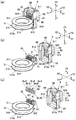
図1は、本発明の実施の形態1に係るモータの全体構成を示す説明図であり、図1(a)、(b)は各々、モータを出力軸が突出している出力側(Z2側)からみた斜視図、およびその分解斜視図である。図2は、本発明の実施の形態1に係るモータを出力軸が突出している側とは反対側(Z1側)からみた斜視図である。
[Embodiment 1]
FIG. 1 is an explanatory diagram showing the overall configuration of a motor according to
図1に示すように、本形態のモータ1は、ステッピングモータを用いたギヤードモータである。かかるモータ1において、モータ本体部1aは、有底円筒形の金属製のモータケース2、モータケース2の開口端を塞ぐ端板61、モータケース2の内側に配置された円筒状のステータ3、ステータ3の内側に配置されたロータ5、端板61に対してZ軸方向の一方側Z1に配置された地板65、地板65と端板61との間に配置された減速歯車列7、端板61からZ軸方向の他方側Z2に突出した出力軸50等を有している。
As shown in FIG. 1, the
ステータ3は、A相用の第1コイルを構成する第1コイル線36が巻回された第1コイルボビン31と、B相用の第2コイルを構成する第2コイル線37が巻回された第2コイルボビン32とを備えており、第1コイルボビン31と第2コイルボビン32とは、モータ軸線方向(Z軸方向)で重なるように配列されている。第1コイルボビン31は、モータ軸線方向のうち、出力軸50が突出する出力側(Z軸方向の他方側Z2)に配置され、第2コイルボビン32は、モータ軸線方向の反出力側(Z軸方向の一方側Z1)に配置されている。第1コイルボビン31は、樹脂成形品であり、第1コイル線36が巻回された円筒状胴部310と、円筒状胴部310の両端部で拡径する一対のフランジ部311、312とを備えている。第2コイルボビン32も、第1コイルボビン31と略同様な樹脂成形品であり、第2コイル線37が巻回された円筒状胴部320と、円筒状胴部320の両端部で拡径する一対のフランジ部321、322とを備えている。
The
ステータ3においては、第1コイルボビン31のフランジ部311に重なるようにA相用の外ステータコア41が配置されており、第1コイルボビン31のフランジ部312に重なるようにA相用の内ステータコア42が配置されている。図示を一部省略するが、外ステータコア41および内ステータコア42では、フランジ状の円環部の内周縁からモータ軸線方向(Z軸方向)に向けて複数の極歯が屈曲しており、外ステータコア41の極歯と内ステータコア42の極歯は、第1コイルボビン31の内周面に沿って周方向に交互に配置されている。また、第2コイルボビン32のフランジ部321に重なるようにB相用の外ステータコア43が配置されており、第2コイルボビン32の出力側のフランジ部322に重なるようにB相用の内ステータコア44が配置されている。かかるB相用の外ステータコア43および内ステータコア44でも、A相用の外ステータコア41および内ステータコア42と同様、フランジ状の円環部の内周縁からモータ軸線方向に複数の極歯が屈曲しており、外ステータコア43の極歯と内ステータコア44の極歯は、第2コイルボビン32の内周面に沿って周方向に交互に配置されている。
In the
かかる構成のステータ3の内側にはロータ5が配置されている。ロータ5は、モータ軸線方向(Z軸方向)に延在する回転軸51と、回転軸51の外周面に固着されたロータマグネット(図示せず)とを備えており、回転軸51は、支軸511によって回転可能に支持されている。ロータマグネットの外周面は、ステータ3の内周面で配列する極歯と対向しており、ロータマグネットの外周面では、S極とN極とが周方向で交互に配列されている。回転軸51の出力側端部の外周面には歯車510が形成されている。
A rotor 5 is disposed inside the
ステータ3の出力側端面には、円環状の地板65が重ねて配置されており、かかる地板65では、Z軸方向の他方側Z2に向けて2本の支持板部657が突出している。支持板部657は端板61の穴617との連結用である。また、地板65の中央には回転軸51を突出させる中央穴650が形成されている。
An
端板61には、地板65の中央穴650と対向する位置に支軸511を保持する軸受69が構成されており、軸受69の周りには、計4個の軸穴611、612、613、614が形成されている。なお、回転軸51の支軸511の反出力側端部は、モータケース2の底部22中央に形成された軸受(図示せず)に保持されている。
The
端板61には円形の貫通穴615が形成されており、かかる貫通穴615は、出力軸50の出力側端部を突出させている。貫通穴615の周りには、出力軸50を回転可能に支持する円筒部616が形成されている。地板65には端板61の軸穴611、612、613、614と対向する位置に軸穴が形成されており、かかる軸穴を利用して、地板65と端板61との間には、減速歯車列7を構成する第1歯車71、第2歯車72、第3歯車73および第4歯車74の支軸が保持されている。また、端板61には、相対向する両側からモータ機器への取り付け部となる2つの突部618が形成されている。
A circular through
このように構成したモータ1では、モータ本体部1aの第1コイル線36および第2コイル線37に給電する必要がある。かかる給電を行うために、本形態のモータ1では、第1コイルボビン31のフランジ部311のY軸方向の他方側Y2(径方向外側)に端子台35が形成されている。また、端子台35には、計5本の端子ピン8(端子ピン8a、8b、8c、8d、8e)が保持されており、端子ピン8に第1コイル線36および第2コイル線37の端部が接続されている。
In the
また、モータ本体部1aには、端子台35をY軸方向の他方側Y2(径方向外側)で覆うように樹脂製のカバー9が取り付けられている。本形態では、モータケース2に切り欠き229が形成されている一方、カバー9の周方向の両側にはフック99が形成されており、フック99が切り欠き229の内側から進入してモータケース2に係合することにより、モータケース2にカバー9が取り付けられている。また、端板61には2つの穴619が形成されている一方、カバー9には、Z軸方向の他方側Z2に向けて突出した突起98が形成されている。従って、フック99をモータケース2に係合させる際、突起98を穴619に嵌めることにより、モータ本体部1aの所定位置にカバー9を固定することができる。
Further, a
このようにしてカバー9を設けると、図2に示すように、モータ本体部1aのY軸方向の他方側Y2(径方向外側)には、カバー9によってZ軸方向の一方側Z1に向けて開口するコネクタ挿入部90が構成され、かかるコネクタ挿入部90には、5本の端子ピン8の各先端側が位置することになる。
When the
(端子ピン8および端子台35の詳細構成)
図3は、本発明の実施の形態1に係るモータ1の端子台35等を径方向外側(Y軸方向の他方側Y2)からみた説明図であり、図3(a)、(b)、(c)は、端子台35に対してカバー9を設けた状態の斜視図、端子台35からカバー9を外した状態の斜視図、および端子台35に端子ピン8を取り付ける前の状態の斜視図である。図4は、本発明の実施の形態1に係るモータ1の端子台35等を径方向内側(Y軸方向の一方側Y1)からみた説明図であり、図4(a)、(b)、(c)は、端子台35に対してカバー9を設けた状態の斜視図、端子台35からカバー9を外した状態の斜視図、および端子台35に端子ピン8を取り付ける前の状態の斜視図である。
(Detailed configuration of
FIG. 3 is an explanatory view of the
図3および図4に示すように、5本の端子ピン8はいずれも、コネクタ挿入部90の内側でZ軸方向の一方側Z1に延在する接続部分80を有しており、かかる接続部分80にコネクタ(図示せず)が接続される。本形態において、5本の端子ピン8はいずれも、1本の金属ピンを屈曲させた構造を有しており、端子台35から径方向外側に延在する第1部分81と、第1部分81の先端から接続部分80としてZ軸方向の一方側Z1に屈曲してZ軸方向の一方側Z1に延在する第2部分82とを有している。このため、5本の端子ピン8はいずれにおいても、第1部分81と第2部分82との間には、90°に屈曲した屈曲部分86が形成されている。また、5本の端子ピン8はいずれも、第1部分81の第2部分82が位置する側とは反対側の端部でZ軸方向の他方側Z2に屈曲してZ軸方向の他方側Z2に斜めに延在する第3部分83を有しており、第1部分81と第3部分83との間には、90°以下の角度で屈曲した屈曲部分87が形成されている。かかる構成の端子ピン8において、第3部分83には、第1コイル線36および第2コイル線37の端部が接続される。ここで、5本の端子ピン8のうち、最もX軸方向の一方側に位置する端子ピン8eは、他の端子ピン8a、8b、8c、8dに比して第1部分81が短い。このため、5本の端子ピン8の屈曲部分86は、X軸方向に一列に並んでいるが、端子ピン8eの屈曲部分87は、他の端子ピン8a、8b、8c、8dの屈曲部分に比して径方向外側(Y軸方向の他方側Y2)に位置する。かかる端子ピン8eはコモン用である。
As shown in FIGS. 3 and 4, each of the five
本形態において、端子台35は、第1コイルボビン31のフランジ部311のY軸方向の他方側Y2(径方向外側)にZ軸方向の他方側Z2に突出した肉厚部分として形成されており、図1(b)に示すモータケース2の切り欠き229の内側のZ軸方向の他方側Z2に位置する。また、端子台35には、複数箇所で折れ曲がった5本の端子ピン8の第1部分81が保持されている。かかる構成は、第1コイルボビン31を樹脂成形する際、5本の端子ピン8を直線的に延在した状態で一体成形し、しかる後に、5本の端子ピン8に折り曲げ加工することによって形成することができる。また、第1コイルボビン31を樹脂成形する際、端子ピン8の第1部分81を保持する穴を形成しておき、かかる穴に5本の端子ピン8を直線的に延在した状態で挿入し、しかる後に、5本の端子ピン8に折り曲げ加工することによっても形成することができる。
In this embodiment, the
端子台35の径方向内側の面では、端子ピン8の折り曲げ部分87が位置する部分が溝状凹部352になっており、溝状凹部352内に折り曲げ部分87が位置する。このため、端子ピン8の折り曲げ部分87は、端子台35の径方向内側の面から突出していない。また、端子台35の径方向内側の面には、端子ピン8aと端子ピン8bとの間、端子ピン8cと端子ピン8dとの間、および端子ピン8dと端子ピン8eの間に溝351が形成されており、かかる溝351は、端子台35のZ軸方向の他方側Z2の面まで形成されている。
On the radially inner surface of the
なお、第1コイルボビン31のフランジ部312のZ軸方向の一方側Z1に形成されている突起312aは、図1を参照して説明した内ステータコア42との位置決め用である。
The
(カバー9の詳細構成)
図5は、本発明の実施の形態1に係るモータ1のカバー9で端子ピン8を覆った状態を示す説明図であり、図5(a)、(b)、(c)は、カバー9を径方向内側(Y軸方向の一方側Y1)からみた斜視図、カバー9を径方向内側(Y軸方向の一方側Y1)からみた正面図、およびカバー9をZ軸方向の一方側Z1からみた底面図である。図6は、本発明の実施の形態1に係るモータ1のカバー9単独の説明図であり、図6(a)、(b)、(c)は、カバー9を径方向内側からみた斜視図、カバー9を径方向内側からみた正面図、およびカバー9をZ軸方向の一方側Z1からみた底面図である。
(Detailed configuration of cover 9)
FIG. 5 is an explanatory diagram illustrating a state in which the
図3および図4に示すように、カバー9は、端子台35が配置されたモータケース2の切り欠き229(図1(b)参照)の外縁に被さる矩形の枠部91と、枠部91より径方向外側(Y軸方向の他方側Y2)で枠部91のZ軸方向の他方側Z2を覆うコネクタハウジング92と、コネクタハウジング92よりZ軸方向の一方側Z1で枠部91の径方向外側(Y軸方向の他方側Y2)を覆う背板部93とを有している。このため、カバー9は、コネクタハウジング92に対して端子台35が位置する側が開放状態にある。
As shown in FIGS. 3 and 4, the
ここで、コネクタハウジング92は、背板部93より径方向外側(Y軸方向の他方側Y2)に位置しており、コネクタハウジング92は、Z軸方向の一方側Z1に向けて開口するコネクタ挿入部90を構成している。
Here, the
枠部91を構成する4つの辺部分911、912、913、914のうち、Z軸方向の他方側Z2に位置する辺部分911には突起98が形成され、周方向(X軸方向)の両側に位置する辺部分913、914にはフック99が形成されている。また、Z軸方向の一方側Z1に位置する辺部分912には、モータケース2の外周面に当接する円弧部912aが形成されている。
Of the four
図5および図6に示すように、コネクタ挿入部90には、端子台35から延在した端子ピン8の第2部分82(接続部分80)が位置しており、かかる第2部分82は、Z軸方向の一方側Z1からみたとき、コネクタハウジング92の径方向内側の面および背板部93の径方向外側の面から離間している。また、5本の端子ピン8は、端子台35の側からコネクタ挿入部90に延在し、コネクタ挿入部90では、隣り合う端子ピン8同士は、X軸方向で所定の隙間を介して直線的に並んでいる。
As shown in FIGS. 5 and 6, the
(端子ピン8の傾き防止用の凸部95の構成)
本形態では、カバー9には、カバー9の内面で突出して、端子ピン8の第2部分82の根元側を第1部分81の延在方向(Y軸方向)および第2部分82の延在方向(Z軸方向)の双方に対して直交する方向(X軸方向)の両側から支持する凸部95が設けられている。
(Configuration of the
In this embodiment, the
より具体的には、コネクタハウジング92の内面92aには、Z軸方向の略中央位置から一方側Z1に、端子ピン8の第2部分82に対して第1部分81が延在している側とは反対側(Y軸方向の他方側Y2)に第1壁部92cが形成されている。また、コネクタハウジング92の内面92aには、Z軸方向の略中央位置にX軸方向に延在する断面矩形のリブ状突起925が形成されており、かかるリブ状突起925のZ軸方向の一方側Z1の面によって、コネクタハウジング92の内面92aには、端子ピン8の第1部分81に対して第2部分82が延在している側とは反対側(Z軸方向の他方側Z2)に第2壁部925aが形成されている。ここで、第1壁部92cと第2壁部925aとの角部分92eは、テーパ面あるいはR面になっているとともに、かかる角部分92eには、計4つの凸部95が形成されている。
More specifically, on the
このため、端子ピン8bの屈曲部分86は、両側の凸部95によってX軸方向の両側から支持されており、端子ピン8cの屈曲部分86は、両側の凸部95によってX軸方向の両側から支持されており、端子ピン8dの屈曲部分86は、両側の凸部95によってX軸方向の両側から支持されている。また、端子ピン8aの屈曲部分86は、X軸方向の他方側X2で辺部分913の内面から突出した凸状部分で支持され、X軸方向の一方側X1では凸部95によって支持されている。また、端子ピン8eの屈曲部分86は、X軸方向の一方側X1で辺部分914の内面から突出した凸状部分で支持され、X軸方向の他方側X2では凸部95によって支持されている。
Therefore, the
本形態において、凸部95は、第1壁部92cおよび第2壁部925aに繋がった状態で突出している。また、凸部95は、YZ断面が台形形状であり、第2部分82の延在方向(Z軸方向の一方側Z1)に向く端面951と、端子台35が位置する側(Y軸方向の一方側Y1)および第2部分82が延在している側(Z軸方向の一方側Z1)に対して斜めに向いた斜面952とを備えている。このため、凸部95は、端子ピン8の屈曲部分86が位置する側(第2壁部925aの側)の部分の厚さ(Y軸方向の寸法)が大で、Z軸方向の一方側Z1に向かうにしたがって厚さ(Y軸方向の寸法)が小になって、第2部分82の延在方向(Z軸方向の一方側Z1)に向く端面951を構成している。このため、端子ピン8を凸部95間に挿入しやすい。
In this embodiment, the
(本形態の主な効果)
以上説明したように、本形態のモータ1において、カバー9のコネクタハウジング92には、端子ピン8においてコネクタ挿入部90でZ軸方向の一方側Z1に向けて延在する第2部分82(コネクタとの接続部分80)の根元側を第1部分81の延在方向(Y軸方向)および第2部分82の延在方向(Z軸方向)の双方に対して直交する方向(X軸方向)の両側から支持する凸部95が設けられている。このため、端子台35とカバー9との間に隔壁があるか否かにかかわらず、第2部分82の根元側をX軸方向の両側から凸部95によって支持することができる。また、凸部95は、第2部分82の根元側を保持しているため、第2部分82の変位を効果的に抑制することができる。それ故、コネクタ挿入部90にコネクタを挿入する際、端子ピン8の第2部分82がX軸方向に傾いて、コネクタを挿入できないという事態を回避することができる。
(Main effects of this form)
As described above, in the
特に本形態では、凸部95が第2部分82の根元側のうち、第1部分81と第2部分82との屈曲部分86を支持している。従って、第2部分82の根元側を確実に支持することができるので、第2部分82の変位を効果的に抑制することができる。また、カバー9を端子台35の外側を覆うように設ける際、凸部95の間に端子ピン8の屈曲部分86を挿入すればよいので、第2部分82をコネクタ挿入部90まで延在させやすい。
In particular, in this embodiment, the
また、カバー9は、凸部95が形成されている部分(コネクタハウジング92)に対して端子台35が位置する側が開放状態にある。このため、カバー9を端子台35の外側を覆うように設ける際、端子ピン8が邪魔にならないので、カバー9を設けるのが容易である。
Further, the
また、凸部95は、コネクタに対するストッパとして機能するため、コネクタの挿入が容易である。特に本形態おいて、凸部95は、第2部分82の延在方向(Z軸方向の一方側Z1)に向く端面951を備えているため、凸部95の端面951は、コネクタに対するストッパとして機能する。
Moreover, since the
また、凸部95は、端子台35が位置する側および第2部分82の延在方向に対して斜めに向いた斜面952を備えている。このため、カバー9を端子台35の外側を覆うように設ける際、凸部95の間に端子ピン8を挿入しやすい。
Moreover, the
さらに、カバー9のコネクタハウジング92の内面92aには、第2部分82に対して第1部分81が延在している側とは反対側に位置する第1壁部92cと、第1部分81に対して第2部分82が延在している側とは反対側に位置する第2壁部925aとが設けられ、凸部95は、第1壁部92cと第2壁部925aとの角部分92eに設けられている。このため、カバー9を端子台35の外側を覆うように設ける際、第1壁部92cおよび第2壁部925aが端子ピン8に対するガイドや受け部として機能する。それ故、カバー9を端子台35の外側を覆うように設ける際、第2部分82をコネクタ挿入部90まで延在させやすい。
Furthermore, on the
[実施の形態2]
図7は、本発明の実施の形態2に係るモータ1のカバー9単独の説明図であり、図7(a)、(b)、(c)は、カバー9を径方向内側からみた斜視図、カバー9を径方向内側からみた正面図、およびカバー9をZ軸方向の一方側Z1からみた底面図である。なお、本形態の基本的な構成は、実施の形態1と同様であるため、対応する部分には同一の符号を付して図示し、それらの説明を省略する。
[Embodiment 2]
FIG. 7 is an explanatory view of the
図7に示すように、本形態でも、カバー9には、カバー9の内面で突出して、端子ピン8の第2部分82(コネクタとの接続部分80)の根元側(屈曲部分86)を第1部分81の延在方向(Y軸方向)および第2部分82の延在方向(Z軸方向)の双方に対して直交する方向(X軸)の両側から支持する凸部95が設けられている。より具体的には、コネクタハウジング92の内面92aには、第1壁部92cと第2壁部925aとの角部分92eに計4つの凸部95が形成され、かかる凸部95は、第1壁部92cおよび第2壁部925aに繋がった状態で突出している。ここで、凸部95は、YZ断面が三角形状であり、端子台35が位置する側(Y軸方向の一方側Y1)および第2部分82が延在している側(Z軸方向の一方側Z1)に対して斜めに向いた斜面952を備えている。
As shown in FIG. 7, also in this embodiment, the
このように構成したモータ1においても、実施の形態1と同様、第2部分82(コネクタとの接続部分80)の根元側をX軸方向の両側から凸部95によって支持することができるため、第2部分82の変位を効果的に抑制することができる。それ故、コネクタ挿入部90にコネクタを挿入する際、端子ピン8の第2部分82がX軸方向に傾いて、コネクタを挿入できないという事態を回避することができる等、実施の形態1と同様な効果を奏する。また、本形態でも、実施の形態1と同様、凸部95は、端子台35が位置する側および第2部分82の延在方向に対して斜めに向いた斜面952を備えている。このため、カバー9を端子台35の外側を覆うように設ける際、凸部95の間に端子ピン8を挿入しやすい。
In the
[実施の形態3]
図8は、本発明の実施の形態3に係るモータ1のカバー9単独の説明図であり、図8(a)、(b)、(c)は、カバー9を径方向内側からみた斜視図、カバー9を径方向内側からみた正面図、およびカバー9をZ軸方向の一方側Z1からみた底面図である。なお、本形態の基本的な構成は、実施の形態1と同様であるため、対応する部分には同一の符号を付して図示し、それらの説明を省略する。
[Embodiment 3]
FIG. 8 is an explanatory diagram of the
図8に示すように、本形態でも、カバー9には、カバー9の内面で突出して、端子ピン8の第2部分82(コネクタとの接続部分80)の根元側(屈曲部分86)を第1部分81の延在方向(Y軸方向)および第2部分82の延在方向(Z軸方向)の双方に対して直交する方向(X軸)の両側から支持する凸部95が設けられている。より具体的には、コネクタハウジング92の内面92aには、第1壁部92cと第2壁部925aとの角部分92eに計4つの凸部95が形成されている。
As shown in FIG. 8, also in this embodiment, the
ここで、凸部95は、第1壁部92cから離間する位置で第2壁部925aから第2部分82が延在している側(Z軸方向の一方側Z1)に向けて丸棒状に突出している。このため、凸部95は、第2部分82の延在方向(Z軸方向の一方側Z1)に向く端面951を備えている。
Here, the
このように構成したモータ1においても、実施の形態1と同様、第2部分82(コネクタとの接続部分80)の根元側をX軸方向の両側から凸部95によって支持することができるため、第2部分82の変位を効果的に抑制することができる。それ故、コネクタ挿入部90にコネクタを挿入する際、端子ピン8の第2部分82がX軸方向に傾いて、コネクタを挿入できないという事態を回避することができる等、実施の形態1と同様な効果を奏する。また、本形態でも、実施の形態1と同様、凸部95は、第2部分82の延在方向(Z軸方向の一方側Z1)に向く端面951を備えているため、凸部95の端面951は、コネクタに対するストッパとして確実に機能する。
In the
なお、本形態では、凸部95を丸棒状に突出させたが、角棒状に突出させてもよい。
In this embodiment, the
[実施の形態4]
図9は、本発明の実施の形態4に係るモータ1のカバー9単独の説明図であり、図9(a)、(b)、(c)は、カバー9を径方向内側からみた斜視図、カバー9を径方向内側からみた正面図、およびカバー9をZ軸方向の一方側Z1からみた底面図である。なお、本形態の基本的な構成は、実施の形態1と同様であるため、対応する部分には同一の符号を付して図示し、それらの説明を省略する。
[Embodiment 4]
FIG. 9 is an explanatory view of the
図9に示すように、本形態でも、カバー9には、カバー9の内面で突出して、端子ピン8の第2部分82(コネクタとの接続部分80)の根元側(屈曲部分86)を第1部分81の延在方向(Y軸方向)および第2部分82の延在方向(Z軸方向)の双方に対して直交する方向(X軸)の両側から支持する凸部95が設けられている。より具体的には、コネクタハウジング92の内面92aには、第1壁部92cと第2壁部925aとの角部分92eに計4つの凸部95が形成されている。
As shown in FIG. 9, also in this embodiment, the
ここで、凸部95は、第2壁部925aから離間する位置で第1壁部92cから端子台35(Y軸方向の一方側Y1)に向けて丸棒状に突出している。
Here, the
このように構成したモータ1においても、実施の形態1と同様、第2部分82(コネクタとの接続部分80)の根元側をX軸方向の両側から凸部95によって支持することができるため、第2部分82の変位を効果的に抑制することができる。それ故、コネクタ挿入部90にコネクタを挿入する際、端子ピン8の第2部分82がX軸方向に傾いて、コネクタを挿入できないという事態を回避することができる等、実施の形態1と同様な効果を奏する。
In the
なお、本形態では、凸部95を丸棒状に突出させたが、角棒状に突出させてもよい。
In this embodiment, the
[他の実施の形態]
上記実施の形態では、1本の金属ピンを屈曲させて、端子台35から径方向外側に延在する第1部分81と、第1部分81の先端からZ軸方向の一方側Z1に延在する第2部分82(接続部分80)とを有する端子ピン8を構成したが、第2壁部925aに端子ピン8の根元側が保持され、第2壁部925aから端子ピン8の接続部分80がZ軸方向の一方側Z1に延在しているモータ1に本発明を適用してもよい。この場合、例えば、接続部分80と別体の端子が端子台35に保持されてコイル線が巻回された構造となる。
[Other embodiments]
In the above-described embodiment, one metal pin is bent, the
上記実施の形態では、コネクタ挿入部90で端子ピン8の第2部分82が一列に整列していたが、コネクタ挿入部90で端子ピン8の第2部分82が列状に配置されていない場合に本発明を適用してもよい。また、上記実施の形態では、端子ピン8の数が5本であったが、それ以外の本数のモータに本発明を適用してもよい。
In the above embodiment, the second portions 82 of the
まは、本発明は、ステッピングモータに限らず、コネクタを利用するモータであれば、他の種類のモータに適用してもよい。 Alternatively, the present invention is not limited to a stepping motor, and may be applied to other types of motors as long as the motor uses a connector.
1 モータ
2 モータケース
3 ステータ
5 ロータ
8 端子ピン
9 カバー
35 端子台
80 接続部分(コネクタとの接続部分)
81 端子ピンの第1部分
82 端子ピンの第2部分(コネクタとの接続部分)
83 端子ピンの第3部分
86、87 端子ピンの屈曲部分
90 コネクタ挿入部
92 コネクタハウジング
92a コネクタハウジングの内面(カバーの内面)
92c 第1壁部
95 凸部
925a 第2壁部
951 端面
952 斜面
DESCRIPTION OF
81 First portion of terminal pin 82 Second portion of terminal pin (connecting portion with connector)
83 Terminal pin
92c
Claims (10)
前記ステータを構成するコイル線が巻回されるコイルボビンの径方向外側に設けられ、前記モータケースの切り欠き内に位置する端子台と、
該端子台に保持され、前記コイル線に給電するための複数の端子ピンと、
前記端子台を径方向外側で覆うように前記モータ本体部に取り付けられ、モータ軸線方向の一方側に向けて開口するコネクタ挿入部を構成するカバーと、
を有し、
前記カバーは、前記切り欠きの外縁に被さる枠部と、該枠部の前記モータ軸線方向の他方側を径方向外側から覆うコネクタハウジングと、前記コネクタハウジングより前記モータ軸線方向の前記一方側で前記枠部を径方向外側から覆う背板部と、を備え、
前記コネクタハウジングは、前記背板部より径方向外側に形成されて径方向内側に前記コネクタ挿入部を構成しており、
前記複数の端子ピンは各々、前記コネクタハウジングの内側で前記端子台から径方向外側に延在する第1部分と、前記端子台から径方向外側に離間する前記第1部分の先端で前記モータ軸線方向の前記一方側に折れ曲がって前記コネクタ挿入部で延在する第2部分と、を備え、
前記第2部分は、前記モータ軸線方向の前記一方側からみたとき、前記コネクタハウジングの径方向内側の面、および前記背板部の径方向外側の面から離間しており、
前記カバーには、前記コネクタハウジングの内面で突出して前記複数の端子ピンの各々の前記第2部分の根元側を前記第1部分の延在方向および前記第2部分の延在方向の双方に対して直交する方向の両側から支持する凸部が設けられていることを特徴とするモータ。 A motor main body comprising a rotor , a stator, and a motor case, wherein the rotor and the stator are disposed inside the motor case ;
A terminal block provided on a radially outer side of a coil bobbin around which a coil wire constituting the stator is wound, and located in a notch of the motor case ;
A plurality of terminal pins held by the terminal block for supplying power to the coil wire ;
A cover that is attached to the motor main body so as to cover the terminal block outside in the radial direction, and that constitutes a connector insertion portion that opens toward one side in the motor axial direction,
Have
The cover includes a frame portion that covers an outer edge of the notch, a connector housing that covers the other side of the frame portion in the motor axial direction from the outside in the radial direction, and the one side of the motor housing in the motor axial direction from the connector housing. A back plate portion covering the frame portion from the outside in the radial direction,
The connector housing is formed on the radially outer side than the back plate portion and constitutes the connector insertion portion on the radially inner side,
Each of the plurality of terminal pins includes a first portion extending radially outward from the terminal block inside the connector housing, and a motor axis at a tip of the first portion spaced radially outward from the terminal block. A second portion that bends to the one side of the direction and extends at the connector insertion portion,
The second portion is separated from a radially inner surface of the connector housing and a radially outer surface of the back plate portion when viewed from the one side in the motor axial direction,
The cover protrudes from the inner surface of the connector housing, and the base side of the second portion of each of the plurality of terminal pins is directed to both the extending direction of the first portion and the extending direction of the second portion. And a convex portion that is supported from both sides in a direction orthogonal to each other .
前記凸部は、前記第1壁部と前記第2壁部との角部分に設けられていることを特徴とする請求項1乃至5の何れか一項に記載のモータ。 The inner surface of the cover has a first wall located on the opposite side of the second portion from the side on which the first portion extends, and the second portion with respect to the first portion. A second wall located on the opposite side of the side from which the
The motor according to any one of claims 1 to 5 , wherein the convex portion is provided at a corner portion between the first wall portion and the second wall portion .
前記コイル線は、前記第3部分に接続されていることを特徴とする請求項1乃至9の何れか一項に記載のモータ。 Each of the plurality of terminal pins includes a third portion bent in the motor axial direction at an end of the first portion opposite to the side where the second portion is located.
The coil wire, motor according to any one of claims 1 to 9, characterized in that it is connected to the third portion.
Priority Applications (3)
| Application Number | Priority Date | Filing Date | Title |
|---|---|---|---|
| JP2013080255A JP6188385B2 (en) | 2013-04-08 | 2013-04-08 | motor |
| CN201420152971.3U CN203761168U (en) | 2013-04-08 | 2014-03-31 | Motor |
| CN201410125584.5A CN104104172A (en) | 2013-04-08 | 2014-03-31 | Motor |
Applications Claiming Priority (1)
| Application Number | Priority Date | Filing Date | Title |
|---|---|---|---|
| JP2013080255A JP6188385B2 (en) | 2013-04-08 | 2013-04-08 | motor |
Publications (3)
| Publication Number | Publication Date |
|---|---|
| JP2014204595A JP2014204595A (en) | 2014-10-27 |
| JP2014204595A5 JP2014204595A5 (en) | 2016-04-21 |
| JP6188385B2 true JP6188385B2 (en) | 2017-08-30 |
Family
ID=51256404
Family Applications (1)
| Application Number | Title | Priority Date | Filing Date |
|---|---|---|---|
| JP2013080255A Expired - Fee Related JP6188385B2 (en) | 2013-04-08 | 2013-04-08 | motor |
Country Status (2)
| Country | Link |
|---|---|
| JP (1) | JP6188385B2 (en) |
| CN (2) | CN203761168U (en) |
Families Citing this family (8)
| Publication number | Priority date | Publication date | Assignee | Title |
|---|---|---|---|---|
| JP6188385B2 (en) * | 2013-04-08 | 2017-08-30 | 日本電産サンキョー株式会社 | motor |
| FR3030150B1 (en) * | 2014-12-11 | 2018-03-16 | Valeo Systemes Thermiques | ACTUATOR WITH REDUCED SIZE, WITH INTEGRATED BLOCKING OF THE MOTOR IN RELATION TO THE HOUSING |
| JP6673672B2 (en) * | 2015-11-09 | 2020-03-25 | 株式会社デンソー | motor |
| JP2018026938A (en) * | 2016-08-09 | 2018-02-15 | 日本電産サンキョー株式会社 | Terminal part and motor and drain valve driving device |
| JP6887899B2 (en) * | 2017-07-05 | 2021-06-16 | 株式会社ミツバ | Manufacturing method of motor device |
| CN110034640B (en) * | 2018-01-12 | 2020-07-28 | 日本电产三协电子(东莞)有限公司 | Method for manufacturing motor |
| JP7072427B2 (en) * | 2018-03-30 | 2022-05-20 | 日本電産サンキョー株式会社 | motor |
| KR101917212B1 (en) * | 2018-05-02 | 2019-01-24 | 조영길 | A terminal block of motor |
Family Cites Families (10)
| Publication number | Priority date | Publication date | Assignee | Title |
|---|---|---|---|---|
| JPH02102674U (en) * | 1989-02-02 | 1990-08-15 | ||
| JP3096003B2 (en) * | 1996-05-21 | 2000-10-10 | 株式会社東富士製作所 | Stepping motor |
| FR2750812B1 (en) * | 1996-07-08 | 1999-04-02 | Valeo Systemes Dessuyage | GEAR GEAR WITH BLADE HOLDER PLATE |
| JP2010081685A (en) * | 2008-09-24 | 2010-04-08 | Nidec Sankyo Corp | Geared motor and method of manufacturing the same |
| JP5636170B2 (en) * | 2009-06-11 | 2014-12-03 | 日本電産サンキョー株式会社 | motor |
| JP2011124193A (en) * | 2009-12-14 | 2011-06-23 | Sumitomo Wiring Syst Ltd | Pedestal connector |
| JP2012134087A (en) * | 2010-12-24 | 2012-07-12 | Sumitomo Wiring Syst Ltd | Electrical connection box |
| JP5290345B2 (en) * | 2011-03-31 | 2013-09-18 | 株式会社小松製作所 | Generator motor and work machine |
| JP5539256B2 (en) * | 2011-04-14 | 2014-07-02 | 日立建機株式会社 | Electric motor |
| JP6188385B2 (en) * | 2013-04-08 | 2017-08-30 | 日本電産サンキョー株式会社 | motor |
-
2013
- 2013-04-08 JP JP2013080255A patent/JP6188385B2/en not_active Expired - Fee Related
-
2014
- 2014-03-31 CN CN201420152971.3U patent/CN203761168U/en not_active Expired - Fee Related
- 2014-03-31 CN CN201410125584.5A patent/CN104104172A/en active Pending
Also Published As
| Publication number | Publication date |
|---|---|
| JP2014204595A (en) | 2014-10-27 |
| CN203761168U (en) | 2014-08-06 |
| CN104104172A (en) | 2014-10-15 |
Similar Documents
| Publication | Publication Date | Title |
|---|---|---|
| JP6188385B2 (en) | motor | |
| US10673299B2 (en) | Step actuator | |
| JP6127794B2 (en) | Rotating electric machine stator | |
| JP2012075215A (en) | Stator | |
| JP2012075213A (en) | Stator | |
| JP5937651B2 (en) | motor | |
| JP2008035601A (en) | Rotating electric machine | |
| JP2008289325A (en) | Busbar unit mounting structure and stator | |
| WO2017082096A1 (en) | Motor | |
| JP2015082935A (en) | Motor and method for connecting winding to terminal pin in motor | |
| JP2023133515A (en) | motor | |
| JP5928904B2 (en) | Insulator, stator assembly, rotating electric machine, and wiring board | |
| JP2017034742A (en) | motor | |
| JP4646758B2 (en) | Motor manufacturing method and motor | |
| JP2012105372A (en) | Outer rotor type electric motor | |
| JP2019062688A (en) | motor | |
| JP6139203B2 (en) | Stepping motor | |
| CN211239499U (en) | Motor stator and winding frame thereof | |
| JP2018125898A (en) | Rotary electric machine | |
| JP2020054127A (en) | motor | |
| JP2019115151A (en) | motor | |
| JP2018117407A (en) | Coil bobbin, stepping motor, and pointer type display device | |
| JP6233217B2 (en) | Rotating electric machine stator | |
| JP2020137312A (en) | motor | |
| JP2019097231A (en) | Motor and coil bobbin |
Legal Events
| Date | Code | Title | Description |
|---|---|---|---|
| A521 | Written amendment |
Free format text: JAPANESE INTERMEDIATE CODE: A523 Effective date: 20160307 |
|
| A621 | Written request for application examination |
Free format text: JAPANESE INTERMEDIATE CODE: A621 Effective date: 20160307 |
|
| A977 | Report on retrieval |
Free format text: JAPANESE INTERMEDIATE CODE: A971007 Effective date: 20161227 |
|
| A131 | Notification of reasons for refusal |
Free format text: JAPANESE INTERMEDIATE CODE: A131 Effective date: 20170104 |
|
| A521 | Written amendment |
Free format text: JAPANESE INTERMEDIATE CODE: A523 Effective date: 20170303 |
|
| TRDD | Decision of grant or rejection written | ||
| A01 | Written decision to grant a patent or to grant a registration (utility model) |
Free format text: JAPANESE INTERMEDIATE CODE: A01 Effective date: 20170725 |
|
| A61 | First payment of annual fees (during grant procedure) |
Free format text: JAPANESE INTERMEDIATE CODE: A61 Effective date: 20170801 |
|
| R150 | Certificate of patent or registration of utility model |
Ref document number: 6188385 Country of ref document: JP Free format text: JAPANESE INTERMEDIATE CODE: R150 |
|
| LAPS | Cancellation because of no payment of annual fees |