JP2012105372A - Outer rotor type electric motor - Google Patents

Outer rotor type electric motor Download PDF

Info

Publication number
JP2012105372A
JP2012105372A JP2010248946A JP2010248946A JP2012105372A JP 2012105372 A JP2012105372 A JP 2012105372A JP 2010248946 A JP2010248946 A JP 2010248946A JP 2010248946 A JP2010248946 A JP 2010248946A JP 2012105372 A JP2012105372 A JP 2012105372A
Authority
JP
Japan
Prior art keywords
stator core
insulator
stator
coil
electric motor
Prior art date
Legal status (The legal status is an assumption and is not a legal conclusion. Google has not performed a legal analysis and makes no representation as to the accuracy of the status listed.)
Pending
Application number
JP2010248946A
Other languages
Japanese (ja)
Inventor
Masayuki Hayakawa
真幸 早川
Takeshi Kitaori
健 北折
Current Assignee (The listed assignees may be inaccurate. Google has not performed a legal analysis and makes no representation or warranty as to the accuracy of the list.)
Honda Motor Co Ltd
Original Assignee
Honda Motor Co Ltd
Priority date (The priority date is an assumption and is not a legal conclusion. Google has not performed a legal analysis and makes no representation as to the accuracy of the date listed.)
Filing date
Publication date
Application filed by Honda Motor Co Ltd filed Critical Honda Motor Co Ltd
Priority to JP2010248946A priority Critical patent/JP2012105372A/en
Publication of JP2012105372A publication Critical patent/JP2012105372A/en
Pending legal-status Critical Current

Links

Images

Classifications

    • YGENERAL TAGGING OF NEW TECHNOLOGICAL DEVELOPMENTS; GENERAL TAGGING OF CROSS-SECTIONAL TECHNOLOGIES SPANNING OVER SEVERAL SECTIONS OF THE IPC; TECHNICAL SUBJECTS COVERED BY FORMER USPC CROSS-REFERENCE ART COLLECTIONS [XRACs] AND DIGESTS
    • Y02TECHNOLOGIES OR APPLICATIONS FOR MITIGATION OR ADAPTATION AGAINST CLIMATE CHANGE
    • Y02TCLIMATE CHANGE MITIGATION TECHNOLOGIES RELATED TO TRANSPORTATION
    • Y02T10/00Road transport of goods or passengers
    • Y02T10/60Other road transportation technologies with climate change mitigation effect
    • Y02T10/64Electric machine technologies in electromobility

Abstract

PROBLEM TO BE SOLVED: To provide an outer rotor type electric motor capable of preventing an insulator from getting out of teeth of a stator and surely preventing the contact of the insulator and a rotor.SOLUTION: An outer rotor type electric motor 1 includes: a stator 10 including a stator core 11 provided with a plurality of teeth 11b arranged and radially projected at a prescribed interval in a circumferential direction, a plurality of insulators 12 arranged on the teeth 11b, and a plurality of coils 13 formed by winding a winding wire around the outer periphery of the insulators 12; and an annular rotor 6 arranged on the radial direction outer side of the stator 10. An extension part 38 extended to the radiation direction inner side of the stator core 11 is formed on each insulator 12, and the extension part 38 has a hook-like claw part 38a to be engaged with the stator core 11.

Description

本発明は、外転型の電動機に関し、特に、ハイブリッド自動車や電気自動車に搭載することが可能な外転型の電動機に関する。   The present invention relates to an abduction type electric motor, and more particularly to an abduction type electric motor that can be mounted on a hybrid vehicle or an electric vehicle.

従来の外転型の電動機に用いられるステータとしては、隣接するティースの間のスロットの底付近から鋼板の積層方向外側に起立する爪を最外層の鋼板に形成し、渡り線をこの爪の外周側に通して、渡り線がステータの内径側に移動してステータの取付け座面に入るのを防止して、組立性の向上を図ったものが知られている(例えば、特許文献1参照)。   As a stator used in a conventional abduction type electric motor, a claw standing on the outer side in the laminating direction of the steel sheet from the vicinity of the slot between adjacent teeth is formed on the outermost steel sheet, and a connecting wire is formed on the outer periphery of the claw. It is known that the crossover wire is moved to the inner diameter side of the stator and prevented from entering the mounting seat surface of the stator to improve the assemblability (for example, see Patent Document 1). .

しかしながら、特許文献1に記載のステータは、外周部に周方向突起が形成されたティースに巻線が巻回されているため、ティースと巻線との電気絶縁が十分ではなかった。そこで、周方向突起の無いステータコアのティースに、巻線が巻回された樹脂製のインシュレータをステータコアの径方向外側から挿入するステータを利用することが考えられる。   However, in the stator described in Patent Document 1, since the winding is wound around the tooth having the circumferential protrusion formed on the outer peripheral portion, the electrical insulation between the tooth and the winding is not sufficient. Therefore, it is conceivable to use a stator in which a resin insulator around which a winding is wound is inserted into the teeth of the stator core having no circumferential protrusion from the outside in the radial direction of the stator core.

特開2002−315250号公報JP 2002-315250 A

しかし、インシュレータを用いたステータにおいては、同相のコイル同士を接続している渡り部のスプリングバックによって、インシュレータがステータの径方向外側に押し出される傾向があり、インシュレータとロータが接触する可能性があった。   However, in a stator using an insulator, the insulator tends to be pushed outward in the radial direction of the stator by the springback of the connecting portion connecting the coils of the same phase, and there is a possibility that the insulator and the rotor come into contact with each other. It was.

本発明は、前述した事情に鑑みてなされたものであり、その目的は、インシュレータがステータのティースから抜け出すことを防止して、インシュレータとロータとの接触を確実に防止することができる外転型の電動機を提供することにある。   The present invention has been made in view of the above-described circumstances, and an object thereof is to prevent the insulator from coming out of the stator teeth, and to reliably prevent contact between the insulator and the rotor. It is to provide an electric motor.

上記目的を達成するために、請求項1に係る発明は、周方向に所定の間隔で配置され放射状に突出する複数のティース(例えば、後述の実施形態におけるティース11b)を有するステータコア(例えば、後述の実施形態におけるステータコア11)と、各ティースに配置される複数のインシュレータ(例えば、後述の実施形態におけるインシュレータ12)と、前記インシュレータの外周に巻線を巻回することで形成される複数のコイル(例えば、後述の実施形態におけるコイル13)と、を有するステータ(例えば、後述の実施形態におけるステータ10)と、前記ステータの径方向外側に配置される円環状のロータ(例えば、後述の実施形態におけるロータ6)と、を備える外転型の電動機であって、各インシュレータには、前記ステータコアの径方向内側に延出する延出部(例えば、後述の実施形態における延出部38)が形成され、前記延出部が、前記ステータコアと係合する鉤状爪部(例えば、後述の実施形態における鉤状爪部38a)を有することを特徴とする。   In order to achieve the above object, the invention according to claim 1 is a stator core (for example, described later) having a plurality of teeth (for example, teeth 11b in embodiments described later) that are arranged at predetermined intervals in the circumferential direction and project radially. Stator core 11) in the embodiment, a plurality of insulators (for example, an insulator 12 in the embodiment described later) disposed in each tooth, and a plurality of coils formed by winding a winding around the outer periphery of the insulator. (For example, a coil 13 in an embodiment described later), and an annular rotor (for example, an embodiment described later) disposed on the radially outer side of the stator. 6 is an abduction-type electric motor provided with each of the insulators. An extension portion (for example, an extension portion 38 in an embodiment described later) extending inward in the radial direction of the core is formed, and the extension portion engages with the stator core (for example, an after-mentioned pawl portion). It has the hook-shaped nail | claw part 38a) in embodiment.

請求項2に係る発明は、請求項1の構成に加えて、前記ステータコアが円環状の内周壁(例えば、後述の実施形態における内周壁11d)を有し、前記延出部が前記ステータコアの軸方向面に沿って延出し、前記鉤状爪部が、前記ステータコアの前記内周壁と係合することを特徴とする。   According to a second aspect of the invention, in addition to the configuration of the first aspect, the stator core has an annular inner peripheral wall (for example, an inner peripheral wall 11d in an embodiment described later), and the extending portion is a shaft of the stator core. It extends along a directional surface, and the hook-like claw portion engages with the inner peripheral wall of the stator core.

請求項3に係る発明は、請求項2の構成に加えて、前記鉤状爪部が前記延出部の周方向両端部に形成され、前記延出部の周方向両端部の間に切り欠き部(例えば、後述の実施形態における切り欠き部38b)が形成されることを特徴とする。   According to a third aspect of the present invention, in addition to the configuration of the second aspect, the hook-shaped claw portions are formed at both ends in the circumferential direction of the extension portion, and are notched between both ends in the circumferential direction of the extension portion. A part (for example, a notch part 38b in an embodiment described later) is formed.

請求項4に係る発明は、請求項1の構成に加えて、前記延出部が前記ティースの周方向面に沿って延出し、前記鉤状爪部が、前記ステータコアの隣り合うティース間に形成された凹部(例えば、後述の実施形態における凹部11e)と係合することを特徴とする。   According to a fourth aspect of the present invention, in addition to the configuration of the first aspect, the extending portion extends along a circumferential surface of the teeth, and the hook-shaped claw portion is formed between adjacent teeth of the stator core. It engages with the recessed part (for example, the recessed part 11e in embodiment mentioned later) made.

請求項1の発明によれば、インシュレータの延出部に形成された鉤状爪部がステータコアと係合するので、インシュレータがステータのティースから抜け出すことを防止して、インシュレータとロータとの接触を確実に防止することができる。   According to the first aspect of the present invention, since the hook-shaped claw portion formed in the extending portion of the insulator engages with the stator core, the insulator is prevented from coming out of the teeth of the stator, and the contact between the insulator and the rotor is prevented. It can be surely prevented.

請求項2の発明によれば、ステータコアの軸方向面に沿って延出する延出部に形成された鉤状爪部がステータコアの内周壁と係合するので、簡易な構造によりインシュレータをステータコアに固定することができる。   According to the invention of claim 2, since the hook-shaped claw portion formed on the extending portion extending along the axial direction surface of the stator core engages with the inner peripheral wall of the stator core, the insulator is attached to the stator core with a simple structure. Can be fixed.

請求項3の発明によれば、延出部の周方向両端部の間に切り欠き部が形成されることにより、ステータ固定用のボルトのための空間が残るので、全て同形状のインシュレータを用いることができ、製造が容易になる。   According to the invention of claim 3, since the notch is formed between both ends in the circumferential direction of the extending portion, a space for the bolt for fixing the stator remains, so that the insulator having the same shape is used. Can be manufactured easily.

請求項4の発明によれば、ティースの周方向面に沿って延出する延出部に形成された鉤状爪部が、ステータコアの隣り合うティース間に形成された凹部と係合するので、簡易な構造によりインシュレータをステータコアに固定することができる。また、全て同形状のインシュレータを用いることができ、製造が容易になる。   According to the invention of claim 4, since the hook-shaped claw portion formed on the extending portion extending along the circumferential surface of the tooth engages with the concave portion formed between adjacent teeth of the stator core, The insulator can be fixed to the stator core with a simple structure. Further, the insulator having the same shape can be used, and the manufacturing becomes easy.

本発明の第1実施形態に係る電動機の縦断面図である。It is a longitudinal section of the electric motor concerning a 1st embodiment of the present invention. 図1におけるステータの正面図である。It is a front view of the stator in FIG. 図2におけるステータコアの正面図である。It is a front view of the stator core in FIG. (a)は図1におけるインシュレータの斜視図であり、(b)は同じインシュレータの別方向から見た斜視図である。(A) is the perspective view of the insulator in FIG. 1, (b) is the perspective view seen from the other direction of the same insulator. (a)はインシュレータに巻線が巻回された第1のコイルの斜視図であり、(b)はインシュレータに巻線が巻回された第2のコイルの斜視図である。(A) is a perspective view of the 1st coil by which the coil | winding was wound by the insulator, (b) is a perspective view of the 2nd coil by which the coil | winding was wound by the insulator. コイル巻線の接合部を示す拡大斜視図である。It is an expansion perspective view which shows the junction part of a coil winding. 図4のインシュレータのステータコアへの固定状態を示す要部斜視図である。It is a principal part perspective view which shows the fixed state to the stator core of the insulator of FIG. 変形例に係るインシュレータの斜視図である。It is a perspective view of the insulator which concerns on a modification. 本発明の第2実施形態に係る電動機のステータの正面図である。It is a front view of the stator of the electric motor which concerns on 2nd Embodiment of this invention. 図9におけるステータコアの正面図である。FIG. 10 is a front view of the stator core in FIG. 9. 図9におけるインシュレータの斜視図である。It is a perspective view of the insulator in FIG. 図11におけるインシュレータのステータコアへの固定状態を示す要部断面図である。It is principal part sectional drawing which shows the fixed state to the stator core of the insulator in FIG.

以下、本発明の実施の形態を、添付図面に基づいて説明する。なお、図面は符号の向きに見るものとする。   Hereinafter, embodiments of the present invention will be described with reference to the accompanying drawings. The drawings are viewed in the direction of the reference numerals.

(第1実施形態)
まず、本発明の第1実施形態に係る外転型の電動機について、図1〜7を参照して説明する。図1に示すように、本実施形態の電動機は、3相8極対の外転型電動機1であり、軸心Oを中心として、モータハウジング2にボルト3により固定されたステータ10と、ステータ10の径方向外側に僅かな隙間を介して配置される円環状のロータ6と、を備える。
(First embodiment)
First, an abduction motor according to a first embodiment of the present invention will be described with reference to FIGS. As shown in FIG. 1, the electric motor of the present embodiment is a three-phase eight-pole pair of abduction type electric motor 1, a stator 10 fixed to a motor housing 2 with a bolt 3 around an axis O, a stator 10 and an annular rotor 6 disposed on the outside in the radial direction via a slight gap.

ロータ6は、電磁鋼板が積層されてなるロータコア6aに磁石6bが埋め込まれてなり、略円環形状を有する。ロータ6は、縁付円盤状のアーム部材5の縁部内周面5aに固定されており、モータハウジング2に内嵌する玉軸受7、7によって回転自在に支持された回転軸8に一体回転可能に固定されている。ロータ6は、ステータ10に発生させる回転磁界によって回転駆動される。回転軸8とステータ10の間には、回転軸8の磁極位置を検出するレゾルバ9が配設されている。   The rotor 6 has a substantially annular shape in which a magnet 6b is embedded in a rotor core 6a formed by laminating electromagnetic steel plates. The rotor 6 is fixed to the edge inner peripheral surface 5a of the edged disk-shaped arm member 5, and can rotate integrally with a rotating shaft 8 rotatably supported by ball bearings 7 and 7 fitted in the motor housing 2. It is fixed to. The rotor 6 is driven to rotate by a rotating magnetic field generated in the stator 10. A resolver 9 that detects the magnetic pole position of the rotating shaft 8 is disposed between the rotating shaft 8 and the stator 10.

ステータ10は、図2、3に示すように、ステータコア11と、複数(本実施形態では24個)のコイル13(13u、13v、13w)と、を備える。ステータコア11は、複数の電磁鋼板がステータ10の軸方向、即ち、図3において紙面と垂直方向に積層されて構成される。ステータコア11は、円環部11aから径方向外側に向かって放射状に突出形成される周方向に並ぶ複数(24個)のティース11bを有し、全体として略円環形状を有する。ステータコア11の円環部11aは内周壁11dを有し、円環部11aの軸方向面内周側から内周壁11dには、軸方向に開通したボルト穴17をそれぞれ有する複数(本実施形態では6個)の凸部11cが形成されている。このボルト穴17に挿通されるボルト3によりステータ10がモータハウジング2に固定される(図1参照)。   As shown in FIGS. 2 and 3, the stator 10 includes a stator core 11 and a plurality (24 in this embodiment) of coils 13 (13 u, 13 v, 13 w). The stator core 11 is configured by laminating a plurality of electromagnetic steel plates in the axial direction of the stator 10, that is, in the direction perpendicular to the paper surface in FIG. The stator core 11 has a plurality of (24) teeth 11b arranged in a circumferential direction protruding radially from the annular portion 11a toward the radially outer side, and has a substantially annular shape as a whole. The annular portion 11a of the stator core 11 has an inner peripheral wall 11d, and a plurality of bolt holes 17 that are opened in the axial direction from the inner peripheral wall 11d to the inner peripheral wall 11d from the inner peripheral wall 11d (in this embodiment). 6) convex portions 11c are formed. The stator 10 is fixed to the motor housing 2 by the bolt 3 inserted through the bolt hole 17 (see FIG. 1).

コイル13は、所定本数の導線からなる巻線(本実施形態では、2本の導線からなる束線(パラ巻線)であり、以下束線と呼ぶ。)14を、絶縁特性を有する合成樹脂などで形成されたインシュレータ12を介してステータコア11のそれぞれのティース11bの周囲に突極集中巻きによって巻回することで形成される。   The coil 13 is a winding made of a predetermined number of conducting wires (in this embodiment, a bundled wire (para-winding) made up of two conducting wires, hereinafter referred to as a bundled wire) 14 and a synthetic resin having insulating properties. It is formed by winding around each tooth 11b of the stator core 11 by salient pole concentrated winding via an insulator 12 formed by the above method.

コイル13は、それぞれ8個ずつのU相、V相及びW相の3相のコイルからなり、U相コイル13u、V相コイル13v、及びW相コイル13wが、時計方向にこの順で配置されてティース11bに巻回されている。即ち、他相のコイル13(例えば、V相コイル13v、及びW相コイル13w)を挟んで配置される同相のコイル13(例えば、U相コイル13u)同士は、他相のコイル13を跨いで配索される渡り部14Tにより接続されている。   Each of the coils 13 includes eight U-phase, V-phase, and W-phase three-phase coils, and the U-phase coil 13u, the V-phase coil 13v, and the W-phase coil 13w are arranged in this order in the clockwise direction. It is wound around the teeth 11b. That is, the in-phase coils 13 (for example, the U-phase coil 13 u) disposed across the other-phase coils 13 (for example, the V-phase coil 13 v and the W-phase coil 13 w) straddle the other-phase coils 13. It is connected by the crossing part 14T routed.

図4(a)(b)に示すように、インシュレータ12は、束線14が巻回される胴部24と、該胴部24の径方向両端部に設けられた外周側鍔部25及び内周側鍔部26と、を有する。胴部24は、ステータ10の軸方向に向いて対向する壁20,21及びステータ10の周方向に向いて対向する壁22、23によって、径方向に貫通する角穴24aを有して断面矩形の筒状に形成される。角穴24aの大きさは、ステータコア11のティース11bより僅かに大きく、ティース11bが挿通可能である。壁22、23には、束線14を巻回する際、束線14を位置決めするための複数の凹溝27が、角穴24aの軸芯に対して直交する方向に設けられている。   As shown in FIGS. 4A and 4B, the insulator 12 includes a barrel portion 24 around which the bundled wire 14 is wound, an outer peripheral side flange portion 25 provided on both ends in the radial direction of the barrel portion 24, and an inner side. And a circumferential flange 26. The body portion 24 has a rectangular hole 24a penetrating in the radial direction by the walls 20 and 21 facing in the axial direction of the stator 10 and the walls 22 and 23 facing in the circumferential direction of the stator 10. It is formed in a cylindrical shape. The size of the square hole 24a is slightly larger than the teeth 11b of the stator core 11, and the teeth 11b can be inserted therethrough. A plurality of concave grooves 27 for positioning the bundle wire 14 when the bundle wire 14 is wound are provided in the walls 22 and 23 in a direction orthogonal to the axis of the square hole 24a.

外周側鍔部25の壁20側の端部には、周方向に離間して一対の略U字型の溝28、29が形成されている。また、内周側鍔部26の軸方向一端側部分(壁20側)は、軸方向から見て、周方向中間部から周方向両端面に向かって徐々に肉厚に形成されている。内周側鍔部26の周方向両端面と径方向外側面との隅部には、軸方向一端側に突出する略三角柱状の内側巻線支持部31、32が設けられている。また、内周側鍔部26の軸方向一端側部分には、周方向中間部から周方向両端面に向かうにつれて径方向内側に傾斜する傾斜面33、34が形成されている。これらの傾斜面33、34は、内側巻線支持部31、32の径方向内向き傾斜面31a、32aと対向して、溝部35、36を形成する。   A pair of substantially U-shaped grooves 28 and 29 are formed at the end on the wall 20 side of the outer peripheral flange 25 so as to be spaced apart from each other in the circumferential direction. Moreover, the axial direction one end side part (wall 20 side) of the inner peripheral side collar part 26 is formed in thickness gradually from the circumferential direction intermediate part toward the circumferential direction both end surfaces seeing from the axial direction. Inner winding support portions 31 and 32 having a substantially triangular prism shape projecting toward one end side in the axial direction are provided at corners between both circumferential end surfaces and the radially outer side surface of the inner peripheral flange portion 26. In addition, inclined surfaces 33 and 34 that are inclined inward in the radial direction from the circumferential intermediate portion toward both circumferential end surfaces are formed at one axial end portion of the inner circumferential flange 26. These inclined surfaces 33 and 34 are opposed to the radially inward inclined surfaces 31a and 32a of the inner winding support portions 31 and 32 to form groove portions 35 and 36, respectively.

さらに、内周側鍔部26の軸方向一端側部分と壁20との境界部分には、壁20に対して傾斜した案内部37が形成されている。この案内部37によって、周方向他端面側(図4において右側端面)から周方向一端面側(図4において左側端面)へと壁20に沿って最初に巻回される束線14が案内される。また、案内部37には、溝部35から胴部24へ向かう束線14を軸方向に案内する段部37aが形成される。   Further, a guide portion 37 that is inclined with respect to the wall 20 is formed at a boundary portion between the axial one end side portion of the inner peripheral flange portion 26 and the wall 20. The guide portion 37 guides the bundle 14 that is first wound along the wall 20 from the other circumferential end surface (right end surface in FIG. 4) to the circumferential end surface side (left end surface in FIG. 4). The Further, the guide portion 37 is formed with a step portion 37a for guiding the bundle wire 14 from the groove portion 35 toward the trunk portion 24 in the axial direction.

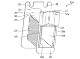
また、内周側鍔部26の径方向内側面には、角穴24aの周方向長さに亘って、壁20、21を延長するように径方向内側へと延出する一対の延出部38、38が形成されている。各延出部38の周方向中間部には、略半円形の切り欠き部38bが形成されている。各延出部38の周方向両端部の径方向内側には、それぞれ軸方向中間部側へと屈曲する鉤状爪部38aが形成されている。   Further, on the radially inner side surface of the inner circumferential flange 26, a pair of extending portions extending radially inward so as to extend the walls 20 and 21 over the circumferential length of the square hole 24a. 38, 38 are formed. A substantially semicircular cutout portion 38b is formed at the intermediate portion in the circumferential direction of each extension portion 38. A hook-like claw portion 38 a that is bent toward the axially intermediate portion side is formed on the radially inner side of both end portions in the circumferential direction of each extending portion 38.

コイル13は、インシュレータ12の胴部24の周囲に束線14が複数回に亘って巻回されて形成される。なお、本実施形態ではインシュレータ12への巻き方が異なる2種類のコイル13を有する。コイル13は、図5(a)及び(b)に示すように、インシュレータ12の胴部24に巻回されたコイル13の第1巻き端41が、胴部24の径方向外側寄りに位置し、第2巻き端42が胴部24の径方向内側から異相となるコイル13を跨いで径方向外側に延びる。第1のコイル13は、図5(a)に示すように、第1巻き端41が、図中左側の溝29に挿入され、その端部41aが外周側鍔部25から径方向外方に僅かに突出するようにその長さが設定される。また、第1のコイル13は、第2巻き端42が、径方向内向き傾斜面33に軸方向に並ぶようにして溝部35を斜め右下方に通過し内側巻線支持部31に係止される。この内側巻線支持部31から先は、図2に示すように径方向外側に延びてその端部42aが周方向に隣り合う同相のコイル13の第1巻き端41の端部41aに接合されるため、異相となるコイル13を跨ぐ渡り部14T分に加えて端部42aが外周側鍔部25から径方向外方に僅かに突出するようにその長さが設定される。   The coil 13 is formed by winding the bundle wire 14 a plurality of times around the trunk portion 24 of the insulator 12. In the present embodiment, there are two types of coils 13 that are differently wound around the insulator 12. As shown in FIGS. 5 (a) and 5 (b), the coil 13 has a first winding end 41 of the coil 13 wound around the body 24 of the insulator 12 positioned on the radially outer side of the body 24. The second winding end 42 extends radially outward from the radially inner side of the body portion 24 across the coil 13 that is in a different phase. As shown in FIG. 5 (a), the first coil 13 has a first winding end 41 inserted into the groove 29 on the left side in the drawing, and the end 41a is radially outward from the outer peripheral side flange 25. The length is set so as to protrude slightly. Further, the first coil 13 passes through the groove 35 obliquely downward to the right so that the second winding end 42 is axially aligned with the radially inwardly inclined surface 33 and is locked to the inner winding support 31. The As shown in FIG. 2, the tip of the inner winding support 31 extends outward in the radial direction, and its end 42a is joined to the end 41a of the first winding end 41 of the in-phase coil 13 adjacent in the circumferential direction. Therefore, the length is set so that the end portion 42a slightly protrudes radially outward from the outer peripheral side flange portion 25 in addition to the crossing portion 14T straddling the coil 13 which is a different phase.

また、図5(b)に示すように、第2のコイル13は、第1巻き端41が、図中右側の溝28に挿入され、その端部41aが外周側鍔部25から径方向外方に僅かに突出するようにその長さが設定される。また、第2のコイル13は、第2巻き端42が、内側巻線支持部32に巻き掛けられて径方向内向き傾斜面34に軸方向に並ぶようにして溝部36を斜め左下方に延びる。この内側巻線支持部32から先は、図2に示すように径方向外側に延びてその端部42aが周方向に隣り合う同相のコイル13の第1巻き端41の端部41aに接合されるため、異相となるコイル13を跨ぐ渡り部14T分に加えて端部42aが外周側鍔部25から径方向外方に僅かに突出するようにその長さが設定される。   Further, as shown in FIG. 5B, the second coil 13 has a first winding end 41 inserted into the groove 28 on the right side in the drawing, and its end 41a is radially outward from the outer peripheral side flange 25. The length is set so as to protrude slightly toward the end. Further, the second coil 13 extends the groove 36 obliquely to the lower left so that the second winding end 42 is wound around the inner winding support portion 32 and aligned in the axial direction with the radially inward inclined surface 34. . As shown in FIG. 2, the tip of the inner winding support 32 extends outward in the radial direction, and its end 42a is joined to the end 41a of the first winding end 41 of the coil 13 of the same phase adjacent in the circumferential direction. Therefore, the length is set so that the end portion 42a slightly protrudes radially outward from the outer peripheral side flange portion 25 in addition to the crossing portion 14T straddling the coil 13 which is a different phase.

図2に戻り、各相8個ずつのコイル13(U相、V相及びW相コイル13u、13v、13w)は、それぞれステータコア11の半周分に相当する4個ずつ、2つのコイル群18(18u、18v、18w)に分けられている。即ち、ステータ10に対して左方向回りに形成されるコイル群18(図2中、境界線Pの左側に位置するコイル群)のコイル13は、第1のコイル13から構成され、ステータ10に対して右回りに形成されるコイル群18(図2中、境界線Pの右側に位置するコイル群)のコイル13は、第2のコイル13から構成されている。   Returning to FIG. 2, the eight coils 13 (U-phase, V-phase and W-phase coils 13 u, 13 v, 13 w) for each phase are divided into two coil groups 18 (four corresponding to the half circumference of the stator core 11). 18u, 18v, 18w). That is, the coil 13 of the coil group 18 (a coil group located on the left side of the boundary line P in FIG. 2) formed in the counterclockwise direction with respect to the stator 10 is composed of the first coil 13. On the other hand, the coil 13 of the coil group 18 (coil group positioned on the right side of the boundary line P in FIG. 2) formed clockwise is composed of the second coil 13.

但し、図2に示す実施形態においては、ステータ10に対して右回りに形成されるコイル群18の第2のコイル13の内、後述する中性点に接続される3個のコイル13(13u、13v、13w)は、中性点との接続を容易にするため、第1巻き端41が、溝29に挿入されてその端部41aが上方に導出している。仮にこの3個のコイル13を第3のコイル13と称する。なお、ステータ10に対して右回りに形成されるコイル群18の全てのコイル13を、第2のコイル13で構成するようにしてもよい。この場合、中性点との接続が僅かに異なる。   However, in the embodiment shown in FIG. 2, among the second coils 13 of the coil group 18 formed clockwise with respect to the stator 10, three coils 13 (13 u) connected to a neutral point to be described later. 13v, 13w), the first winding end 41 is inserted into the groove 29 and its end 41a is led upward to facilitate connection with the neutral point. Temporarily, these three coils 13 are called the 3rd coil 13. FIG. Note that all the coils 13 of the coil group 18 formed clockwise with respect to the stator 10 may be constituted by the second coils 13. In this case, the connection with the neutral point is slightly different.

図2において、境界線Pの両側に最も近接して配置された同相の一対のコイル13から導出される束線14、具体的には、ステータ10に対して左回りに形成されるU相コイル群18uの第1のU相コイル13u、及びステータ10に対して右回りに形成されるU相コイル群18uの第2のU相コイル13uの、それぞれの第2巻き端42の端部42aが、U相接続端子15uに接続されている。   In FIG. 2, the bundled wire 14 derived from the pair of coils 13 having the same phase arranged closest to both sides of the boundary line P, specifically, the U-phase coil formed counterclockwise with respect to the stator 10. The end portions 42a of the second winding ends 42 of the first U-phase coil 13u of the group 18u and the second U-phase coil 13u of the U-phase coil group 18u formed clockwise with respect to the stator 10 are provided. , U-phase connection terminal 15u.

同様に、境界線Pの両側に最も近接して配置された一対のV相コイル13vの第2巻き端42の端部42aがV相接続端子15vに接続され、一対のW相コイル13wの第2巻き端42の端部42aがW相接続端子15wに接続されている。   Similarly, the end portions 42a of the second winding ends 42 of the pair of V-phase coils 13v arranged closest to both sides of the boundary line P are connected to the V-phase connection terminal 15v, and the first of the pair of W-phase coils 13w An end 42a of the second winding end 42 is connected to the W-phase connection terminal 15w.

また、左方向回りに形成されるコイル群18と右方向回りに形成されるコイル群18とが出会う位置、即ち、各相の接続端子15(U相、V相及びW相接続端子15u、15v、15w)の反対側で、境界線Pを挟んで両側に配置された各相一対、6個のコイル13の第1巻き端41の端部41aは、隣り合うコイル13の端部41a同士が、それぞれ接続線40によって接続されて、中性点を構成する。   Further, the position where the coil group 18 formed in the counterclockwise direction and the coil group 18 formed in the clockwise direction meet, that is, the connection terminals 15 of each phase (U-phase, V-phase and W-phase connection terminals 15u, 15v). , 15w), the ends 41a of the first winding ends 41 of each phase pair and the six coils 13 arranged on both sides with the boundary line P interposed therebetween are the ends 41a of the adjacent coils 13. These are connected by connection lines 40 to form a neutral point.

更に、左方向回りに形成されるコイル群18の各第1のコイル13の第2巻き端42は、隣り合うコイル13の溝部36に挿入されて係止され、その端部42aが、周方向に隣り合う同相コイルの外周側鍔部25の径方向外側に延びる第1巻き端41の端部41aに接合されている。   Furthermore, the 2nd winding end 42 of each 1st coil 13 of the coil group 18 formed in the left direction is inserted and latched in the groove part 36 of the adjacent coil 13, and the edge part 42a is circumferential direction. Are joined to the end portion 41a of the first winding end 41 that extends radially outward of the outer peripheral side flange portion 25 of the in-phase coil adjacent to each other.

また、右方向回りに形成されるコイル群18のコイル13も同様に、各第2のコイル13の第2巻き端42は、インシュレータ12の溝部36を通って隣り合うコイル13の溝部35に挿入されて係止され、その端部42aが、周方向に隣り合う同相コイルの外周側鍔部25の径方向外側に延びる第1巻き端41の端部41aに接合されている。図6も参照して、第1巻き端41の端部41aと第2巻き端42の端部42aの接合部14aは、絶縁材50によって覆われてインシュレータ12に固定されている。なお、接合処理は、超音波溶接装置により超音波を印加すること等により行われ、絶縁処理は、絶縁材50である粉末ワニスを固化させて接合部14aを覆い、インシュレータ12の外周側鍔部25に固定することで行われる。   Similarly, in the coil 13 of the coil group 18 formed in the clockwise direction, the second winding end 42 of each second coil 13 is inserted into the groove portion 35 of the adjacent coil 13 through the groove portion 36 of the insulator 12. Thus, the end 42a is joined to the end 41a of the first winding end 41 extending outward in the radial direction of the outer peripheral side flange 25 of the in-phase coil adjacent in the circumferential direction. Referring also to FIG. 6, the joint portion 14 a between the end portion 41 a of the first winding end 41 and the end portion 42 a of the second winding end 42 is covered with an insulating material 50 and fixed to the insulator 12. The joining process is performed by applying an ultrasonic wave with an ultrasonic welding apparatus, and the insulating process solidifies the powder varnish that is the insulating material 50 to cover the joining part 14a, and the outer peripheral side flange of the insulator 12 This is done by fixing to 25.

各コイル13をステータコア11に固定する際には、インシュレータ12に束線14を巻回して独立したコイル13を作成した後で、各ティース11bにコイル13を径方向外側から装着する。装着時、ティース11bをインシュレータ12の角穴24aに挿入する際には、各延出部38および各鉤状爪部38aが、ティース11bの軸方向面に沿うようにそれぞれ軸方向外向きに弾性変形する。鉤状爪部38aがステータコア11の内周壁11dに到達した時点で、延出部38および鉤状爪部38aが弾性変形から解放され、鉤状爪部38aがステータコア11の内周壁11dと係合する(図7参照。尚、図7においては、図の簡略化のために束線14等は省略されている)。各延出部38には切り欠き部38bが形成されているので、全て同形状のインシュレータ12を用いてもボルト穴17を塞ぐことなく、複数のコイル13をステータコア11に装着することができる(図2参照)。このように、インシュレータ12の鉤状爪部38aがステータコア11の内周壁11dと係合することにより、各コイル13が周方向両端部および軸方向両端部においてステータコア11に確実に固定される。   When each coil 13 is fixed to the stator core 11, the bundle wire 14 is wound around the insulator 12 to create an independent coil 13, and then the coil 13 is attached to each tooth 11b from the outside in the radial direction. When the teeth 11b are inserted into the square holes 24a of the insulator 12 at the time of mounting, the extending portions 38 and the hook-shaped claw portions 38a are elastically outward in the axial direction along the axial surface of the teeth 11b. Deform. When the hook-shaped claw portion 38a reaches the inner peripheral wall 11d of the stator core 11, the extending portion 38 and the hook-shaped claw portion 38a are released from elastic deformation, and the hook-shaped claw portion 38a engages with the inner peripheral wall 11d of the stator core 11. (Refer to FIG. 7. In FIG. 7, the bundled wires 14 and the like are omitted for simplification of the drawing). Since the notches 38b are formed in each extending portion 38, a plurality of coils 13 can be mounted on the stator core 11 without blocking the bolt holes 17 even if the insulators 12 having the same shape are used. (See FIG. 2). As described above, the hook-like claw portion 38a of the insulator 12 is engaged with the inner peripheral wall 11d of the stator core 11, so that each coil 13 is securely fixed to the stator core 11 at both circumferential end portions and axial end portions.

上記したように、本実施形態の電動機1によれば、各インシュレータ12には、ステータコア10の径方向内側に延出する延出部38が形成され、延出部38が、ステータコア12と係合する鉤状爪部38aを有するので、インシュレータ12がステータ11のティース11bから抜け出すことを防止して、インシュレータ12とロータ6との接触を確実に防止することができる。   As described above, according to the electric motor 1 of the present embodiment, each insulator 12 is formed with the extending portion 38 that extends radially inward of the stator core 10, and the extending portion 38 is engaged with the stator core 12. Therefore, the insulator 12 can be prevented from slipping out of the teeth 11b of the stator 11 and the contact between the insulator 12 and the rotor 6 can be reliably prevented.

また、延出部38がステータコア12の軸方向面に沿って延出し、ステータコア12が円環状の内周壁12dを有し、鉤状爪部38aが、ステータコア12の内周壁12dと係合するので、簡易な構造によりインシュレータ12をステータコア11に固定することができる。   Further, the extension portion 38 extends along the axial surface of the stator core 12, the stator core 12 has an annular inner peripheral wall 12 d, and the hook-shaped claw portion 38 a engages with the inner peripheral wall 12 d of the stator core 12. The insulator 12 can be fixed to the stator core 11 with a simple structure.

また、鉤状爪部38aが延出部38の周方向両端部に形成され、延出部38の周方向両端部の間に切り欠き部38bが形成されるので、ステータ10をモータハウジング2に固定するためのボルト17のための空間が残るので、全て同形状のインシュレータ12を用いることができ、製造が容易になる。   Further, the hook-shaped claw portions 38 a are formed at both ends in the circumferential direction of the extending portion 38, and the notches 38 b are formed between the both ends in the circumferential direction of the extending portion 38, so that the stator 10 is attached to the motor housing 2. Since the space for the bolts 17 for fixing remains, the insulator 12 having the same shape can be used, and the manufacture becomes easy.

尚、インシュレータに形成される延在部および鉤状爪部は、前述した実施形態の形状に限定されない。例えば、図8に示すインシュレータ12´のように、切り欠き部38bが設けられず、延出部38´の周方向長さに亘って鉤状爪部38a´が形成されてもよい。   In addition, the extension part and hook-shaped nail | claw part formed in an insulator are not limited to the shape of embodiment mentioned above. For example, like the insulator 12 ′ shown in FIG. 8, the notch 38 b may not be provided, and the hook-shaped claw 38 a ′ may be formed over the circumferential length of the extension 38 ′.

(第2実施形態)
次に、本発明の第2実施形態に係る外転型の電動機について、図9〜12を参照して説明する。なお、第2実施形態の電動機は、インシュレータとステータコアの構造およびこれらの係合方法において、第1実施形態の電動機と異なる。このため、第1実施形態と同一又は同等部分には同一符号又は相当符号を付して説明を簡略化又は省略する。
(Second Embodiment)
Next, an abduction motor according to a second embodiment of the present invention will be described with reference to FIGS. The electric motor of the second embodiment is different from the electric motor of the first embodiment in the structure of the insulator and the stator core and the engagement method thereof. For this reason, the same or equivalent parts as those in the first embodiment are denoted by the same or corresponding symbols, and description thereof is simplified or omitted.

図9に示すように、第2実施形態に係る電動機のステータ10Aは、円環部11aから径方向外側に向かって放射状に突出形成された複数(24個)のティース11bを有するステータコア11Aと、それぞれのティース11bの周囲にインシュレータ12Aを介して形成された複数のコイル13と、を備える。   As shown in FIG. 9, the stator 10A of the electric motor according to the second embodiment includes a stator core 11A having a plurality (24) of teeth 11b that are radially projected from the annular portion 11a toward the radially outer side, And a plurality of coils 13 formed around the teeth 11b via insulators 12A.

図10に示すように、ステータコア11Aの円環部11aの外周面には、複数の凹部11eが形成されている。これらの凹部11eは、円環部11aと各ティース11bとの境界部分に沿って、軸方向長さに亘って平行に形成されている。凹部11eは、円環部11aの外周面から、ティース11bの径方向内側に回り込むような形状に形成される。   As shown in FIG. 10, a plurality of recesses 11e are formed on the outer peripheral surface of the annular portion 11a of the stator core 11A. These concave portions 11e are formed in parallel over the axial length along the boundary portion between the annular portion 11a and each tooth 11b. The recessed part 11e is formed in the shape which wraps around to the radial inside of the teeth 11b from the outer peripheral surface of the annular part 11a.

図11に示すように、インシュレータ12Aの内周側鍔部26の径方向内側面には、角穴24aの軸方向長さに亘って、壁22、23を延長するように径方向内側へと延出する一対の延出部39、39が形成されている。各延出部39には、角穴24a側へ突出する鉤状爪部39aが形成されている。これらの延出部39をステータコア11Aに形成された凹部11eにそれぞれ挿入し、各鉤状爪部39aをティース11bの径方向内側で凹部11eに係合させることにより、各コイル13(インシュレータ12A)がステータコア10Aに固定される(図12参照)。このように、インシュレータ12Aの鉤状爪部39aがステータコア11Aの凹部11eと係合することにより、各コイル13が周方向両端部において軸方向長さに亘りステータコア11Aに確実に固定される。   As shown in FIG. 11, on the radially inner side surface of the inner circumferential flange 26 of the insulator 12A, the walls 22 and 23 are extended radially inward over the axial length of the square hole 24a. A pair of extending portions 39, 39 extending is formed. Each extending portion 39 is formed with a hook-shaped claw portion 39a that protrudes toward the square hole 24a. These extending portions 39 are respectively inserted into the recesses 11e formed in the stator core 11A, and the respective hook-shaped claw portions 39a are engaged with the recesses 11e on the radially inner side of the teeth 11b, whereby each coil 13 (insulator 12A). Is fixed to the stator core 10A (see FIG. 12). As described above, the hook-shaped claw portion 39a of the insulator 12A engages with the concave portion 11e of the stator core 11A, whereby each coil 13 is reliably fixed to the stator core 11A over the axial length at both circumferential ends.

上記したように、本実施形態の電動機によれば、延出部39がティース11bの周方向面に沿って延出し、鉤状爪部39aが、ステータコア11Aの隣り合うティース11b間に形成された凹部11dと係合するので、簡易な構造によりインシュレータ12をステータコア11に固定することができる。また、全て同形状のインシュレータ12を用いることができ、製造が容易になる。   As described above, according to the electric motor of the present embodiment, the extending portion 39 extends along the circumferential surface of the tooth 11b, and the hook-shaped claw portion 39a is formed between the adjacent teeth 11b of the stator core 11A. Since it engages with the recess 11d, the insulator 12 can be fixed to the stator core 11 with a simple structure. Further, the insulator 12 having the same shape can be used, and the manufacture becomes easy.

尚、本発明は、前述した実施形態に限定されるものではなく、適宜、変形、改良等が可能である。   In addition, this invention is not limited to embodiment mentioned above, A deformation | transformation, improvement, etc. are possible suitably.

1 電動機
10、10A ステータ
11、11A ステータコア
11a 円環部
11b ティース
11d 内周壁
11e 凹部
12、12´、12A インシュレータ
13 コイル
38、38´ 延出部
38a、38a´ 鉤状爪部
38b 切り欠き部
39 延出部
39a 鉤状爪部
DESCRIPTION OF SYMBOLS 1 Electric motor 10, 10A Stator 11, 11A Stator core 11a Ring part 11b Teeth 11d Inner peripheral wall 11e Recess 12, 12 ', 12A Insulator 13 Coil 38, 38' Extension part 38a, 38a 'Hook-shaped claw part 38b Notch part 39 Extension part 39a Sponge claw part

Claims (4)

周方向に所定の間隔で配置され放射状に突出する複数のティースを有するステータコアと、各ティースに配置される複数のインシュレータと、前記インシュレータの外周に巻線を巻回することで形成される複数のコイルと、を有するステータと、
前記ステータの径方向外側に配置される円環状のロータと、を備える外転型の電動機であって、
各インシュレータには、前記ステータコアの径方向内側に延出する延出部が形成され、
前記延出部が、前記ステータコアと係合する鉤状爪部を有することを特徴とする外転型の電動機。
A stator core having a plurality of teeth arranged at predetermined intervals in the circumferential direction and projecting radially, a plurality of insulators arranged on each tooth, and a plurality of windings wound around the outer circumference of the insulator A stator having a coil;
An abduction-type electric motor provided with an annular rotor disposed on a radially outer side of the stator,
Each insulator is formed with an extending portion extending radially inward of the stator core,
An abduction motor, wherein the extending portion has a hook-like claw portion that engages with the stator core.
前記ステータコアが円環状の内周壁を有し、
前記延出部が前記ステータコアの軸方向面に沿って延出し、
前記鉤状爪部が、前記ステータコアの前記内周壁と係合することを特徴とする請求項1に記載の外転型の電動機。
The stator core has an annular inner peripheral wall;
The extending portion extends along the axial surface of the stator core;
The abduction-type electric motor according to claim 1, wherein the hook-shaped claw portion engages with the inner peripheral wall of the stator core.
前記鉤状爪部が前記延出部の周方向両端部に形成され、
前記延出部の周方向両端部の間に切り欠き部が形成されることを特徴とする請求項2に記載の外転型の電動機。
The hook-shaped claw portions are formed at both ends in the circumferential direction of the extending portion,
The abduction motor according to claim 2, wherein a notch is formed between both ends in the circumferential direction of the extension.
前記延出部が前記ティースの周方向面に沿って延出し、
前記鉤状爪部が、前記ステータコアの隣り合うティース間に形成された凹部と係合することを特徴とする請求項1に記載の外転型の電動機。
The extending portion extends along a circumferential surface of the teeth;
The abduction-type electric motor according to claim 1, wherein the hook-shaped claw portion engages with a concave portion formed between adjacent teeth of the stator core.
JP2010248946A 2010-11-05 2010-11-05 Outer rotor type electric motor Pending JP2012105372A (en)

Priority Applications (1)

Application Number Priority Date Filing Date Title
JP2010248946A JP2012105372A (en) 2010-11-05 2010-11-05 Outer rotor type electric motor

Applications Claiming Priority (1)

Application Number Priority Date Filing Date Title
JP2010248946A JP2012105372A (en) 2010-11-05 2010-11-05 Outer rotor type electric motor

Publications (1)

Publication Number Publication Date
JP2012105372A true JP2012105372A (en) 2012-05-31

Family

ID=46395116

Family Applications (1)

Application Number Title Priority Date Filing Date
JP2010248946A Pending JP2012105372A (en) 2010-11-05 2010-11-05 Outer rotor type electric motor

Country Status (1)

Country Link
JP (1) JP2012105372A (en)

Cited By (5)

* Cited by examiner, † Cited by third party
Publication number Priority date Publication date Assignee Title
JP2012139749A (en) * 2010-12-28 2012-07-26 Hitachi Koki Co Ltd Power tool
JP2014230305A (en) * 2013-05-17 2014-12-08 株式会社安川電機 Bobbin and rotary electric machine
JP6112525B1 (en) * 2016-06-23 2017-04-12 公益財団法人岡山県産業振興財団 Bobbin structure
JP2019068605A (en) * 2017-09-29 2019-04-25 日本電産サーボ株式会社 Stator and motor
US20190252930A1 (en) * 2018-02-09 2019-08-15 Miba Sinter Austria Gmbh Stator arrangement for an axial-flow machine

Cited By (7)

* Cited by examiner, † Cited by third party
Publication number Priority date Publication date Assignee Title
JP2012139749A (en) * 2010-12-28 2012-07-26 Hitachi Koki Co Ltd Power tool
JP2014230305A (en) * 2013-05-17 2014-12-08 株式会社安川電機 Bobbin and rotary electric machine
JP6112525B1 (en) * 2016-06-23 2017-04-12 公益財団法人岡山県産業振興財団 Bobbin structure
JP2017229178A (en) * 2016-06-23 2017-12-28 公益財団法人岡山県産業振興財団 Bobbin structure
JP2019068605A (en) * 2017-09-29 2019-04-25 日本電産サーボ株式会社 Stator and motor
US20190252930A1 (en) * 2018-02-09 2019-08-15 Miba Sinter Austria Gmbh Stator arrangement for an axial-flow machine
US10886796B2 (en) * 2018-02-09 2021-01-05 Miba Sinter Austria Gmbh Stator arrangement for an axial-flow machine

Similar Documents

Publication Publication Date Title
JP5004110B2 (en) Outer rotor type salient pole concentrated winding motor
JP5306411B2 (en) Rotating electric machine
US7545063B2 (en) Wire-connection structure of motor
US10439453B2 (en) Stator
JP6058164B2 (en) Rotating electric machine
JP5318072B2 (en) Motor salient pole concentrated winding stator
JP2015042047A (en) Stator of dynamo-electric machine
JP6358086B2 (en) Stator assembly apparatus and stator assembly method
WO2019073724A1 (en) Stator for dynamo-electric machine
JP2012105372A (en) Outer rotor type electric motor
US10840656B2 (en) Bus bar unit and rotary electric machine having the same
WO2011155327A1 (en) Salient pole concentrated winding stator for electric motor and manufacturing method for same
JP6760227B2 (en) Rotating machine stator
US20190393740A1 (en) Stator and rotary electric machine
JP5481351B2 (en) Abduction type electric motor
WO2021230058A1 (en) Motor
JP2016059130A (en) Stator of dynamo-electric machine
CN108336847B (en) Slot insulation paper and stator of rotating electric machine
JP5306309B2 (en) Abduction type electric motor
JP5481302B2 (en) Abduction type electric motor
JP2017225208A (en) Armature, rotary electric machine, and manufacturing method of armature
JP2013115974A (en) Stator of rotary electric machine
KR20180013692A (en) Stator and motor having the same
JP2012034498A (en) Outer rotor type salient pole concentrated winding motor
WO2021205653A1 (en) Electric motor stator and electric motor