JP6187516B2 - Hybrid vehicle - Google Patents
Hybrid vehicle Download PDFInfo
- Publication number
- JP6187516B2 JP6187516B2 JP2015059339A JP2015059339A JP6187516B2 JP 6187516 B2 JP6187516 B2 JP 6187516B2 JP 2015059339 A JP2015059339 A JP 2015059339A JP 2015059339 A JP2015059339 A JP 2015059339A JP 6187516 B2 JP6187516 B2 JP 6187516B2
- Authority
- JP
- Japan
- Prior art keywords
- converter
- alternator
- battery
- power
- voltage
- Prior art date
- Legal status (The legal status is an assumption and is not a legal conclusion. Google has not performed a legal analysis and makes no representation as to the accuracy of the status listed.)
- Active
Links
Images


Classifications
-
- B—PERFORMING OPERATIONS; TRANSPORTING
- B60—VEHICLES IN GENERAL
- B60W—CONJOINT CONTROL OF VEHICLE SUB-UNITS OF DIFFERENT TYPE OR DIFFERENT FUNCTION; CONTROL SYSTEMS SPECIALLY ADAPTED FOR HYBRID VEHICLES; ROAD VEHICLE DRIVE CONTROL SYSTEMS FOR PURPOSES NOT RELATED TO THE CONTROL OF A PARTICULAR SUB-UNIT
- B60W20/00—Control systems specially adapted for hybrid vehicles
- B60W20/10—Controlling the power contribution of each of the prime movers to meet required power demand
- B60W20/13—Controlling the power contribution of each of the prime movers to meet required power demand in order to stay within battery power input or output limits; in order to prevent overcharging or battery depletion
-
- B—PERFORMING OPERATIONS; TRANSPORTING
- B60—VEHICLES IN GENERAL
- B60L—PROPULSION OF ELECTRICALLY-PROPELLED VEHICLES; SUPPLYING ELECTRIC POWER FOR AUXILIARY EQUIPMENT OF ELECTRICALLY-PROPELLED VEHICLES; ELECTRODYNAMIC BRAKE SYSTEMS FOR VEHICLES IN GENERAL; MAGNETIC SUSPENSION OR LEVITATION FOR VEHICLES; MONITORING OPERATING VARIABLES OF ELECTRICALLY-PROPELLED VEHICLES; ELECTRIC SAFETY DEVICES FOR ELECTRICALLY-PROPELLED VEHICLES
- B60L50/00—Electric propulsion with power supplied within the vehicle
- B60L50/10—Electric propulsion with power supplied within the vehicle using propulsion power supplied by engine-driven generators, e.g. generators driven by combustion engines
- B60L50/16—Electric propulsion with power supplied within the vehicle using propulsion power supplied by engine-driven generators, e.g. generators driven by combustion engines with provision for separate direct mechanical propulsion
-
- B—PERFORMING OPERATIONS; TRANSPORTING
- B60—VEHICLES IN GENERAL
- B60K—ARRANGEMENT OR MOUNTING OF PROPULSION UNITS OR OF TRANSMISSIONS IN VEHICLES; ARRANGEMENT OR MOUNTING OF PLURAL DIVERSE PRIME-MOVERS IN VEHICLES; AUXILIARY DRIVES FOR VEHICLES; INSTRUMENTATION OR DASHBOARDS FOR VEHICLES; ARRANGEMENTS IN CONNECTION WITH COOLING, AIR INTAKE, GAS EXHAUST OR FUEL SUPPLY OF PROPULSION UNITS IN VEHICLES
- B60K6/00—Arrangement or mounting of plural diverse prime-movers for mutual or common propulsion, e.g. hybrid propulsion systems comprising electric motors and internal combustion engines ; Control systems therefor, i.e. systems controlling two or more prime movers, or controlling one of these prime movers and any of the transmission, drive or drive units Informative references: mechanical gearings with secondary electric drive F16H3/72; arrangements for handling mechanical energy structurally associated with the dynamo-electric machine H02K7/00; machines comprising structurally interrelated motor and generator parts H02K51/00; dynamo-electric machines not otherwise provided for in H02K see H02K99/00
- B60K6/20—Arrangement or mounting of plural diverse prime-movers for mutual or common propulsion, e.g. hybrid propulsion systems comprising electric motors and internal combustion engines ; Control systems therefor, i.e. systems controlling two or more prime movers, or controlling one of these prime movers and any of the transmission, drive or drive units Informative references: mechanical gearings with secondary electric drive F16H3/72; arrangements for handling mechanical energy structurally associated with the dynamo-electric machine H02K7/00; machines comprising structurally interrelated motor and generator parts H02K51/00; dynamo-electric machines not otherwise provided for in H02K see H02K99/00 the prime-movers consisting of electric motors and internal combustion engines, e.g. HEVs
- B60K6/22—Arrangement or mounting of plural diverse prime-movers for mutual or common propulsion, e.g. hybrid propulsion systems comprising electric motors and internal combustion engines ; Control systems therefor, i.e. systems controlling two or more prime movers, or controlling one of these prime movers and any of the transmission, drive or drive units Informative references: mechanical gearings with secondary electric drive F16H3/72; arrangements for handling mechanical energy structurally associated with the dynamo-electric machine H02K7/00; machines comprising structurally interrelated motor and generator parts H02K51/00; dynamo-electric machines not otherwise provided for in H02K see H02K99/00 the prime-movers consisting of electric motors and internal combustion engines, e.g. HEVs characterised by apparatus, components or means specially adapted for HEVs
- B60K6/28—Arrangement or mounting of plural diverse prime-movers for mutual or common propulsion, e.g. hybrid propulsion systems comprising electric motors and internal combustion engines ; Control systems therefor, i.e. systems controlling two or more prime movers, or controlling one of these prime movers and any of the transmission, drive or drive units Informative references: mechanical gearings with secondary electric drive F16H3/72; arrangements for handling mechanical energy structurally associated with the dynamo-electric machine H02K7/00; machines comprising structurally interrelated motor and generator parts H02K51/00; dynamo-electric machines not otherwise provided for in H02K see H02K99/00 the prime-movers consisting of electric motors and internal combustion engines, e.g. HEVs characterised by apparatus, components or means specially adapted for HEVs characterised by the electric energy storing means, e.g. batteries or capacitors
-
- B—PERFORMING OPERATIONS; TRANSPORTING
- B60—VEHICLES IN GENERAL
- B60K—ARRANGEMENT OR MOUNTING OF PROPULSION UNITS OR OF TRANSMISSIONS IN VEHICLES; ARRANGEMENT OR MOUNTING OF PLURAL DIVERSE PRIME-MOVERS IN VEHICLES; AUXILIARY DRIVES FOR VEHICLES; INSTRUMENTATION OR DASHBOARDS FOR VEHICLES; ARRANGEMENTS IN CONNECTION WITH COOLING, AIR INTAKE, GAS EXHAUST OR FUEL SUPPLY OF PROPULSION UNITS IN VEHICLES
- B60K6/00—Arrangement or mounting of plural diverse prime-movers for mutual or common propulsion, e.g. hybrid propulsion systems comprising electric motors and internal combustion engines ; Control systems therefor, i.e. systems controlling two or more prime movers, or controlling one of these prime movers and any of the transmission, drive or drive units Informative references: mechanical gearings with secondary electric drive F16H3/72; arrangements for handling mechanical energy structurally associated with the dynamo-electric machine H02K7/00; machines comprising structurally interrelated motor and generator parts H02K51/00; dynamo-electric machines not otherwise provided for in H02K see H02K99/00
- B60K6/20—Arrangement or mounting of plural diverse prime-movers for mutual or common propulsion, e.g. hybrid propulsion systems comprising electric motors and internal combustion engines ; Control systems therefor, i.e. systems controlling two or more prime movers, or controlling one of these prime movers and any of the transmission, drive or drive units Informative references: mechanical gearings with secondary electric drive F16H3/72; arrangements for handling mechanical energy structurally associated with the dynamo-electric machine H02K7/00; machines comprising structurally interrelated motor and generator parts H02K51/00; dynamo-electric machines not otherwise provided for in H02K see H02K99/00 the prime-movers consisting of electric motors and internal combustion engines, e.g. HEVs
- B60K6/22—Arrangement or mounting of plural diverse prime-movers for mutual or common propulsion, e.g. hybrid propulsion systems comprising electric motors and internal combustion engines ; Control systems therefor, i.e. systems controlling two or more prime movers, or controlling one of these prime movers and any of the transmission, drive or drive units Informative references: mechanical gearings with secondary electric drive F16H3/72; arrangements for handling mechanical energy structurally associated with the dynamo-electric machine H02K7/00; machines comprising structurally interrelated motor and generator parts H02K51/00; dynamo-electric machines not otherwise provided for in H02K see H02K99/00 the prime-movers consisting of electric motors and internal combustion engines, e.g. HEVs characterised by apparatus, components or means specially adapted for HEVs
- B60K6/38—Arrangement or mounting of plural diverse prime-movers for mutual or common propulsion, e.g. hybrid propulsion systems comprising electric motors and internal combustion engines ; Control systems therefor, i.e. systems controlling two or more prime movers, or controlling one of these prime movers and any of the transmission, drive or drive units Informative references: mechanical gearings with secondary electric drive F16H3/72; arrangements for handling mechanical energy structurally associated with the dynamo-electric machine H02K7/00; machines comprising structurally interrelated motor and generator parts H02K51/00; dynamo-electric machines not otherwise provided for in H02K see H02K99/00 the prime-movers consisting of electric motors and internal combustion engines, e.g. HEVs characterised by apparatus, components or means specially adapted for HEVs characterised by the driveline clutches
- B60K6/387—Actuated clutches, i.e. clutches engaged or disengaged by electric, hydraulic or mechanical actuating means
-
- B—PERFORMING OPERATIONS; TRANSPORTING
- B60—VEHICLES IN GENERAL
- B60K—ARRANGEMENT OR MOUNTING OF PROPULSION UNITS OR OF TRANSMISSIONS IN VEHICLES; ARRANGEMENT OR MOUNTING OF PLURAL DIVERSE PRIME-MOVERS IN VEHICLES; AUXILIARY DRIVES FOR VEHICLES; INSTRUMENTATION OR DASHBOARDS FOR VEHICLES; ARRANGEMENTS IN CONNECTION WITH COOLING, AIR INTAKE, GAS EXHAUST OR FUEL SUPPLY OF PROPULSION UNITS IN VEHICLES
- B60K6/00—Arrangement or mounting of plural diverse prime-movers for mutual or common propulsion, e.g. hybrid propulsion systems comprising electric motors and internal combustion engines ; Control systems therefor, i.e. systems controlling two or more prime movers, or controlling one of these prime movers and any of the transmission, drive or drive units Informative references: mechanical gearings with secondary electric drive F16H3/72; arrangements for handling mechanical energy structurally associated with the dynamo-electric machine H02K7/00; machines comprising structurally interrelated motor and generator parts H02K51/00; dynamo-electric machines not otherwise provided for in H02K see H02K99/00
- B60K6/20—Arrangement or mounting of plural diverse prime-movers for mutual or common propulsion, e.g. hybrid propulsion systems comprising electric motors and internal combustion engines ; Control systems therefor, i.e. systems controlling two or more prime movers, or controlling one of these prime movers and any of the transmission, drive or drive units Informative references: mechanical gearings with secondary electric drive F16H3/72; arrangements for handling mechanical energy structurally associated with the dynamo-electric machine H02K7/00; machines comprising structurally interrelated motor and generator parts H02K51/00; dynamo-electric machines not otherwise provided for in H02K see H02K99/00 the prime-movers consisting of electric motors and internal combustion engines, e.g. HEVs
- B60K6/42—Arrangement or mounting of plural diverse prime-movers for mutual or common propulsion, e.g. hybrid propulsion systems comprising electric motors and internal combustion engines ; Control systems therefor, i.e. systems controlling two or more prime movers, or controlling one of these prime movers and any of the transmission, drive or drive units Informative references: mechanical gearings with secondary electric drive F16H3/72; arrangements for handling mechanical energy structurally associated with the dynamo-electric machine H02K7/00; machines comprising structurally interrelated motor and generator parts H02K51/00; dynamo-electric machines not otherwise provided for in H02K see H02K99/00 the prime-movers consisting of electric motors and internal combustion engines, e.g. HEVs characterised by the architecture of the hybrid electric vehicle
- B60K6/48—Parallel type
-
- B—PERFORMING OPERATIONS; TRANSPORTING
- B60—VEHICLES IN GENERAL
- B60K—ARRANGEMENT OR MOUNTING OF PROPULSION UNITS OR OF TRANSMISSIONS IN VEHICLES; ARRANGEMENT OR MOUNTING OF PLURAL DIVERSE PRIME-MOVERS IN VEHICLES; AUXILIARY DRIVES FOR VEHICLES; INSTRUMENTATION OR DASHBOARDS FOR VEHICLES; ARRANGEMENTS IN CONNECTION WITH COOLING, AIR INTAKE, GAS EXHAUST OR FUEL SUPPLY OF PROPULSION UNITS IN VEHICLES
- B60K6/00—Arrangement or mounting of plural diverse prime-movers for mutual or common propulsion, e.g. hybrid propulsion systems comprising electric motors and internal combustion engines ; Control systems therefor, i.e. systems controlling two or more prime movers, or controlling one of these prime movers and any of the transmission, drive or drive units Informative references: mechanical gearings with secondary electric drive F16H3/72; arrangements for handling mechanical energy structurally associated with the dynamo-electric machine H02K7/00; machines comprising structurally interrelated motor and generator parts H02K51/00; dynamo-electric machines not otherwise provided for in H02K see H02K99/00
- B60K6/20—Arrangement or mounting of plural diverse prime-movers for mutual or common propulsion, e.g. hybrid propulsion systems comprising electric motors and internal combustion engines ; Control systems therefor, i.e. systems controlling two or more prime movers, or controlling one of these prime movers and any of the transmission, drive or drive units Informative references: mechanical gearings with secondary electric drive F16H3/72; arrangements for handling mechanical energy structurally associated with the dynamo-electric machine H02K7/00; machines comprising structurally interrelated motor and generator parts H02K51/00; dynamo-electric machines not otherwise provided for in H02K see H02K99/00 the prime-movers consisting of electric motors and internal combustion engines, e.g. HEVs
- B60K6/50—Architecture of the driveline characterised by arrangement or kind of transmission units
- B60K6/54—Transmission for changing ratio
- B60K6/547—Transmission for changing ratio the transmission being a stepped gearing
-
- B—PERFORMING OPERATIONS; TRANSPORTING
- B60—VEHICLES IN GENERAL
- B60L—PROPULSION OF ELECTRICALLY-PROPELLED VEHICLES; SUPPLYING ELECTRIC POWER FOR AUXILIARY EQUIPMENT OF ELECTRICALLY-PROPELLED VEHICLES; ELECTRODYNAMIC BRAKE SYSTEMS FOR VEHICLES IN GENERAL; MAGNETIC SUSPENSION OR LEVITATION FOR VEHICLES; MONITORING OPERATING VARIABLES OF ELECTRICALLY-PROPELLED VEHICLES; ELECTRIC SAFETY DEVICES FOR ELECTRICALLY-PROPELLED VEHICLES
- B60L50/00—Electric propulsion with power supplied within the vehicle
- B60L50/10—Electric propulsion with power supplied within the vehicle using propulsion power supplied by engine-driven generators, e.g. generators driven by combustion engines
- B60L50/13—Electric propulsion with power supplied within the vehicle using propulsion power supplied by engine-driven generators, e.g. generators driven by combustion engines using AC generators and AC motors
-
- B—PERFORMING OPERATIONS; TRANSPORTING
- B60—VEHICLES IN GENERAL
- B60W—CONJOINT CONTROL OF VEHICLE SUB-UNITS OF DIFFERENT TYPE OR DIFFERENT FUNCTION; CONTROL SYSTEMS SPECIALLY ADAPTED FOR HYBRID VEHICLES; ROAD VEHICLE DRIVE CONTROL SYSTEMS FOR PURPOSES NOT RELATED TO THE CONTROL OF A PARTICULAR SUB-UNIT
- B60W10/00—Conjoint control of vehicle sub-units of different type or different function
- B60W10/04—Conjoint control of vehicle sub-units of different type or different function including control of propulsion units
- B60W10/06—Conjoint control of vehicle sub-units of different type or different function including control of propulsion units including control of combustion engines
-
- B—PERFORMING OPERATIONS; TRANSPORTING
- B60—VEHICLES IN GENERAL
- B60W—CONJOINT CONTROL OF VEHICLE SUB-UNITS OF DIFFERENT TYPE OR DIFFERENT FUNCTION; CONTROL SYSTEMS SPECIALLY ADAPTED FOR HYBRID VEHICLES; ROAD VEHICLE DRIVE CONTROL SYSTEMS FOR PURPOSES NOT RELATED TO THE CONTROL OF A PARTICULAR SUB-UNIT
- B60W10/00—Conjoint control of vehicle sub-units of different type or different function
- B60W10/04—Conjoint control of vehicle sub-units of different type or different function including control of propulsion units
- B60W10/08—Conjoint control of vehicle sub-units of different type or different function including control of propulsion units including control of electric propulsion units, e.g. motors or generators
-
- B—PERFORMING OPERATIONS; TRANSPORTING
- B60—VEHICLES IN GENERAL
- B60K—ARRANGEMENT OR MOUNTING OF PROPULSION UNITS OR OF TRANSMISSIONS IN VEHICLES; ARRANGEMENT OR MOUNTING OF PLURAL DIVERSE PRIME-MOVERS IN VEHICLES; AUXILIARY DRIVES FOR VEHICLES; INSTRUMENTATION OR DASHBOARDS FOR VEHICLES; ARRANGEMENTS IN CONNECTION WITH COOLING, AIR INTAKE, GAS EXHAUST OR FUEL SUPPLY OF PROPULSION UNITS IN VEHICLES
- B60K6/00—Arrangement or mounting of plural diverse prime-movers for mutual or common propulsion, e.g. hybrid propulsion systems comprising electric motors and internal combustion engines ; Control systems therefor, i.e. systems controlling two or more prime movers, or controlling one of these prime movers and any of the transmission, drive or drive units Informative references: mechanical gearings with secondary electric drive F16H3/72; arrangements for handling mechanical energy structurally associated with the dynamo-electric machine H02K7/00; machines comprising structurally interrelated motor and generator parts H02K51/00; dynamo-electric machines not otherwise provided for in H02K see H02K99/00
- B60K6/20—Arrangement or mounting of plural diverse prime-movers for mutual or common propulsion, e.g. hybrid propulsion systems comprising electric motors and internal combustion engines ; Control systems therefor, i.e. systems controlling two or more prime movers, or controlling one of these prime movers and any of the transmission, drive or drive units Informative references: mechanical gearings with secondary electric drive F16H3/72; arrangements for handling mechanical energy structurally associated with the dynamo-electric machine H02K7/00; machines comprising structurally interrelated motor and generator parts H02K51/00; dynamo-electric machines not otherwise provided for in H02K see H02K99/00 the prime-movers consisting of electric motors and internal combustion engines, e.g. HEVs
- B60K6/42—Arrangement or mounting of plural diverse prime-movers for mutual or common propulsion, e.g. hybrid propulsion systems comprising electric motors and internal combustion engines ; Control systems therefor, i.e. systems controlling two or more prime movers, or controlling one of these prime movers and any of the transmission, drive or drive units Informative references: mechanical gearings with secondary electric drive F16H3/72; arrangements for handling mechanical energy structurally associated with the dynamo-electric machine H02K7/00; machines comprising structurally interrelated motor and generator parts H02K51/00; dynamo-electric machines not otherwise provided for in H02K see H02K99/00 the prime-movers consisting of electric motors and internal combustion engines, e.g. HEVs characterised by the architecture of the hybrid electric vehicle
- B60K6/48—Parallel type
- B60K2006/4808—Electric machine connected or connectable to gearbox output shaft
-
- B—PERFORMING OPERATIONS; TRANSPORTING
- B60—VEHICLES IN GENERAL
- B60K—ARRANGEMENT OR MOUNTING OF PROPULSION UNITS OR OF TRANSMISSIONS IN VEHICLES; ARRANGEMENT OR MOUNTING OF PLURAL DIVERSE PRIME-MOVERS IN VEHICLES; AUXILIARY DRIVES FOR VEHICLES; INSTRUMENTATION OR DASHBOARDS FOR VEHICLES; ARRANGEMENTS IN CONNECTION WITH COOLING, AIR INTAKE, GAS EXHAUST OR FUEL SUPPLY OF PROPULSION UNITS IN VEHICLES
- B60K6/00—Arrangement or mounting of plural diverse prime-movers for mutual or common propulsion, e.g. hybrid propulsion systems comprising electric motors and internal combustion engines ; Control systems therefor, i.e. systems controlling two or more prime movers, or controlling one of these prime movers and any of the transmission, drive or drive units Informative references: mechanical gearings with secondary electric drive F16H3/72; arrangements for handling mechanical energy structurally associated with the dynamo-electric machine H02K7/00; machines comprising structurally interrelated motor and generator parts H02K51/00; dynamo-electric machines not otherwise provided for in H02K see H02K99/00
- B60K6/20—Arrangement or mounting of plural diverse prime-movers for mutual or common propulsion, e.g. hybrid propulsion systems comprising electric motors and internal combustion engines ; Control systems therefor, i.e. systems controlling two or more prime movers, or controlling one of these prime movers and any of the transmission, drive or drive units Informative references: mechanical gearings with secondary electric drive F16H3/72; arrangements for handling mechanical energy structurally associated with the dynamo-electric machine H02K7/00; machines comprising structurally interrelated motor and generator parts H02K51/00; dynamo-electric machines not otherwise provided for in H02K see H02K99/00 the prime-movers consisting of electric motors and internal combustion engines, e.g. HEVs
- B60K6/42—Arrangement or mounting of plural diverse prime-movers for mutual or common propulsion, e.g. hybrid propulsion systems comprising electric motors and internal combustion engines ; Control systems therefor, i.e. systems controlling two or more prime movers, or controlling one of these prime movers and any of the transmission, drive or drive units Informative references: mechanical gearings with secondary electric drive F16H3/72; arrangements for handling mechanical energy structurally associated with the dynamo-electric machine H02K7/00; machines comprising structurally interrelated motor and generator parts H02K51/00; dynamo-electric machines not otherwise provided for in H02K see H02K99/00 the prime-movers consisting of electric motors and internal combustion engines, e.g. HEVs characterised by the architecture of the hybrid electric vehicle
- B60K6/48—Parallel type
- B60K2006/4825—Electric machine connected or connectable to gearbox input shaft
-
- B—PERFORMING OPERATIONS; TRANSPORTING
- B60—VEHICLES IN GENERAL
- B60L—PROPULSION OF ELECTRICALLY-PROPELLED VEHICLES; SUPPLYING ELECTRIC POWER FOR AUXILIARY EQUIPMENT OF ELECTRICALLY-PROPELLED VEHICLES; ELECTRODYNAMIC BRAKE SYSTEMS FOR VEHICLES IN GENERAL; MAGNETIC SUSPENSION OR LEVITATION FOR VEHICLES; MONITORING OPERATING VARIABLES OF ELECTRICALLY-PROPELLED VEHICLES; ELECTRIC SAFETY DEVICES FOR ELECTRICALLY-PROPELLED VEHICLES
- B60L2210/00—Converter types
- B60L2210/10—DC to DC converters
-
- B—PERFORMING OPERATIONS; TRANSPORTING
- B60—VEHICLES IN GENERAL
- B60W—CONJOINT CONTROL OF VEHICLE SUB-UNITS OF DIFFERENT TYPE OR DIFFERENT FUNCTION; CONTROL SYSTEMS SPECIALLY ADAPTED FOR HYBRID VEHICLES; ROAD VEHICLE DRIVE CONTROL SYSTEMS FOR PURPOSES NOT RELATED TO THE CONTROL OF A PARTICULAR SUB-UNIT
- B60W2510/00—Input parameters relating to a particular sub-units
- B60W2510/24—Energy storage means
- B60W2510/242—Energy storage means for electrical energy
- B60W2510/244—Charge state
-
- B—PERFORMING OPERATIONS; TRANSPORTING
- B60—VEHICLES IN GENERAL
- B60W—CONJOINT CONTROL OF VEHICLE SUB-UNITS OF DIFFERENT TYPE OR DIFFERENT FUNCTION; CONTROL SYSTEMS SPECIALLY ADAPTED FOR HYBRID VEHICLES; ROAD VEHICLE DRIVE CONTROL SYSTEMS FOR PURPOSES NOT RELATED TO THE CONTROL OF A PARTICULAR SUB-UNIT
- B60W2710/00—Output or target parameters relating to a particular sub-units
- B60W2710/24—Energy storage means
- B60W2710/242—Energy storage means for electrical energy
- B60W2710/248—Current for loading or unloading
-
- B—PERFORMING OPERATIONS; TRANSPORTING
- B60—VEHICLES IN GENERAL
- B60W—CONJOINT CONTROL OF VEHICLE SUB-UNITS OF DIFFERENT TYPE OR DIFFERENT FUNCTION; CONTROL SYSTEMS SPECIALLY ADAPTED FOR HYBRID VEHICLES; ROAD VEHICLE DRIVE CONTROL SYSTEMS FOR PURPOSES NOT RELATED TO THE CONTROL OF A PARTICULAR SUB-UNIT
- B60W2710/00—Output or target parameters relating to a particular sub-units
- B60W2710/30—Auxiliary equipments
- B60W2710/305—Auxiliary equipments target power to auxiliaries
-
- B—PERFORMING OPERATIONS; TRANSPORTING
- B60—VEHICLES IN GENERAL
- B60Y—INDEXING SCHEME RELATING TO ASPECTS CROSS-CUTTING VEHICLE TECHNOLOGY
- B60Y2200/00—Type of vehicle
- B60Y2200/90—Vehicles comprising electric prime movers
- B60Y2200/92—Hybrid vehicles
-
- B—PERFORMING OPERATIONS; TRANSPORTING
- B60—VEHICLES IN GENERAL
- B60Y—INDEXING SCHEME RELATING TO ASPECTS CROSS-CUTTING VEHICLE TECHNOLOGY
- B60Y2300/00—Purposes or special features of road vehicle drive control systems
- B60Y2300/60—Control of electric machines, e.g. problems related to electric motors or generators
-
- B—PERFORMING OPERATIONS; TRANSPORTING
- B60—VEHICLES IN GENERAL
- B60Y—INDEXING SCHEME RELATING TO ASPECTS CROSS-CUTTING VEHICLE TECHNOLOGY
- B60Y2300/00—Purposes or special features of road vehicle drive control systems
- B60Y2300/91—Battery charging
-
- B—PERFORMING OPERATIONS; TRANSPORTING
- B60—VEHICLES IN GENERAL
- B60Y—INDEXING SCHEME RELATING TO ASPECTS CROSS-CUTTING VEHICLE TECHNOLOGY
- B60Y2400/00—Special features of vehicle units
- B60Y2400/20—Energy converters
-
- B—PERFORMING OPERATIONS; TRANSPORTING
- B60—VEHICLES IN GENERAL
- B60Y—INDEXING SCHEME RELATING TO ASPECTS CROSS-CUTTING VEHICLE TECHNOLOGY
- B60Y2400/00—Special features of vehicle units
- B60Y2400/60—Electric Machines, e.g. motors or generators
- B60Y2400/602—DC Machines
-
- Y—GENERAL TAGGING OF NEW TECHNOLOGICAL DEVELOPMENTS; GENERAL TAGGING OF CROSS-SECTIONAL TECHNOLOGIES SPANNING OVER SEVERAL SECTIONS OF THE IPC; TECHNICAL SUBJECTS COVERED BY FORMER USPC CROSS-REFERENCE ART COLLECTIONS [XRACs] AND DIGESTS
- Y02—TECHNOLOGIES OR APPLICATIONS FOR MITIGATION OR ADAPTATION AGAINST CLIMATE CHANGE
- Y02T—CLIMATE CHANGE MITIGATION TECHNOLOGIES RELATED TO TRANSPORTATION
- Y02T10/00—Road transport of goods or passengers
- Y02T10/60—Other road transportation technologies with climate change mitigation effect
- Y02T10/62—Hybrid vehicles
-
- Y—GENERAL TAGGING OF NEW TECHNOLOGICAL DEVELOPMENTS; GENERAL TAGGING OF CROSS-SECTIONAL TECHNOLOGIES SPANNING OVER SEVERAL SECTIONS OF THE IPC; TECHNICAL SUBJECTS COVERED BY FORMER USPC CROSS-REFERENCE ART COLLECTIONS [XRACs] AND DIGESTS
- Y10—TECHNICAL SUBJECTS COVERED BY FORMER USPC
- Y10S—TECHNICAL SUBJECTS COVERED BY FORMER USPC CROSS-REFERENCE ART COLLECTIONS [XRACs] AND DIGESTS
- Y10S903/00—Hybrid electric vehicles, HEVS
- Y10S903/902—Prime movers comprising electrical and internal combustion motors
- Y10S903/903—Prime movers comprising electrical and internal combustion motors having energy storing means, e.g. battery, capacitor
- Y10S903/93—Conjoint control of different elements
Description
本発明は、ハイブリッド車両に関し、詳しくは、走行用の動力を出力可能なエンジンと、走行用の動力を出力可能なモータと、モータが接続された第1電力ラインに接続された第1バッテリと、車載電気機器と、車載電気機器が接続された第2電力ラインに接続された第2バッテリと、第1電力ラインの電力を変圧して第2電力ラインに供給するDC/DCコンバータと、エンジンにより駆動され発電した電力を第2電力ラインに供給するオルタネータと、を備えるハイブリッド車両に関する。 The present invention relates to a hybrid vehicle, and more specifically, an engine capable of outputting driving power, a motor capable of outputting driving power, and a first battery connected to a first power line to which the motor is connected. An on-vehicle electrical device, a second battery connected to a second power line to which the on-vehicle electrical device is connected, a DC / DC converter that transforms the power of the first power line and supplies it to the second power line, and an engine The present invention relates to a hybrid vehicle comprising: an alternator that supplies electric power driven and generated by a second power line.
従来、この種のハイブリッド車両としては、エンジンと、モータと、高圧バッテリと、車載電装品と、低圧バッテリと、DC/DCコンバータと、オルタネータと、を備えるものが提案されている(例えば、特許文献1参照)。エンジンおよびモータは、走行用の動力を出力する。高圧バッテリは、モータに電力を供給する。低圧バッテリは、車載電装品に電力を供給する。DC/DCコンバータは、高圧バッテリからの電力を降圧して低圧バッテリや車載電装品に供給する。オルタネータは、エンジンにより駆動されている。オルタネータは、発電した電力を低圧バッテリや車載電装品に供給する。この装置では、車載電装品の電力消費量がさほど大きくないときには、DC/DCコンバータから供給される電力が低圧バッテリや車載電装品に供給される。そして、車載電装品の電力消費量が大きいときには、DC/DCコンバータから出力可能電力を供給し、この電力に加えてオルタネータからの発電電力も車載電装品や低圧バッテリに供給する。これにより、車載電装品の電力消費量が大きいときでも、充分な電力を車載電装品と低圧バッテリとに供給することができ、低圧バッテリを充分に充電することができるとしている。 Conventionally, as this type of hybrid vehicle, a vehicle including an engine, a motor, a high voltage battery, an on-vehicle electrical component, a low voltage battery, a DC / DC converter, and an alternator has been proposed (for example, a patent). Reference 1). The engine and motor output driving power. The high voltage battery supplies power to the motor. The low voltage battery supplies power to the on-vehicle electrical components. The DC / DC converter steps down the power from the high voltage battery and supplies it to the low voltage battery and the on-vehicle electrical components. The alternator is driven by an engine. The alternator supplies the generated power to a low-voltage battery or an on-vehicle electrical component. In this apparatus, when the power consumption of the in-vehicle electrical component is not so large, the power supplied from the DC / DC converter is supplied to the low voltage battery and the in-vehicle electrical component. When the power consumption of the in-vehicle electrical component is large, outputable power is supplied from the DC / DC converter, and in addition to this power, the generated power from the alternator is also supplied to the in-vehicle electrical component and the low-voltage battery. Thereby, even when the power consumption of the in-vehicle electrical component is large, sufficient power can be supplied to the in-vehicle electrical component and the low-voltage battery, and the low-voltage battery can be sufficiently charged.
しかしながら、上述のハイブリッド車両では、エネルギ効率が低下する場合がある。一般に、オルタネータは、出力電流が低いときの効率が悪い。そのため、車載電装品の電力消費量のうちDC/DCコンバータからの電力では補えない分の電力をオルタネータから供給すると、オルタネータを低い出力電流で駆動する機会が多くなり、エネルギ効率が低下してしまう。 However, in the above-described hybrid vehicle, energy efficiency may be reduced. In general, an alternator is inefficient when the output current is low. For this reason, if the alternator supplies power that cannot be compensated for by the power from the DC / DC converter in the power consumption of the on-vehicle electrical components, there are many opportunities to drive the alternator with a low output current, resulting in reduced energy efficiency. .
本発明のハイブリッド車両は、低圧バッテリを充電する際のエネルギ効率の向上を図ることを主目的とする。 The main purpose of the hybrid vehicle of the present invention is to improve energy efficiency when charging a low-voltage battery.
本発明のハイブリッド車両は、上述の主目的を達成するために以下の手段を採った。 The hybrid vehicle of the present invention employs the following means in order to achieve the main object described above.
本発明のハイブリッド車両は、
走行用の動力を出力可能なエンジンと、
走行用の動力を出力可能なモータと、
前記モータが接続された第1電力ラインに接続された第1バッテリと、
車載電気機器と、
前記車載電気機器が接続された第2電力ラインに接続された第2バッテリと、
前記第1電力ラインの電力を変圧して前記第2電力ラインに供給するDC/DCコンバータと、
前記エンジンにより駆動され発電した電力を前記第2電力ラインに供給するオルタネータと、
前記第2バッテリの蓄電割合または前記第2バッテリの端子間電圧が所定閾値未満となったときには、前記オルタネータを停止して前記DC/DCコンバータから前記第2電力ラインに電力が供給されるよう前記DC/DCコンバータと前記オルタネータとを制御する第1制御を実行し、前記第1制御を実行している最中に前記第2バッテリの蓄電割合または前記第2バッテリの端子間電圧が所定閾値から低下したときには、前記DC/DCコンバータからの電力と前記オルタネータからの電力とが前記第2電力ラインに供給されるよう前記DC/DCコンバータと前記オルタネータとを制御する第2制御を実行する制御手段と、
を備えるハイブリッド車両であって、
前記第2制御では、効率良く駆動する所定駆動点で前記オルタネータを駆動させながら、前記DC/DCコンバータからの電力と前記オルタネータからの電力とが前記第2電力ラインに供給されるよう前記DC/DCコンバータと前記オルタネータとを制御する、
ことを特徴とする。
The hybrid vehicle of the present invention
An engine capable of outputting power for traveling;
A motor capable of outputting driving power;
A first battery connected to a first power line to which the motor is connected;
In-vehicle electrical equipment,
A second battery connected to a second power line to which the in-vehicle electric device is connected;
A DC / DC converter that transforms the power of the first power line and supplies it to the second power line;
An alternator for supplying the second power line with electric power driven by the engine;
When the storage ratio of the second battery or the voltage between the terminals of the second battery becomes less than a predetermined threshold, the alternator is stopped and power is supplied from the DC / DC converter to the second power line. The first control for controlling the DC / DC converter and the alternator is executed, and during the execution of the first control, the storage ratio of the second battery or the voltage between the terminals of the second battery is reduced from a predetermined threshold value. Control means for executing a second control for controlling the DC / DC converter and the alternator so that the electric power from the DC / DC converter and the electric power from the alternator are supplied to the second electric power line when the voltage drops. When,
A hybrid vehicle comprising:
In the second control, the DC / DC converter and the alternator are supplied with electric power from the DC / DC converter and electric power from the alternator while driving the alternator at a predetermined driving point for efficient driving. Controlling a DC converter and the alternator;
It is characterized by that.
この本発明のハイブリッド車両では、前記第2バッテリの蓄電割合または前記第2バッテリの端子間電圧が所定閾値未満となったときには、オルタネータを停止してDC/DCコンバータから第2電力ラインに電力が供給されるようDC/DCコンバータとオルタネータとを制御する第1制御を実行し、第1制御を実行している最中に第2バッテリの蓄電割合または前記第2バッテリの端子間電圧が所定閾値から低下したときには、DC/DCコンバータからの電力とオルタネータからの電力とが第2電力ラインに供給されるようDC/DCコンバータとオルタネータとを制御する第2制御を実行する。これにより、車載電気機器での消費電力を賄いつつ低圧バッテリを充電することができる。そして、第2制御では、効率良く駆動する所定駆動点でオルタネータを駆動させながら、DC/DCコンバータからの電力とオルタネータからの電力とが第2電力ラインに供給されるようDC/DCコンバータとオルタネータとを制御する。これにより、車載電気機器での消費電力を賄いつつ低圧バッテリを充電することができる。このとき、オルタネータを効率良く駆動させるから、エネルギ効率の向上を図ることができる。ここで、「蓄電割合」とは、第2バッテリが蓄電可能な全容量に対する実際に蓄電されている容量の割合のことである。また、「所定閾値」は、低圧バッテリの充電を開始する閾値である。 In the hybrid vehicle of the present invention, when the storage ratio of the second battery or the voltage between the terminals of the second battery becomes less than a predetermined threshold value, the alternator is stopped and power is supplied from the DC / DC converter to the second power line. The first control for controlling the DC / DC converter and the alternator so as to be supplied is executed, and while the first control is being executed, the storage ratio of the second battery or the voltage between the terminals of the second battery is a predetermined threshold value. When the voltage decreases from the above, the second control is executed to control the DC / DC converter and the alternator so that the power from the DC / DC converter and the power from the alternator are supplied to the second power line. Thereby, the low voltage battery can be charged while covering the power consumption in the in-vehicle electric device. In the second control, the DC / DC converter and the alternator are supplied such that the electric power from the DC / DC converter and the electric power from the alternator are supplied to the second electric power line while driving the alternator at a predetermined driving point for efficient driving. And control. Thereby, the low voltage battery can be charged while covering the power consumption in the in-vehicle electric device. At this time, since the alternator is driven efficiently, energy efficiency can be improved. Here, the “power storage ratio” is the ratio of the capacity that is actually stored with respect to the total capacity that the second battery can store. The “predetermined threshold value” is a threshold value for starting charging of the low-voltage battery.
こうした本発明のハイブリッド車両において、前記所定駆動点は、所定出力電圧と前記オルタネータが効率良く駆動する電流範囲内の所定出力電流とからなり、前記第2制御では、前記DC/DCコンバータについては、前記第2バッテリの端子間電圧が所定電圧となるよう制御する、ものとしてもよい。オルタネータを効率良く駆動しながらオルタネータから所定電流と所定電圧とで定める電力を第2電力ラインに供給することにより、エネルギ効率の向上を図ることができる。ここで、「所定出力電圧」は、第2バッテリの定格電圧とすることもできる。また、「所定出力電流」は、DC/DCコンバータが供給可能な最大電流である、ものとすることもできる。 In such a hybrid vehicle of the present invention, the predetermined driving point includes a predetermined output voltage and a predetermined output current within a current range that the alternator efficiently drives. In the second control, the DC / DC converter Control may be performed so that the voltage between the terminals of the second battery becomes a predetermined voltage. Energy efficiency can be improved by supplying power determined by a predetermined current and a predetermined voltage from the alternator to the second power line while driving the alternator efficiently. Here, the “predetermined output voltage” may be the rated voltage of the second battery. Further, the “predetermined output current” may be the maximum current that can be supplied by the DC / DC converter.
次に、本発明を実施するための形態を実施例を用いて説明する。 Next, the form for implementing this invention is demonstrated using an Example.
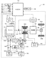
図1は、本発明の一実施例としてのバッテリ充電装置が搭載されたハイブリッド自動車20の構成の概略を示す構成図である。実施例のハイブリッド自動車20は、図示するように、エンジン22と、モータMGと、インバータ41と、変速機46と、高圧バッテリ50と、低圧バッテリ60と、オルタネータ62と、車載電気機器類66と、DC/DCコンバータ68と、ハイブリッド用電子制御ユニット(以下、HVECUという)70と、を備える。
FIG. 1 is a configuration diagram showing an outline of the configuration of a
エンジン22は、ガソリンや軽油などを燃料として動力を出力する内燃機関として構成されている。エンジン22は、エアクリーナによって清浄された空気をスロットルバルブを介して吸入すると共に燃料噴射弁から燃料を噴射して、空気とガソリンとを混合する。そして、この混合気を吸気バルブを介して燃焼室に吸入する。そして、エンジン22は、吸入した混合気を点火プラグによる電気火花によって爆発燃焼させて、そのエネルギによって押し下げられるピストンの往復運動をクランクシャフト26の回転運動に変換する。このエンジン22は、エンジン用電子制御ユニット(以下、エンジンECUという)24により運転制御されている。
The
エンジンECU24は、図示しないが、CPUを中心とするマイクロプロセッサとして構成されており、CPUの他に、処理プログラムを記憶するROMやデータを一時的に記憶するRAM,入出力ポート,通信ポートを備える。エンジンECU24には、エンジン22を運転制御するのに必要な各種センサからの信号が入力ポートから入力されている。各種センサからの信号としては、以下のものを挙げることができる。エンジン22のクランクシャフト26の回転位置を検出するクランクポジションセンサからのクランク角θcr。スロットルバルブのポジションを検出するスロットルバルブポジションセンサからのスロットル開度TH。エンジンECU24からは、エンジン22を運転制御するための種々の制御信号が出力ポートを介して出力されている。種々の制御信号としては、以下のものを挙げることができる。燃料噴射弁への駆動信号。スロットルバルブのポジションを調節するスロットルモータへの駆動信号。イグナイタと一体化されたイグニッションコイルへの制御信号。エンジンECU24は、HVECU70と通信ポートを介して接続されている。このエンジンECU24は、HVECU70からの制御信号によりエンジン22を運転制御する。また、エンジンECU24は、必要に応じてエンジン22の運転状態に関するデータをHVECU70に出力する。エンジンECU24は、クランクポジションセンサにより検出されたクランク角θcrに基づいて、クランクシャフト26の回転数、即ち、エンジン22の回転数Neを演算している。
Although not shown, the
モータMGは、例えば同期発電電動機として構成されている。このモータMGは、回転子がクラッチK0を介してエンジン22のクランクシャフト26に接続されている。インバータ41は、高電圧系電力ライン54に接続されている。モータMGは、モータ用電子制御ユニット(以下、モータECUという)40によって、インバータ41の図示しないスイッチング素子がスイッチング制御されることにより、回転駆動される。
The motor MG is configured as a synchronous generator motor, for example. The motor MG has a rotor connected to the
モータECU40は、図示しないが、CPUを中心とするマイクロプロセッサとして構成されており、CPUの他に、処理プログラムを記憶するROMやデータを一時的に記憶するRAM,入出力ポート,通信ポートを備える。モータECU40には、モータMGを駆動制御するのに必要な各種センサからの信号が入力ポートを介して入力されている。各種センサからの信号としては、以下のものを挙げることができる。モータMGの回転子の回転位置を検出する回転位置検出センサ43からの回転位置θm1。モータMGの各相に流れる電流を検出する電流センサからの相電流。モータECU40からは、インバータ41の図示しないスイッチング素子へのスイッチング制御信号などが出力ポートを介して出力されている。モータECU40は、HVECU70と通信ポートを介して接続されている。このモータECU40は、HVECU70からの制御信号によってモータMGを駆動制御する。また、モータECU40は、必要に応じてモータMGの駆動状態に関するデータをHVECU70に出力する。モータECU40は、回転位置検出センサ43により検出されたモータMGの回転子の回転位置θmに基づいてモータMGの回転数Nmを演算している。
Although not shown, the
変速機46は、トルクコンバータと多段変速機構とを有する自動変速機として構成されている。変速機46は、モータMGの回転子に接続されると共に駆動軸36とデファレンシャルギヤ37とを介して駆動輪38a,38bに接続されている。変速機46は、オートマチックトランスミッション用電子制御ユニット(以下、ATECUという)48により制御されている。
The
ATECU48は、図示しないが、CPUを中心とするマイクロプロセッサとして構成されており、CPUの他に、処理プログラムを記憶するROMやデータを一時的に記憶するRAM,入出力ポート,通信ポートを備える。ATECU48には、変速機46を制御するのに必要な信号が入力されている。ATECU48からは、変速機46への各種制御信号などが出力ポートを介して出力されている。各種制御信号としては、以下のものを挙げることができる。トルクコンバータのロックアップクラッチへの制御信号。多段変速機への変速制御信号。クラッチK0への制御信号。ATECU48は、HVECU70と通信ポートを介して接続されている。このATECU48は、HVECU70からの変速制御信号によって変速機46を変速制御する。また、ATECU48は、必要に応じて変速機46の状態に関するデータをHVECU70に出力する。
Although not shown, the
高圧バッテリ50は、例えばリチウムイオン二次電池やニッケル水素二次電池として構成されている。高圧バッテリ50は、システムメインリレー(SMR)51を介して高電圧系電力ライン54に接続されており、モータMGとインバータ41を介して電力をやりとりする。高圧バッテリ50は、バッテリ用電子制御ユニット(以下、バッテリECUという)52により管理されている。
The
低圧バッテリ60は、例えば、高圧バッテリ50より定格電圧が低い鉛蓄電池として構成されている。低圧バッテリ60は、車載電気機器類66,オルタネータ62,DC/DCコンバータ68と共に低電圧系電力ライン64に接続されている。低圧バッテリ60は、バッテリECU52により管理されている。
The
車載電気機器類66は、空調装置やオーディオシステムなどの複数の電気機器を含んでいる。車載電気機器類66は、上述したように、低電圧系電力ライン64に接続されている。
The in-vehicle
バッテリECU52は、図示しないが、CPUを中心とするマイクロプロセッサとして構成されており、CPUの他に、処理プログラムを記憶するROMやデータを一時的に記憶するRAM,入出力ポート,通信ポートを備える。バッテリECU52には、高圧バッテリ50,低圧バッテリ60を管理するのに必要な各種センサからの信号が入力ポートを介して入力されている。各種センサからの信号としては、以下のものを挙げることができる。高圧バッテリ50の端子間に設置された電圧センサからの端子間電圧Vbh。低圧バッテリ60の端子間に設置された電圧センサ60aからの端子間電圧Vbl。バッテリECU52は、HVECU70と通信ポートを介して接続されている。このバッテリECU52は、必要に応じて高圧バッテリ50の状態に関するデータをHVECU70に出力する。
Although not shown, the
オルタネータ62は、エンジン22のクランクシャフト26にベルト61を介して接続されている。オルタネータ62は、エンジン22の動力により発電を行ない、発電した電力を低電圧系電力ライン64に供給している。オルタネータ62は、HVECU70により制御されている。
The
DC/DCコンバータ68は、高電圧系電力ライン54と低電圧系電力ライン64とに接続されている。DC/DCコンバータ68は、インバータ41を介したモータMGからの電力や高圧バッテリ50からの電力を降圧して低電圧系電力ライン64に供給している。DC/DCコンバータ68は、HVECU70により制御されている。
The DC /
HVECU70は、図示しないが、CPUを中心とするマイクロプロセッサとして構成されており、CPUの他に、処理プログラムを記憶するROMやデータを一時的に記憶するRAM,入出力ポート,通信ポートを備える。HVECU70には、各種センサからの信号が入力ポートを介して入力されている。各種センサからの信号としては、以下のものを挙げることができる。イグニッションスイッチ80からのイグニッション信号。シフトレバー81の操作位置を検出するシフトポジションセンサ82からのシフトポジションSP。アクセルペダル83の踏み込み量を検出するアクセルペダルポジションセンサ84からのアクセル開度Acc。ブレーキペダル85の踏み込み量を検出するブレーキペダルポジションセンサ86からのブレーキペダルポジションBP。車速センサ88からの車速V。オルタネータ62の出力電流を検出する電流センサ62aからの出力電流Ialt。HVECU70は、上述したように、エンジンECU24やモータECU40,ATECU48,バッテリECU52と通信ポートを介して接続されている。このHVECU70は、エンジンECU24やモータECU40,ATECU48,バッテリECU52と各種制御信号やデータのやりとりを行なっている。
Although not shown, the
こうして構成された実施例のハイブリッド自動車20は、クラッチK0をオフ(非接続)としてエンジン22の運転を停止した状態でモータMGからの動力を変速機46により変速して走行したり、クラッチK0をオン(接続)としてエンジン22からの動力とモータMGからの動力とで走行したりする。
The thus configured
次に、こうして構成された実施例のハイブリッド自動車20の動作、特に、低圧バッテリ60の端子間電圧が低下したときの動作について説明する。図2は、HVECU70により実行される端子間電圧低下時制御ルーチンの一例を示すフローチャートである。本ルーチンは、クラッチK0をオフ(非接続)としてエンジン22の運転を停止した状態でモータMGからの動力で走行しており、且つ、オルタネータ62とDC/DCコンバータ68とを駆動停止しているときに実行される。
Next, the operation of the
本ルーチンが実行されると、HVECU70は、低圧バッテリ60の端子間電圧Vblを入力する処理を実行する(ステップS100)。端子間電圧Vblは、電圧センサ60aにより検出されたものをバッテリECU52から通信により入力するものとした。
When this routine is executed, the
続いて、入力した端子間電圧Vblと判定用閾値VAとを比較する(ステップS110)。ここで、判定用閾値VAは、低圧バッテリ60の充電を開始するか否かを判定するための閾値であり、低圧バッテリ60の定格電圧より若干低い電圧であるものとした。
Subsequently, the input terminal voltage Vbl is compared with the determination threshold value VA (step S110). Here, the determination threshold value VA is a threshold value for determining whether or not charging of the
端子間電圧Vblが判定用閾値VA以上であるときには(ステップS110)、低圧バッテリ60の充電を開始する必要がないと判断して、DC/DCコンバータ68の駆動停止を継続して(ステップS200)、本ルーチンを終了する。
When the inter-terminal voltage Vbl is equal to or higher than the determination threshold value VA (step S110), it is determined that there is no need to start charging the
端子間電圧Vblが判定用閾値VA未満であるときには(ステップS110)、低圧バッテリ60を充電する必要があると判断して、DC/DCコンバータ68の駆動を開始して、DC/DCコンバータ68の最大供給能力Pmaxの範囲内で低電圧バッテリ60の端子間電圧Vblが定格電圧となるようDC/DCコンバータ68を制御する(ステップS120)。ここで、オルタネータ62を駆動せずにDC/DCコンバータ68を駆動する理由について説明する。
When the inter-terminal voltage Vbl is less than the determination threshold value VA (step S110), it is determined that the
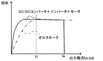
図3は、DC/DCコンバータ68の出力電流Idc(DC/DCコンバータ68が低電圧系電力ライン64に供給する電流)とDC/DCコンバータ68およびインバータ41,モータMGからなる電力供給系における効率との関係、および、オルタネータ62の出力電流Ialt(オルタネータ62が低電圧系電力ライン64に供給する電流)と効率との関係を示す説明図である。図中、実線は、出力電流IdcとDC/DCコンバータ68およびインバータ41,モータMGからなる電力供給系における効率との関係を示している。一点鎖線は、出力電流Ialtと効率とを示している。図示するように、出力電流が電流I1より低い低電流領域では、オルタネータ62から電流を出力するよりもDC/DCコンバータ68から電流を出力したほうが効率が良い。したがって、エネルギ効率の向上を図るため、低圧バッテリ60を充電する必要があると判断されたときには、オルタネータ62を駆動せずにまずはDC/DCコンバータ68を駆動するのである。
FIG. 3 shows the output current Idc (current supplied from the DC /
こうしてDC/DCコンバータ68を駆動したら、続いて、ステップS100と同様の処理で、低圧バッテリ60の端子間電圧Vblを入力し(ステップS130)、端子間電圧Vblと判定用閾値VBとを比較する(ステップS140)。ここで、判定用閾値VBは、低圧バッテリ60の充電を継続するか否かを判定するための閾値であり、実施例では、判定用閾値VAと同一の値または判定用閾値VAより若干高い値であるものとした。
After the DC /
端子間電圧Vblが判定用閾値VB以上であるときには(ステップS140)、低圧バッテリ60の充電をこれ以上継続する必要がないと判断して、DC/DCコンバータ68の駆動を停止して(ステップS200)、本ルーチンを終了する。
When the inter-terminal voltage Vbl is equal to or higher than the determination threshold value VB (step S140), it is determined that it is not necessary to continue charging the
端子間電圧Vblが判定用閾値VB未満であるときには(ステップS140)、車載電気機器類66での消費電力が大きいため低圧バッテリ60を充電できないと判断して、さらに、端子間電圧Vblと判定用閾値VCとを比較する(ステップS150)。ここで、判定用閾値VCは、DC/DCコンバータ68の駆動のみで低圧バッテリ60の端子間電圧Vblを回復できる場合があるか否かを判定するための閾値であり、判定用閾値VBより小さい値とした。
When the inter-terminal voltage Vbl is less than the determination threshold value VB (step S140), it is determined that the
端子間電圧Vblが判定用閾値VC以上であるときには(ステップS150)、DC/DCコンバータ68の駆動のみで低圧バッテリ60の端子間電圧Vblを回復できる場合があると判断して、ステップS120の処理に戻り、ステップS120〜S150の処理を繰り返し、DC/DCコンバータ68の駆動を継続する。そして、ステップS140の処理で端子間電圧Vblが判定用電圧VB以上となったときには、DC/DCコンバータ68の駆動を停止して(ステップS200)、本ルーチンを終了する。
When the inter-terminal voltage Vbl is equal to or higher than the determination threshold VC (step S150), it is determined that the inter-terminal voltage Vbl of the
端子間電圧Vblが判定用閾値VC未満であるときには(ステップS150)、車載電気機器類66の消費電力が大きいため、DC/DCコンバータ68のみの駆動では低圧バッテリ60の端子間電圧Vblを回復できないと判断して、エンジン始動指令をエンジンECU24に送信して、オルタネータ62からの電力とDC/DCコンバータ68からの電力とが低電圧系電力ライン64に供給されるようオルタネータ62とDC/DCコンバータ68とを制御する(ステップS160)。エンジン始動指令を受信したエンジンECU24は、スタータモータ27を用いてエンジン22を始動して運転を開始する制御を実行する。ここで、オルタネータ62については、所定電圧Vaと所定電流Iaとからなる所定駆動点で駆動するよう制御する。DC/DCコンバータ68については、低圧バッテリ60の端子間電圧Vblが定格電圧となるようとなるようDC/DCコンバータ68を制御する。ここで、所定電圧Vaは、低圧バッテリ60の定格電圧より若干高い電圧とした。また、所定電流Iaは、図3に示すように、オルタネータ62が効率良く駆動する範囲の電流I1以上の電流として予め定めた電流値(例えば、DC/DCコンバータ68の最大供給可能電流Imax)とした。これにより、オルタネータ62を効率良く駆動しながらオルタネータ62から所定電流Iaと所定電圧Vaとで定める電力を低電圧系電力ライン64に供給しながら、車載電気機器類66の消費電力を賄いつつ低電圧バッテリ60を充電するのに不足する分の電力をDC/DCコンバータ68から供給することができる。これにより、低電圧バッテリ60を充電することができる。ここで、オルタネータ62を所定駆動点で駆動させる理由について説明する。
When the inter-terminal voltage Vbl is less than the determination threshold VC (step S150), the power consumption of the in-vehicle
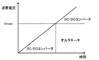
図4は、実施例において車載電気機器類66の消費電流とDC/DCコンバータ68の駆動領域とオルタネータ62の駆動領域とを説明するための説明図である。図5は、比較例において車載電気機器類66の消費電流が上昇したときのDC/DCコンバータ68の駆動領域とオルタネータ62の駆動領域とを説明するための説明図である。比較例では、低圧バッテリ60の端子間電圧Vblが判定用閾値VC未満になったときには、DC/DCコンバータ68から最大供給電流Imaxの電流が出力されるようDC/DCコンバータ68を制御し、DC/DCコンバータ68からの電力では車載電気機器類66の消費電力を補いつつ低圧バッテリ60を充電するのに不足する分の電力をオルタネータ62から供給するようオルタネータ62を制御するものとした。
FIG. 4 is an explanatory diagram for explaining the current consumption of the in-vehicle
実施例および比較例では、図4,5に示すように、車載電気機器類66の消費電流がDC/DCコンバータ68の最大供給電流Imaxに至るまでは、DC/DCコンバータ68からの供給電力で車載電気機器類66の消費電力を賄いつつ低圧バッテリ60を充電する。
In the embodiment and the comparative example, as shown in FIGS. 4 and 5, the supply power from the DC /
車載電気機器類66の消費電流が最大供給電流Imax以上となると、DC/DCコンバータ68のみでは車載電気機器類66の消費電流を賄うことができず、不足分は低圧バッテリ60から供給される。そのため、低圧バッテリ60の端子間電圧Vblが低下する。実施例および比較例では、こうした不足分の電流を補いつつ低圧バッテリ60を充電するために、図4,図5に示すように、オルタネータ62とDC/DCコンバータ68とを駆動する。このとき、比較例では、図5に示すように、DC/DCコンバータ68を最大供給電流Imaxで駆動し、DC/DCコンバータ68からの供給電流では不足する分の電流をオルタネータ62から供給する。そのため、オルタネータ62を低電流で駆動する機会が多くなる。実施例では、オルタネータ62については、出力電流Ialtを所定電流Iaとしてオルタネータ62を効率良く駆動させ、不足分の電流(電力)をDC/DCコンバータ68から供給する。そのため、DC/DCコンバータ68を低電流で駆動する機会が多くなる。図3に示したように、低電流領域では、オルタネータ62を駆動するよりDC/DCコンバータ68を駆動したほうが効率が良いから、比較例より、全体のエネルギ効率の向上を図ることができる。このように、オルタネータ62を所定駆動点で駆動させることにより、エネルギ効率の向上を図ることができる。
When the consumption current of the in-vehicle
こうしてオルタネータ62とDC/DCコンバータ68とを駆動したら、ステップS100の処理と同様に、端子間電圧Vblを入力し(ステップS170),入力した端子間電圧Vblと判定用電圧VDとを比較する(ステップS180)。ここで、判定用電圧VDは、判定用電圧VBと同一の値とした。したがって、ステップS180の処理は、低圧バッテリ60の充電を継続するか否かを判定する処理となる。
When the
端子間電圧Vblが判定用電圧VD未満であるときには(ステップS170)、ステップS160の処理に戻り、ステップS160〜S180の処理を繰り返す。そして、端子間電圧Vblが判定用電圧VD以上となったときには(ステップS170)、低圧バッテリ60の充電を継続する必要がないと判断して、エンジン停止指令をエンジンECU24に送信すると共にオルタネータ62の駆動を停止し(ステップS190)、DC/DCコンバータ68の駆動を停止して(ステップS200)、本ルーチンを終了する。
When the inter-terminal voltage Vbl is less than the determination voltage VD (step S170), the process returns to step S160, and the processes of steps S160 to S180 are repeated. When the inter-terminal voltage Vbl becomes equal to or higher than the determination voltage VD (step S170), it is determined that it is not necessary to continue charging the
以上説明した実施例のハイブリッド自動車20によれば、端子間電圧Vblが判定用電圧VC未満であるときには、オルタネータ62を効率良く駆動する所定駆動点で駆動させながら、DC/DCコンバータ68からの電力とオルタネータ62からの電力とが低電圧系電力ライン64に供給されるようDC/DCコンバータ68とオルタネータ62とを制御することにより、低圧バッテリ60を充電する際のエネルギ効率の向上を図ることができる。
According to the
オルタネータ62については、オルタネータ62が効率良く駆動する電流I1以上の所定電流Iaと所定電圧Vaとからなる所定駆動点で駆動するよう制御し、DC/DCコンバータ68については低圧バッテリ60の端子間電圧Vblが定格電圧となるよう制御する。これにより、オルタネータ62を効率良く駆動しながらオルタネータ62から所定電流Iaと所定電圧Vaとで定める電力を低電圧系電力ライン64に供給することにより、エネルギ効率の向上を図ることができる。
The
実施例のハイブリッド自動車20では、低圧バッテリ60の端子間電圧Vblと判定用電圧VA〜VDとを比較するものとしたが、低圧バッテリ60のバッテリ電流の積算値から低圧バッテリ60の蓄電割合SOCl(低圧バッテリ60が蓄電可能な全容量に対する実際に蓄電されている容量の割合)を実際に算出し、算出した蓄電割合SOClと判定用閾値SA〜SDとを比較してもよい。
In the
この場合、図2に例示した端子間電圧低下時制御ルーチンに代えて、図6に例示する蓄電割合低下時制御ルーチンを実行することが望ましい。ここで、蓄電割合低下時制御ルーチンについて説明する。蓄電割合低下時制御ルーチンは、図2に例示した端子間電圧低下時制御ルーチンのステップS100,S110,S130〜S150,S170,S180の処理に代えて、ステップS100B,S110B,S130B〜S150B,S170B,S180Bを実行する点を除いて、図2の端子間電圧低下時制御ルーチンと同一の処理を実行する。そのため、図2の端子間電圧低下時制御ルーチンと同一の処理については同一の符号を付し、その説明を省略する。 In this case, it is desirable to execute the control routine at the time of power storage ratio decrease exemplified in FIG. 6 instead of the control routine at the time of voltage drop between terminals illustrated in FIG. Here, a description will be given of the control routine at the time of decreasing the power storage ratio. The control routine at the time of reduction in the storage ratio is replaced with the processing of steps S100, S110, S130 to S150, S170, S180 of the control routine at the time of voltage drop between terminals illustrated in FIG. Except for the execution of S180B, the same processing as in the terminal voltage drop control routine of FIG. 2 is executed. For this reason, the same processes as those in the terminal voltage drop control routine of FIG. 2 are denoted by the same reference numerals, and the description thereof is omitted.
蓄電割合低下時制御ルーチンでは、蓄電割合SOClを入力し(ステップS100B)、蓄電割合SOClと判定用閾値SAとを比較する(ステップS110B)。蓄電割合SOClが判定用閾値SA以上であるときには、低圧バッテリ60の充電を開始する必要がないと判断して、ステップS200の処理に進む。また、蓄電割合SOClが判定用閾値SA未満であるときには、低圧バッテリ60を充電する必要があると判断して、ステップS120の処理を実行する。ここで、判定用閾値SAは、例えば、低圧バッテリ20の定格容量を蓄電割合に換算したものを用いるものとすればよい。
In the power storage rate decrease control routine, the power storage rate SOCl is input (step S100B), and the power storage rate SOCl is compared with the determination threshold value SA (step S110B). When the power storage ratio SOCl is greater than or equal to the determination threshold SA, it is determined that it is not necessary to start charging the
ステップS120の処理を実行したら、蓄電割合SOClを入力し(ステップS130B)、蓄電割合SOClと判定用閾値SBとを比較する(ステップS140B)。蓄電割合SOClが判定用閾値SB以上であるときには、低圧バッテリ60の充電をこれ以上継続する必要がないと判断して、ステップS200の処理に進む。蓄電割合SOClが判定用閾値SB未満であるときには、ステップS150Bの処理に進む。なお、ここで、判定用閾値SBは、判定用閾値SAと同一の値または判定用閾値SAより若干高い値であるものとすればよい。
When the process of step S120 is executed, the power storage ratio SOCl is input (step S130B), and the power storage ratio SOCl is compared with the determination threshold value SB (step S140B). When the power storage rate SOCl is equal to or greater than the determination threshold value SB, it is determined that it is not necessary to continue charging the
ステップS150Bの処理では、蓄電割合SOClと判定用閾値SCとを比較する(ステップS150B)。蓄電割合SOClが判定用閾値SC以上であるときには、DC/DCコンバータ68の駆動のみで低圧バッテリ60の端子間電圧Vblを回復できる場合があると判断して、ステップS120の処理に戻る。また、蓄電割合SOClが判定用閾値SC未満であるときには、ステップS160の処理に進む。ここで、判定用閾値SCは、判定用閾値SBより小さい値とすればよい。
In the process of step S150B, the power storage ratio SOCl is compared with the determination threshold SC (step S150B). When the power storage ratio SOCl is equal to or greater than the determination threshold SC, it is determined that the terminal voltage Vbl of the
ステップ160の処理を実行したら、蓄電割合SOClを入力し(ステップS170B)、蓄電割合SOClと判定用閾値SDとを比較する(ステップS180B)。蓄電割合SOClが判定用閾値SD未満であるときには、ステップS160の処理に戻る。蓄電割合SOClが判定用閾値SD以上となったときには、ステップS190の処理に進む。ここで、判定用閾値SDは、判定用閾値SBと同一の値とすればよい。 When the process of step 160 is executed, the power storage rate SOCl is input (step S170B), and the power storage rate SOCl is compared with the determination threshold SD (step S180B). When the power storage rate SOCl is less than the determination threshold SD, the process returns to step S160. When the power storage ratio SOCl is equal to or greater than the determination threshold SD, the process proceeds to step S190. Here, the determination threshold SD may be the same value as the determination threshold SB.
実施例のハイブリッド自動車20では、ステップS160の処理で、低電圧バッテリ60の端子間電圧Vblが定格電圧となるようDC/DCコンバータ68を制御するものとしたが、低電圧系電力ライン64の電圧が所定電圧VLとなるようDC/DCコンバータ68を制御するものとしてもよい。この場合、所定電圧VLは、低電圧系電力ライン64における電圧降下を考慮して低電圧バッテリ60の端子間電圧Vblが定格電圧となるような値、例えば、低電圧バッテリ60の定格電圧より若干高い値とするのが好ましい。
In the
実施例のハイブリッド自動車20では、変速機46として多段変速機構を有する自動変速機を用いるものとしたが、手動変速機を用いるものとしてもよい、CVTなどの無段変速機を用いるものとしてもよい。
In the
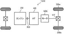
実施例のハイブリッド自動車20では、モータMGと駆動軸36との間に変速機46を備えるものとしたが、図7の変形例のハイブリッド自動車120に示すように、クラッチK0とモータMGとの間に変速機46を備えているものとしてもよい。
In the
実施例の主要な要素と課題を解決するための手段の欄に記載した発明の主要な要素との対応関係について説明する。実施例では、エンジン22が「エンジン」に相当し、モータMGが「モータ」に相当し、高圧バッテリ50が「第1バッテリ」に相当し、車載電気機器類66が「車載電気機器」に相当し、低圧バッテリ60が「第2バッテリ」に相当し、DC/DCコンバータ68が「DC/DCコンバータ」に相当し、オルタネータ62が「オルタネータ」に相当し、HVECU70が「制御手段」に相当する。
The correspondence between the main elements of the embodiment and the main elements of the invention described in the column of means for solving the problems will be described. In the embodiment, the
なお、実施例の主要な要素と課題を解決するための手段の欄に記載した発明の主要な要素との対応関係は、実施例が課題を解決するための手段の欄に記載した発明を実施するための形態を具体的に説明するための一例であることから、課題を解決するための手段の欄に記載した発明の要素を限定するものではない。即ち、課題を解決するための手段の欄に記載した発明についての解釈はその欄の記載に基づいて行なわれるべきものであり、実施例は課題を解決するための手段の欄に記載した発明の具体的な一例に過ぎないものである。 The correspondence between the main elements of the embodiment and the main elements of the invention described in the column of means for solving the problem is the same as that of the embodiment described in the column of means for solving the problem. Therefore, the elements of the invention described in the column of means for solving the problems are not limited. That is, the interpretation of the invention described in the column of means for solving the problems should be made based on the description of the column, and the examples are those of the invention described in the column of means for solving the problems. It is only a specific example.
以上、本発明を実施するための形態について実施例を用いて説明したが、本発明はこうした実施例に何等限定されるものではなく、本発明の要旨を逸脱しない範囲内において、種々なる形態で実施し得ることは勿論である。 As mentioned above, although the form for implementing this invention was demonstrated using the Example, this invention is not limited at all to such an Example, In the range which does not deviate from the summary of this invention, it is with various forms. Of course, it can be implemented.
本発明は、ハイブリッド車両の製造産業などに利用可能である。 The present invention is applicable to the hybrid vehicle manufacturing industry and the like.
20,120 ハイブリッド自動車、22 エンジン、24 エンジン用電子制御ユニット(エンジンECU)、26 クランクシャフト、27 スタータモータ、36 駆動軸、37 デファレンシャルギヤ、38a,38b 駆動輪、40 モータ用電子制御ユニット(モータECU)、41 インバータ、43 回転位置検出センサ、46 変速機、48 AT用電子制御ユニット(ATECU)、50 高圧バッテリ、51 システムメインリレー(SMR)、52 バッテリ用電子制御ユニット(バッテリECU)、54 高電圧系電力ライン、60 低圧バッテリ、60a 電圧センサ、61 ベルト、62 オルタネータ、62a 電流センサ、64 低電圧系電力ライン、66 車載電気機器類、68 DC/DCコンバータ、70 ハイブリッド用電子制御ユニット(HVECU)、80 イグニッションスイッチ、81 シフトレバー、82 シフトポジションセンサ、83 アクセルペダル、84 アクセルペダルポジションセンサ、85 ブレーキペダル、86 ブレーキペダルポジションセンサ、88 車速センサ、K0 クラッチ、MG モータ。 20,120 Hybrid vehicle, 22 engine, 24 engine electronic control unit (engine ECU), 26 crankshaft, 27 starter motor, 36 drive shaft, 37 differential gear, 38a, 38b drive wheel, 40 motor electronic control unit (motor) ECU), 41 inverter, 43 rotational position detection sensor, 46 transmission, 48 electronic control unit for AT (ATECU), 50 high voltage battery, 51 system main relay (SMR), 52 electronic control unit for battery (battery ECU), 54 High voltage system power line, 60 Low voltage battery, 60a Voltage sensor, 61 belt, 62 Alternator, 62a Current sensor, 64 Low voltage system power line, 66 Vehicle electrical equipment, 68 DC / DC converter, 70 Hybrid Electronic control unit (HV ECU), 80 ignition switch, 81 shift lever, 82 shift position sensor, 83 accelerator pedal, 84 accelerator pedal position sensor, 85 brake pedal, 86 brake pedal position sensor, 88 vehicle speed sensor, K0 clutch, MG motor.
Claims (1)
走行用の動力を出力可能なモータと、
前記モータが接続された第1電力ラインに接続された第1バッテリと、
車載電気機器と、
前記車載電気機器が接続された第2電力ラインに接続された第2バッテリと、
前記第1電力ラインの電力を変圧して前記第2電力ラインに供給するDC/DCコンバータと、
前記エンジンにより駆動され発電した電力を前記第2電力ラインに供給するオルタネータと、
前記第2バッテリの蓄電割合または前記第2バッテリの端子間電圧が第1閾値未満となったときには、前記オルタネータを停止して前記DC/DCコンバータから前記第2電力ラインに電力が供給されるよう前記DC/DCコンバータと前記オルタネータとを制御する第1制御を実行し、前記第1制御を実行している最中に前記第2バッテリの蓄電割合または前記第2バッテリの端子間電圧が前記第1閾値より小さい第2閾値から低下したときには、前記DC/DCコンバータからの電力と前記オルタネータからの電力とが前記第2電力ラインに供給されるよう前記DC/DCコンバータと前記オルタネータとを制御する第2制御を実行する制御手段と、
を備えるハイブリッド車両であって、
前記第2制御では、前記オルタネータについては、前記第2バッテリの定格電圧である所定電圧と前記オルタネータを効率良く駆動する電流範囲の下限以上の電流であり且つ前記DC/DCコンバータが供給可能な最大電流である所定電流とからなる所定駆動点で駆動するよう制御し、前記DC/DCコンバータについては前記第2バッテリの端子間電圧が前記定格電圧となるように前記DC/DCコンバータを制御する、
ことを特徴とするハイブリッド車両。 And an engine capable of outputting power for the run line,
A motor capable of outputting driving power;
A first battery connected to a first power line to which the motor is connected;
In-vehicle electrical equipment,
A second battery connected to a second power line to which the in-vehicle electric device is connected;
A DC / DC converter that transforms the power of the first power line and supplies it to the second power line;
An alternator for supplying the second power line with electric power driven by the engine;
When the storage ratio of the second battery or the voltage between the terminals of the second battery becomes less than the first threshold value , the alternator is stopped and power is supplied from the DC / DC converter to the second power line. The first control for controlling the DC / DC converter and the alternator is executed, and during the execution of the first control, the storage ratio of the second battery or the voltage between the terminals of the second battery is the first control . The DC / DC converter and the alternator are controlled so that the electric power from the DC / DC converter and the electric power from the alternator are supplied to the second electric power line when the voltage drops from a second threshold value smaller than one threshold value. Control means for executing the second control;
A hybrid vehicle comprising:
In the second control, the alternator has a predetermined voltage that is a rated voltage of the second battery and a current that is equal to or higher than a lower limit of a current range for efficiently driving the alternator and can be supplied by the DC / DC converter. Control to drive at a predetermined driving point consisting of a predetermined current that is a current, and control the DC / DC converter so that the voltage between the terminals of the second battery becomes the rated voltage for the DC / DC converter ,
A hybrid vehicle characterized by that.
Priority Applications (3)
| Application Number | Priority Date | Filing Date | Title |
|---|---|---|---|
| JP2015059339A JP6187516B2 (en) | 2015-03-23 | 2015-03-23 | Hybrid vehicle |
| CN201610161535.6A CN105984352B (en) | 2015-03-23 | 2016-03-21 | Hybrid vehicle |
| US15/076,935 US9937914B2 (en) | 2015-03-23 | 2016-03-22 | Hybrid vehicle |
Applications Claiming Priority (1)
| Application Number | Priority Date | Filing Date | Title |
|---|---|---|---|
| JP2015059339A JP6187516B2 (en) | 2015-03-23 | 2015-03-23 | Hybrid vehicle |
Publications (2)
| Publication Number | Publication Date |
|---|---|
| JP2016175621A JP2016175621A (en) | 2016-10-06 |
| JP6187516B2 true JP6187516B2 (en) | 2017-08-30 |
Family
ID=56974797
Family Applications (1)
| Application Number | Title | Priority Date | Filing Date |
|---|---|---|---|
| JP2015059339A Active JP6187516B2 (en) | 2015-03-23 | 2015-03-23 | Hybrid vehicle |
Country Status (3)
| Country | Link |
|---|---|
| US (1) | US9937914B2 (en) |
| JP (1) | JP6187516B2 (en) |
| CN (1) | CN105984352B (en) |
Families Citing this family (5)
| Publication number | Priority date | Publication date | Assignee | Title |
|---|---|---|---|---|
| US9647589B2 (en) * | 2015-06-22 | 2017-05-09 | Infineon Technologies Ag | Alternator with current measurement |
| DE102016217955A1 (en) * | 2016-09-20 | 2018-03-22 | Voith Patent Gmbh | Method for operating a hybrid vehicle |
| JP7102781B2 (en) * | 2018-02-28 | 2022-07-20 | 株式会社デンソー | Control device |
| IT201800006205A1 (en) * | 2018-06-11 | 2019-12-11 | ELECTRICAL POWER SYSTEM OF A VEHICLE WITH ELECTRIC PROPULSION | |
| JP7039088B1 (en) * | 2021-09-29 | 2022-03-22 | 株式会社アイディアル.ケー | Electric car |
Family Cites Families (8)
| Publication number | Priority date | Publication date | Assignee | Title |
|---|---|---|---|---|
| CN1291855C (en) * | 2002-12-08 | 2006-12-27 | 中国第一汽车集团公司 | Power system of double-motor hybrid-power automobile |
| JP4267565B2 (en) * | 2004-12-14 | 2009-05-27 | トヨタ自動車株式会社 | Power output device and automobile equipped with the same |
| JP2006280110A (en) * | 2005-03-29 | 2006-10-12 | Mitsubishi Fuso Truck & Bus Corp | Battery charging system for hybrid electric vehicle |
| JP4301197B2 (en) * | 2005-04-22 | 2009-07-22 | トヨタ自動車株式会社 | Vehicle control device |
| JP2007239511A (en) * | 2006-03-06 | 2007-09-20 | Denso Corp | Drive control device for vehicle |
| JP2008289303A (en) * | 2007-05-18 | 2008-11-27 | Toyota Motor Corp | Power controller |
| BRPI1014989A2 (en) * | 2009-04-27 | 2017-03-28 | Volvo Lastvagnar Ab | a battery charging system for a hybrid electric vehicle |
| JP2011160530A (en) * | 2010-01-29 | 2011-08-18 | Aisin Aw Co Ltd | Battery charging system |
-
2015
- 2015-03-23 JP JP2015059339A patent/JP6187516B2/en active Active
-
2016
- 2016-03-21 CN CN201610161535.6A patent/CN105984352B/en not_active Expired - Fee Related
- 2016-03-22 US US15/076,935 patent/US9937914B2/en active Active
Also Published As
| Publication number | Publication date |
|---|---|
| JP2016175621A (en) | 2016-10-06 |
| CN105984352A (en) | 2016-10-05 |
| US20160280208A1 (en) | 2016-09-29 |
| CN105984352B (en) | 2018-06-15 |
| US9937914B2 (en) | 2018-04-10 |
Similar Documents
| Publication | Publication Date | Title |
|---|---|---|
| JP6187516B2 (en) | Hybrid vehicle | |
| JP6260558B2 (en) | Hybrid car | |
| WO2005097536A1 (en) | Power output device and automobile | |
| JP2019156007A (en) | Control device for hybrid vehicle | |
| US9919695B2 (en) | Hybrid vehicle | |
| JP2019093986A (en) | Hybrid vehicle | |
| CN108216183B (en) | Apparatus and method for starting an engine of a mild hybrid electric vehicle | |
| JP5105064B2 (en) | Control device for hybrid vehicle | |
| US9682696B2 (en) | Hybrid vehicle | |
| CN108071541B (en) | Apparatus and method for starting engine of moderate hybrid electric vehicle | |
| JP6332173B2 (en) | Hybrid car | |
| JP6891486B2 (en) | Hybrid vehicle drive controller | |
| JP6729321B2 (en) | Hybrid car | |
| KR102371234B1 (en) | Appratus and method for extracting vibration of hybrid electric vehicle | |
| JP5655760B2 (en) | VEHICLE CHARGE CONTROL DEVICE AND VEHICLE CONTROL DEVICE | |
| JP2016132263A (en) | Hybrid automobile | |
| JP6160645B2 (en) | Hybrid car | |
| US10894539B2 (en) | Hybrid vehicle | |
| JP2017128212A (en) | Hybrid vehicle | |
| JP2011110996A (en) | Vehicle and control method therefor | |
| JP7147130B2 (en) | Drive control device for hybrid vehicle | |
| JP2016159878A (en) | Control device of hybrid vehicle | |
| JP6323378B2 (en) | Hybrid vehicle | |
| JP2016175560A (en) | Hybrid vehicle | |
| JP2016159707A (en) | Hybrid vehicle |
Legal Events
| Date | Code | Title | Description |
|---|---|---|---|
| A131 | Notification of reasons for refusal |
Free format text: JAPANESE INTERMEDIATE CODE: A131 Effective date: 20170314 |
|
| A521 | Written amendment |
Free format text: JAPANESE INTERMEDIATE CODE: A523 Effective date: 20170510 |
|
| TRDD | Decision of grant or rejection written | ||
| A01 | Written decision to grant a patent or to grant a registration (utility model) |
Free format text: JAPANESE INTERMEDIATE CODE: A01 Effective date: 20170704 |
|
| A61 | First payment of annual fees (during grant procedure) |
Free format text: JAPANESE INTERMEDIATE CODE: A61 Effective date: 20170717 |
|
| R151 | Written notification of patent or utility model registration |
Ref document number: 6187516 Country of ref document: JP Free format text: JAPANESE INTERMEDIATE CODE: R151 |