JP6160645B2 - Hybrid car - Google Patents
Hybrid car Download PDFInfo
- Publication number
- JP6160645B2 JP6160645B2 JP2015066893A JP2015066893A JP6160645B2 JP 6160645 B2 JP6160645 B2 JP 6160645B2 JP 2015066893 A JP2015066893 A JP 2015066893A JP 2015066893 A JP2015066893 A JP 2015066893A JP 6160645 B2 JP6160645 B2 JP 6160645B2
- Authority
- JP
- Japan
- Prior art keywords
- external power
- engine
- purge
- temperature
- power supply
- Prior art date
- Legal status (The legal status is an assumption and is not a legal conclusion. Google has not performed a legal analysis and makes no representation as to the accuracy of the status listed.)
- Expired - Fee Related
Links
- 238000010926 purge Methods 0.000 claims description 87
- 239000000446 fuel Substances 0.000 claims description 39
- 239000000498 cooling water Substances 0.000 claims description 14
- 239000002737 fuel gas Substances 0.000 claims description 11
- 239000002828 fuel tank Substances 0.000 claims description 8
- 238000004891 communication Methods 0.000 description 10
- 238000000034 method Methods 0.000 description 8
- 238000003860 storage Methods 0.000 description 6
- 239000003054 catalyst Substances 0.000 description 5
- 238000002485 combustion reaction Methods 0.000 description 5
- 238000010586 diagram Methods 0.000 description 5
- MWUXSHHQAYIFBG-UHFFFAOYSA-N nitrogen oxide Inorganic materials O=[N] MWUXSHHQAYIFBG-UHFFFAOYSA-N 0.000 description 5
- 238000000746 purification Methods 0.000 description 5
- 239000002826 coolant Substances 0.000 description 4
- 238000007599 discharging Methods 0.000 description 4
- 238000001179 sorption measurement Methods 0.000 description 4
- XLYOFNOQVPJJNP-UHFFFAOYSA-N water Substances O XLYOFNOQVPJJNP-UHFFFAOYSA-N 0.000 description 4
- QVGXLLKOCUKJST-UHFFFAOYSA-N atomic oxygen Chemical group [O] QVGXLLKOCUKJST-UHFFFAOYSA-N 0.000 description 3
- 238000001514 detection method Methods 0.000 description 3
- 239000003502 gasoline Substances 0.000 description 3
- 238000002347 injection Methods 0.000 description 3
- 239000007924 injection Substances 0.000 description 3
- 239000000203 mixture Substances 0.000 description 3
- 239000001301 oxygen Substances 0.000 description 3
- 229910052760 oxygen Inorganic materials 0.000 description 3
- OKTJSMMVPCPJKN-UHFFFAOYSA-N Carbon Chemical compound [C] OKTJSMMVPCPJKN-UHFFFAOYSA-N 0.000 description 2
- UGFAIRIUMAVXCW-UHFFFAOYSA-N Carbon monoxide Chemical compound [O+]#[C-] UGFAIRIUMAVXCW-UHFFFAOYSA-N 0.000 description 2
- 230000005540 biological transmission Effects 0.000 description 2
- 229910002091 carbon monoxide Inorganic materials 0.000 description 2
- 229930195733 hydrocarbon Natural products 0.000 description 2
- 150000002430 hydrocarbons Chemical class 0.000 description 2
- 230000007935 neutral effect Effects 0.000 description 2
- 230000001360 synchronised effect Effects 0.000 description 2
- HBBGRARXTFLTSG-UHFFFAOYSA-N Lithium ion Chemical compound [Li+] HBBGRARXTFLTSG-UHFFFAOYSA-N 0.000 description 1
- 239000003463 adsorbent Substances 0.000 description 1
- 238000006243 chemical reaction Methods 0.000 description 1
- 230000007423 decrease Effects 0.000 description 1
- 238000010892 electric spark Methods 0.000 description 1
- 239000007789 gas Substances 0.000 description 1
- 229910001416 lithium ion Inorganic materials 0.000 description 1
- 238000004519 manufacturing process Methods 0.000 description 1
- 230000004048 modification Effects 0.000 description 1
- 238000012986 modification Methods 0.000 description 1
- 238000010248 power generation Methods 0.000 description 1
Images


Classifications
-
- F—MECHANICAL ENGINEERING; LIGHTING; HEATING; WEAPONS; BLASTING
- F02—COMBUSTION ENGINES; HOT-GAS OR COMBUSTION-PRODUCT ENGINE PLANTS
- F02M—SUPPLYING COMBUSTION ENGINES IN GENERAL WITH COMBUSTIBLE MIXTURES OR CONSTITUENTS THEREOF
- F02M25/00—Engine-pertinent apparatus for adding non-fuel substances or small quantities of secondary fuel to combustion-air, main fuel or fuel-air mixture
- F02M25/08—Engine-pertinent apparatus for adding non-fuel substances or small quantities of secondary fuel to combustion-air, main fuel or fuel-air mixture adding fuel vapours drawn from engine fuel reservoir
-
- B—PERFORMING OPERATIONS; TRANSPORTING
- B60—VEHICLES IN GENERAL
- B60K—ARRANGEMENT OR MOUNTING OF PROPULSION UNITS OR OF TRANSMISSIONS IN VEHICLES; ARRANGEMENT OR MOUNTING OF PLURAL DIVERSE PRIME-MOVERS IN VEHICLES; AUXILIARY DRIVES FOR VEHICLES; INSTRUMENTATION OR DASHBOARDS FOR VEHICLES; ARRANGEMENTS IN CONNECTION WITH COOLING, AIR INTAKE, GAS EXHAUST OR FUEL SUPPLY OF PROPULSION UNITS IN VEHICLES
- B60K6/00—Arrangement or mounting of plural diverse prime-movers for mutual or common propulsion, e.g. hybrid propulsion systems comprising electric motors and internal combustion engines ; Control systems therefor, i.e. systems controlling two or more prime movers, or controlling one of these prime movers and any of the transmission, drive or drive units Informative references: mechanical gearings with secondary electric drive F16H3/72; arrangements for handling mechanical energy structurally associated with the dynamo-electric machine H02K7/00; machines comprising structurally interrelated motor and generator parts H02K51/00; dynamo-electric machines not otherwise provided for in H02K see H02K99/00
- B60K6/20—Arrangement or mounting of plural diverse prime-movers for mutual or common propulsion, e.g. hybrid propulsion systems comprising electric motors and internal combustion engines ; Control systems therefor, i.e. systems controlling two or more prime movers, or controlling one of these prime movers and any of the transmission, drive or drive units Informative references: mechanical gearings with secondary electric drive F16H3/72; arrangements for handling mechanical energy structurally associated with the dynamo-electric machine H02K7/00; machines comprising structurally interrelated motor and generator parts H02K51/00; dynamo-electric machines not otherwise provided for in H02K see H02K99/00 the prime-movers consisting of electric motors and internal combustion engines, e.g. HEVs
- B60K6/42—Arrangement or mounting of plural diverse prime-movers for mutual or common propulsion, e.g. hybrid propulsion systems comprising electric motors and internal combustion engines ; Control systems therefor, i.e. systems controlling two or more prime movers, or controlling one of these prime movers and any of the transmission, drive or drive units Informative references: mechanical gearings with secondary electric drive F16H3/72; arrangements for handling mechanical energy structurally associated with the dynamo-electric machine H02K7/00; machines comprising structurally interrelated motor and generator parts H02K51/00; dynamo-electric machines not otherwise provided for in H02K see H02K99/00 the prime-movers consisting of electric motors and internal combustion engines, e.g. HEVs characterised by the architecture of the hybrid electric vehicle
- B60K6/44—Series-parallel type
- B60K6/445—Differential gearing distribution type
-
- B—PERFORMING OPERATIONS; TRANSPORTING
- B60—VEHICLES IN GENERAL
- B60L—PROPULSION OF ELECTRICALLY-PROPELLED VEHICLES; SUPPLYING ELECTRIC POWER FOR AUXILIARY EQUIPMENT OF ELECTRICALLY-PROPELLED VEHICLES; ELECTRODYNAMIC BRAKE SYSTEMS FOR VEHICLES IN GENERAL; MAGNETIC SUSPENSION OR LEVITATION FOR VEHICLES; MONITORING OPERATING VARIABLES OF ELECTRICALLY-PROPELLED VEHICLES; ELECTRIC SAFETY DEVICES FOR ELECTRICALLY-PROPELLED VEHICLES
- B60L50/00—Electric propulsion with power supplied within the vehicle
- B60L50/50—Electric propulsion with power supplied within the vehicle using propulsion power supplied by batteries or fuel cells
- B60L50/60—Electric propulsion with power supplied within the vehicle using propulsion power supplied by batteries or fuel cells using power supplied by batteries
- B60L50/61—Electric propulsion with power supplied within the vehicle using propulsion power supplied by batteries or fuel cells using power supplied by batteries by batteries charged by engine-driven generators, e.g. series hybrid electric vehicles
- B60L50/62—Electric propulsion with power supplied within the vehicle using propulsion power supplied by batteries or fuel cells using power supplied by batteries by batteries charged by engine-driven generators, e.g. series hybrid electric vehicles charged by low-power generators primarily intended to support the batteries, e.g. range extenders
-
- B—PERFORMING OPERATIONS; TRANSPORTING
- B60—VEHICLES IN GENERAL
- B60L—PROPULSION OF ELECTRICALLY-PROPELLED VEHICLES; SUPPLYING ELECTRIC POWER FOR AUXILIARY EQUIPMENT OF ELECTRICALLY-PROPELLED VEHICLES; ELECTRODYNAMIC BRAKE SYSTEMS FOR VEHICLES IN GENERAL; MAGNETIC SUSPENSION OR LEVITATION FOR VEHICLES; MONITORING OPERATING VARIABLES OF ELECTRICALLY-PROPELLED VEHICLES; ELECTRIC SAFETY DEVICES FOR ELECTRICALLY-PROPELLED VEHICLES
- B60L55/00—Arrangements for supplying energy stored within a vehicle to a power network, i.e. vehicle-to-grid [V2G] arrangements
-
- B—PERFORMING OPERATIONS; TRANSPORTING
- B60—VEHICLES IN GENERAL
- B60W—CONJOINT CONTROL OF VEHICLE SUB-UNITS OF DIFFERENT TYPE OR DIFFERENT FUNCTION; CONTROL SYSTEMS SPECIALLY ADAPTED FOR HYBRID VEHICLES; ROAD VEHICLE DRIVE CONTROL SYSTEMS FOR PURPOSES NOT RELATED TO THE CONTROL OF A PARTICULAR SUB-UNIT
- B60W10/00—Conjoint control of vehicle sub-units of different type or different function
- B60W10/04—Conjoint control of vehicle sub-units of different type or different function including control of propulsion units
- B60W10/06—Conjoint control of vehicle sub-units of different type or different function including control of propulsion units including control of combustion engines
-
- B—PERFORMING OPERATIONS; TRANSPORTING
- B60—VEHICLES IN GENERAL
- B60W—CONJOINT CONTROL OF VEHICLE SUB-UNITS OF DIFFERENT TYPE OR DIFFERENT FUNCTION; CONTROL SYSTEMS SPECIALLY ADAPTED FOR HYBRID VEHICLES; ROAD VEHICLE DRIVE CONTROL SYSTEMS FOR PURPOSES NOT RELATED TO THE CONTROL OF A PARTICULAR SUB-UNIT
- B60W10/00—Conjoint control of vehicle sub-units of different type or different function
- B60W10/04—Conjoint control of vehicle sub-units of different type or different function including control of propulsion units
- B60W10/08—Conjoint control of vehicle sub-units of different type or different function including control of propulsion units including control of electric propulsion units, e.g. motors or generators
-
- B—PERFORMING OPERATIONS; TRANSPORTING
- B60—VEHICLES IN GENERAL
- B60W—CONJOINT CONTROL OF VEHICLE SUB-UNITS OF DIFFERENT TYPE OR DIFFERENT FUNCTION; CONTROL SYSTEMS SPECIALLY ADAPTED FOR HYBRID VEHICLES; ROAD VEHICLE DRIVE CONTROL SYSTEMS FOR PURPOSES NOT RELATED TO THE CONTROL OF A PARTICULAR SUB-UNIT
- B60W10/00—Conjoint control of vehicle sub-units of different type or different function
- B60W10/24—Conjoint control of vehicle sub-units of different type or different function including control of energy storage means
- B60W10/26—Conjoint control of vehicle sub-units of different type or different function including control of energy storage means for electrical energy, e.g. batteries or capacitors
-
- B—PERFORMING OPERATIONS; TRANSPORTING
- B60—VEHICLES IN GENERAL
- B60W—CONJOINT CONTROL OF VEHICLE SUB-UNITS OF DIFFERENT TYPE OR DIFFERENT FUNCTION; CONTROL SYSTEMS SPECIALLY ADAPTED FOR HYBRID VEHICLES; ROAD VEHICLE DRIVE CONTROL SYSTEMS FOR PURPOSES NOT RELATED TO THE CONTROL OF A PARTICULAR SUB-UNIT
- B60W20/00—Control systems specially adapted for hybrid vehicles
- B60W20/10—Controlling the power contribution of each of the prime movers to meet required power demand
- B60W20/15—Control strategies specially adapted for achieving a particular effect
- B60W20/16—Control strategies specially adapted for achieving a particular effect for reducing engine exhaust emissions
-
- B—PERFORMING OPERATIONS; TRANSPORTING
- B60—VEHICLES IN GENERAL
- B60W—CONJOINT CONTROL OF VEHICLE SUB-UNITS OF DIFFERENT TYPE OR DIFFERENT FUNCTION; CONTROL SYSTEMS SPECIALLY ADAPTED FOR HYBRID VEHICLES; ROAD VEHICLE DRIVE CONTROL SYSTEMS FOR PURPOSES NOT RELATED TO THE CONTROL OF A PARTICULAR SUB-UNIT
- B60W30/00—Purposes of road vehicle drive control systems not related to the control of a particular sub-unit, e.g. of systems using conjoint control of vehicle sub-units, or advanced driver assistance systems for ensuring comfort, stability and safety or drive control systems for propelling or retarding the vehicle
- B60W30/18—Propelling the vehicle
- B60W30/18009—Propelling the vehicle related to particular drive situations
- B60W30/18054—Propelling the vehicle related to particular drive situations at stand still, e.g. engine in idling state
-
- F—MECHANICAL ENGINEERING; LIGHTING; HEATING; WEAPONS; BLASTING
- F02—COMBUSTION ENGINES; HOT-GAS OR COMBUSTION-PRODUCT ENGINE PLANTS
- F02D—CONTROLLING COMBUSTION ENGINES
- F02D41/00—Electrical control of supply of combustible mixture or its constituents
- F02D41/0025—Controlling engines characterised by use of non-liquid fuels, pluralities of fuels, or non-fuel substances added to the combustible mixtures
- F02D41/003—Adding fuel vapours, e.g. drawn from engine fuel reservoir
- F02D41/0032—Controlling the purging of the canister as a function of the engine operating conditions
- F02D41/004—Control of the valve or purge actuator, e.g. duty cycle, closed loop control of position
-
- F—MECHANICAL ENGINEERING; LIGHTING; HEATING; WEAPONS; BLASTING
- F02—COMBUSTION ENGINES; HOT-GAS OR COMBUSTION-PRODUCT ENGINE PLANTS
- F02M—SUPPLYING COMBUSTION ENGINES IN GENERAL WITH COMBUSTIBLE MIXTURES OR CONSTITUENTS THEREOF
- F02M25/00—Engine-pertinent apparatus for adding non-fuel substances or small quantities of secondary fuel to combustion-air, main fuel or fuel-air mixture
- F02M25/08—Engine-pertinent apparatus for adding non-fuel substances or small quantities of secondary fuel to combustion-air, main fuel or fuel-air mixture adding fuel vapours drawn from engine fuel reservoir
- F02M25/0836—Arrangement of valves controlling the admission of fuel vapour to an engine, e.g. valve being disposed between fuel tank or absorption canister and intake manifold
-
- B—PERFORMING OPERATIONS; TRANSPORTING
- B60—VEHICLES IN GENERAL
- B60K—ARRANGEMENT OR MOUNTING OF PROPULSION UNITS OR OF TRANSMISSIONS IN VEHICLES; ARRANGEMENT OR MOUNTING OF PLURAL DIVERSE PRIME-MOVERS IN VEHICLES; AUXILIARY DRIVES FOR VEHICLES; INSTRUMENTATION OR DASHBOARDS FOR VEHICLES; ARRANGEMENTS IN CONNECTION WITH COOLING, AIR INTAKE, GAS EXHAUST OR FUEL SUPPLY OF PROPULSION UNITS IN VEHICLES
- B60K15/00—Arrangement in connection with fuel supply of combustion engines or other fuel consuming energy converters, e.g. fuel cells; Mounting or construction of fuel tanks
- B60K15/03—Fuel tanks
- B60K15/035—Fuel tanks characterised by venting means
- B60K2015/03561—Venting means working at specific times
-
- B—PERFORMING OPERATIONS; TRANSPORTING
- B60—VEHICLES IN GENERAL
- B60L—PROPULSION OF ELECTRICALLY-PROPELLED VEHICLES; SUPPLYING ELECTRIC POWER FOR AUXILIARY EQUIPMENT OF ELECTRICALLY-PROPELLED VEHICLES; ELECTRODYNAMIC BRAKE SYSTEMS FOR VEHICLES IN GENERAL; MAGNETIC SUSPENSION OR LEVITATION FOR VEHICLES; MONITORING OPERATING VARIABLES OF ELECTRICALLY-PROPELLED VEHICLES; ELECTRIC SAFETY DEVICES FOR ELECTRICALLY-PROPELLED VEHICLES
- B60L2240/00—Control parameters of input or output; Target parameters
- B60L2240/10—Vehicle control parameters
- B60L2240/36—Temperature of vehicle components or parts
-
- B—PERFORMING OPERATIONS; TRANSPORTING
- B60—VEHICLES IN GENERAL
- B60L—PROPULSION OF ELECTRICALLY-PROPELLED VEHICLES; SUPPLYING ELECTRIC POWER FOR AUXILIARY EQUIPMENT OF ELECTRICALLY-PROPELLED VEHICLES; ELECTRODYNAMIC BRAKE SYSTEMS FOR VEHICLES IN GENERAL; MAGNETIC SUSPENSION OR LEVITATION FOR VEHICLES; MONITORING OPERATING VARIABLES OF ELECTRICALLY-PROPELLED VEHICLES; ELECTRIC SAFETY DEVICES FOR ELECTRICALLY-PROPELLED VEHICLES
- B60L2240/00—Control parameters of input or output; Target parameters
- B60L2240/40—Drive Train control parameters
- B60L2240/54—Drive Train control parameters related to batteries
- B60L2240/547—Voltage
-
- B—PERFORMING OPERATIONS; TRANSPORTING
- B60—VEHICLES IN GENERAL
- B60L—PROPULSION OF ELECTRICALLY-PROPELLED VEHICLES; SUPPLYING ELECTRIC POWER FOR AUXILIARY EQUIPMENT OF ELECTRICALLY-PROPELLED VEHICLES; ELECTRODYNAMIC BRAKE SYSTEMS FOR VEHICLES IN GENERAL; MAGNETIC SUSPENSION OR LEVITATION FOR VEHICLES; MONITORING OPERATING VARIABLES OF ELECTRICALLY-PROPELLED VEHICLES; ELECTRIC SAFETY DEVICES FOR ELECTRICALLY-PROPELLED VEHICLES
- B60L2240/00—Control parameters of input or output; Target parameters
- B60L2240/40—Drive Train control parameters
- B60L2240/54—Drive Train control parameters related to batteries
- B60L2240/549—Current
-
- B—PERFORMING OPERATIONS; TRANSPORTING
- B60—VEHICLES IN GENERAL
- B60W—CONJOINT CONTROL OF VEHICLE SUB-UNITS OF DIFFERENT TYPE OR DIFFERENT FUNCTION; CONTROL SYSTEMS SPECIALLY ADAPTED FOR HYBRID VEHICLES; ROAD VEHICLE DRIVE CONTROL SYSTEMS FOR PURPOSES NOT RELATED TO THE CONTROL OF A PARTICULAR SUB-UNIT
- B60W2510/00—Input parameters relating to a particular sub-units
- B60W2510/08—Electric propulsion units
- B60W2510/087—Temperature
-
- B—PERFORMING OPERATIONS; TRANSPORTING
- B60—VEHICLES IN GENERAL
- B60W—CONJOINT CONTROL OF VEHICLE SUB-UNITS OF DIFFERENT TYPE OR DIFFERENT FUNCTION; CONTROL SYSTEMS SPECIALLY ADAPTED FOR HYBRID VEHICLES; ROAD VEHICLE DRIVE CONTROL SYSTEMS FOR PURPOSES NOT RELATED TO THE CONTROL OF A PARTICULAR SUB-UNIT
- B60W2510/00—Input parameters relating to a particular sub-units
- B60W2510/24—Energy storage means
- B60W2510/242—Energy storage means for electrical energy
- B60W2510/244—Charge state
-
- F—MECHANICAL ENGINEERING; LIGHTING; HEATING; WEAPONS; BLASTING
- F02—COMBUSTION ENGINES; HOT-GAS OR COMBUSTION-PRODUCT ENGINE PLANTS
- F02D—CONTROLLING COMBUSTION ENGINES
- F02D2200/00—Input parameters for engine control
- F02D2200/02—Input parameters for engine control the parameters being related to the engine
- F02D2200/021—Engine temperature
-
- Y—GENERAL TAGGING OF NEW TECHNOLOGICAL DEVELOPMENTS; GENERAL TAGGING OF CROSS-SECTIONAL TECHNOLOGIES SPANNING OVER SEVERAL SECTIONS OF THE IPC; TECHNICAL SUBJECTS COVERED BY FORMER USPC CROSS-REFERENCE ART COLLECTIONS [XRACs] AND DIGESTS
- Y02—TECHNOLOGIES OR APPLICATIONS FOR MITIGATION OR ADAPTATION AGAINST CLIMATE CHANGE
- Y02E—REDUCTION OF GREENHOUSE GAS [GHG] EMISSIONS, RELATED TO ENERGY GENERATION, TRANSMISSION OR DISTRIBUTION
- Y02E60/00—Enabling technologies; Technologies with a potential or indirect contribution to GHG emissions mitigation
-
- Y—GENERAL TAGGING OF NEW TECHNOLOGICAL DEVELOPMENTS; GENERAL TAGGING OF CROSS-SECTIONAL TECHNOLOGIES SPANNING OVER SEVERAL SECTIONS OF THE IPC; TECHNICAL SUBJECTS COVERED BY FORMER USPC CROSS-REFERENCE ART COLLECTIONS [XRACs] AND DIGESTS
- Y02—TECHNOLOGIES OR APPLICATIONS FOR MITIGATION OR ADAPTATION AGAINST CLIMATE CHANGE
- Y02T—CLIMATE CHANGE MITIGATION TECHNOLOGIES RELATED TO TRANSPORTATION
- Y02T10/00—Road transport of goods or passengers
- Y02T10/60—Other road transportation technologies with climate change mitigation effect
- Y02T10/62—Hybrid vehicles
-
- Y—GENERAL TAGGING OF NEW TECHNOLOGICAL DEVELOPMENTS; GENERAL TAGGING OF CROSS-SECTIONAL TECHNOLOGIES SPANNING OVER SEVERAL SECTIONS OF THE IPC; TECHNICAL SUBJECTS COVERED BY FORMER USPC CROSS-REFERENCE ART COLLECTIONS [XRACs] AND DIGESTS
- Y02—TECHNOLOGIES OR APPLICATIONS FOR MITIGATION OR ADAPTATION AGAINST CLIMATE CHANGE
- Y02T—CLIMATE CHANGE MITIGATION TECHNOLOGIES RELATED TO TRANSPORTATION
- Y02T10/00—Road transport of goods or passengers
- Y02T10/60—Other road transportation technologies with climate change mitigation effect
- Y02T10/70—Energy storage systems for electromobility, e.g. batteries
-
- Y—GENERAL TAGGING OF NEW TECHNOLOGICAL DEVELOPMENTS; GENERAL TAGGING OF CROSS-SECTIONAL TECHNOLOGIES SPANNING OVER SEVERAL SECTIONS OF THE IPC; TECHNICAL SUBJECTS COVERED BY FORMER USPC CROSS-REFERENCE ART COLLECTIONS [XRACs] AND DIGESTS
- Y02—TECHNOLOGIES OR APPLICATIONS FOR MITIGATION OR ADAPTATION AGAINST CLIMATE CHANGE
- Y02T—CLIMATE CHANGE MITIGATION TECHNOLOGIES RELATED TO TRANSPORTATION
- Y02T10/00—Road transport of goods or passengers
- Y02T10/60—Other road transportation technologies with climate change mitigation effect
- Y02T10/7072—Electromobility specific charging systems or methods for batteries, ultracapacitors, supercapacitors or double-layer capacitors
-
- Y—GENERAL TAGGING OF NEW TECHNOLOGICAL DEVELOPMENTS; GENERAL TAGGING OF CROSS-SECTIONAL TECHNOLOGIES SPANNING OVER SEVERAL SECTIONS OF THE IPC; TECHNICAL SUBJECTS COVERED BY FORMER USPC CROSS-REFERENCE ART COLLECTIONS [XRACs] AND DIGESTS
- Y02—TECHNOLOGIES OR APPLICATIONS FOR MITIGATION OR ADAPTATION AGAINST CLIMATE CHANGE
- Y02T—CLIMATE CHANGE MITIGATION TECHNOLOGIES RELATED TO TRANSPORTATION
- Y02T90/00—Enabling technologies or technologies with a potential or indirect contribution to GHG emissions mitigation
- Y02T90/10—Technologies relating to charging of electric vehicles
- Y02T90/12—Electric charging stations
-
- Y—GENERAL TAGGING OF NEW TECHNOLOGICAL DEVELOPMENTS; GENERAL TAGGING OF CROSS-SECTIONAL TECHNOLOGIES SPANNING OVER SEVERAL SECTIONS OF THE IPC; TECHNICAL SUBJECTS COVERED BY FORMER USPC CROSS-REFERENCE ART COLLECTIONS [XRACs] AND DIGESTS
- Y02—TECHNOLOGIES OR APPLICATIONS FOR MITIGATION OR ADAPTATION AGAINST CLIMATE CHANGE
- Y02T—CLIMATE CHANGE MITIGATION TECHNOLOGIES RELATED TO TRANSPORTATION
- Y02T90/00—Enabling technologies or technologies with a potential or indirect contribution to GHG emissions mitigation
- Y02T90/10—Technologies relating to charging of electric vehicles
- Y02T90/14—Plug-in electric vehicles
-
- Y—GENERAL TAGGING OF NEW TECHNOLOGICAL DEVELOPMENTS; GENERAL TAGGING OF CROSS-SECTIONAL TECHNOLOGIES SPANNING OVER SEVERAL SECTIONS OF THE IPC; TECHNICAL SUBJECTS COVERED BY FORMER USPC CROSS-REFERENCE ART COLLECTIONS [XRACs] AND DIGESTS
- Y02—TECHNOLOGIES OR APPLICATIONS FOR MITIGATION OR ADAPTATION AGAINST CLIMATE CHANGE
- Y02T—CLIMATE CHANGE MITIGATION TECHNOLOGIES RELATED TO TRANSPORTATION
- Y02T90/00—Enabling technologies or technologies with a potential or indirect contribution to GHG emissions mitigation
- Y02T90/10—Technologies relating to charging of electric vehicles
- Y02T90/16—Information or communication technologies improving the operation of electric vehicles
-
- Y—GENERAL TAGGING OF NEW TECHNOLOGICAL DEVELOPMENTS; GENERAL TAGGING OF CROSS-SECTIONAL TECHNOLOGIES SPANNING OVER SEVERAL SECTIONS OF THE IPC; TECHNICAL SUBJECTS COVERED BY FORMER USPC CROSS-REFERENCE ART COLLECTIONS [XRACs] AND DIGESTS
- Y04—INFORMATION OR COMMUNICATION TECHNOLOGIES HAVING AN IMPACT ON OTHER TECHNOLOGY AREAS
- Y04S—SYSTEMS INTEGRATING TECHNOLOGIES RELATED TO POWER NETWORK OPERATION, COMMUNICATION OR INFORMATION TECHNOLOGIES FOR IMPROVING THE ELECTRICAL POWER GENERATION, TRANSMISSION, DISTRIBUTION, MANAGEMENT OR USAGE, i.e. SMART GRIDS
- Y04S10/00—Systems supporting electrical power generation, transmission or distribution
- Y04S10/12—Monitoring or controlling equipment for energy generation units, e.g. distributed energy generation [DER] or load-side generation
- Y04S10/126—Monitoring or controlling equipment for energy generation units, e.g. distributed energy generation [DER] or load-side generation the energy generation units being or involving electric vehicles [EV] or hybrid vehicles [HEV], i.e. power aggregation of EV or HEV, vehicle to grid arrangements [V2G]
-
- Y—GENERAL TAGGING OF NEW TECHNOLOGICAL DEVELOPMENTS; GENERAL TAGGING OF CROSS-SECTIONAL TECHNOLOGIES SPANNING OVER SEVERAL SECTIONS OF THE IPC; TECHNICAL SUBJECTS COVERED BY FORMER USPC CROSS-REFERENCE ART COLLECTIONS [XRACs] AND DIGESTS
- Y10—TECHNICAL SUBJECTS COVERED BY FORMER USPC
- Y10S—TECHNICAL SUBJECTS COVERED BY FORMER USPC CROSS-REFERENCE ART COLLECTIONS [XRACs] AND DIGESTS
- Y10S903/00—Hybrid electric vehicles, HEVS
- Y10S903/902—Prime movers comprising electrical and internal combustion motors
- Y10S903/903—Prime movers comprising electrical and internal combustion motors having energy storing means, e.g. battery, capacitor
Description
本発明は、ハイブリッド自動車に関し、詳しくは、外部機器に外部給電可能なハイブリッド自動車に関する。 The present invention relates to a hybrid vehicle, and more particularly to a hybrid vehicle capable of externally supplying power to an external device.
従来、この種のハイブリッド自動車としては、外部電源からの充電が可能なプラグインハイブリッド自動車において、キャニスタでの蒸発燃料の吸着状態を推定し、推定した吸着状態と走行負荷とに基づいて電動走行からエンジンを駆動するハイブリッド走行に切り替えるものが提案されている(例えば、特許文献1参照)。このプラグインハイブリッド自動車では、キャニスタの蒸発燃料の吸着状態に基づいてハイブリッド走行することにより、エンジンの駆動時間や頻度が少ないプラグインハイブリッド自動車でも、キャニスタに吸着した蒸発燃料のエンジンへのパージを確実に行なうことができるようにしている。なお、この自動車では、外気温度に基づいてキャニスタの蒸発燃料の吸着状態を推定している。 Conventionally, as this type of hybrid vehicle, in a plug-in hybrid vehicle that can be charged from an external power source, the adsorption state of the evaporated fuel in the canister is estimated, and from the electric traveling based on the estimated adsorption state and the running load A switch to hybrid driving for driving the engine has been proposed (see, for example, Patent Document 1). In this plug-in hybrid vehicle, hybrid driving based on the adsorption state of the evaporated fuel in the canister ensures that the evaporated fuel adsorbed in the canister is purged to the engine even in a plug-in hybrid vehicle with a low engine drive time and frequency. To be able to do it. In this automobile, the adsorption state of the evaporated fuel in the canister is estimated based on the outside air temperature.
ハイブリッド自動車には、外部電源からの充電を行なうだけでなく、車外の外部機器に給電するものもある。この場合、外部給電によりバッテリの蓄電割合SOCが低くなるとエンジンを始動してエンジンからの動力を用いて発電機により発電してバッテリを充電する。このような外部給電中のエンジン駆動は、ある程度のバッテリの充電のためであることから、エンジンの運転時間が短い場合が多く、キャニスタに吸着した蒸発燃料をエンジンにパージする実行条件が成立しない場合も多い。一方、外部給電中は停車しているため、走行中に比して、キャニスタパージによるドライバビリティに与える影響は小さい。 Some hybrid vehicles not only charge from an external power source but also supply power to external devices outside the vehicle. In this case, when the storage ratio SOC of the battery decreases due to external power feeding, the engine is started, and the battery is charged by generating electric power using a power generator from the engine. Since the engine drive during external power supply is for charging the battery to some extent, the engine operation time is often short, and the execution condition for purging the evaporated fuel adsorbed on the canister to the engine is not satisfied There are also many. On the other hand, since the vehicle is stopped during external power feeding, the influence on the drivability due to the canister purge is smaller than that during traveling.
本発明のハイブリッド自動車は、キャニスタに吸着した蒸発燃料をパージする機会を多くすることを主目的とする。 The main purpose of the hybrid vehicle of the present invention is to increase the opportunity to purge the evaporated fuel adsorbed on the canister.
本発明のハイブリッド自動車は、上述の主目的を達成するために以下の手段を採った。 The hybrid vehicle of the present invention employs the following means in order to achieve the main object described above.
本発明のハイブリッド自動車は、
燃料タンクに貯留された燃料の供給を受けて動力を出力するエンジンと、
前記燃料タンク内で発生した蒸発燃料を吸着するキャニスタと、
前記キャニスタで吸着した蒸発燃料を含む蒸発燃料ガスを前記エンジンの吸気管へ供給する供給管に取り付けられたパージバルブと、
前記蒸発燃料ガスが前記吸気管へ供給されるよう前記パージバルブを開閉制御する蒸発燃料用制御手段と、
前記エンジンからの動力を用いて発電する発電機と、
前記発電機に電力ラインを介して接続されたバッテリと、
前記電力ラインの電力を外部機器に供給する外部給電を行なう外部給電装置と、
を備えるハイブリッド自動車であって、
前記蒸発燃料用制御手段は、前記外部給電装置により外部給電しているときには、前記外部給電装置により外部給電していないときに比して、前記蒸発燃料ガスの前記吸気管へ供給されやすくなる実行条件を用いて前記パージバルブを開閉制御する手段である、
ことを特徴とする。
The hybrid vehicle of the present invention
An engine that outputs power by receiving supply of fuel stored in a fuel tank;
A canister that adsorbs the evaporated fuel generated in the fuel tank;
A purge valve attached to a supply pipe for supplying evaporated fuel gas containing evaporated fuel adsorbed by the canister to the intake pipe of the engine;
Evaporative fuel control means for opening and closing the purge valve so that the evaporative fuel gas is supplied to the intake pipe;
A generator that generates power using power from the engine;
A battery connected to the generator via a power line;
An external power supply device for performing external power supply for supplying power from the power line to an external device;
A hybrid vehicle comprising:
The evaporative fuel control means is more likely to supply the evaporative fuel gas to the intake pipe when external power is supplied from the external power supply device than when external power is not supplied from the external power supply device. Means for controlling the opening and closing of the purge valve using conditions,
It is characterized by that.
この本発明のハイブリッド自動車では、外部給電装置により外部給電しているときには、外部給電していないときに比して、キャニスタからの蒸発燃料ガスのエンジンの吸気管への供給が実行されやすくなる実行条件を用いて、蒸発燃料ガスをエンジンの吸気管へ供給する供給管に取り付けられたパージバルブを開閉制御する。これにより、外部給電装置により外部給電しているときには、キャニスタからの蒸発燃料ガスの吸気管への供給(いわゆるキャニスタパージ)が実行されやすくなる。この結果、キャニスタパージを行なう機会を多くすることができ、エボパエミッション性能を向上させることができる。また、外部給電後にキャニスタパージのためにエンジンの運転時間が長くなるのを抑制することができる。 In the hybrid vehicle of the present invention, when the external power feeding is performed by the external power feeding device, the supply of the evaporated fuel gas from the canister to the engine intake pipe is more easily performed than when the external power feeding is not performed. Using the conditions, the purge valve attached to the supply pipe that supplies the evaporated fuel gas to the intake pipe of the engine is controlled to open and close. As a result, when external power is supplied by the external power supply device, supply of evaporated fuel gas from the canister to the intake pipe (so-called canister purge) is facilitated. As a result, the opportunity to perform canister purge can be increased and the evapa emission performance can be improved. In addition, it is possible to prevent the engine operating time from becoming longer due to the canister purge after external power feeding.
こうした本発明のハイブリッド自動車において、前記実行条件は、前記外部給電装置により外部給電していないときには前記エンジンの冷却水の温度が第1温度以上である条件であり、前記外部給電装置により外部給電しているときには前記エンジンの冷却水の温度が前記第1温度より低い第2温度以上である条件であるものとしてもよい。こうすれば、外部給電装置により外部給電しているときには、外部給電していないときに比して、エンジンを始動してから早期にキャニスタパージを実行することができる。 In such a hybrid vehicle of the present invention, the execution condition is a condition in which the temperature of the cooling water of the engine is equal to or higher than the first temperature when external power is not supplied by the external power supply device, and external power is supplied by the external power supply device. The engine cooling water temperature may be equal to or higher than a second temperature lower than the first temperature. In this way, when external power is supplied by the external power supply device, canister purge can be executed earlier after the engine is started than when external power is not supplied.
また、本発明のハイブリッド自動車において、前記実行条件は、前記外部給電装置により外部給電していないときには第1パージ率を最大パージ率とする条件であり、前記外部給電装置により外部給電しているときには前記第1パージ率より高い第2パージ率を前記最大パージ率とする条件であるものとしてもよい。こうすれば、外部給電中に、迅速にキャニスタパージを完了することができる。 In the hybrid vehicle of the present invention, the execution condition is a condition in which the first purge rate is set to a maximum purge rate when the external power feeding device is not externally powered, and when the external power feeding is performed by the external power feeding device. The second purge rate higher than the first purge rate may be set as the maximum purge rate. In this way, canister purge can be completed quickly during external power feeding.
次に、本発明を実施するための形態を実施例を用いて説明する。 Next, the form for implementing this invention is demonstrated using an Example.
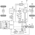
図1は、本発明の一実施例としてのハイブリッド自動車20の構成の概略を示す構成図である。実施例のハイブリッド自動車20は、図示するように、エンジン22と、プラネタリギヤ30と、モータMG1,MG2と、インバータ41,42と、バッテリ50と、外部給電装置60と、ハイブリッド用電子制御ユニット(以下、「HVECU」という)70と、を備える。
FIG. 1 is a configuration diagram showing an outline of the configuration of a
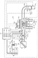
エンジン22は、ガソリンや軽油などを燃料として動力を出力する内燃機関として構成されている。このエンジン22は、エンジン用電子制御ユニット(以下、「エンジンECU」という)24によって運転制御されている。エンジン22は、図2に示すように、エアクリーナ122により清浄された空気をスロットルバルブ124を介して吸気管125に吸入すると共に燃料噴射弁126からガソリンを噴射して吸入された空気とガソリンとを混合する。そして、この混合気を吸気バルブ128を介して燃焼室に吸入し、点火プラグ130による電気火花によって爆発燃焼させて、そのエネルギにより押し下げられるピストン132の往復運動をクランクシャフト26の回転運動に変換する。エンジン22からの排気は、一酸化炭素(CO)や炭化水素(HC),窒素酸化物(NOx)の有害成分を浄化する浄化触媒(三元触媒)134aを有する浄化装置134を介して外気へ排出される。また、エンジン22の吸気管125には、燃料タンク160内で発生した蒸発燃料が蒸発燃料パージシステム170を介して供給(パージ)される。蒸発燃料パージシステム170は、燃料タンク160からの蒸発燃料を吸着する例えば活性炭などの吸着剤が充填され大気導入口172が設けられたキャニスタ174と、燃料タンク160とキャニスタ174とを連通する連通路175と、キャニスタ174と吸気管125とを連通するパージ通路176と、このパージ通路176に配置されたパージ制御バルブ178とを備える。蒸発燃料パージシステム170は、パージ制御バルブ178の開度を調節することにより流量を調整すると共に吸気管125内の吸気負圧を利用してキャニスタ174からの蒸発燃料を吸気管125にパージする。エンジン22は、こうして空気と蒸発燃料を含む燃料との混合気を燃焼室に吸引することができるようになっている。
The
エンジン22は、エンジン用電子制御ユニット(以下、エンジンECUという)24により制御されている。エンジンECU24は、CPU24aを中心とするマイクロプロセッサとして構成されており、CPU24aの他に処理プログラムを記憶するROM24bと、データを一時的に記憶するRAM24cと、図示しない入出力ポートおよび通信ポートとを備える。エンジンECU24には、エンジン22の状態を検出する種々のセンサからの信号が入力ポートを介して入力されている。入力ポートを介して入力される信号としては以下のものを挙げることができる。クランクシャフト26の回転位置を検出するクランクポジションセンサ140からのクランクポジション。エンジン22の冷却水の温度を検出する水温センサ142からの冷却水温Tw。燃焼室内に取り付けられた図示しない圧力センサからの筒内圧力。燃焼室へ吸排気を行なう吸気バルブ128や排気バルブを開閉するカムシャフトの回転位置を検出するカムポジションセンサ144からのカムポジション。スロットルバルブ124のポジションを検出するスロットルバルブポジションセンサ146からのスロットルポジション。吸気管125に取り付けられたエアフローメータ148からの吸入空気量Qa。同じく吸気管125に取り付けられた温度センサ149からの吸気温。浄化触媒134aの温度を検出する温度センサ134bからの触媒温度Tc。空燃比センサ135aからの空燃比AF。酸素センサ135bからの酸素信号。また、エンジンECU24からは、エンジン22を駆動するための種々の制御信号が出力ポートを介して出力されている。出力ポートを介して出力される制御信号としては以下のものを挙げることができる。燃料噴射弁126への駆動信号。スロットルバルブ124のポジションを調節するスロットルモータ136への駆動信号。イグナイタと一体化されたイグニッションコイル138への制御信号。吸気バルブ128の開閉タイミングを変更可能な可変バルブタイミング機構150への制御信号。燃料ポンプ162への駆動信号。パージ制御バルブ178への制御信号。エンジンECU24は、ハイブリッド用電子制御ユニット70と通信しており、ハイブリッド用電子制御ユニット70からの制御信号によりエンジン22を運転制御すると共に必要に応じてエンジン22の運転状態に関するデータを出力する。なお、エンジンECU24は、クランクポジションセンサ140からのクランクポジションに基づいてクランクシャフト26の回転数、即ちエンジン22の回転数Neも演算している。
The
プラネタリギヤ30は、シングルピニオン式の遊星歯車機構として構成されている。プラネタリギヤ30のサンギヤには、モータMG1の回転子が接続されている。プラネタリギヤ30のリングギヤには、駆動輪38a,38bにデファレンシャルギヤ37を介して連結された駆動軸36とモータMG2の回転子とが接続されている。プラネタリギヤ30のキャリヤには、エンジン22のクランクシャフト26が接続されている。
The
モータMG1は、例えば同期発電電動機として構成されている。このモータMG1は、上述したように、回転子がプラネタリギヤ30のサンギヤに接続されている。モータMG2は、例えば同期発電電動機として構成されている。このモータMG2は、上述したように、回転子が駆動軸36に接続されている。インバータ41,42は、バッテリ50と共に電力ライン54に接続されている。モータMG1,MG2は、モータ用電子制御ユニット(以下、「モータECU」という)40によって、インバータ41,42の図示しない複数のスイッチング素子がスイッチング制御されることにより、回転駆動される。
The motor MG1 is configured as a synchronous generator motor, for example. As described above, the motor MG1 has a rotor connected to the sun gear of the
モータECU40は、図示しないが、CPUを中心とするマイクロプロセッサとして構成されており、CPUの他に、処理プログラムを記憶するROMやデータを一時的に記憶するRAM,入出力ポート,通信ポートを備える。モータECU40には、モータMG1,MG2を駆動制御するのに必要な各種センサからの信号が入力ポートを介して入力されている。各種センサからの信号としては、以下のものを挙げることができる。モータMG1,MG2の回転子の回転位置を検出する回転位置検出センサ43,44からの回転位置θm1,θm2。モータMG1,MG2の各相に流れる電流を検出する電流センサからの相電流。モータECU40からは、インバータ41,42の図示しないスイッチング素子へのスイッチング制御信号などが出力ポートを介して出力されている。モータECU40は、HVECU70と通信ポートを介して接続されている。このモータECU40は、HVECU70からの制御信号によってモータMG1,MG2を駆動制御する。また、モータECU40は、必要に応じてモータMG1,MG2の駆動状態に関するデータをHVECU70に出力する。モータECU40は、回転位置検出センサ43,44からのモータMG1,MG2の回転子の回転位置θm1,θm2に基づいてモータMG1,MG2の回転数Nm1,Nm2を演算している。
Although not shown, the
バッテリ50は、例えばリチウムイオン二次電池として構成されており、上述したように、インバータ41,42と共に電力ライン54に接続されている。バッテリ50は、バッテリ用電子制御ユニット(以下、「バッテリECU」という)52によって管理されている。
The
バッテリECU52は、図示しないが、CPUを中心とするマイクロプロセッサとして構成されており、CPUの他に、処理プログラムを記憶するROMやデータを一時的に記憶するRAM,入出力ポート,通信ポートを備える。バッテリECU52には、バッテリ50を管理するのに必要な各種センサからの信号が入力ポートを介して入力されている。各種センサからの信号としては、以下のものを挙げることができる。バッテリ50の端子間に設置された電圧センサ51aからの電池電圧Vb。バッテリ50の出力端子に取り付けられた電流センサ51bからの電池電流Ib(バッテリ50から放電するときが正の値)。バッテリ50に取り付けられた温度センサ51cからの電池温度Tb。バッテリECU52は、HVECU70と通信ポートを介して接続されている。このバッテリECU52は、必要に応じてバッテリ50の状態に関するデータをHVECU70に出力する。バッテリECU52は、電流センサ51bからの電池電流Ibの積算値に基づいて蓄電割合SOCを演算している。蓄電割合SOCは、バッテリ50の全容量に対するバッテリ50から放電可能な電力の容量の割合である。また、バッテリECU52は、演算した蓄電割合SOCと、温度センサ51cからの電池温度Tbと、に基づいて入出力制限Win,Woutを演算している。入出力制限Win,Woutは、バッテリ50を充放電してもよい最大許容電力である。
Although not shown, the
外部給電装置60は、電力ライン54と、車両の構成要素でない外部機器の接続用のコンセント64と、に接続されている。この外部給電装置60は、図示しないが、インバータを有する。インバータは、電力ライン54の直流電力を所望の電圧の交流電力(例えば、AC100Vの電力)に変換して、コンセント64に接続された外部機器に供給する。以下、電力ライン54の電力を外部機器に供給することを「外部給電」という。このインバータは、HVECU70によって、図示しない複数のスイッチング素子がスイッチング制御される。
The external
HVECU70は、図示しないが、CPUを中心とするマイクロプロセッサとして構成されており、CPUの他に、処理プログラムを記憶するROMやデータを一時的に記憶するRAM,入出力ポート,通信ポートを備える。HVECU70には、各種センサからの信号が入力ポートを介して入力されている。各種センサからの信号としては、以下のものを挙げることができる。外部給電装置60による外部給電の給電電力を検出する電力センサ62からの給電電力Ph。イグニッションスイッチ80からのイグニッション信号。シフトレバー81の操作位置を検出するシフトポジションセンサ82からのシフトポジションSP。アクセルペダル83の踏み込み量を検出するアクセルペダルポジションセンサ84からのアクセル開度Acc。ブレーキペダル85の踏み込み量を検出するブレーキペダルポジションセンサ86からのブレーキペダルポジションBP。車速センサ88からの車速V。HVECU70からは、外部給電装置60のインバータのスイッチング素子へのスイッチング制御信号などが出力ポートを介して出力されている。HVECU70は、上述したように、エンジンECU24やモータECU40,バッテリECU52と通信ポートを介して接続されている。このHVECU70は、エンジンECU24やモータECU40,バッテリECU52と各種制御信号やデータのやりとりを行なっている。
Although not shown, the
なお、実施例のハイブリッド自動車20では、シフトポジションセンサ82により検出されるシフトポジションSPとしては、駐車時に用いる駐車ポジション(Pポジション),後進走行用のリバースポジション(Rポジション),中立のニュートラルポジション(Nポジション),前進走行用のドライブポジション(Dポジション)などがある。そして、シフトポジションSPがPポジションのときには、図示しないパーキングロック機構によって駆動輪38a,38bがロックされる。
In the
こうして構成された実施例のハイブリッド自動車20では、アクセル開度Accと車速Vとに基づいて駆動軸36の要求駆動力を設定し、要求駆動力に見合う要求動力が駆動軸36に出力されるように、エンジン22とモータMG1,MG2とを運転制御する。エンジン22とモータMG1,MG2の運転モードとしては、以下の(1)〜(3)のモードがある。
(1)トルク変換運転モード:要求動力に対応する動力がエンジン22から出力されるようにエンジン22を運転制御すると共に、エンジン22から出力される動力の全てが、プラネタリギヤ30とモータMG1,MG2とによってトルク変換されて、要求動力が駆動軸36に出力されるようにモータMG1,MG2を駆動制御するモード。
(2)充放電運転モード:要求動力とバッテリ50の充放電必要な電力との和に見合う動力がエンジン22から出力されるようにエンジン22を運転制御すると共に、エンジン22から出力される動力の全てまたは一部が、バッテリ50の充放電を伴ってプラネタリギヤ30とモータMG1,MG2とによってトルク変換されて、要求動力が駆動軸36に出力されるようにモータMG1,MG2を駆動制御するモード。
(3)モータ運転モード:エンジン22の運転を停止して、要求動力が駆動軸36に出力されるようにモータMG2を駆動制御するモード。
In the
(1) Torque conversion operation mode: The
(2) Charging / discharging operation mode: The
(3) Motor operation mode: Mode in which the operation of the
また、実施例のハイブリッド自動車20では、シフトポジションSPがPポジションのときには、基本的には、エンジン22を運転停止する。そして、図示しない補機(空調装置など)による電力消費,外部給電装置60による外部給電などによって、バッテリ50の蓄電割合SOCが予め定められた閾値Sst以下に至ると、モータMG1によってエンジン22をクランキングして始動する。そして、エンジン22からの動力を用いたモータMG1の発電によってバッテリ50が充電されるようにエンジン22とモータMG1とを制御する。以下、この制御を「所定充電制御」という。そして、バッテリ50の蓄電割合SOCが閾値Sstより大きい閾値Ssp以上に至ると、所定充電制御を終了し、エンジン22を運転停止する。
Further, in the
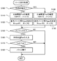
次に、こうして構成された実施例のハイブリッド自動車20の動作、特にキャニスタパージを行なう際の動作について説明する。図3は、キャニスタ174に蒸発燃料がある程度吸着されてキャニスタパージの実行が必要と判断されているときにエンジンECU24により実行されるパージ実行処理の一例を示すフローチャートである。この処理は、キャニスタパージが実行されるまで所定時間毎(例えば、数秒毎)に繰り返し実行される。
Next, the operation of the
パージ実行処理が実行されると、エンジンECU24は、まず、外部給電装置60により外部給電が行なわれているか否かを判定する(ステップS100)。この判定は、HVECU70により外部給電装置60による外部給電の制御を行なっているか否かの制御信号(例えばフラグ)を通信により受信し、受信した制御信号を調べることにより行なうことができる。
When the purge execution process is executed, the
外部給電装置60により外部給電が行なわれていないときには、キャニスタパージを許可するか否かの判定に用いる水温閾値Trefに予め定めた温度T1(例えば、35℃や40℃など)を設定すると共に(ステップS110)、最大パージ率Pmaxに予め定めた値P1(例えば、8%や10%など)を設定する(ステップS120)。ここで、パージ率は、吸入空気量に対する蒸発燃料ガス量(蒸発燃料ガス量/吸入空気量)である。最大パージ率Pmaxは、キャニスタパージを行なう際の許容されるパージ率の最大値である。そして、エンジン22が運転されているか否かを判定し(ステップS150)、エンジン22が運転されていないときには、キャニスタパージを実行することなく本処理を終了する。エンジン22が運転されているときには、水温センサ142からの冷却水温Twを入力し(ステップS160)、冷却水温Twが温度閾値Tref以上であるか否かを判定する(ステップS170)。冷却水温Twが温度閾値Tref未満のときには、キャニスタパージを実行することなく本処理を終了する。冷却水温Twが温度閾値Tref以上のときには、キャニスタパージを実行し(ステップS180)、本処理を終了する。キャニスタパージは、最大パージ率Pmaxの範囲内となるよう蒸発燃料パージシステム170のパージ制御バルブ178の開度を調節してキャニスタ174からの蒸発燃料を吸気管125にパージすることにより行なわれる。
When external power feeding is not performed by the external
一方、ステップS100で外部給電装置60により外部給電が行なわれていると判定されたときには、水温閾値Trefに外部給電が行なわれていないときの温度T1より低い温度T2(例えば、20℃や25℃など)を設定すると共に(ステップS130)、最大パージ率Pmaxに外部給電が行なわれていないときの値P1より大きな値P2(例えば、18%や20%など)を設定する(ステップS140)。そして、温度T2の温度閾値Trefと値P2の最大パージ率Pmaxを用いて、ステップS150〜S180の処理を実行する。即ち、エンジン22が運転されていなかったり、冷却水温Twが温度閾値Tref未満のときにはキャニスタパージを実行せず、エンジン22が運転されており、且つ、冷却水温Twが温度閾値Tref以上に至ったときにキャニスタパージを実行する。このように、外部給電装置60により外部給電が行なわれているときには、外部給電が行なわれていないときに比して、冷却水温Twが温度T1より低い温度T2以上でキャニスタパージを実行することにより、冷却水温Twが温度T1未満でもキャニスタパージを実行することができる。これにより、キャニスタパージを実行する機会を多くすることができる。また、この場合のキャニスタパージは、値P1より大きな値P2が設定された最大パージ率Pmaxの範囲内で行なわれるから、迅速にキャニスタパージを完了することができる。なお、外部給電が行なわれているときに冷却水温Twが低い温度T2以上で大きな値Pの最大パージ率Pmaxを用いてキャニスタパージを行なうことができるのは、外部給電中は停車していることに基づく。即ち、停車中は、キャニスタパージによりエンジン22の回転数が変動してもドライバビリティへの影響は小さいと考えることができるからである。
On the other hand, when it is determined in step S100 that the external power feeding is performed by the external
以上説明した実施例のハイブリッド自動車20では、外部給電装置60により外部給電が行なわれていないときには、エンジン22が運転されており、冷却水温Twが温度閾値Trefに設定された温度T1以上のときにキャニスタパージを実行する。一方、外部給電装置60により外部給電が行なわれているときには、エンジン22が運転されており、冷却水温Twが温度閾値Trefに設定された温度T2(T2<T1)以上のときにキャニスタパージを実行する。即ち、外部給電装置60により外部給電が行なわれているときには、外部給電が行なわれていないときに比して、冷却水温Twが温度T1より低い温度T2以上でキャニスタパージを実行する。これにより、キャニスタパージを行なう機会を多くすることができ、エボパエミッション性能を向上させることができる。また、外部給電の終了後にキャニスタパージのためにエンジン22の運転時間が長くなるのを抑制することができる。
In the
また、実施例のハイブリッド自動車20では、外部給電装置60により外部給電が行なわれていないときには、値P1が設定された最大パージ率Pmaxの範囲内でキャニスタパージを実行する。一方、外部給電装置60により外部給電が行なわれているときには、値P1より大きな値P2が設定された最大パージ率Pmaxの範囲内でキャニスタパージを実行する。このため、外部給電装置60により外部給電が行なわれているときには、外部給電が行なわれていないときに比して、迅速にキャニスタパージを完了することができる。
Further, in the
実施例のハイブリッド自動車20では、外部給電装置60により外部給電が行なわれているときには、外部給電が行なわれていないときに比して、大きな値P2の最大パージ率Pmaxを用いてキャニスタパージを実行するものとした。しかし、外部給電装置60により外部給電が行なわれているときでも、外部給電が行なわれていないときに用いる値P1の最大パージ率Pmaxを用いてキャニスタパージを実行するものとしてもよい。
In the
実施例のハイブリッド自動車20では、モータMG2からの動力を、駆動輪38a,38bに連結された駆動軸36に出力するものとした。しかし、図4の変形例のハイブリッド自動車120に例示するように、モータMG2からの動力を、駆動輪38a,38bに接続された車軸とは異なる車軸(図4における車輪39a,39bに接続された車軸)に出力するものとしてもよい。
In the
実施例のハイブリッド自動車20では、駆動輪38a,38bに連結された駆動軸36にプラネタリギヤ30を介してエンジン22およびモータMG1を接続すると共に駆動軸36にモータMG2を接続する構成とした。しかし、図5の変形例のハイブリッド自動車220に例示するように、駆動輪38a,38bに連結された駆動軸36に変速機230を介してモータMGを接続すると共にモータMGの回転軸にクラッチ229を介してエンジン22を接続する構成としてもよい。このハイブリッド自動車220では、外部給電装置60により外部給電を行なっている最中にエンジン22を始動してモータMGにより発電してバッテリ50を充電する際には、クラッチ229を係合すると共に変速機230を中立(ニュートラル)にすればよい。また、いわゆるシリーズハイブリッド自動車に本発明を適用するものとしてもよい。
In the
実施例の主要な要素と課題を解決するための手段の欄に記載した発明の主要な要素との対応関係について説明する。実施例では、エンジン22が「エンジン」に相当し、キャニスタ174が「キャニスタ」に相当し、パージ制御バルブ178が「パージバルブ」に相当し、エンジンECU24が「蒸発燃料用制御手段」に相当し、モータMG1が「発電機」に相当し、バッテリ50が「バッテリ」に相当し、外部給電装置60が「外部給電装置」に相当する。
The correspondence between the main elements of the embodiment and the main elements of the invention described in the column of means for solving the problems will be described. In the embodiment, the
なお、実施例の主要な要素と課題を解決するための手段の欄に記載した発明の主要な要素との対応関係は、実施例が課題を解決するための手段の欄に記載した発明を実施するための形態を具体的に説明するための一例であることから、課題を解決するための手段の欄に記載した発明の要素を限定するものではない。即ち、課題を解決するための手段の欄に記載した発明についての解釈はその欄の記載に基づいて行なわれるべきものであり、実施例は課題を解決するための手段の欄に記載した発明の具体的な一例に過ぎないものである。 The correspondence between the main elements of the embodiment and the main elements of the invention described in the column of means for solving the problem is the same as that of the embodiment described in the column of means for solving the problem. Therefore, the elements of the invention described in the column of means for solving the problems are not limited. That is, the interpretation of the invention described in the column of means for solving the problems should be made based on the description of the column, and the examples are those of the invention described in the column of means for solving the problems. It is only a specific example.
以上、本発明を実施するための形態について実施例を用いて説明したが、本発明はこうした実施例に何等限定されるものではなく、本発明の要旨を逸脱しない範囲内において、種々なる形態で実施し得ることは勿論である。 As mentioned above, although the form for implementing this invention was demonstrated using the Example, this invention is not limited at all to such an Example, In the range which does not deviate from the summary of this invention, it is with various forms. Of course, it can be implemented.
本発明は、ハイブリッド自動車の製造産業などに利用可能である。 The present invention can be used in the manufacturing industry of hybrid vehicles.
20,120,220 ハイブリッド自動車、22 エンジン、24 エンジン用電子制御ユニット(エンジンECU)、24a CPU、24b ROM、24c RAM、26 クランクシャフト、30 プラネタリギヤ、36 駆動軸、37 デファレンシャルギヤ、38a,38b 駆動輪、39a,39b 車輪、40 モータ用電子制御ユニット(モータECU)、41,42 インバータ、43,44 回転位置検出センサ、50 バッテリ、51a 電圧センサ、51b 電流センサ、51c 温度センサ、52 バッテリ用電子制御ユニット(バッテリECU)、54 電力ライン、60 外部給電装置、62 電力センサ、64 コンセント、70 ハイブリッド用電子制御ユニット(HVECU)、80 イグニッションスイッチ、81 シフトレバー、82 シフトポジションセンサ、83 アクセルペダル、84 アクセルペダルポジションセンサ、85 ブレーキペダル、86 ブレーキペダルポジションセンサ、88 車速センサ、122 エアクリーナ、124 スロットルバルブ、125 吸気管、126 燃料噴射弁、128 吸気バルブ、130 点火プラグ、132 ピストン、134 浄化装置、134a 浄化触媒、134b 温度センサ、135a 空燃比センサ、135b 酸素センサ、136 スロットルモータ、138 イグニッションコイル、140 クランクポジションセンサ、142 水温センサ、144 カムポジションセンサ、146 スロットルバルブポジションセンサ、148 エアフローメータ、149 温度センサ、150 可変バルブタイミング機構、160 燃料タンク、162 燃料ポンプ、170 蒸発燃料パージシステム、172 大気導入口、174 キャニスタ、175 連通路、176 パージ通路、178 パージ制御バルブ、MG,MG1,MG2 モータ、229 クラッチ、230 変速機。 20, 120, 220 Hybrid vehicle, 22 engine, 24 engine electronic control unit (engine ECU), 24a CPU, 24b ROM, 24c RAM, 26 crankshaft, 30 planetary gear, 36 drive shaft, 37 differential gear, 38a, 38b drive Wheel, 39a, 39b Wheel, 40 Motor electronic control unit (motor ECU), 41, 42 Inverter, 43, 44 Rotation position detection sensor, 50 battery, 51a Voltage sensor, 51b Current sensor, 51c Temperature sensor, 52 Battery electronics Control unit (battery ECU), 54 power line, 60 external power supply device, 62 power sensor, 64 outlet, 70 electronic control unit for hybrid (HVECU), 80 ignition switch, 81 Shift lever, 82 Shift position sensor, 83 Accelerator pedal, 84 Accelerator pedal position sensor, 85 Brake pedal, 86 Brake pedal position sensor, 88 Vehicle speed sensor, 122 Air cleaner, 124 Throttle valve, 125 Intake pipe, 126 Fuel injection valve, 128 Intake Valve, 130 Spark plug, 132 Piston, 134 Purification device, 134a Purification catalyst, 134b Temperature sensor, 135a Air-fuel ratio sensor, 135b Oxygen sensor, 136 Throttle motor, 138 Ignition coil, 140 Crank position sensor, 142 Water temperature sensor, 144 Cam position Sensor, 146 Throttle valve position sensor, 148 Air flow meter, 149 Temperature sensor, 150 Variable valve timing Mechanism, 160 fuel tank, 162 fuel pump, 170 evaporative fuel purge system, 172 air inlet, 174 canister, 175 communication path, 176 purge path, 178 purge control valve, MG, MG1, MG2 motor, 229 clutch, 230 speed change Machine.
Claims (3)
前記燃料タンク内で発生した蒸発燃料を吸着するキャニスタと、
前記キャニスタで吸着した蒸発燃料を含む蒸発燃料ガスを前記エンジンの吸気管へ供給する供給管に取り付けられたパージバルブと、
前記蒸発燃料ガスが前記吸気管へ供給されるよう前記パージバルブを開閉制御する蒸発燃料用制御手段と、
前記エンジンからの動力を用いて発電する発電機と、
前記発電機に電力ラインを介して接続されたバッテリと、
前記電力ラインの電力を外部機器に供給する外部給電を行なう外部給電装置と、
を備えるハイブリッド自動車であって、
前記蒸発燃料用制御手段は、前記外部給電装置により外部給電しているときには、前記外部給電装置により外部給電していないときに比して、前記蒸発燃料ガスの前記吸気管へ供給されやすくなる実行条件を用いて前記パージバルブを開閉制御する手段である、
ことを特徴とするハイブリッド自動車。 An engine that outputs power by receiving supply of fuel stored in a fuel tank;
A canister that adsorbs the evaporated fuel generated in the fuel tank;
A purge valve attached to a supply pipe for supplying evaporated fuel gas containing evaporated fuel adsorbed by the canister to the intake pipe of the engine;
Evaporative fuel control means for opening and closing the purge valve so that the evaporative fuel gas is supplied to the intake pipe;
A generator that generates power using power from the engine;
A battery connected to the generator via a power line;
An external power supply device for performing external power supply for supplying power from the power line to an external device;
A hybrid vehicle comprising:
The evaporative fuel control means is more likely to supply the evaporative fuel gas to the intake pipe when external power is supplied from the external power supply device than when external power is not supplied from the external power supply device. Means for controlling the opening and closing of the purge valve using conditions,
A hybrid vehicle characterized by that.
前記実行条件は、前記外部給電装置により外部給電していないときには前記エンジンの冷却水の温度が第1温度以上である条件であり、前記外部給電装置により外部給電しているときには前記エンジンの冷却水の温度が前記第1温度より低い第2温度以上である条件である、
ハイブリッド自動車。 The hybrid vehicle according to claim 1,
The execution condition is a condition in which the temperature of the cooling water of the engine is equal to or higher than a first temperature when external power is not supplied by the external power supply device, and the cooling water of the engine is externally supplied by the external power supply device. Is a condition that the temperature is equal to or higher than a second temperature lower than the first temperature,
Hybrid car.
前記実行条件は、前記外部給電装置により外部給電していないときには第1パージ率を最大パージ率とする条件であり、前記外部給電装置により外部給電しているときには前記第1パージ率より高い第2パージ率を前記最大パージ率とする条件である、
ハイブリッド自動車。 A hybrid vehicle according to claim 1 or 2,
The execution condition is a condition in which the first purge rate is set to the maximum purge rate when external power is not supplied from the external power supply device, and the second purge rate is higher than the first purge rate when external power is supplied from the external power supply device. The purge rate is a condition for setting the maximum purge rate.
Hybrid car.
Priority Applications (4)
| Application Number | Priority Date | Filing Date | Title |
|---|---|---|---|
| JP2015066893A JP6160645B2 (en) | 2015-03-27 | 2015-03-27 | Hybrid car |
| DE102016105535.2A DE102016105535B4 (en) | 2015-03-27 | 2016-03-24 | hybrid vehicle |
| US15/080,898 US10408167B2 (en) | 2015-03-27 | 2016-03-25 | Hybrid vehicle |
| CN201610177280.2A CN106014700B (en) | 2015-03-27 | 2016-03-25 | Hybrid vehicle |
Applications Claiming Priority (1)
| Application Number | Priority Date | Filing Date | Title |
|---|---|---|---|
| JP2015066893A JP6160645B2 (en) | 2015-03-27 | 2015-03-27 | Hybrid car |
Publications (2)
| Publication Number | Publication Date |
|---|---|
| JP2016185766A JP2016185766A (en) | 2016-10-27 |
| JP6160645B2 true JP6160645B2 (en) | 2017-07-12 |
Family
ID=56890343
Family Applications (1)
| Application Number | Title | Priority Date | Filing Date |
|---|---|---|---|
| JP2015066893A Expired - Fee Related JP6160645B2 (en) | 2015-03-27 | 2015-03-27 | Hybrid car |
Country Status (4)
| Country | Link |
|---|---|
| US (1) | US10408167B2 (en) |
| JP (1) | JP6160645B2 (en) |
| CN (1) | CN106014700B (en) |
| DE (1) | DE102016105535B4 (en) |
Families Citing this family (2)
| Publication number | Priority date | Publication date | Assignee | Title |
|---|---|---|---|---|
| CA3182744A1 (en) * | 2015-06-12 | 2016-12-15 | Bae Systems Controls Inc. | Method and system for reducing emissions from an internal combustion engine |
| JP2019189178A (en) * | 2018-04-27 | 2019-10-31 | トヨタ自動車株式会社 | Control device for hybrid vehicle |
Family Cites Families (27)
| Publication number | Priority date | Publication date | Assignee | Title |
|---|---|---|---|---|
| JP2551222B2 (en) * | 1990-10-15 | 1996-11-06 | トヨタ自動車株式会社 | Failure diagnosis device for evaporation purge system |
| JP3286492B2 (en) | 1995-04-28 | 2002-05-27 | 本田技研工業株式会社 | Control device for on-board power generator |
| JP3257402B2 (en) | 1996-06-14 | 2002-02-18 | 日産自動車株式会社 | Control device for engine for driving generator of hybrid electric vehicle |
| JP4093678B2 (en) * | 1999-05-11 | 2008-06-04 | 三菱電機株式会社 | Electric motor control device |
| US6622804B2 (en) * | 2001-01-19 | 2003-09-23 | Transportation Techniques, Llc. | Hybrid electric vehicle and method of selectively operating the hybrid electric vehicle |
| JP3891852B2 (en) * | 2002-01-31 | 2007-03-14 | 株式会社日本自動車部品総合研究所 | Fuel vapor processing apparatus for internal combustion engine |
| WO2006030528A1 (en) * | 2004-09-17 | 2006-03-23 | Toyota Jidosha Kabushiki Kaisha | Automobile and method of controlling internal combustion engine |
| JP2006158123A (en) * | 2004-11-30 | 2006-06-15 | Toyota Motor Corp | Ac voltage output device and vehicle equipped therewith |
| US7464698B2 (en) * | 2006-04-26 | 2008-12-16 | Denso Corporation | Air-fuel ratio control apparatus of internal combustion engine |
| JP4743082B2 (en) * | 2006-11-01 | 2011-08-10 | トヨタ自動車株式会社 | Power supply system and vehicle equipped with the same |
| JP2008151064A (en) * | 2006-12-19 | 2008-07-03 | Toyota Motor Corp | Control device for internal combustion engine |
| JP4208016B2 (en) * | 2007-02-13 | 2009-01-14 | トヨタ自動車株式会社 | HYBRID VEHICLE, HYBRID VEHICLE CONTROL METHOD, HYBRID VEHICLE CONTROL PROGRAM, AND RECORDING MEDIUM CONTAINING THE PROGRAM |
| JP4270305B2 (en) * | 2007-05-30 | 2009-05-27 | トヨタ自動車株式会社 | Hybrid vehicle |
| JP2009085036A (en) * | 2007-09-27 | 2009-04-23 | Toyota Motor Corp | Evaporated fuel processing device |
| JP4702407B2 (en) * | 2008-07-02 | 2011-06-15 | マツダ株式会社 | Method and apparatus for controlling dual fuel engine |
| US8237305B2 (en) * | 2008-07-22 | 2012-08-07 | Alexander Kade | Auxiliary electrical power system for vehicular fuel economy improvement |
| JP5185059B2 (en) * | 2008-10-17 | 2013-04-17 | トヨタ自動車株式会社 | Control device for hybrid vehicle |
| JP5348549B2 (en) * | 2009-08-04 | 2013-11-20 | スズキ株式会社 | Electric vehicle |
| RU2505905C2 (en) * | 2009-12-21 | 2014-01-27 | Тойота Дзидося Кабусики Кайся | Charging system |
| JP5278613B2 (en) * | 2010-06-24 | 2013-09-04 | トヨタ自動車株式会社 | Control device for internal combustion engine, hybrid vehicle including the same, and control method for internal combustion engine |
| JP2013002287A (en) * | 2011-06-13 | 2013-01-07 | Aisan Industry Co Ltd | Evaporated fuel treatment apparatus |
| JP5704338B2 (en) * | 2011-07-07 | 2015-04-22 | 三菱自動車工業株式会社 | Fuel evaporative emission control device for internal combustion engine |
| JP5790466B2 (en) * | 2011-12-08 | 2015-10-07 | トヨタ自動車株式会社 | Control device for hybrid vehicle |
| JP2013184621A (en) * | 2012-03-09 | 2013-09-19 | Nissan Motor Co Ltd | Evaporation fuel processing apparatus of hybrid vehicle |
| JP5888033B2 (en) * | 2012-03-16 | 2016-03-16 | トヨタ自動車株式会社 | Control device for hybrid vehicle |
| JP5831501B2 (en) * | 2013-06-05 | 2015-12-09 | トヨタ自動車株式会社 | Internal combustion engine |
| JP6040962B2 (en) * | 2014-06-03 | 2016-12-07 | 株式会社デンソー | Evaporative fuel processing equipment |
-
2015
- 2015-03-27 JP JP2015066893A patent/JP6160645B2/en not_active Expired - Fee Related
-
2016
- 2016-03-24 DE DE102016105535.2A patent/DE102016105535B4/en not_active Expired - Fee Related
- 2016-03-25 US US15/080,898 patent/US10408167B2/en not_active Expired - Fee Related
- 2016-03-25 CN CN201610177280.2A patent/CN106014700B/en not_active Expired - Fee Related
Also Published As
| Publication number | Publication date |
|---|---|
| DE102016105535A1 (en) | 2016-09-29 |
| US10408167B2 (en) | 2019-09-10 |
| CN106014700B (en) | 2018-11-09 |
| DE102016105535B4 (en) | 2019-01-24 |
| JP2016185766A (en) | 2016-10-27 |
| US20160280202A1 (en) | 2016-09-29 |
| CN106014700A (en) | 2016-10-12 |
Similar Documents
| Publication | Publication Date | Title |
|---|---|---|
| JP2018083570A (en) | Hybrid automobile | |
| JP6248997B2 (en) | Hybrid car | |
| JP6686859B2 (en) | Hybrid car | |
| JP2014073693A (en) | Hybrid vehicle | |
| JP2018062199A (en) | Hybrid vehicle | |
| JP2013193533A (en) | Hybrid vehicle | |
| CN109747623B (en) | Hybrid electric vehicle | |
| JP5904131B2 (en) | Hybrid vehicle control device and hybrid vehicle | |
| JP2018154142A (en) | Hybrid vehicle | |
| JP6160645B2 (en) | Hybrid car | |
| JP2010083319A (en) | Hybrid vehicle and method for controlling the same | |
| JP2010105626A (en) | Vehicle and control method therefor | |
| JP5246090B2 (en) | Hybrid vehicle and control method thereof | |
| JP2014189081A (en) | Hybrid vehicle | |
| JP2018105197A (en) | Internal combustion engine device | |
| JP2014091366A (en) | Hybrid automobile | |
| JP2017128212A (en) | Hybrid vehicle | |
| JP2016120853A (en) | Control device of hybrid automobile | |
| JP2016159878A (en) | Control device of hybrid vehicle | |
| JP6277972B2 (en) | Hybrid car | |
| JP6020276B2 (en) | Hybrid car | |
| JP2020001487A (en) | Hybrid vehicle | |
| JP5796440B2 (en) | Idling learning device for hybrid vehicles | |
| JP2013067297A (en) | Hybrid vehicle | |
| JP5040833B2 (en) | Hybrid vehicle and control method thereof |
Legal Events
| Date | Code | Title | Description |
|---|---|---|---|
| TRDD | Decision of grant or rejection written | ||
| A01 | Written decision to grant a patent or to grant a registration (utility model) |
Free format text: JAPANESE INTERMEDIATE CODE: A01 Effective date: 20170516 |
|
| A61 | First payment of annual fees (during grant procedure) |
Free format text: JAPANESE INTERMEDIATE CODE: A61 Effective date: 20170529 |
|
| R151 | Written notification of patent or utility model registration |
Ref document number: 6160645 Country of ref document: JP Free format text: JAPANESE INTERMEDIATE CODE: R151 |
|
| LAPS | Cancellation because of no payment of annual fees |