JP5246090B2 - Hybrid vehicle and control method thereof - Google Patents
Hybrid vehicle and control method thereof Download PDFInfo
- Publication number
- JP5246090B2 JP5246090B2 JP2009177936A JP2009177936A JP5246090B2 JP 5246090 B2 JP5246090 B2 JP 5246090B2 JP 2009177936 A JP2009177936 A JP 2009177936A JP 2009177936 A JP2009177936 A JP 2009177936A JP 5246090 B2 JP5246090 B2 JP 5246090B2
- Authority
- JP
- Japan
- Prior art keywords
- power
- braking
- temperature
- motor
- internal combustion
- Prior art date
- Legal status (The legal status is an assumption and is not a legal conclusion. Google has not performed a legal analysis and makes no representation as to the accuracy of the status listed.)
- Expired - Fee Related
Links
- 238000000034 method Methods 0.000 title claims description 13
- 239000003054 catalyst Substances 0.000 claims description 75
- 238000000746 purification Methods 0.000 claims description 60
- 238000002485 combustion reaction Methods 0.000 claims description 57
- 239000000446 fuel Substances 0.000 claims description 44
- 238000002347 injection Methods 0.000 claims description 32
- 239000007924 injection Substances 0.000 claims description 32
- 238000003860 storage Methods 0.000 claims description 6
- 230000001172 regenerating effect Effects 0.000 claims description 3
- 230000007246 mechanism Effects 0.000 description 28
- 238000009826 distribution Methods 0.000 description 18
- 230000010354 integration Effects 0.000 description 17
- 230000009467 reduction Effects 0.000 description 9
- 238000010586 diagram Methods 0.000 description 8
- 238000004891 communication Methods 0.000 description 7
- 230000006866 deterioration Effects 0.000 description 7
- MWUXSHHQAYIFBG-UHFFFAOYSA-N nitrogen oxide Inorganic materials O=[N] MWUXSHHQAYIFBG-UHFFFAOYSA-N 0.000 description 5
- 238000012937 correction Methods 0.000 description 4
- 230000007423 decrease Effects 0.000 description 4
- 238000001514 detection method Methods 0.000 description 4
- 229930195733 hydrocarbon Natural products 0.000 description 4
- 150000002430 hydrocarbons Chemical class 0.000 description 4
- QVGXLLKOCUKJST-UHFFFAOYSA-N atomic oxygen Chemical group [O] QVGXLLKOCUKJST-UHFFFAOYSA-N 0.000 description 3
- 230000008859 change Effects 0.000 description 3
- 238000007599 discharging Methods 0.000 description 3
- 239000007789 gas Substances 0.000 description 3
- 239000001301 oxygen Substances 0.000 description 3
- 229910052760 oxygen Inorganic materials 0.000 description 3
- 230000008569 process Effects 0.000 description 3
- XLYOFNOQVPJJNP-UHFFFAOYSA-N water Substances O XLYOFNOQVPJJNP-UHFFFAOYSA-N 0.000 description 3
- 239000004215 Carbon black (E152) Substances 0.000 description 2
- UGFAIRIUMAVXCW-UHFFFAOYSA-N Carbon monoxide Chemical compound [O+]#[C-] UGFAIRIUMAVXCW-UHFFFAOYSA-N 0.000 description 2
- 229910002091 carbon monoxide Inorganic materials 0.000 description 2
- 238000006243 chemical reaction Methods 0.000 description 2
- 230000001360 synchronised effect Effects 0.000 description 2
- 230000005540 biological transmission Effects 0.000 description 1
- 239000003990 capacitor Substances 0.000 description 1
- 239000002826 coolant Substances 0.000 description 1
- 238000001816 cooling Methods 0.000 description 1
- 239000000498 cooling water Substances 0.000 description 1
- 230000000994 depressogenic effect Effects 0.000 description 1
- 230000009699 differential effect Effects 0.000 description 1
- 238000010892 electric spark Methods 0.000 description 1
- 230000005611 electricity Effects 0.000 description 1
- 238000002474 experimental method Methods 0.000 description 1
- 230000006698 induction Effects 0.000 description 1
- 238000004519 manufacturing process Methods 0.000 description 1
- 239000000203 mixture Substances 0.000 description 1
- 230000004048 modification Effects 0.000 description 1
- 238000012986 modification Methods 0.000 description 1
- 230000007935 neutral effect Effects 0.000 description 1
- 238000010248 power generation Methods 0.000 description 1
- 238000012545 processing Methods 0.000 description 1
- 230000004044 response Effects 0.000 description 1
- 230000006641 stabilisation Effects 0.000 description 1
- 238000011105 stabilization Methods 0.000 description 1
Images


Classifications
-
- Y—GENERAL TAGGING OF NEW TECHNOLOGICAL DEVELOPMENTS; GENERAL TAGGING OF CROSS-SECTIONAL TECHNOLOGIES SPANNING OVER SEVERAL SECTIONS OF THE IPC; TECHNICAL SUBJECTS COVERED BY FORMER USPC CROSS-REFERENCE ART COLLECTIONS [XRACs] AND DIGESTS
- Y02—TECHNOLOGIES OR APPLICATIONS FOR MITIGATION OR ADAPTATION AGAINST CLIMATE CHANGE
- Y02T—CLIMATE CHANGE MITIGATION TECHNOLOGIES RELATED TO TRANSPORTATION
- Y02T10/00—Road transport of goods or passengers
- Y02T10/60—Other road transportation technologies with climate change mitigation effect
- Y02T10/62—Hybrid vehicles
Landscapes
- Cooling, Air Intake And Gas Exhaust, And Fuel Tank Arrangements In Propulsion Units (AREA)
- Hybrid Electric Vehicles (AREA)
- Control Of Vehicle Engines Or Engines For Specific Uses (AREA)
- Electric Propulsion And Braking For Vehicles (AREA)
Description
本発明は、ハイブリッド車およびその制御方法に関する。 The present invention relates to a hybrid vehicle and a control method thereof.
従来、この種のハイブリッド車としては、排気を浄化する浄化触媒を有する浄化装置が取り付けられたエンジンと、エンジンをクランキング可能な第1モータと、車軸に接続された駆動軸に動力を出力可能な第2モータと、エンジンの出力軸と第1モータの回転軸と駆動軸とに接続された3軸式のプラネタリギヤ機構と、第1モータおよび第2モータと電力をやりとりするバッテリとを備え、運転者の操作により1〜6速の仮想のシフトチェンジを可能とする仮想シフトポジション(シーケンシャルシフトポジション)により走行可能なものが提案されている(例えば、特許文献1参照)。このハイブリッド車では、シーケンシャルシフトポジションの選択時にアクセルオフに基づく減速要求がなされたときには、燃料カットした状態のエンジンを第1モータによってモータリングしてシフトポジションと車速とに応じた回転数で回転させることにより、いわゆるエンジンブレーキによる制動力を駆動軸に作用させている。 Conventionally, this type of hybrid vehicle can output power to an engine equipped with a purification device having a purification catalyst for purifying exhaust, a first motor capable of cranking the engine, and a drive shaft connected to the axle. A second motor, a three-axis planetary gear mechanism connected to the output shaft of the engine, the rotation shaft of the first motor, and the drive shaft, and a battery for exchanging power with the first motor and the second motor, There has been proposed a vehicle capable of traveling at a virtual shift position (sequential shift position) that enables a virtual shift change of 1 to 6 speeds by a driver's operation (see, for example, Patent Document 1). In this hybrid vehicle, when a deceleration request based on accelerator-off is made when a sequential shift position is selected, the engine in a fuel cut state is motored by the first motor to rotate at a rotational speed corresponding to the shift position and the vehicle speed. Thus, a braking force by so-called engine brake is applied to the drive shaft.
こうしたハイブリッド車では、浄化触媒の温度が低くその浄化触媒が活性化していない状態でのアクセルオフ時に、燃料噴射を停止した状態のエンジンを第1モータによってモータリングして制動力を駆動軸に作用させる制御を行なうと、その後に燃料噴射を再開する際に燃焼の安定化などの理由によってエンジンに供給する燃料の増量補正を行なったときに、エンジンの排気を十分に浄化できずにエミッションの悪化を招くおそれがある。 In such a hybrid vehicle, when the accelerator is turned off when the temperature of the purification catalyst is low and the purification catalyst is not activated, the engine in a state where the fuel injection is stopped is motored by the first motor to apply the braking force to the drive shaft. If the control is performed, when the fuel injection supplied to the engine is corrected for the reason of stabilization of combustion when restarting the fuel injection after that, the exhaust of the engine cannot be sufficiently purified and the emission deteriorates. May be incurred.
本発明のハイブリッド車およびその制御方法は、エミッションの悪化を抑制することを主目的とする。 The main purpose of the hybrid vehicle and the control method thereof according to the present invention is to suppress the deterioration of emissions.
本発明のハイブリッド車およびその制御方法は、上述の主目的を達成するために以下の手段を採った。 The hybrid vehicle of the present invention and its control method employ the following means in order to achieve the main object described above.
本発明のハイブリッド車は、
排気系に排気を浄化する浄化触媒を有する浄化装置が取り付けられた内燃機関と、
動力を入出力可能な発電機と、
車軸に連結された駆動軸と前記内燃機関の出力軸と前記発電機の回転軸との3軸に接続され、該3軸のうちのいずれか2軸に入出力される動力に基づいて残余の軸に動力を入出力する3軸式動力入出力手段と、
前記駆動軸に動力を入出力可能な電動機と、
前記発電機および前記電動機と電力のやりとりが可能な蓄電手段と、
通常の走行用ポジションに比してアクセルオフ時に大きな制動力が要求される制動用ポジションにシフトポジションがあってアクセルオフのとき、前記浄化触媒の温度が該浄化触媒が活性化する温度範囲の下限として定められた下限温度以上のときには前記内燃機関の燃料噴射の停止および前記発電機による前記内燃機関のモータリングを伴って車両に要求される要求制動力により走行するよう前記内燃機関と前記発電機と前記電動機とを制御するモータリング制動制御と前記内燃機関の燃料噴射を伴って前記要求制動力により走行するよう前記内燃機関と前記発電機と前記電動機とを制御する運転制動制御とのうち前記モータリング制動制御を優先して実行し、前記浄化触媒の温度が前記下限温度未満のときには前記モータリング制動制御と前記運転制動制御とのうち前記運転制動制御を優先して実行するアクセルオフ時制御手段と、
を備えることを要旨とする。
The hybrid vehicle of the present invention
An internal combustion engine having a purification device having a purification catalyst for purifying exhaust gas in an exhaust system;
A generator capable of inputting and outputting power;
It is connected to three shafts, that is, a drive shaft coupled to an axle, an output shaft of the internal combustion engine, and a rotating shaft of the generator, and the remaining power is determined based on power input / output to / from any two of the three shafts. 3-axis power input / output means for inputting / outputting power to the shaft;
An electric motor capable of inputting and outputting power to the drive shaft;
Power storage means capable of exchanging electric power with the generator and the motor;
The lower limit of the temperature range in which the temperature of the purification catalyst is activated when the shift position is at the braking position where a large braking force is required when the accelerator is off compared to the normal driving position and the accelerator is off. The internal combustion engine and the generator so that the vehicle travels with the required braking force required for the vehicle with stop of fuel injection of the internal combustion engine and motoring of the internal combustion engine by the generator Motoring braking control for controlling the motor and the motor, and driving braking control for controlling the internal combustion engine, the generator and the motor so as to travel with the required braking force with fuel injection of the internal combustion engine. Priority is given to motoring braking control, and the motoring braking control is performed when the temperature of the purification catalyst is lower than the lower limit temperature. An accelerator-off time control means for performing preferentially the operation braking control of said operating brake control,
It is a summary to provide.
この本発明のハイブリッド車では、通常の走行用ポジションに比してアクセルオフ時に大きな制動力が要求される制動用ポジションにシフトポジションがあってアクセルオフのときにおいて、浄化触媒の温度が浄化触媒が活性化する温度範囲の下限として定められた下限温度以上のときには、内燃機関の燃料噴射の停止および発電機による内燃機関のモータリングを伴って車両に要求される要求制動力により走行するよう内燃機関と発電機と電動機とを制御するモータリング制動制御と内燃機関の燃料噴射を伴って要求制動力により走行するよう内燃機関と発電機と電動機とを制御する運転制動制御とのうちモータリング制動制御を優先して実行する。これにより、いわゆるエンジンブレーキによる制動力を車両に作用させることができる。一方、通常の走行用ポジションに比してアクセルオフ時に大きな制動力が要求される制動用ポジションにシフトポジションがあってアクセルオフのときにおいて、浄化触媒の温度が下限温度未満のときには、モータリング制動制御と運転制動制御とのうち運転制動制御を優先して実行する。これにより、内燃機関の燃料噴射が停止されにくくなるから、浄化触媒が活性化していない状態で燃料噴射を停止してから再開する際に生じるおそれのあるエミッションの悪化を抑制することができる。ここで、「3軸式動力入出力手段」は、シングルピニオン式やダブルピニオン式の遊星歯車機構であるものとすることもできるし、デファレンシャルギヤであるものとすることもできる。 In the hybrid vehicle of the present invention, the temperature of the purifying catalyst is the temperature of the purifying catalyst when the shift position is at the braking position where a larger braking force is required when the accelerator is off than when the accelerator is off and the accelerator is off. When the temperature is equal to or higher than the lower limit temperature set as the lower limit of the temperature range to be activated, the internal combustion engine travels with the required braking force required for the vehicle with the stop of fuel injection of the internal combustion engine and motoring of the internal combustion engine by the generator Motoring braking control for controlling the internal combustion engine, the generator and the motor so as to travel with the required braking force accompanying the fuel injection of the internal combustion engine and the motoring braking control for controlling the motor, the generator and the motor Execute with priority. Thereby, the braking force by what is called an engine brake can be made to act on a vehicle. On the other hand, when there is a shift position at the braking position where a large braking force is required when the accelerator is off compared to the normal driving position and the accelerator is off and the temperature of the purification catalyst is lower than the lower limit temperature, motoring braking is performed. Of the control and the operation braking control, the operation braking control is preferentially executed. This makes it difficult to stop the fuel injection of the internal combustion engine, so that it is possible to suppress the deterioration of the emission that may occur when the fuel injection is stopped and restarted in a state where the purification catalyst is not activated. Here, the “three-axis power input / output means” may be a single pinion type or double pinion type planetary gear mechanism, or may be a differential gear.
こうした本発明のハイブリッド車において、前記アクセルオフ時制御手段は、前記シフトポジションが前記制動用ポジションにあってアクセルオフのとき、前記浄化触媒の温度が前記下限温度以上のときには前記要求制動力に応じた要求制動パワーが第1のパワー範囲内のときに前記自立運転制動制御を実行すると共に前記要求制動パワーが前記第1のパワー範囲外のときに前記モータリング制動制御を実行し、前記浄化触媒の温度が前記下限温度未満のときには前記要求制動パワーが前記第1のパワー範囲よりも広い第2のパワー範囲内のときに前記自立運転制動制御を実行すると共に前記要求制動パワーが前記第2のパワー範囲外のときに前記モータリング制動制御を実行する手段である、ものとすることもできる。この場合、前記第1のパワー範囲および前記第2のパワー範囲は、前記内燃機関のモータリングを伴わずに前記電動機の回生制動によって前記要求制動力により走行する範囲として定められるパワー範囲である、ものとすることもできる。 In such a hybrid vehicle of the present invention, the accelerator-off time control means responds to the required braking force when the shift position is at the braking position and the accelerator is off, and when the temperature of the purification catalyst is equal to or higher than the lower limit temperature. The self-sustained operation braking control is executed when the required braking power is within the first power range, and the motoring braking control is executed when the required braking power is outside the first power range. When the required temperature is less than the lower limit temperature, the self-sustained operation braking control is executed when the required braking power is within a second power range wider than the first power range, and the required braking power is It may be a means for executing the motoring braking control when out of a power range. In this case, the first power range and the second power range are power ranges that are determined as a range that travels by the required braking force by regenerative braking of the electric motor without motoring of the internal combustion engine. It can also be.
また、本発明のハイブリッド車において、前記アクセルオフ時制御手段は、前記シフトポジションが前記制動用ポジションにあってアクセルオフのときにおいて、前記浄化触媒の温度が前記下限温度未満のときには、前記浄化触媒の温度が前記下限温度以上のときに比して小さな制動力を前記要求制動力とする手段である、ものとすることもできる。 Further, in the hybrid vehicle of the present invention, the accelerator-off time control means is configured such that when the shift position is at the braking position and the accelerator is off, and the temperature of the purification catalyst is less than the lower limit temperature, the purification catalyst. It is also possible to make the required braking force a smaller braking force than when the temperature is equal to or higher than the lower limit temperature.
本発明のハイブリッド車の制御方法は、
排気系に排気を浄化する浄化触媒を有する浄化装置が取り付けられた内燃機関と、動力を入出力可能な発電機と、車軸に連結された駆動軸と前記内燃機関の出力軸と前記発電機の回転軸との3軸に接続され該3軸のうちのいずれか2軸に入出力される動力に基づいて残余の軸に動力を入出力する3軸式動力入出力手段と、前記駆動軸に動力を入出力可能な電動機と、前記発電機および前記電動機と電力のやりとりが可能な蓄電手段と、を備えるハイブリッド車の制御方法であって、
通常の走行用ポジションに比してアクセルオフ時に大きな制動力が要求される制動用ポジションにシフトポジションがあってアクセルオフのとき、前記浄化触媒の温度が該浄化触媒が活性化する温度範囲の下限として定められた下限温度以上のときには前記内燃機関の燃料噴射の停止および前記発電機による前記内燃機関のモータリングを伴って車両に要求される要求制動力により走行するよう前記内燃機関と前記発電機と前記電動機とを制御するモータリング制動制御と前記内燃機関の燃料噴射を伴って前記要求制動力により走行するよう前記内燃機関と前記発電機と前記電動機とを制御する運転制動制御とのうち前記モータリング制動制御を優先して実行し、前記浄化触媒の温度が前記下限温度未満のときには前記モータリング制動制御と前記運転制動制御とのうち前記運転制動制御を優先して実行する、
ことを特徴とする。
The hybrid vehicle control method of the present invention includes:
An internal combustion engine having a purification device having a purification catalyst for purifying exhaust gas in an exhaust system, a generator capable of inputting and outputting power, a drive shaft connected to an axle, an output shaft of the internal combustion engine, and the generator A three-axis power input / output means connected to the three axes of the rotating shaft and inputting / outputting power to / from the remaining shaft based on power input / output to / from any two of the three axes; A control method for a hybrid vehicle comprising: an electric motor capable of inputting / outputting power; and an electric storage means capable of exchanging electric power with the electric generator and the electric motor,
The lower limit of the temperature range in which the temperature of the purification catalyst is activated when the shift position is at the braking position where a large braking force is required when the accelerator is off compared to the normal driving position and the accelerator is off. The internal combustion engine and the generator so that the vehicle travels with the required braking force required for the vehicle with stop of fuel injection of the internal combustion engine and motoring of the internal combustion engine by the generator Motoring braking control for controlling the motor and the motor, and driving braking control for controlling the internal combustion engine, the generator and the motor so as to travel with the required braking force with fuel injection of the internal combustion engine. The motoring braking control is executed with priority, and the motoring braking control is performed when the temperature of the purification catalyst is lower than the lower limit temperature. Preferentially executes the operation braking control of said operating brake control,
It is characterized by that.
この本発明のハイブリッド車の制御方法では、通常の走行用ポジションに比してアクセルオフ時に大きな制動力が要求される制動用ポジションにシフトポジションがあってアクセルオフのときにおいて、浄化触媒の温度が浄化触媒が活性化する温度範囲の下限として定められた下限温度以上のときには、内燃機関の燃料噴射の停止および発電機による内燃機関のモータリングを伴って車両に要求される要求制動力により走行するよう内燃機関と発電機と電動機とを制御するモータリング制動制御と内燃機関の燃料噴射を伴って要求制動力により走行するよう内燃機関と発電機と電動機とを制御する運転制動制御とのうちモータリング制動制御を優先して実行する。これにより、いわゆるエンジンブレーキによる制動力を車両に作用させることができる。一方、通常の走行用ポジションに比してアクセルオフ時に大きな制動力が要求される制動用ポジションにシフトポジションがあってアクセルオフのときにおいて、浄化触媒の温度が下限温度未満のときには、モータリング制動制御と運転制動制御とのうち運転制動制御を優先して実行する。これにより、内燃機関の燃料噴射が停止されにくくなるから、浄化触媒が活性化していない状態で燃料噴射を停止してから再開する際に生じるおそれのあるエミッションの悪化を抑制することができる。ここで、「3軸式動力入出力手段」は、シングルピニオン式やダブルピニオン式の遊星歯車機構であるものとすることもできるし、デファレンシャルギヤであるものとすることもできる。 In this hybrid vehicle control method of the present invention, when the shift position is at the braking position where a large braking force is required when the accelerator is off compared to the normal driving position and the accelerator is off, the temperature of the purification catalyst is high. When the temperature is equal to or higher than the lower limit temperature defined as the lower limit of the temperature range in which the purification catalyst is activated, the vehicle travels with the required braking force required for the vehicle with the stop of fuel injection of the internal combustion engine and motoring of the internal combustion engine by the generator Among the motoring braking control for controlling the internal combustion engine, the generator and the motor, and the operation braking control for controlling the internal combustion engine, the generator and the motor so as to travel with the required braking force accompanying the fuel injection of the internal combustion engine. Priority is given to ring braking control. Thereby, the braking force by what is called an engine brake can be made to act on a vehicle. On the other hand, when there is a shift position at the braking position where a large braking force is required when the accelerator is off compared to the normal driving position and the accelerator is off and the temperature of the purification catalyst is lower than the lower limit temperature, motoring braking is performed. Of the control and the operation braking control, the operation braking control is preferentially executed. This makes it difficult to stop the fuel injection of the internal combustion engine, so that it is possible to suppress the deterioration of the emission that may occur when the fuel injection is stopped and restarted in a state where the purification catalyst is not activated. Here, the “three-axis power input / output means” may be a single pinion type or double pinion type planetary gear mechanism, or may be a differential gear.
次に、本発明を実施するための形態を実施例を用いて説明する。 Next, the form for implementing this invention is demonstrated using an Example.
図1は、本発明の一実施例としてのハイブリッド自動車20の構成の概略を示す構成図である。実施例のハイブリッド自動車20は、図示するように、エンジン22と、エンジン22の出力軸としてのクランクシャフト26にダンパ28を介して接続された3軸式の動力分配統合機構30と、動力分配統合機構30に接続された発電可能なモータMG1と、動力分配統合機構30に接続された駆動軸としてのリングギヤ軸32aに取り付けられた減速ギヤ35と、この減速ギヤ35に接続されたモータMG2と、車両全体をコントロールするハイブリッド用電子制御ユニット70とを備える。
FIG. 1 is a configuration diagram showing an outline of the configuration of a hybrid vehicle 20 as an embodiment of the present invention. As shown in the figure, the hybrid vehicle 20 of the embodiment includes an
エンジン22は、例えばガソリンまたは軽油などの炭化水素系の燃料により動力を出力可能な内燃機関として構成されており、図2に示すように、エアクリーナ122により清浄された空気をスロットルバルブ124を介して吸入すると共に燃料噴射弁126からガソリンを噴射して吸入された空気とガソリンとを混合し、この混合気を吸気バルブ128を介して燃焼室に吸入し、点火プラグ130による電気火花によって爆発燃焼させて、そのエネルギにより押し下げられるピストン132の往復運動をクランクシャフト26の回転運動に変換する。エンジン22の排気系には、一酸化炭素(CO)や炭化水素(HC),窒素酸化物(NOx)の有害成分を浄化する浄化触媒(三元触媒)134aを有する浄化装置134が取り付けられており、エンジン22からの排気はこの浄化装置134を介して外気へ排出される。
The
エンジン22は、エンジン用電子制御ユニット(以下、エンジンECUという)24により制御されている。エンジンECU24は、CPU24aを中心とするマイクロプロセッサとして構成されており、CPU24aの他に処理プログラムを記憶するROM24bと、データを一時的に記憶するRAM24cと、図示しない入出力ポートおよび通信ポートとを備える。エンジンECU24には、エンジン22の状態を検出する種々のセンサからの信号、例えば、クランクシャフト26の回転位置を検出するクランクポジションセンサ140からのクランクポジションやエンジン22の冷却水の温度を検出する水温センサ142からの冷却水温Tw,燃焼室内に取り付けられた図示しない圧力センサからの筒内圧力,燃焼室へ吸排気を行なう吸気バルブ128や排気バルブを開閉するカムシャフトの回転位置を検出するカムポジションセンサ144からのカムポジション,スロットルバルブ124のポジションを検出するスロットルバルブポジションセンサ146からのスロットルポジション,吸気管に取り付けられたエアフローメータ148からの吸入空気量Qa,同じく吸気管に取り付けられた温度センサ149からの吸気温Ta,空燃比センサ135aからの空燃比,酸素センサ135bからの酸素信号,浄化装置134に取り付けられて浄化触媒134aの温度を検出する温度センサ135cからの触媒温度Tcなどが入力ポートを介して入力されている。また、エンジンECU24からは、エンジン22を駆動するための種々の制御信号、例えば、燃料噴射弁126への駆動信号や、スロットルバルブ124のポジションを調節するスロットルモータ136への駆動信号、イグナイタと一体化されたイグニッションコイル138への制御信号、吸気バルブ128の開閉タイミングを変更可能な可変バルブタイミング機構150への制御信号などが出力ポートを介して出力されている。エンジンECU24は、ハイブリッド用電子制御ユニット70と通信しており、ハイブリッド用電子制御ユニット70からの制御信号によりエンジン22を運転制御すると共に必要に応じてエンジン22の運転状態に関するデータを出力する。なお、エンジンECU24は、クランクポジションセンサ140からのクランクポジションに基づいてクランクシャフト26の回転数、即ちエンジン22の回転数Neも演算している。
The
動力分配統合機構30は、外歯歯車のサンギヤ31と、このサンギヤ31と同心円上に配置された内歯歯車のリングギヤ32と、サンギヤ31に噛合すると共にリングギヤ32に噛合する複数のピニオンギヤ33と、複数のピニオンギヤ33を自転かつ公転自在に保持するキャリア34とを備え、サンギヤ31とリングギヤ32とキャリア34とを回転要素として差動作用を行なう遊星歯車機構として構成されている。動力分配統合機構30は、キャリア34にはエンジン22のクランクシャフト26が、サンギヤ31にはモータMG1が、リングギヤ32にはリングギヤ軸32aを介して減速ギヤ35がそれぞれ連結されており、モータMG1が発電機として機能するときにはキャリア34から入力されるエンジン22からの動力をサンギヤ31側とリングギヤ32側にそのギヤ比に応じて分配し、モータMG1が電動機として機能するときにはキャリア34から入力されるエンジン22からの動力とサンギヤ31から入力されるモータMG1からの動力を統合してリングギヤ32側に出力する。リングギヤ32に出力された動力は、リングギヤ軸32aからギヤ機構60およびデファレンシャルギヤ62を介して、最終的には車両の駆動輪63a,63bに出力される。
The power distribution and
モータMG1およびモータMG2は、いずれも発電機として駆動することができると共に電動機として駆動できる周知の同期発電電動機として構成されており、インバータ41,42を介してバッテリ50と電力のやりとりを行なう。インバータ41,42とバッテリ50とを接続する電力ライン54は、各インバータ41,42が共用する正極母線および負極母線として構成されており、モータMG1,MG2のいずれかで発電される電力を他のモータで消費することができるようになっている。したがって、バッテリ50は、モータMG1,MG2のいずれかから生じた電力や不足する電力により充放電されることになる。なお、モータMG1,MG2により電力収支のバランスをとるものとすれば、バッテリ50は充放電されない。モータMG1,MG2は、いずれもモータ用電子制御ユニット(以下、モータECUという)40により駆動制御されている。モータECU40には、モータMG1,MG2を駆動制御するために必要な信号、例えばモータMG1,MG2の回転子の回転位置を検出する回転位置検出センサ43,44からの信号や図示しない電流センサにより検出されるモータMG1,MG2に印加される相電流などが入力されており、モータECU40からは、インバータ41,42へのスイッチング制御信号が出力されている。モータECU40は、ハイブリッド用電子制御ユニット70と通信しており、ハイブリッド用電子制御ユニット70からの制御信号によってモータMG1,MG2を駆動制御すると共に必要に応じてモータMG1,MG2の運転状態に関するデータをハイブリッド用電子制御ユニット70に出力する。なお、モータECU40は、回転位置検出センサ43,44からの信号に基づいてモータMG1,MG2の回転数Nm1,Nm2も演算している。
The motor MG1 and the motor MG2 are both configured as well-known synchronous generator motors that can be driven as generators and can be driven as motors, and exchange power with the
バッテリ50は、バッテリ用電子制御ユニット(以下、バッテリECUという)52によって管理されている。バッテリECU52には、バッテリ50を管理するのに必要な信号、例えば、バッテリ50の端子間に設置された電圧センサ51aからの端子間電圧Vb,バッテリ50の出力端子に接続された電力ライン54に取り付けられた電流センサ51bからの充放電電流Ib,バッテリ50に取り付けられた温度センサ51cからの電池温度Tbなどが入力されており、必要に応じてバッテリ50の状態に関するデータを通信によりハイブリッド用電子制御ユニット70に出力する。また、バッテリECU52は、バッテリ50を管理するために電流センサ51bにより検出された充放電電流Ibの積算値に基づいて残容量(SOC)を演算したり、演算した残容量(SOC)と電池温度Tbとに基づいてバッテリ50を充放電してもよい最大許容電力である入出力制限Win,Woutを演算している。なお、バッテリ50の入出力制限Win,Woutは、電池温度Tbに基づいて入出力制限Win,Woutの基本値を設定し、バッテリ50の残容量(SOC)に基づいて出力制限用補正係数と入力制限用補正係数とを設定し、設定した入出力制限Win,Woutの基本値に補正係数を乗じることにより設定することができる。
The
ハイブリッド用電子制御ユニット70は、CPU72を中心とするマイクロプロセッサとして構成されており、CPU72の他に処理プログラムを記憶するROM74と、データを一時的に記憶するRAM76と、図示しない入出力ポートおよび通信ポートとを備える。ハイブリッド用電子制御ユニット70には、イグニッションスイッチ80からのイグニッション信号,シフトレバー81の操作位置を検出するシフトポジションセンサ82からのシフトポジションSP,アクセルペダル83の踏み込み量を検出するアクセルペダルポジションセンサ84からのアクセル開度Acc,ブレーキペダル85の踏み込み量を検出するブレーキペダルポジションセンサ86からのブレーキペダルポジションBP,車速センサ88からの車速Vなどが入力ポートを介して入力されている。ハイブリッド用電子制御ユニット70は、前述したように、エンジンECU24やモータECU40,バッテリECU52と通信ポートを介して接続されており、エンジンECU24やモータECU40,バッテリECU52と各種制御信号やデータのやりとりを行なっている。
The hybrid
また、実施例のハイブリッド自動車20では、シフトレバー81のシフトポジションSPとして、駐車時に用いる駐車ポジション(Pポジション)、後進走行用のリバースポジション(Rポジション)、中立のニュートラルポジション(Nポジション)、前進走行用のドライブポジション(Dポジション)の他に、シーケンシャルシフトポジション(Sポジション)、アップシフト指示ポジションおよびダウンシフト指示ポジションが用意されている。シフトポジションSPがDポジションのときには、実施例のハイブリッド自動車20は、効率よく且つパワーの出力の応答性が比較的良好となるようエンジン22を運転するように駆動制御する。また、シフトポジションSPがSポジションのときには、主として減速時に、車速Vに対するエンジン22の回転数の比を例えば6段階(S1〜S6)に変更することが可能となり、エンジン22への燃料噴射を停止すると共にモータMG1によりエンジン22を強制的に車速VとシフトポジションSP(S1〜S6)とに応じた回転数で回転させてエンジン22の吸排気抵抗をリングギヤ軸32aに作用させるいわゆるエンジンブレーキが可能となる。実施例では、運転者によりシフトレバー81がSポジションにセットされると、シフトポジションSPが4段目のS4とされ、シフトポジションセンサ82によりシフトポジションSP=S4である旨が検出される。以後、シフトレバー81がアップシフト指示ポジションにセットされるとシフトポジションSPが1段ずつ上げられ(アップシフトされ)、シフトレバー81がダウンシフト指示ポジションにセットされるとシフトポジションSPが1段ずつ下げられ(ダウンシフトされ)、シフトポジションセンサ82は、シフトレバー81の操作に応じて現在のシフトポジションSPを検出して出力する。
Further, in the hybrid vehicle 20 of the embodiment, as the shift position SP of the
こうして構成された実施例のハイブリッド自動車20は、運転者によるアクセルペダル83の踏み込み量に対応するアクセル開度Accと車速Vとに基づいて駆動軸としてのリングギヤ軸32aに出力すべき要求トルクを計算し、この要求トルクに対応する要求動力がリングギヤ軸32aに出力されるように、エンジン22とモータMG1とモータMG2とが運転制御される。エンジン22とモータMG1とモータMG2の運転制御としては、要求動力に見合う動力がエンジン22から出力されるようにエンジン22を運転制御すると共にエンジン22から出力される動力のすべてが動力分配統合機構30とモータMG1とモータMG2とによってトルク変換されてリングギヤ軸32aに出力されるようモータMG1およびモータMG2を駆動制御するトルク変換運転モードや要求動力とバッテリ50の充放電に必要な電力との和に見合う動力がエンジン22から出力されるようにエンジン22を運転制御すると共にバッテリ50の充放電を伴ってエンジン22から出力される動力の全部またはその一部が動力分配統合機構30とモータMG1とモータMG2とによるトルク変換を伴って要求動力がリングギヤ軸32aに出力されるようモータMG1およびモータMG2を駆動制御する充放電運転モード、エンジン22の運転を停止してモータMG2からの要求動力に見合う動力をリングギヤ軸32aに出力するよう運転制御するモータ運転モードなどがある。
The hybrid vehicle 20 of the embodiment thus configured calculates the required torque to be output to the
次に、こうして構成された実施例のハイブリッド自動車20の動作、特にアクセルオフ時の動作について説明する。図3はハイブリッド用電子制御ユニット70により実行されるアクセルオフ時制御ルーチンの一例を示すフローチャートである。このルーチンは、アクセルオフ時に所定時間毎(例えば数msec毎)に繰り返し実行される。
Next, the operation of the hybrid vehicle 20 of the embodiment thus configured, particularly the operation when the accelerator is off will be described. FIG. 3 is a flowchart showing an example of an accelerator-off time control routine executed by the hybrid
アクセルオフ時制御ルーチンが実行されると、ハイブリッド用電子制御ユニット70のCPU72は、まず、シフトポジションセンサ82からのシフトポジションSPや、車速センサ88からの車速V,モータMG1,MG2の回転数Nm1,Nm2,バッテリ50の入力制限Win,温度センサ135cからの触媒温度Tcなど制御に必要なデータを入力する処理を実行する(ステップS100)。ここで、モータMG1,MG2の回転数Nm1,Nm2は、回転位置検出センサ43,44により検出されたモータMG1,MG2の回転子の回転位置に基づいて演算されたものをモータECU40から通信により入力するものとした。また、バッテリ50の入力制限Winは、バッテリ50の電池温度Tbとバッテリ50の残容量(SOC)とに基づいて値0以下の範囲内で設定されたものをバッテリECU52から通信により入力するものとした。
When the accelerator off-time control routine is executed, the
こうしてデータを入力すると、入力したシフトポジションSPと車速Vとに基づいて車両に要求されるトルクとして駆動輪63a,63bに連結された駆動軸としてのリングギヤ軸32aに出力すべき要求制動トルクTr*とリングギヤ軸32aに出力すべき要求制動パワーPr*とを設定する(ステップS110)。要求制動トルクTr*は、実施例では、シフトポジションSPと車速Vと要求制動トルクTr*との関係を予め定めて要求トルク設定用マップとしてROM74に記憶しておき、アクセル開度Accと車速Vとが与えられると記憶したマップから対応する要求制動トルクTr*を導出して設定するものとした。図4に要求制動トルク設定用マップの一例を示す。要求制動トルクTr*は、図示するように、車速Vが大きいほど小さくなる(制動力として大きくなる)傾向に、且つ、シフトポジションSPがS6からS1へ小さくなるほど小さくなる(制動力として大きくなる)傾向に設定するものとした。要求制動パワーPr*は、設定した要求制動トルクTr*にリングギヤ軸32aの回転数Nrを乗じることにより計算することができる。なお、リングギヤ軸32aの回転数Nrは、車速Vに換算係数kを乗じること(Nr=k・V)によって求めたり、モータMG2の回転数Nm2を減速ギヤ35のギヤ比Grで割ること(Nr=Nm2/Gr)によって求めたりすることができる。
When the data is thus input, the required braking torque Tr * to be output to the
続いて、シフトポジションSPを調べ(ステップS120)、シフトポジションSPがDポジションのときには、バッテリ50の入力制限Winを制御用入力制限Win*として設定し(ステップS130)、要求制動パワーPr*を制御用入力制限Win*と比較する(ステップS160)。この要求制動パワーPr*と制御用入力制限Win*との比較は、エンジン22への燃料噴射を停止すると共にモータMG1によりエンジン22を強制的に回転させてエンジン22の吸排気抵抗を間接的に車両に作用させるいわゆるエンジンブレーキを伴って走行するか否かを判定する処理である。
Subsequently, the shift position SP is checked (step S120). When the shift position SP is the D position, the input limit Win of the
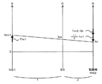
要求制動パワーPr*が制御用入力制限Win*以上のとき(要求制動パワーPr*が制動用入力制限Win*の範囲内のとき)には、エンジンブレーキを伴わずに走行すると判断し、エンジン22を自立運転するための自立運転指令をエンジンECU24に送信し(ステップS170)、モータMG1のトルク指令Tm1*に値0を設定し(ステップS180)、要求制動トルクTr*に設定したトルク指令Tm1*を動力分配統合機構30のギヤ比ρで除したものを加えて更に減速ギヤ35のギヤ比Grで除してモータMG2から出力すべきトルクの仮の値である仮トルクTm2tmpを次式(1)により計算し(ステップS220)、制御用入力制限Win*と設定したトルク指令Tm1*に現在のモータMG1の回転数Nm1を乗じて得られるモータMG1の消費電力(発電電力)との差分をモータMG2の回転数Nm2で割ることによりモータMG2から出力してもよいトルクの下限としてのトルク制限Tm2minを次式(2)により計算し(ステップS230)、設定した仮トルクTm2tmpを式(3)によりトルク制限Tm2minで制限してモータMG2のトルク指令Tm2*を設定し(ステップS240)、モータMG1,MG2のトルク指令Tm1*,Tm2*をモータECU40に送信して(ステップS250)、本ルーチンを終了する。自立運転指令を受信したエンジンECU24は、エンジン22が所定回転数(例えば、アイドル回転数など)で回転するよう吸入空気量制御や燃料噴射制御,点火制御などの制御を行なう。また、トルク指令Tm1*,Tm2*を受信したモータECU40は、トルク指令Tm1*でモータMG1が駆動されると共にトルク指令Tm2*でモータMG2が駆動されるようインバータ41,42のスイッチング素子のスイッチング制御を行なう。アクセルオフ時にエンジン22をアイドル運転しながら走行しているときの動力分配統合機構30の回転要素における回転数とトルクとの力学的な関係を示す共線図の一例を図5に示す。図中、左のS軸はモータMG1の回転数Nm1であるサンギヤ31の回転数を示し、C軸はエンジン22の回転数Neであるキャリア34の回転数を示し、R軸はモータMG2の回転数Nm2を減速ギヤ35のギヤ比Grで除したリングギヤ32の回転数Nrを示す。式(1)は、この共線図を用いれば容易に導くことができる。こうした制御により、エンジン22を自立運転しながら(エンジンブレーキを伴わずに)駆動軸としてのリングギヤ軸32aに要求制動トルクTr*に基づく制動トルクを出力して走行することができる。なお、この場合、モータMG2の回生駆動により生じる電力はバッテリ50に充電される。
When the required braking power Pr * is equal to or greater than the control input limit Win * (when the required braking power Pr * is within the range of the braking input limit Win *), it is determined that the vehicle travels without engine braking, and the
Tm2tmp=(Tr*+Tm1*/ρ)/Gr (1)
Tm2min=(Win*-Tm1*・Nm1)/Nm2 (2)
Tm2*=max(Tm2tmp,Tm2min) (3)
Tm2tmp = (Tr * + Tm1 * / ρ) / Gr (1)
Tm2min = (Win * -Tm1 * ・ Nm1) / Nm2 (2)
Tm2 * = max (Tm2tmp, Tm2min) (3)
ステップS160で要求制動パワーPr*が制御用入力制限Win*未満のとき(要求制動パワーPr*が制動用入力制限Win*の範囲外のとき)には、エンジンブレーキを伴って走行すると判断し、エンジン22の燃料噴射を停止するための燃料カット指令をエンジンECU24に送信すると共に(ステップS190)、シフトポジションSPと車速Vとに基づいてエンジン22の目標回転数Ne*を設定する(ステップS200)。燃料カット指令を受信したエンジンECU24は、燃料噴射制御や点火制御を停止する。また、エンジン22の目標回転数Ne*は、実施例では、シフトポジションSPと車速Vと目標回転数Ne*との関係を予め定めて目標回転数設定用マップとしてROM74に記憶しておき、シフトポジションSPと車速Vとが与えられると記憶したマップから対応する目標回転数Ne*を導出して設定するものとした。図6に目標回転数設定用マップの一例を示す。目標回転数Ne*は、図示するように、シフトポジションSPがSポジションのときにDポジションのときに比して大きくなる傾向に、且つ、シフトポジションSPがSポジションのときに、手動の有段変速機を備える車両のエンジンブレーキに近似するよう、車速Vが大きいほど大きくなる傾向で且つシフトポジションSPがS6からS1へ小さくなるほど大きくなる傾向に設定するものとした。
When the required braking power Pr * is less than the control input limit Win * in step S160 (when the required braking power Pr * is out of the range of the braking input limit Win *), it is determined that the vehicle travels with the engine brake, A fuel cut command for stopping fuel injection of the
こうしてエンジン22の目標回転数Ne*を設定すると、エンジン22の目標回転数Ne*とモータMG2の回転数Nm2と動力分配統合機構30のギヤ比ρと減速ギヤ35のギヤ比Grとを用いて次式(4)によりモータMG1の目標回転数Nm1*を計算すると共に計算した目標回転数Nm1*と入力したモータMG1の回転数Nm1とエンジン22の目標トルクTe*と動力分配統合機構30のギヤ比ρとに基づいて式(5)によりモータMG1のトルク指令Tm1*を計算し(ステップS210)、モータMG2のトルク指令Tm2*を設定し(ステップS220〜S240)、モータMG1,MG2のトルク指令Tm1*,Tm2*をモータECU40に送信して(ステップS250)、本ルーチンを終了する。ここで、式(4)は、動力分配統合機構30の回転要素に対する力学的な関係式である。アクセルオフ時にエンジンブレーキを伴って走行しているときの動力分配統合機構30の回転要素における回転数とトルクとの力学的な関係を示す共線図の一例を図7に示す。式(4)は、この共線図を用いれば容易に導くことができる。また、式(5)は、モータMG1を目標回転数Nm1*で回転させるためのフィードバック制御における関係式であり、式(5)中、右辺第2項の「k1」は比例項のゲインであり、右辺第3項の「k2」は積分項のゲインである。こうした制御により、エンジンブレーキを伴って駆動軸としてのリングギヤ軸32aに要求制動トルクTr*に基づく制動トルクを出力して走行することができる。
When the target rotational speed Ne * of the
Nm1*=Ne*・(1+ρ)/ρ-Nm2/(Gr・ρ) (4)
Tm1*=-ρ・Te*/(1+ρ)+k1・(Nm1*-Nm1)+k2・∫(Nm1*-Nm1)dt (5)
Nm1 * = Ne * ・ (1 + ρ) / ρ-Nm2 / (Gr ・ ρ) (4)
Tm1 * =-ρ ・ Te * / (1 + ρ) + k1 ・ (Nm1 * -Nm1) + k2 ・ ∫ (Nm1 * -Nm1) dt (5)
ステップS120でシフトポジションSPがSポジションのときには、触媒温度Tcを閾値Tcrefと比較する(ステップS140)。ここで、閾値Tcrefは、浄化触媒134aが活性化する温度範囲の下限として定められるものであり、例えば、400℃や450℃,500℃などを用いることができる。触媒温度Tcが閾値Tcref以上のときには、浄化触媒134aが活性化していると判断し、所定電力Wsを制御用入力制限Win*として設定し(ステップS150)、ステップS160〜S250の処理を実行して本ルーチンを終了する。ここで、所定電力Wsは、アクセルオフ時にエンジンブレーキを用いやすくすると共にバッテリ50が満充電に近い高残容量状態(例えば、70%や80%など)になるまでの時間を長くする電力としてバッテリ50の特性などに基づいて予め実験などにより定めることができ、バッテリ50の入力制限Winに比して大きい(絶対値が小さい)値、即ち、シフトポジションSPとしてSポジションが選択されていないときに比して大きい値が用いられる。したがって、この場合、シフトポジションSPがDポジションのときに比してエンジンブレーキが用いられやすくなり、運転者に良好なフィーリングを与えることができる。
When the shift position SP is the S position in step S120, the catalyst temperature Tc is compared with the threshold value Tcref (step S140). Here, the threshold value Tcref is determined as the lower limit of the temperature range in which the
ステップS140で触媒温度Tcが閾値Tcref未満のときには、浄化触媒134aが活性化していないと判断し、バッテリ50の入力制限Winを制御用入力制限Win*として設定し(ステップS130)、ステップS160〜S250の処理を実行して本ルーチンを終了する。浄化触媒134aが活性化していない状態でのアクセルオフ時にエンジンブレーキを用いると、その後にアクセルペダル83が踏み込まれてエンジン22の燃料噴射を再開する際にエンジン22の燃焼化の安定化などの理由によって燃料の増量補正を行なったときに、エンジン22からの排気を浄化触媒134aで十分に浄化できずにエミッションの悪化を招くおそれがある。これに対して、実施例では、浄化触媒134aが活性化していない状態でのアクセルオフ時には、浄化触媒134aが活性化しているときに比して小さい(絶対値が大きい)制御用入力制限Win*を用いるから、エンジンブレーキが用いられにくくなる即ちエンジン22が自立運転されやすくなり、エミッションの悪化を抑制することができる。
When the catalyst temperature Tc is lower than the threshold value Tcref in step S140, it is determined that the
以上説明した実施例のハイブリッド自動車20によれば、シフトポジションSPがSポジションでのアクセルオフ時において、触媒温度Tcが閾値Tcref以上のときには要求制動トルクTr*に応じた要求制動パワーPr*がバッテリ50の入力制限Winより大きい(絶対値が小さい)所定電力Ws以上のときにエンジン22を自立運転しながら(エンジンブレーキを伴わずに)リングギヤ軸32aに要求制動トルクTr*に基づく制動トルクを出力して走行するようエンジン22とモータMG1,MG2とを制御すると共に要求制動パワーPr*が所定電力Ws未満のときにいわゆるエンジンブレーキを伴って駆動軸としてのリングギヤ軸32aに要求制動トルクTr*に基づく制動トルクを出力して走行するようエンジン22とモータMG1,MG2とを制御し、触媒温度Tcが閾値Tcref未満のときには要求制動パワーPr*がバッテリ50の入力制限Win以上のときにエンジン22を自立運転しながらリングギヤ軸32aに要求制動トルクTr*に基づく制動トルクを出力して走行するようエンジン22とモータMG1,MG2とを制御すると共に要求制動パワーPr*がバッテリ50の入力制限Win未満のときにいわゆるエンジンブレーキを伴って駆動軸としてのリングギヤ軸32aに要求制動トルクTr*に基づく制動トルクを出力して走行するようエンジン22とモータMG1,MG2とを制御するから、触媒温度Tcが閾値Tcref以上のときにはエンジンブレーキが用いられやすくなり運転者に良好なフィーリングを与えることができ、触媒温度Tcが閾値Tcref未満のときにはエンジン22の燃料噴射が停止されにくくなりエミッションの悪化を抑制することができる。
According to the hybrid vehicle 20 of the embodiment described above, when the accelerator position is off at the shift position SP at the S position, the required braking power Pr * corresponding to the required braking torque Tr * is the battery when the catalyst temperature Tc is equal to or higher than the threshold value Tcref. A braking torque based on the required braking torque Tr * is output to the
実施例のハイブリッド自動車20では、触媒温度Tcを考慮せずに要求制動トルクTr*を設定するものとしたが、シフトポジションSPがSポジションのときには、触媒温度Tcを考慮して要求制動トルクTr*を設定するものとしてもよい。この場合、例えば、シフトポジションSPがSポジションのときにおいて、触媒温度Tcが閾値Tcref以上のときには実施例と同様にS1〜S6に応じて要求制動トルクTr*を設定し、触媒温度Tcが閾値Tcref未満のときにはシフトポジションSPがDポジションのときと同一の要求制動トルクTr*を設定するものとしてもよい。こうすれば、シフトポジションSPがSポジションのときにおいて、浄化触媒134aが活性化していないときに、浄化触媒134aが活性化しているときに比して大きい(制動トルクとしては小さい)要求制動トルクTr*が設定されるから、エンジンブレーキがより用いられにくくなる即ちエンジン22がより自立運転されやすくなり、エミッションの悪化をより抑制することができる。なお、シフトポジションSPがSポジションで触媒温度Tcが閾値Tcref未満のときには、シフトポジションSPがDポジションのときと同一の要求制動トルクTr*を設定するものに限られず、S1〜S6に応じたトルクよりも大きなトルク(制動側としては小さなトルク)を要求制動トルクTr*として設定するものであればよい。また、シフトポジションSPがSポジションで触媒温度Tcが閾値Tcref未満のときにおいてS1〜S6に応じたトルクよりも大きなトルクを要求制動トルクTr*として設定する場合には、触媒温度Tcに拘わらず所定電力Psを制御用入力制限Win*として設定するものとしてもよい。こうしたとしても、要求制動トルクTr*を制動側として小さなトルクとすることにより、触媒温度Tcが閾値Tcref以上のときに比してエンジンブレーキが用いられにくくなる即ちエンジン22が自立運転されやすくなり、エミッションの悪化を抑制することができる。
In the hybrid vehicle 20 of the embodiment, the required braking torque Tr * is set without considering the catalyst temperature Tc. However, when the shift position SP is the S position, the required braking torque Tr * is considered in consideration of the catalyst temperature Tc. May be set. In this case, for example, when the shift position SP is the S position and the catalyst temperature Tc is equal to or higher than the threshold value Tcref, the required braking torque Tr * is set according to S1 to S6 as in the embodiment, and the catalyst temperature Tc is set to the threshold value Tcref. If it is less, the same required braking torque Tr * may be set as when the shift position SP is the D position. In this way, when the shift position SP is at the S position, the required braking torque Tr that is larger (smaller as the braking torque) than when the
実施例のハイブリッド自動車20では、シフトポジションSPがSポジションで触媒温度Tcが閾値Tcref未満のときには、バッテリ50の入力制限Winを制御用入力制限Win*として設定するものとしたが、これに限られず、バッテリ50の入力制限Win以上で所定電力Ws未満の範囲(絶対値としては入力制限Winの絶対値以下で所定電力Wsの絶対値より大きい範囲)内で制御用入力制限Win*を設定するものであればよい。
In the hybrid vehicle 20 of the embodiment, when the shift position SP is the S position and the catalyst temperature Tc is less than the threshold value Tcref, the input limit Win of the
実施例のハイブリッド自動車20では、制動用のポジションとしてシーケンシャルポジション(Sポジション)を想定したが、Sポジションに代えてまたは加えてDポジションに比してアクセルオフ時の要求制動トルクTr*が小さくなる(制動トルクとして大きくなる)単一段の制動用のポジション(Bポジション)を備える場合には、シフトポジションSPがBポジションにあってアクセルオフのときに、シフトポジションSPがSポジションにあってアクセルオフのときと同様の制御を行なえばよい。 In the hybrid vehicle 20 of the embodiment, a sequential position (S position) is assumed as a braking position, but the required braking torque Tr * when the accelerator is off is smaller than the D position instead of or in addition to the S position. When a single-stage braking position (B position) is provided (which increases as braking torque), when the shift position SP is in the B position and the accelerator is off, the shift position SP is in the S position and the accelerator is off. The same control as in the above may be performed.
実施例のハイブリッド自動車20では、浄化装置134に取り付けられた温度センサ135cにより触媒温度Tcを検出するものとしたが、温度センサ135cを備えず、吸入空気量Qaの積算値や吸気温Ta,冷却水温Twなどに基づいて浄化触媒134aの温度を推定するものとしてもよい。
In the hybrid vehicle 20 of the embodiment, the catalyst temperature Tc is detected by the
実施例のハイブリッド自動車20では、モータMG2の動力を減速ギヤ35により変速してリングギヤ軸32aに出力するものとしたが、図8の変形例のハイブリッド自動車120に例示するように、モータMG2の動力をリングギヤ軸32aが接続された車軸(駆動輪63a,63bが接続された車軸)とは異なる車軸(図8における車輪64a,64bに接続された車軸)に出力するものとしてもよい。
In the hybrid vehicle 20 of the embodiment, the power of the motor MG2 is shifted by the
また、こうしたハイブリッド自動車に適用するものに限定されるものではなく、自動車以外の車両の形態としてもよい。また、ハイブリッド車の制御方法の形態としてもよい。 Moreover, it is not limited to what is applied to such a hybrid vehicle, It is good also as forms of vehicles other than a motor vehicle. Moreover, it is good also as a form of the control method of a hybrid vehicle.
実施例の主要な要素と課題を解決するための手段の欄に記載した発明の主要な要素との対応関係について説明する。実施例では、浄化触媒134aを有する浄化装置134が排気系に取り付けられたエンジン22が「内燃機関」に相当し、モータMG1が「発電機」に相当し、動力分配統合機構30が「3軸式動力入出力手段」に相当し、モータMG2が「電動機」に相当し、バッテリ50が「蓄電手段」に相当し、シフトポジションSPがSポジションでのアクセルオフ時において、触媒温度Tcが閾値Tcref以上のときには要求制動トルクTr*に応じた要求制動パワーPr*がバッテリ50の入力制限Winより大きい(絶対値が小さい)所定電力Ws以上のときにエンジン22を自立運転しながら(エンジンブレーキを伴わずに)リングギヤ軸32aに要求制動トルクTr*に基づく制動トルクを出力して走行するよう自立運転指令をエンジンECU24に送信したりモータMG1,MG2のトルク指令Tm1*,Tm2*を設定してモータECU40に送信したりすると共に要求制動パワーPr*が所定電力Ws未満のときにいわゆるエンジンブレーキを伴って駆動軸としてのリングギヤ軸32aに要求制動トルクTr*に基づく制動トルクを出力して走行するよう燃料カット指令をエンジンECU24に送信したりモータMG1,MG2のトルク指令Tm1*,Tm2*を設定してモータECU40に送信したりし、触媒温度Tcが閾値Tcref未満のときには要求制動パワーPr*がバッテリ50の入力制限Win以上のときにエンジン22を自立運転しながらリングギヤ軸32aに要求制動トルクTr*に基づく制動トルクを出力して走行するよう自立運転指令をエンジンECU24に送信したりモータMG1,MG2のトルク指令Tm1*,Tm2*を設定してモータECU40に送信したりすると共に要求制動パワーPr*がバッテリ50の入力制限Winのときにいわゆるエンジンブレーキを伴って駆動軸としてのリングギヤ軸32aに要求制動トルクTr*に基づく制動トルクを出力して走行するよう燃料カット指令をエンジンECU24に送信したりモータMG1,MG2のトルク指令Tm1*,Tm2*を設定してモータECU40に送信したりする図3のアクセルオフ時制御ルーチンを実行するハイブリッド用電子制御ユニット70と、自立運転指令に基づいてエンジン22を制御したり燃料カット指令に基づいて燃料噴射制御や停止制御を停止したりするエンジンECU24と、トルク指令Tm1*,Tm2*に基づいてモータMG1,MG2を制御するモータECU40と、が「アクセルオフ時制御手段」に相当する。
The correspondence between the main elements of the embodiment and the main elements of the invention described in the column of means for solving the problems will be described. In the embodiment, the
ここで、「内燃機関」としては、ガソリンまたは軽油などの炭化水素系の燃料により動力を出力する内燃機関に限定されるものではなく、排気系に排気を浄化する浄化触媒を有する浄化装置が取り付けられたものであれば如何なるものとしても構わない。「発電機」としては、同期発電電動機として構成されたモータMG1に限定されるものではなく、誘導電動機など、動力を入出力可能なものであれば如何なるタイプの発電機であっても構わない。「3軸式動力入出力手段」としては、動力分配統合機構30に限定されるものではなく、ダブルピニオン式の遊星歯車機構を用いるものや複数の遊星歯車機構を組み合わせて4以上の軸に接続されるものやデファレンシャルギヤのように遊星歯車とは異なる作動作用を有するものなど、車軸に連結された駆動軸と内燃機関の出力軸と発電機の回転軸との3軸に接続され、3軸のうちのいずれか2軸に入出力される動力に基づいて残余の軸に動力を入出力するものであれば如何なるものとしても構わない。「蓄電手段」としては、二次電池としてのバッテリ50に限定されるものではなく、キャパシタなど、発電機や電動機と電力のやりとりが可能なものであれば如何なるものとしても構わない。「制御手段」としては、シフトポジションSPがSポジションでのアクセルオフ時において、触媒温度Tcが閾値Tcref以上のときには要求制動トルクTr*に応じた要求制動パワーPr*がバッテリ50の入力制限Winより大きい(絶対値が小さい)所定電力Ws以上のときにエンジン22を自立運転しながら(エンジンブレーキを伴わずに)リングギヤ軸32aに要求制動トルクTr*に基づく制動トルクを出力して走行するようエンジン22とモータMG1,MG2とを制御すると共に要求制動パワーPr*が所定電力Ws未満のときにいわゆるエンジンブレーキを伴って駆動軸としてのリングギヤ軸32aに要求制動トルクTr*に基づく制動トルクを出力して走行するようエンジン22とモータMG1,MG2とを制御し、触媒温度Tcが閾値Tcref未満のときには要求制動パワーPr*がバッテリ50の入力制限Win以上のときにエンジン22を自立運転しながらリングギヤ軸32aに要求制動トルクTr*に基づく制動トルクを出力して走行するようエンジン22とモータMG1,MG2とを制御すると共に要求制動パワーPr*がバッテリ50の入力制限Win未満のときにいわゆるエンジンブレーキを伴って駆動軸としてのリングギヤ軸32aに要求制動トルクTr*に基づく制動トルクを出力して走行するようエンジン22とモータMG1,MG2とを制御するものに限定されるものではなく、シフトポジションSPがSポジションのときにおいて、触媒温度Tcが閾値Tcref以上のときにはS1〜S6に応じて要求制動トルクTr*を設定し、触媒温度Tcが閾値Tcref未満のときにはシフトポジションSPがDポジションのときと同一の要求制動トルクTr*を設定するものとするなど、通常の走行用ポジションに比してアクセルオフ時に大きな制動力が要求される制動用ポジションにシフトポジションがあってアクセルオフのとき、浄化触媒の温度が浄化触媒が活性化する温度範囲の下限として定められた下限温度以上のときには内燃機関の燃料噴射の停止および発電機による内燃機関のモータリングを伴って車両に要求される要求制動力により走行するよう内燃機関と発電機と電動機とを制御するモータリング制動制御と内燃機関の燃料噴射を伴って要求制動力により走行するよう内燃機関と発電機と電動機とを制御する運転制動制御とのうちモータリング制動制御を優先して実行し、浄化触媒の温度が下限温度未満のときにはモータリング制動制御と運転制動制御とのうち運転制動制御を優先して実行するものであれば如何なるものとしても構わない。
Here, the “internal combustion engine” is not limited to an internal combustion engine that outputs power using a hydrocarbon fuel such as gasoline or light oil, but a purification device having a purification catalyst for purifying exhaust gas is attached to the exhaust system. As long as it is given, it does not matter. The “generator” is not limited to the motor MG1 configured as a synchronous generator motor, and may be any type of generator as long as it can input and output power, such as an induction motor. The “3-axis power input / output means” is not limited to the power distribution /
なお、実施例の主要な要素と課題を解決するための手段の欄に記載した発明の主要な要素との対応関係は、実施例が課題を解決するための手段の欄に記載した発明を実施するための形態を具体的に説明するための一例であることから、課題を解決するための手段の欄に記載した発明の要素を限定するものではない。即ち、課題を解決するための手段の欄に記載した発明についての解釈はその欄の記載に基づいて行なわれるべきものであり、実施例は課題を解決するための手段の欄に記載した発明の具体的な一例に過ぎないものである。 The correspondence between the main elements of the embodiment and the main elements of the invention described in the column of means for solving the problem is the same as that of the embodiment described in the column of means for solving the problem. Therefore, the elements of the invention described in the column of means for solving the problems are not limited. That is, the interpretation of the invention described in the column of means for solving the problems should be made based on the description of the column, and the examples are those of the invention described in the column of means for solving the problems. It is only a specific example.
以上、本発明を実施するための形態について実施例を用いて説明したが、本発明はこうした実施例に何等限定されるものではなく、本発明の要旨を逸脱しない範囲内において、種々なる形態で実施し得ることは勿論である。 As mentioned above, although the form for implementing this invention was demonstrated using the Example, this invention is not limited at all to such an Example, In the range which does not deviate from the summary of this invention, it is with various forms. Of course, it can be implemented.
本発明は、ハイブリッド車の製造産業に利用可能である。 The present invention is applicable to the hybrid vehicle manufacturing industry.
20,120 ハイブリッド自動車、22 エンジン、24 エンジン用電子制御ユニット(エンジンECU)、24a CPU、24b ROM、24c RAM、26 クランクシャフト、28 ダンパ、30 動力分配統合機構、31 サンギヤ、32 リングギヤ、32a リングギヤ軸、33 ピニオンギヤ、34 キャリア、35 減速ギヤ、40 モータ用電子制御ユニット(モータECU)、41,42 インバータ、43,44 回転位置検出センサ、50 バッテリ、51a 電圧センサ、51b 電流センサ、51c 温度センサ、52 バッテリ用電子制御ユニット(バッテリECU)、54 電力ライン、60 ギヤ機構、62 デファレンシャルギヤ、63a,63b 駆動輪、64a,64b 車輪、70 ハイブリッド用電子制御ユニット、72 CPU、74 ROM、76 RAM、80 イグニッションスイッチ、81 シフトレバー、82 シフトポジションセンサ、83 アクセルペダル、84 アクセルペダルポジションセンサ、85 ブレーキペダル、86 ブレーキペダルポジションセンサ、88 車速センサ、122 エアクリーナ、124 スロットルバルブ、126 燃料噴射弁、128 吸気バルブ、130 点火プラグ、132 ピストン、134 浄化装置、134a 浄化触媒、135a 空燃比センサ、135b 酸素センサ、135c 温度センサ、136,スロットルモータ、138 イグニッションコイル、140 クランクポジションセンサ、142 水温センサ、143 圧力センサ、144 カムポジションセンサ、146 スロットルバルブポジションセンサ、148 エアフローメータ、149 温度センサ、150 可変バルブタイミング機構、MG1,MG2 モータ。 20,120 Hybrid vehicle, 22 engine, 24 engine electronic control unit (engine ECU), 24a CPU, 24b ROM, 24c RAM, 26 crankshaft, 28 damper, 30 power distribution integrated mechanism, 31 sun gear, 32 ring gear, 32a ring gear Shaft, 33 pinion gear, 34 carrier, 35 reduction gear, 40 motor electronic control unit (motor ECU), 41, 42 inverter, 43, 44 rotational position detection sensor, 50 battery, 51a voltage sensor, 51b current sensor, 51c temperature sensor , 52 battery electronic control unit (battery ECU), 54 power line, 60 gear mechanism, 62 differential gear, 63a, 63b driving wheel, 64a, 64b wheel, 70 electronic control for hybrid Control unit, 72 CPU, 74 ROM, 76 RAM, 80 ignition switch, 81 shift lever, 82 shift position sensor, 83 accelerator pedal, 84 accelerator pedal position sensor, 85 brake pedal, 86 brake pedal position sensor, 88 vehicle speed sensor, 122 Air cleaner, 124 throttle valve, 126 fuel injection valve, 128 intake valve, 130 spark plug, 132 piston, 134 purification device, 134a purification catalyst, 135a air-fuel ratio sensor, 135b oxygen sensor, 135c temperature sensor, 136, throttle motor, 138 ignition Coil, 140 Crank position sensor, 142 Water temperature sensor, 143 Pressure sensor, 144 Cam position sensor, 146 Throttle bar Bed position sensor, 148 an air flow meter, 149 temperature sensor, 150 a variable valve timing mechanism, MG1, MG2 motor.
Claims (4)
動力を入出力可能な発電機と、
車軸に連結された駆動軸と前記内燃機関の出力軸と前記発電機の回転軸との3軸に接続され、該3軸のうちのいずれか2軸に入出力される動力に基づいて残余の軸に動力を入出力する3軸式動力入出力手段と、
前記駆動軸に動力を入出力可能な電動機と、
前記発電機および前記電動機と電力のやりとりが可能な蓄電手段と、
通常の走行用ポジションに比してアクセルオフ時に大きな制動力が要求される制動用ポジションにシフトポジションがあってアクセルオフのとき、前記浄化触媒の温度が該浄化触媒が活性化する温度範囲の下限として定められた下限温度以上のときには前記内燃機関の燃料噴射の停止および前記発電機による前記内燃機関のモータリングを伴って車両に要求される要求制動力により走行するよう前記内燃機関と前記発電機と前記電動機とを制御するモータリング制動制御と前記内燃機関の燃料噴射を伴って前記要求制動力により走行するよう前記内燃機関と前記発電機と前記電動機とを制御する運転制動制御とのうち前記モータリング制動制御を優先して実行し、前記浄化触媒の温度が前記下限温度未満のときには前記モータリング制動制御と前記運転制動制御とのうち前記運転制動制御を優先して実行するアクセルオフ時制御手段と、
を備え、
前記アクセルオフ時制御手段は、前記シフトポジションが前記制動用ポジションにあってアクセルオフのとき、前記浄化触媒の温度が前記下限温度以上のときには前記要求制動力に応じた要求制動パワーが第1のパワー範囲内のときに前記自立運転制動制御を実行すると共に前記要求制動パワーが前記第1のパワー範囲外のときに前記モータリング制動制御を実行し、前記浄化触媒の温度が前記下限温度未満のときには前記要求制動パワーが前記第1のパワー範囲よりも広い第2のパワー範囲内のときに前記自立運転制動制御を実行すると共に前記要求制動パワーが前記第2のパワー範囲外のときに前記モータリング制動制御を実行する手段である、
ハイブリッド車。 An internal combustion engine having a purification device having a purification catalyst for purifying exhaust gas in an exhaust system;
A generator capable of inputting and outputting power;
It is connected to three shafts, that is, a drive shaft coupled to an axle, an output shaft of the internal combustion engine, and a rotating shaft of the generator, and the remaining power is determined based on power input / output to / from any two of the three shafts. 3-axis power input / output means for inputting / outputting power to the shaft;
An electric motor capable of inputting and outputting power to the drive shaft;
Power storage means capable of exchanging electric power with the generator and the motor;
The lower limit of the temperature range in which the temperature of the purification catalyst is activated when the shift position is at the braking position where a large braking force is required when the accelerator is off compared to the normal driving position and the accelerator is off. The internal combustion engine and the generator so that the vehicle travels with the required braking force required for the vehicle with stop of fuel injection of the internal combustion engine and motoring of the internal combustion engine by the generator Motoring braking control for controlling the motor and the motor, and driving braking control for controlling the internal combustion engine, the generator and the motor so as to travel with the required braking force with fuel injection of the internal combustion engine. Priority is given to motoring braking control, and the motoring braking control is performed when the temperature of the purification catalyst is lower than the lower limit temperature. An accelerator-off time control means for performing preferentially the operation braking control of said operating brake control,
Equipped with a,
The accelerator-off-time control means is configured such that when the shift position is in the braking position and the accelerator is off, and when the temperature of the purification catalyst is equal to or higher than the lower limit temperature, the requested braking power corresponding to the requested braking force The autonomous driving braking control is executed when within the power range, and the motoring braking control is executed when the required braking power is outside the first power range, and the temperature of the purification catalyst is less than the lower limit temperature. Sometimes, when the required braking power is within a second power range that is wider than the first power range, the autonomous driving braking control is executed, and when the required braking power is outside the second power range, the motor Means for executing ring braking control;
Hybrid car.
前記第1のパワー範囲および前記第2のパワー範囲は、前記内燃機関のモータリングを伴わずに前記電動機の回生制動によって前記要求制動力により走行する範囲として定められるパワー範囲である、
ハイブリッド車。 The hybrid vehicle according to claim 1 ,
The first power range and the second power range are power ranges that are determined as a range that travels by the required braking force by regenerative braking of the electric motor without motoring of the internal combustion engine.
Hybrid car.
前記アクセルオフ時制御手段は、前記シフトポジションが前記制動用ポジションにあってアクセルオフのときにおいて、前記浄化触媒の温度が前記下限温度未満のときには、前記浄化触媒の温度が前記下限温度以上のときに比して小さな制動力を前記要求制動力とする手段である、
ハイブリッド車。 A hybrid vehicle according to claim 1 or 2 ,
The accelerator-off-time control means is configured such that when the shift position is at the braking position and the accelerator is off, the temperature of the purification catalyst is lower than the lower limit temperature, and the temperature of the purification catalyst is equal to or higher than the lower limit temperature. A means for setting the required braking force to a braking force smaller than
Hybrid car.
通常の走行用ポジションに比してアクセルオフ時に大きな制動力が要求される制動用ポジションにシフトポジションがあってアクセルオフのとき、前記浄化触媒の温度が該浄化触媒が活性化する温度範囲の下限として定められた下限温度以上のときには前記内燃機関の燃料噴射の停止および前記発電機による前記内燃機関のモータリングを伴って車両に要求される要求制動力により走行するよう前記内燃機関と前記発電機と前記電動機とを制御するモータリング制動制御と前記内燃機関の燃料噴射を伴って前記要求制動力により走行するよう前記内燃機関と前記発電機と前記電動機とを制御する運転制動制御とのうち前記モータリング制動制御を優先して実行し、前記浄化触媒の温度が前記下限温度未満のときには前記モータリング制動制御と前記運転制動制御とのうち前記運転制動制御を優先して実行するステップを含み、
前記ステップは、前記シフトポジションが前記制動用ポジションにあってアクセルオフのとき、前記浄化触媒の温度が前記下限温度以上のときには前記要求制動力に応じた要求制動パワーが第1のパワー範囲内のときに前記自立運転制動制御を実行すると共に前記要求制動パワーが前記第1のパワー範囲外のときに前記モータリング制動制御を実行し、前記浄化触媒の温度が前記下限温度未満のときには前記要求制動パワーが前記第1のパワー範囲よりも広い第2のパワー範囲内のときに前記自立運転制動制御を実行すると共に前記要求制動パワーが前記第2のパワー範囲外のときに前記モータリング制動制御を実行するステップである、
ことを特徴とするハイブリッド車の制御方法。
An internal combustion engine having a purification device having a purification catalyst for purifying exhaust gas in an exhaust system, a generator capable of inputting and outputting power, a drive shaft connected to an axle, an output shaft of the internal combustion engine, and the generator A three-axis power input / output means connected to the three axes of the rotating shaft and inputting / outputting power to / from the remaining shaft based on power input / output to / from any two of the three axes; A control method for a hybrid vehicle comprising: an electric motor capable of inputting / outputting power; and an electric storage means capable of exchanging electric power with the electric generator and the electric motor,
The lower limit of the temperature range in which the temperature of the purification catalyst is activated when the shift position is at the braking position where a large braking force is required when the accelerator is off compared to the normal driving position and the accelerator is off. The internal combustion engine and the generator so that the vehicle travels with the required braking force required for the vehicle with stop of fuel injection of the internal combustion engine and motoring of the internal combustion engine by the generator Motoring braking control for controlling the motor and the motor, and driving braking control for controlling the internal combustion engine, the generator and the motor so as to travel with the required braking force with fuel injection of the internal combustion engine. Priority is given to motoring braking control, and the motoring braking control is performed when the temperature of the purification catalyst is lower than the lower limit temperature. Comprising: performing preferentially the operation braking control of said operating brake control,
In the step, when the shift position is in the braking position and the accelerator is off, the required braking power corresponding to the required braking force is within a first power range when the temperature of the purification catalyst is equal to or higher than the lower limit temperature. When the autonomous braking control is executed, the motoring braking control is executed when the required braking power is outside the first power range, and the required braking is performed when the temperature of the purification catalyst is less than the lower limit temperature. The autonomous driving braking control is executed when the power is within a second power range that is wider than the first power range, and the motoring braking control is performed when the required braking power is outside the second power range. Is the step to perform,
A control method for a hybrid vehicle.
Priority Applications (1)
| Application Number | Priority Date | Filing Date | Title |
|---|---|---|---|
| JP2009177936A JP5246090B2 (en) | 2009-07-30 | 2009-07-30 | Hybrid vehicle and control method thereof |
Applications Claiming Priority (1)
| Application Number | Priority Date | Filing Date | Title |
|---|---|---|---|
| JP2009177936A JP5246090B2 (en) | 2009-07-30 | 2009-07-30 | Hybrid vehicle and control method thereof |
Publications (2)
| Publication Number | Publication Date |
|---|---|
| JP2011031674A JP2011031674A (en) | 2011-02-17 |
| JP5246090B2 true JP5246090B2 (en) | 2013-07-24 |
Family
ID=43761199
Family Applications (1)
| Application Number | Title | Priority Date | Filing Date |
|---|---|---|---|
| JP2009177936A Expired - Fee Related JP5246090B2 (en) | 2009-07-30 | 2009-07-30 | Hybrid vehicle and control method thereof |
Country Status (1)
| Country | Link |
|---|---|
| JP (1) | JP5246090B2 (en) |
Families Citing this family (3)
| Publication number | Priority date | Publication date | Assignee | Title |
|---|---|---|---|---|
| JP2013112320A (en) * | 2011-12-01 | 2013-06-10 | Toyota Motor Corp | Hybrid vehicle |
| JP5632882B2 (en) * | 2012-07-09 | 2014-11-26 | 本田技研工業株式会社 | Catalyst warm-up control device for hybrid vehicle |
| JP6544342B2 (en) * | 2016-11-29 | 2019-07-17 | トヨタ自動車株式会社 | Hybrid car |
Family Cites Families (2)
| Publication number | Priority date | Publication date | Assignee | Title |
|---|---|---|---|---|
| JP4435085B2 (en) * | 2005-12-27 | 2010-03-17 | 三菱自動車工業株式会社 | In-cylinder injection type spark ignition internal combustion engine |
| JP4175370B2 (en) * | 2006-01-13 | 2008-11-05 | トヨタ自動車株式会社 | Hybrid vehicle and control method thereof |
-
2009
- 2009-07-30 JP JP2009177936A patent/JP5246090B2/en not_active Expired - Fee Related
Also Published As
| Publication number | Publication date |
|---|---|
| JP2011031674A (en) | 2011-02-17 |
Similar Documents
| Publication | Publication Date | Title |
|---|---|---|
| JP4552921B2 (en) | Hybrid vehicle and control method thereof | |
| JP4321619B2 (en) | Vehicle and control method thereof | |
| JP4197038B2 (en) | Hybrid vehicle and control method thereof | |
| JP4850801B2 (en) | INTERNAL COMBUSTION ENGINE DEVICE, VEHICLE MOUNTING THE SAME, AND METHOD FOR CONTROLLING INTERNAL COMBUSTION ENGINE DEVICE | |
| JP2010179780A (en) | Hybrid vehicle and control method for the same | |
| JP4265673B2 (en) | POWER OUTPUT DEVICE, ITS CONTROL METHOD, AND VEHICLE | |
| JP2009280094A (en) | Power output device and method of controlling the same, and vehicle | |
| JP5904131B2 (en) | Hybrid vehicle control device and hybrid vehicle | |
| JP5716425B2 (en) | Hybrid car | |
| JP5218244B2 (en) | Hybrid car | |
| JP2010260392A (en) | Vehicle and control method therefor | |
| JP4196960B2 (en) | Power output apparatus, automobile equipped with the same, and control method therefor | |
| JP5246090B2 (en) | Hybrid vehicle and control method thereof | |
| JP2010083319A (en) | Hybrid vehicle and method for controlling the same | |
| JP2007309113A (en) | Power output device, vehicle mounted with the device and control method of power output device | |
| JP2010105626A (en) | Vehicle and control method therefor | |
| JP2010274739A (en) | Internal combustion engine device and hybrid vehicle | |
| JP4285552B2 (en) | Vehicle and control method thereof | |
| JP4438752B2 (en) | POWER OUTPUT DEVICE, ITS CONTROL METHOD, AND VEHICLE | |
| JP5494398B2 (en) | Hybrid car | |
| JP4311414B2 (en) | Vehicle and control method thereof | |
| JP5751185B2 (en) | Hybrid car | |
| JP2009274628A (en) | Hybrid vehicle and its control method | |
| JP2011084202A (en) | Power output device, hybrid vehicle equipped with the same, and control method for the power output device | |
| JP2009279965A (en) | Hybrid vehicle and method of controlling the same |
Legal Events
| Date | Code | Title | Description |
|---|---|---|---|
| A621 | Written request for application examination |
Free format text: JAPANESE INTERMEDIATE CODE: A621 Effective date: 20111018 |
|
| A131 | Notification of reasons for refusal |
Free format text: JAPANESE INTERMEDIATE CODE: A131 Effective date: 20121225 |
|
| A977 | Report on retrieval |
Free format text: JAPANESE INTERMEDIATE CODE: A971007 Effective date: 20121228 |
|
| A521 | Request for written amendment filed |
Free format text: JAPANESE INTERMEDIATE CODE: A523 Effective date: 20130116 |
|
| TRDD | Decision of grant or rejection written | ||
| A01 | Written decision to grant a patent or to grant a registration (utility model) |
Free format text: JAPANESE INTERMEDIATE CODE: A01 Effective date: 20130312 |
|
| A61 | First payment of annual fees (during grant procedure) |
Free format text: JAPANESE INTERMEDIATE CODE: A61 Effective date: 20130325 |
|
| R151 | Written notification of patent or utility model registration |
Ref document number: 5246090 Country of ref document: JP Free format text: JAPANESE INTERMEDIATE CODE: R151 |
|
| FPAY | Renewal fee payment (event date is renewal date of database) |
Free format text: PAYMENT UNTIL: 20160419 Year of fee payment: 3 |
|
| LAPS | Cancellation because of no payment of annual fees |