JP6183408B2 - Inkjet recording method - Google Patents
Inkjet recording method Download PDFInfo
- Publication number
- JP6183408B2 JP6183408B2 JP2015102521A JP2015102521A JP6183408B2 JP 6183408 B2 JP6183408 B2 JP 6183408B2 JP 2015102521 A JP2015102521 A JP 2015102521A JP 2015102521 A JP2015102521 A JP 2015102521A JP 6183408 B2 JP6183408 B2 JP 6183408B2
- Authority
- JP
- Japan
- Prior art keywords
- white
- ink composition
- ink
- layer
- pattern layer
- Prior art date
- Legal status (The legal status is an assumption and is not a legal conclusion. Google has not performed a legal analysis and makes no representation as to the accuracy of the status listed.)
- Active
Links
Images


Description
本発明は、パターン層(例えば、カラーパターン層、又は黒色若しくは灰色パターン層)と白色ベタ塗り層とを長尺状フィルム基材に記録するインクジェット記録方法、及びその記録方法によって得られた長尺状印刷物に関する。本発明によれば、白地にカラー画像を印刷する様式のパッケージ印刷におけるリモートプルーフィングを、廉価なインクジェット方式により高精度に実現することができる。 The present invention relates to an inkjet recording method for recording a pattern layer (for example, a color pattern layer, or a black or gray pattern layer) and a white solid coating layer on a long film substrate, and a long length obtained by the recording method. Related to printed matter. ADVANTAGE OF THE INVENTION According to this invention, the remote proofing in the package printing of the style which prints a color image on a white background can be implement | achieved with high precision by an inexpensive inkjet system.
お菓子類などの商品の包装では、包装用の紙製外箱を透明フィルムで覆い、その透明フィルムの一部分又は全体に、白地にカラー画像を配置した印刷を施すことが広く行われている。あるいは、包装用プラスチック製袋体の表面に、白地にカラー画像を配置した印刷を施すことも広く行われている。これらの印刷には、通常、オフセット印刷やフレキソ印刷が利用されている。
印刷業界では、高品質化だけでなくコストダウンや納期短縮が厳しく求められており、デザイン確定から本機印刷の開始に至るまで、デジタルデータの利用が進んでいる。例えば、印刷物製作のワークフローは、入稿データの作成、DDCP(Direct Digital Color Proofing)による校正、CTP(Computer To Plate)による刷版制作、及び本機印刷の順に工程が進行し、入稿データを確定するために行うDDCP校正作業でも、電子メールによるデジタルデータの送付が頻繁に行われている。
前記DDCP校正作業では、デジタルデータを電子メールで受領した校正者やデザイン発注者がコンピュータ画面上で校正作業や確認作業を行うだけでなく、実際に用紙に印刷を行って校正や確認を行うことがある。この場合の出力方式には、インクジェット方式、トナー方式、熱転写方式、あるいは網点方式などが用いられているが、白地にカラー画像を配置した印刷においては、最も廉価なインクジェット方式では、必ずしも満足な出力品質を得ることができないという問題があった。
In packaging of products such as confectionery, it is widely performed that a paper outer box for packaging is covered with a transparent film, and a part of or the whole of the transparent film is printed with a color image arranged on a white background. Alternatively, it is also widely performed to print a color image on a white background on the surface of a packaging plastic bag. For these printings, offset printing and flexographic printing are usually used.
In the printing industry, not only high quality but also cost reduction and delivery time reduction are strictly demanded, and the use of digital data is progressing from design confirmation to the start of printing on this machine. For example, in the workflow of print production, the process proceeds in the order of creation of input data, proofreading by DDCP (Direct Digital Color Proofing), plate production by CTP (Computer To Plate), and printing on this machine. Even in the DDCP calibration work to be performed, digital data is frequently sent by electronic mail.
In the DDCP calibration work, the proofreader who received the digital data by e-mail and the design orderer not only perform the calibration work and confirmation work on the computer screen, but also perform the calibration and confirmation by actually printing on the paper. There is. In this case, an ink jet method, a toner method, a thermal transfer method, a halftone dot method, or the like is used as the output method. However, in printing with a color image arranged on a white background, the cheapest ink jet method is not always satisfactory. There was a problem that the output quality could not be obtained.
一方、インクジェット記録用の白色インクとしては、中空ポリマー微粒子を含有するインクが提案されている(例えば、特許文献1又は特許文献2)。しかしながら、これらの中空ポリマー微粒子含有白色インクをインクジェット方式によるリモートプルーフィングに用いることは、従来全く提案されていない。 On the other hand, as white ink for inkjet recording, ink containing hollow polymer fine particles has been proposed (for example, Patent Document 1 or Patent Document 2). However, the use of these white inks containing hollow polymer fine particles for remote proofing by an ink jet method has never been proposed.
本発明者は、白地にカラー画像を配置した印刷物(例えば、オフセット印刷物)のリモートプルーフィングを実施する際の出力方式としてインクジェット方式を利用して、高品質の画像を得る方法を鋭意研究していたところ、長尺状フィルム基材を2つのインクジェットプリンタに連続的に案内して、パターン層(特に、カラーパターン層)と白色ベタ塗り層とを別々に記録することにより、目的を達成することができることを見出した。
本発明は、こうした知見に基づくものである。
The inventor has intensively studied a method for obtaining a high-quality image by using an inkjet method as an output method when performing remote proofing of a printed matter (for example, offset printed matter) in which a color image is arranged on a white background. As a result, the long film substrate is continuously guided to two inkjet printers, and the pattern layer (particularly, the color pattern layer) and the white solid coating layer are recorded separately to achieve the object. I found out that I can.
The present invention is based on these findings.
本発明は、長尺状フィルム基材の表面上に、白色ベタ塗り層と非白色パターン層とからなる印刷ユニットを、2つの液体吐出手段により記録する方法であって、(A)前記長尺状フィルム基材が不透明である場合に、第1の液体吐出手段によって白色ベタ塗り層を設け、その白色ベタ塗り層が乾燥した後に、その乾燥白色ベタ塗り層の上から、第2の液体吐出手段によって非白色パターン層を設けるか、(B)前記長尺状フィルム基材が透明である場合に、第1の液体吐出手段によって非白色パターン層を設け、その非白色パターン層が乾燥した後に、その乾燥非白色パターン層の上から、第2の液体吐出手段によって白色ベタ塗り層を設けるか、あるいは(C)前記長尺状フィルム基材が透明である場合に、その一方の表面に第1の液体吐出手段によって非白色パターン層又は白色ベタ塗り層を設け、続いて、その非白色パターン層又は白色ベタ塗り層に相当する位置のもう一方の表面に、第2の液体吐出手段によって白色ベタ塗り層を設ける又は非白色パターン層を設けることを特徴とする、前記のインクジェット記録方法に関する。 The present invention is a method of recording a printing unit comprising a white solid coating layer and a non-white pattern layer on the surface of a long film substrate by two liquid discharge means, and (A) the long film When the film-like film substrate is opaque, a white solid coating layer is provided by the first liquid ejection means, and after the white solid coating layer is dried, the second liquid ejection is performed on the dried white solid coating layer. A non-white pattern layer is provided by means, or (B) when the long film substrate is transparent, the non-white pattern layer is provided by the first liquid discharge means, and the non-white pattern layer is dried. When a white solid coating layer is provided by the second liquid discharge means from above the dry non-white pattern layer, or (C) when the long film substrate is transparent, 1 liquid spout A non-white pattern layer or a white solid coating layer is provided by the means, and then a white solid coating layer is formed on the other surface at a position corresponding to the non-white pattern layer or the white solid coating layer by the second liquid discharge means. The present invention relates to the above-described ink jet recording method, characterized in that a non-white pattern layer is provided.
本発明方法の好ましい態様においては、複数の印刷ユニットを、それらが相互に離間された状態で連続的に記録する。
本発明方法の別の好ましい態様においては、第2の液体吐出手段による記録位置を、記録位置確認機構によって決定する。
本発明方法の更に別の好ましい態様においては、前記非白色パターン層が、カラー層又は黒色ないし灰色層である。
本発明方法の更に別の好ましい態様においては、透明フィルム基材の表面上に設けた非白色パターン層の全体を覆うように白色ベタ塗り層を設ける。
本発明方法の更に別の好ましい態様においては、前記白色ベタ塗り層用の白色インク組成物が、着色剤として中空ポリマー微粒子又は多孔質無機顔料を含有する。
本発明方法の更に別の好ましい態様においては、インク受容層を有する長尺状フィルム基材を用いる。
In a preferred embodiment of the method of the present invention, a plurality of printing units are continuously recorded with them spaced apart from each other.
In another preferred aspect of the method of the present invention, the recording position by the second liquid ejection means is determined by a recording position confirmation mechanism.
In still another preferred embodiment of the method of the present invention, the non-white pattern layer is a color layer or a black to gray layer.
In still another preferred embodiment of the method of the present invention, a white solid coating layer is provided so as to cover the entire non-white pattern layer provided on the surface of the transparent film substrate.
In still another preferred embodiment of the method of the present invention, the white ink composition for the white solid coating layer contains hollow polymer fine particles or a porous inorganic pigment as a colorant.
In still another preferred embodiment of the method of the present invention, a long film substrate having an ink receiving layer is used.
本発明は、前記方法によって得られた長尺状印刷物にも関する。 The present invention also relates to a long printed matter obtained by the above method.
本発明の記録方法によれば、きれいな白地にカラー画像が映える高品質の印刷を得ることができ、例えば、DDCP校正作業に求められている印刷品質を充分に満足する印刷物を提供することができる。
また、本発明の記録方法においては、1つの長尺状フィルム基材を、2つのインクジェットプリンタに連続的に案内して、白色ベタ塗り層と非白色パターン層とを印刷するので、白色ベタ塗り層の印刷位置と非白色パターン層の印刷位置とを高精度に合わせることができる。
According to the recording method of the present invention, it is possible to obtain a high-quality print in which a color image is reflected on a clean white background, and for example, it is possible to provide a printed matter that sufficiently satisfies the print quality required for DDCP calibration work. .
Further, in the recording method of the present invention, since one long film substrate is continuously guided to two ink jet printers to print the white solid coating layer and the non-white pattern layer, the white solid coating is performed. The printing position of the layer and the printing position of the non-white pattern layer can be matched with high accuracy.
本発明の記録方法では、長尺状フィルム基材の表面上に、白色ベタ塗り層と非白色パターン層とからなる印刷ユニットを形成する。ここで、非白色パターン層は、得られる印刷画像の模様部分を形成し、白色ベタ塗り層は、白色のバックグラウンド(地色部分)を形成する。また、本発明の記録方法では、長尺状フィルム基材の一方の表面上に白色ベタ塗り層と非白色パターン層との両方を積層して印刷ユニットを形成することができるだけでなく、長尺状フィルム基材が透明基材である場合には、一方の表面に、白色ベタ塗り層又は非白色パターン層の一方のみを形成し、反対側の表面に、もう一方の非白色パターン層又は白色ベタ塗り層を形成することによって印刷ユニットを形成することもできる。なお、以下の記載において、前者の態様を「片面印刷方式」と称し、後者の態様を「両面印刷方式」と称することがある。 In the recording method of the present invention, a printing unit composed of a white solid coating layer and a non-white pattern layer is formed on the surface of the long film substrate. Here, the non-white pattern layer forms a pattern portion of the obtained printed image, and the white solid coating layer forms a white background (ground color portion). In the recording method of the present invention, not only can a white solid coating layer and a non-white pattern layer be laminated on one surface of a long film substrate to form a printing unit, When the film-like film substrate is a transparent substrate, only one of the white solid coating layer or the non-white pattern layer is formed on one surface, and the other non-white pattern layer or white is formed on the opposite surface. A printing unit can also be formed by forming a solid coating layer. In the following description, the former mode may be referred to as a “single-sided printing method” and the latter mode may be referred to as a “double-sided printing method”.
本発明において、液体吐出手段としては、微細な液体の吐出が可能なインクジェットプリンタのヘッドが好適である。 In the present invention, as the liquid discharge means, an ink jet printer head capable of discharging a fine liquid is suitable.
本発明による片面印刷方式記録方法では、例えば、図1に示すように、長尺状フィルム基材S1の上に、複数の印刷ユニットD1,D2,D3を、それらが相互に離間された状態で連続的に形成することができる。印刷ユニットD1は、インクジェット記録方式によって順々に設けた白色ベタ塗り層W1と非白色パターン層P1とからなる。ここで、白色ベタ塗り層W1は白色のバックグラウンド(地色部分)となり、非白色パターン層P1は模様部分となる。同様に、印刷ユニットD2,D3は、それぞれ、白色ベタ塗り層W2,W3及び非白色パターン層P2,P3からなる。これらの印刷画像を、図1の矢印Aで示すように、長尺状フィルム基材S1の印刷面側から観察し、例えば、DDCP校正作業を実施することができる。 In the single-sided printing method recording method according to the present invention, for example, as shown in FIG. 1, a plurality of printing units D1, D2, D3 are placed on a long film substrate S1 in a state where they are separated from each other. It can be formed continuously. The printing unit D1 includes a white solid coating layer W1 and a non-white pattern layer P1 that are sequentially provided by an inkjet recording method. Here, the white solid coating layer W1 becomes a white background (ground color portion), and the non-white pattern layer P1 becomes a pattern portion. Similarly, the printing units D2 and D3 include white solid coating layers W2 and W3 and non-white pattern layers P2 and P3, respectively. These printed images are observed from the printing surface side of the long film substrate S1 as indicated by an arrow A in FIG. 1, and for example, DDCP calibration work can be performed.
長尺状フィルム基材が透明材料からなる場合には、例えば、図2に示すように、長尺状フィルム基材S2の上に、複数の印刷ユニットD1,D2,D3を、それらが相互に離間された状態で連続的に形成することができる。印刷ユニットD1は、インクジェット記録方式によって順々に設けた非白色パターン層P1と白色ベタ塗り層W1とからなる。ここで、白色ベタ塗り層W1は白色のバックグラウンドとなり、非白色パターン層P1は模様部分となる。同様に、印刷ユニットD2,D3は、それぞれ、非白色パターン層P2,P3及び白色ベタ塗り層W2,W3からなる。これらの印刷画像を、図2の矢印Aで示すように、長尺状透明フィルム基材S2の印刷面の反対側から観察し、例えば、DDCP校正作業を実施することができる。 When the long film substrate is made of a transparent material, for example, as shown in FIG. 2, a plurality of printing units D1, D2, and D3 are arranged on the long film substrate S2, and they are mutually connected. It can be formed continuously in a separated state. The printing unit D1 includes a non-white pattern layer P1 and a white solid coating layer W1 that are sequentially provided by an inkjet recording method. Here, the white solid coating layer W1 becomes a white background, and the non-white pattern layer P1 becomes a pattern portion. Similarly, the printing units D2 and D3 include non-white pattern layers P2 and P3 and white solid coating layers W2 and W3, respectively. These printed images are observed from the opposite side of the printing surface of the long transparent film substrate S2 as indicated by an arrow A in FIG. 2, and, for example, DDCP calibration work can be performed.
更に、長尺状フィルム基材が透明材料からなる場合には、例えば、図3に示すように、長尺状フィルム基材S3の一方の表面上に、模様部分となる非白色パターン層P1,P2,P3を形成し、同様に、もう一方の表面上に、白色のバックグラウンド(地色部分)となる白色ベタ塗り層W1,W2,W3を形成して、複数の印刷ユニットD1,D2,D3を、それらが相互に離間された状態で連続的に形成することができる。これらの印刷画像を、図3の矢印Aで示すように、長尺状透明フィルム基材S3の非白色パターン層P1,P2,P3の印刷面側から観察し、例えば、DDCP校正作業を実施することができる。 Furthermore, when the long film substrate is made of a transparent material, for example, as shown in FIG. 3, on one surface of the long film substrate S3, a non-white pattern layer P1, which becomes a pattern portion, is formed. P2 and P3 are formed. Similarly, white solid coating layers W1, W2, and W3 serving as a white background (ground color portion) are formed on the other surface, and a plurality of printing units D1, D2, and P3 are formed. D3 can be formed continuously with them spaced apart from each other. These printed images are observed from the printing surface side of the non-white pattern layers P1, P2, P3 of the long transparent film substrate S3 as indicated by an arrow A in FIG. 3, and, for example, a DDCP calibration operation is performed. be able to.
本発明方法で使用することのできるフィルム基材の材料としては、例えば、ポリエステルフィルム、ポリオレフィンフィルム、又はポリ塩化ビニル等の樹脂フィルム、普通紙、コート紙、又はトレーシングペーパー等の紙、樹脂被覆紙、あるいは合成紙を挙げることができる。透明フィルム基材の材料としても、例えば、ポリエステルフィルム、ポリオレフィンフィルム、又はポリ塩化ビニル等の樹脂フィルム、普通紙、コート紙、又はトレーシングペーパー等の紙、樹脂被覆紙、あるいは合成紙を挙げることができる。 Examples of the film base material that can be used in the method of the present invention include polyester film, polyolefin film, resin film such as polyvinyl chloride, paper such as plain paper, coated paper, or tracing paper, and resin coating. Paper or synthetic paper can be used. Examples of the material for the transparent film substrate include polyester film, polyolefin film, resin film such as polyvinyl chloride, paper such as plain paper, coated paper, or tracing paper, resin-coated paper, or synthetic paper. Can do.
前記フィルム基材は、印刷画像を形成する表面上にインク受容層を有することが好ましい。インク受容層としては、インクジェット記録方法用の記録媒体上に通常設けられる公知のインク受容層を用いることができる。前記フィルム基材が透明材料からなる場合は、透明フィルム基材の非印刷面側から観察する際に障害とならない程度の透明性を有する限り、インクジェット記録方法用の記録媒体上に通常設けられる公知のインク受容層を用いることができる。 The film substrate preferably has an ink receiving layer on a surface on which a printed image is formed. As the ink receiving layer, a known ink receiving layer usually provided on a recording medium for an ink jet recording method can be used. In the case where the film base is made of a transparent material, as long as the film base has transparency that does not hinder the observation from the non-printing surface side of the transparent film base, it is a known publicly provided recording medium for an ink jet recording method. Ink-receiving layers can be used.
公知のインク受容層としては、例えば、樹脂からなるインク受容層が知られており、インク受容層に用いられる樹脂の例としては、例えば、特開昭57−38185号、同62−184879号公報等に開示されているようなポリビニルピロリドンもしくはビニルピロリドン−酢酸ビニル共重合体、特開昭60−168651号、同60−171143号、同61−134290号公報に開示されているようなポリビニルアルコールを主体とする樹脂組成物、特開昭60−234879号公報に開示されているようなビニルアルコールとオレフィン又はスチレンと無水マレイン酸との共重合体、特開昭61−74879号公報に開示されているようなポリエチレンオキサイドとイソシアネートとの架橋物、特開昭61−181679号公報に開示されているようなカルボキシメチルセルロースとポリエチレンオキサイドとの混合物、特開昭61−132377号公報に開示されているようなポリビニルアルコールにメタクリルアミドをグラフト化したポリマー、特開昭62−220383号公報に開示されているようなカルボキシル基を有するアクリル系ポリマー、特開平4−214382号公報等に開示されているようなポリビニルアセタール系ポリマー、特開平4−282282号、同4−285650号公報に開示されているような架橋性アクリル系ポリマー等種々のインク吸収性ポリマーを挙げることができる。 As the known ink receiving layer, for example, an ink receiving layer made of a resin is known. Examples of the resin used for the ink receiving layer include, for example, Japanese Patent Application Laid-Open Nos. 57-38185 and 62-184879. Polyvinyl pyrrolidone or vinyl pyrrolidone-vinyl acetate copolymer as disclosed in JP-A Nos. 60-168651, 60-171143, and 61-134290. Resin composition mainly, copolymer of vinyl alcohol and olefin or styrene and maleic anhydride as disclosed in JP-A-60-234879, disclosed in JP-A-61-74879 A cross-linked product of polyethylene oxide and isocyanate, as described in JP-A-61-1181679 A mixture of carboxymethyl cellulose and polyethylene oxide as shown, a polymer obtained by grafting methacrylamide to polyvinyl alcohol as disclosed in JP-A-61-2132377, JP-A-62-220383 An acrylic polymer having a carboxyl group as disclosed, a polyvinyl acetal polymer as disclosed in JP-A-4-214382, etc., and JP-A-4-282282 and 4-285650. And various ink-absorbing polymers such as crosslinkable acrylic polymers.
また、公知のインク受容層としては、特開平4−282282号、同4−285650号公報等には架橋性ポリマーから構成されるポリマーマトリックスと吸収性ポリマーとを併用したインク受容層が開示されている。更に、アルミナ水和物(カチオン性アルミナ水和物)を用いたインク受容層も知られており、例えば、特開昭60−232990号、同60−245588号公報、特公平3−24906号公報、特開平6−199035号、同7−82694号公報等には、微細な擬ベーマイト形アルミナ水和物を水溶性バインダーと共に基材表面に塗工した記録媒体が開示されている。また、例えば特開平10−203006号公報には、一次粒子径が3nm〜30nmである主として気相法による合成シリカを使用するインク受容層が開示されている。更にまた、特開2001−328344号公報には、無機顔料及び高分子接着剤を含むインク受容層が開示されている。
本発明方法においては、前記の各インク受容層を設けたフィルム基材を用いることができる。
As known ink receiving layers, JP-A-4-282282, 4-285650, etc. disclose an ink receiving layer using a polymer matrix composed of a crosslinkable polymer and an absorbent polymer in combination. Yes. Further, an ink receiving layer using alumina hydrate (cationic alumina hydrate) is also known, for example, JP-A-60-232990, JP-A-60-245588, and JP-B-3-24906. JP-A-6-199035 and JP-A-7-82694 disclose a recording medium in which fine pseudo boehmite type alumina hydrate is coated on a substrate surface together with a water-soluble binder. For example, Japanese Patent Application Laid-Open No. 10-203006 discloses an ink receiving layer using a synthetic silica mainly having a primary particle diameter of 3 nm to 30 nm by a vapor phase method. Furthermore, Japanese Patent Application Laid-Open No. 2001-328344 discloses an ink receiving layer containing an inorganic pigment and a polymer adhesive.
In the method of the present invention, a film substrate provided with each ink receiving layer can be used.
本発明方法においては、白色ベタ塗り層用の白色インク組成物として、インクジェット記録方法において通常使用されている任意の白色インク組成物を用いることができる。このような白色顔料としては、例えば、無機白色顔料や有機白色顔料、白色の中空ポリマー微粒子を挙げることができ、白色インク組成物としては、着色剤成分として中空ポリマー微粒子を含有する水系インク組成物を用いることが好ましい。 In the method of the present invention, any white ink composition that is usually used in the ink jet recording method can be used as the white ink composition for the white solid coating layer. Examples of such white pigments include inorganic white pigments, organic white pigments, and white hollow polymer fine particles. As the white ink composition, a water-based ink composition containing hollow polymer fine particles as a colorant component. Is preferably used.
無機白色顔料としては、硫酸バリウム等のアルカリ土類金属の硫酸塩、炭酸カルシウム等のアルカリ土類金属の炭酸塩、微粉ケイ酸、合成ケイ酸塩等のシリカ類、ケイ酸カルシウム、アルミナ、アルミナ水和物、酸化チタン、酸化亜鉛、タルク、クレイ等が挙げられる。特に酸化チタンは、隠蔽性、着色性及び分散粒径が好ましい白色顔料として知られている。 Examples of inorganic white pigments include alkaline earth metal sulfates such as barium sulfate, alkaline earth metal carbonates such as calcium carbonate, silicas such as finely divided silicic acid and synthetic silicates, calcium silicate, alumina, alumina Hydrates, titanium oxide, zinc oxide, talc, clay and the like can be mentioned. In particular, titanium oxide is known as a white pigment having preferable hiding properties, coloring properties, and dispersed particle sizes.
有機白色顔料としては、特開平11−129613号に示される有機化合物塩や特開平11−140365号、特開2001−234093号に示されるアルキレンビスメラミン誘導体が挙げられる。上記白色顔料の具体的な商品としては、ShigenoxOWP、ShigenoxOWPL、ShigenoxFWP、ShigenoxFWG、ShigenoxUL、ShigenoxU(以上、ハッコールケミカル社製、何れも商品名)などが挙げられる。 Examples of the organic white pigment include organic compound salts disclosed in JP-A No. 11-129613 and alkylene bismelamine derivatives disclosed in JP-A Nos. 11-14365 and 2001-234093. Specific examples of the white pigment include Shigenox OWP, Shigenox OWPL, Shigenox FWP, Shigenox FWG, Shigenox UL, and Shigenox U (all of these are trade names manufactured by Hackol Chemical Co., Ltd.).
着色剤成分として含有させる中空ポリマー微粒子は、例えば、その外径が約0.1〜1μm、内径が約0.05〜0.8μmの微粒子であることができ、白色インク組成物の溶剤に不溶で、その他の成分、例えば、バインダー樹脂成分とは化学的に反応しないものであることが必要である。 The hollow polymer fine particles contained as the colorant component can be fine particles having an outer diameter of about 0.1 to 1 μm and an inner diameter of about 0.05 to 0.8 μm, and are insoluble in the solvent of the white ink composition. Thus, it is necessary that the component does not chemically react with other components, for example, a binder resin component.
この中空ポリマー微粒子は、壁が液体を透過可能な合成重合体でつくられ、中空ポリマー微粒子中央部の空間はその壁を透過して液体の出入りが可能である。したがつて、この中空ポリマー微粒子中央部の空間はインク組成物の状態では溶媒によって満たされ、中空ポリマー微粒子の比重とインク組成物の比重が実質的に同一になり、中空ポリマー微粒子はインク組成物中に安定に分散されている。一方、このインク組成物を印字面に印字して乾燥すると、中空ポリマー微粒子中央部の空間は空気で置換されるため、樹脂と空間部で入射光が乱反射されて、実質的に白色を呈する。 The hollow polymer fine particles are made of a synthetic polymer whose walls are permeable to liquid, and the space at the center of the hollow polymer fine particles can pass through the walls and allow liquid to enter and exit. Therefore, the space in the center of the hollow polymer fine particles is filled with the solvent in the state of the ink composition, and the specific gravity of the hollow polymer fine particles and the specific gravity of the ink composition are substantially the same. It is stably dispersed inside. On the other hand, when the ink composition is printed on the printing surface and dried, the space at the center of the hollow polymer fine particles is replaced with air, so that incident light is diffusely reflected between the resin and the space, and substantially white.
また、中空ポリマー微粒子は、前記のように、印刷前には微粒子内に液体を含有しているが、その微粒子内に入り込んでいた液体が印刷後に微粒子の璧を通過して拡散し、微粒子の微細気孔を空気で充満させるというタイプであるか、もしくは最初から内部に空気を含んだ完全密封タイプであることもできる。 Further, as described above, the hollow polymer fine particle contains a liquid in the fine particle before printing, but the liquid that has entered the fine particle passes through the fine particle wall after printing and diffuses. It can be of a type in which fine pores are filled with air or a completely sealed type in which air is initially contained inside.
白色インク組成物に用いられる中空ポリマー微粒子はインク組成物中で沈殿しないことが望まれるため、インク組成物溶液の比重とほぼ同等の比重を有するものが好ましい。このため、必要に応じてグリセロールのような比重調整剤を用いてインク組成物溶液の比重を調節することが好ましい。 Since it is desired that the hollow polymer fine particles used in the white ink composition do not precipitate in the ink composition, those having a specific gravity approximately equal to the specific gravity of the ink composition solution are preferable. For this reason, it is preferable to adjust the specific gravity of the ink composition solution using a specific gravity adjusting agent such as glycerol as necessary.
上記の性質を満たす中空ポリマー微粒子市販品としては、例えば、ローム・アンド・ハース(Rohm and Haas)社から市販されているロペーグ(Ropaque)OP−62等を挙げることができる。これは、アクリル・スチレン共重合体からなる中空ポリマー微粒子を38重量%含んだ水分散液である。この微粒子の内径は約0.3μmで、外径は約0.5μmであり、内部には水が充満している。 Examples of commercially available hollow polymer fine particles satisfying the above properties include Ropaque OP-62 commercially available from Rohm and Haas. This is an aqueous dispersion containing 38% by weight of hollow polymer fine particles made of an acrylic / styrene copolymer. The inner diameter of the fine particles is about 0.3 μm, the outer diameter is about 0.5 μm, and the inside is filled with water.
また、前記中空ポリマー微粒子は、公知の製造方法、例えば米国特許第4,089,800号明細書に開示されている方法により得ることもできる。この中空ポリマー微粒子は、実質的に有機重合体で作られており、熟可塑性を示す。中空ポリマー微粒子の製造に使用される熱可塑性樹脂としては、好ましくは、セルロース誘導体、アクリル樹脂、ポリオレフィン、ポリアミド、ポリカーポネート、ポリスチレン、スチレン若しくは他のビニルモノマーの共重合体、ビニルアセテート、ビニルアルコール、塩化ビニル又はビニルブチラールのホモ重合体あるいは共重合体のようなビニルポリマー、ジエンのホモ重合体及び共重合体等を挙げることができる。特に好ましい熱可塑性重合体としては、2−へキシルアクリレートの共重合体、メチルメタアクリレートの共重合体のような共重合体、スチレンとアクリロニトリルのようなその他のビニルモノマーとの共重合体を挙げることができる。 The hollow polymer fine particles can also be obtained by a known production method, for example, the method disclosed in US Pat. No. 4,089,800. The hollow polymer fine particles are substantially made of an organic polymer and exhibit mature plasticity. The thermoplastic resin used for the production of the hollow polymer fine particles is preferably a cellulose derivative, acrylic resin, polyolefin, polyamide, polycarbonate, polystyrene, styrene or other vinyl monomer copolymer, vinyl acetate, vinyl alcohol. And vinyl polymers such as vinyl chloride or vinyl butyral homopolymers or copolymers, diene homopolymers and copolymers, and the like. Particularly preferred thermoplastic polymers include copolymers of 2-hexyl acrylate, copolymers of methyl methacrylate, and copolymers of styrene and other vinyl monomers such as acrylonitrile. be able to.
本発明方法で用いる白色インク組成物中の中空ポリマー微粒子の含有量は、例えば、0.1〜20重量%とすることができる。中空ポリマー微粒子の含有量を0.1重量%以上にすると、充分な白色度を得ることができる。一方、20重量%以下にすると、インクジェット印刷用インク組成物に要求される粘度を確保するために必要なインクバインダー樹脂成分を充分な量で含有させることができ、その結果として、充分な印字密着性を確保することができる。 The content of the hollow polymer fine particles in the white ink composition used in the method of the present invention can be, for example, 0.1 to 20% by weight. When the content of the hollow polymer fine particles is 0.1% by weight or more, sufficient whiteness can be obtained. On the other hand, if it is 20% by weight or less, a sufficient amount of the ink binder resin component necessary for ensuring the viscosity required for the ink composition for ink jet printing can be contained, and as a result, sufficient printing adhesion can be achieved. Sex can be secured.
本発明においては、前記の白色顔料を単独で用いてもよいし、併用してもよい。顔料の分散には、ボールミル、サンドミル、アトライター、ロールミル、アジテータ、ヘンシェルミキサ、コロイドミル、超音波ホモジナイザー、パールミル、湿式ジェットミル、ペイントシェーカー等を用いることができる。また、顔料の分散を行う際に分散剤を添加することも可能である。 In the present invention, the white pigment may be used alone or in combination. A ball mill, a sand mill, an attritor, a roll mill, an agitator, a Henschel mixer, a colloid mill, an ultrasonic homogenizer, a pearl mill, a wet jet mill, a paint shaker, or the like can be used for dispersing the pigment. It is also possible to add a dispersant when dispersing the pigment.
本発明方法で用いる白色インク組成物は、白色着色剤成分の他に、インクジェット印刷用インク組成物に通常含有される種々の成分、例えば、樹脂成分、分散剤成分、溶媒成分(特に水)などを含有することができる。また、中空ポリマー微粒子を白色着色剤として含有する白色インク組成物としては、例えば、特許第3562754号公報(特許文献1)又は特許第3639479号公報(特許文献2)に記載の組成物を用いることもできる。 In addition to the white colorant component, the white ink composition used in the method of the present invention includes various components usually contained in an ink composition for inkjet printing, such as a resin component, a dispersant component, a solvent component (especially water), and the like. Can be contained. Moreover, as a white ink composition containing hollow polymer fine particles as a white colorant, for example, the composition described in Japanese Patent No. 3562754 (Patent Document 1) or Japanese Patent No. 3639479 (Patent Document 2) is used. You can also.
本発明方法で用いる非白色パターン層用の非白色インク組成物は、例えば、カラーインク組成物、黒色インク組成物、又は灰色インク組成物である。また、カラーインク組成物としては、例えば、シアンインク組成物、マゼンタインク組成物、イエローインク組成物、あるいはライトシアンインク組成物、ライトマゼンタインク組成物、更には、レッドインク組成物、グリーンインク組成物、又はブルーインク組成物等を挙げることができる。非白色インク組成物は、前記の各種インク組成物を1種又は2種以上の組合せで用いることができる。 The non-white ink composition for the non-white pattern layer used in the method of the present invention is, for example, a color ink composition, a black ink composition, or a gray ink composition. Examples of the color ink composition include a cyan ink composition, a magenta ink composition, a yellow ink composition, a light cyan ink composition, a light magenta ink composition, and a red ink composition and a green ink composition. Or a blue ink composition. As the non-white ink composition, the various ink compositions described above can be used alone or in combination of two or more.
非白色インク組成物としては、インクジェット記録方法において通常使用されている任意の非白色インク組成物を用いることができ、着色剤成分として染料又は顔料を含有する水系インク組成物を用いることが好ましい。特に、透明フィルム基材又はインク受容層に対して良好な特性(例えば、発色性や定着性)を示すインク組成物を用いることが好ましい。 As the non-white ink composition, any non-white ink composition usually used in the ink jet recording method can be used, and a water-based ink composition containing a dye or a pigment as a colorant component is preferably used. In particular, it is preferable to use an ink composition that exhibits good characteristics (for example, color developability and fixability) with respect to the transparent film substrate or the ink receiving layer.
本発明による片面印刷方式記録方法では、前記長尺状フィルム基材が不透明である場合には、最初に白色ベタ塗り層を設け、乾燥後に非白色パターン層を印刷する。この場合、前記白色ベタ塗り層の解像度と前記非白色パターン層の解像度とを同レベルにして両層の印刷を実施することができるだけでなく、前記白色ベタ塗り層の解像度を、前記非白色パターン層の解像度よりも高くなるように両層の印刷を実施することができる。インクジェット記録方式による印刷(又はプリンタ)において「解像度」とは、単位面積当たりのドット数(インク滴数)を意味する。カラー印刷の場合には、複数種の色のインク滴(ドット)で中間色を表現する必要があるので、低解像度の場合は、高解像度の場合よりも、単位面積当たりのインク量(インク吐出量)を少なくする必要がある。これは、滲みの影響を考慮する必要があるからである。すなわち、低解像度の場合は、1つのインク滴(ドット)の大きさが高解像度の場合のインク滴(ドット)よりも大きくなるので、隣接するインク滴(ドット)間の滲み発生を防止するために、吐出量を少なくする必要がある。一方、高解像度の場合は、1つのインク滴(ドット)の大きさが低解像度の場合のインク滴(ドット)よりも小さくなり、隣接インク滴(ドット)間の滲み発生の危険性が小さくなり、比較的に多くの量でインク液を吐出することができる。従って、本発明による片面印刷方式記録方法において、前記長尺状フィルム基材が不透明である場合に、白色ベタ塗り層の解像度を、非白色パターン層の解像度よりも高くして印刷すると、白色ベタ塗り層の単位面積当たりのインク吐出量が非白色パターン層の単位面積当たりのインク吐出量よりも多くなるので、画像全体がきれいになり、高品質の画像を得ることができる。この場合、前記白色ベタ塗り層の解像度は、好ましくは600〜9600dpiであり、前記非白色パターン層の解像度は、好ましくは180〜1440dpi、より好ましくは360〜720dpiである。 In the single-sided printing method recording method according to the present invention, when the long film substrate is opaque, a white solid coating layer is first provided, and a non-white pattern layer is printed after drying. In this case, not only the resolution of the white solid coating layer and the resolution of the non-white pattern layer can be set to the same level but also printing of both layers can be performed, and the resolution of the white solid coating layer can be set to the non-white pattern. Both layers can be printed so that the resolution of the layers is higher. In the printing (or printer) by the inkjet recording method, “resolution” means the number of dots per unit area (the number of ink droplets). In the case of color printing, it is necessary to represent intermediate colors with ink droplets (dots) of multiple types of colors, so the amount of ink per unit area (ink discharge amount) is lower for low resolution than for high resolution. ) Must be reduced. This is because it is necessary to consider the effect of bleeding. That is, in the case of low resolution, the size of one ink drop (dot) is larger than that in the case of high resolution, so that bleeding between adjacent ink drops (dots) is prevented. In addition, it is necessary to reduce the discharge amount. On the other hand, in the case of high resolution, the size of one ink drop (dot) is smaller than that in the case of low resolution, and the risk of bleeding between adjacent ink drops (dots) is reduced. Ink liquid can be ejected in a relatively large amount. Therefore, in the single-sided printing method recording method according to the present invention, when the long film substrate is opaque, if the resolution of the white solid coating layer is set higher than the resolution of the non-white pattern layer, the white solid layer is printed. Since the ink discharge amount per unit area of the coating layer is larger than the ink discharge amount per unit area of the non-white pattern layer, the entire image becomes clean and a high-quality image can be obtained. In this case, the resolution of the white solid coating layer is preferably 600 to 9600 dpi, and the resolution of the non-white pattern layer is preferably 180 to 1440 dpi, more preferably 360 to 720 dpi.
不透明長尺状フィルム基材に対して本発明による片面印刷方式記録方法を実施する場合に、前記非白色パターン層の解像度を、前記白色ベタ塗り層の解像度よりも高くなるように両層の印刷を実施することもできる。非白色パターン層の解像度を、白色ベタ塗り層の解像度よりも高くして印刷すると、非白色パターン層の印刷の前に印刷する白色ベタ塗り層の単位面積当たりのインク吐出量を比較的に少ないレベルに抑えておくことができるので、後から印刷する非白色パターン層において高濃度の領域が存在しても、単位面積当たりの合計インク吐出量がフィルム基材の許容量を超えて溢れることがなく、適正なレベルの印刷物を得ることができる。この場合、前記白色ベタ塗り層の解像度は、好ましくは180〜1440dpi、より好ましくは360〜720dpiであり、前記非白色パターン層の解像度は、好ましくは600〜9600dpiである。 When the single-sided printing method recording method according to the present invention is carried out on an opaque long film substrate, both layers are printed so that the resolution of the non-white pattern layer is higher than the resolution of the white solid coating layer. Can also be implemented. If the resolution of the non-white pattern layer is set higher than that of the white solid paint layer, the amount of ink ejected per unit area of the white solid paint layer printed before printing the non-white pattern layer is relatively small. Since the level can be kept low, even if there is a high density area in the non-white pattern layer to be printed later, the total ink discharge amount per unit area may exceed the allowable amount of the film substrate. And an appropriate level of printed matter can be obtained. In this case, the resolution of the white solid coating layer is preferably 180 to 1440 dpi, more preferably 360 to 720 dpi, and the resolution of the non-white pattern layer is preferably 600 to 9600 dpi.
また、不透明長尺状フィルム基材に対して本発明による片面印刷方式記録方法を実施する場合に、多孔質無機顔料を含有する白色ベタ塗り層を利用すると、その白色ベタ塗り層は、その上から印字される非白色パターン層に対してインク受容層としての作用を示すことになる。従って、白色ベタ塗り層を高濃度で印字した後に、更に高濃度の非白色パターン層を印字しても、非白色パターン層のインクが白色ベタ塗り層上の溢れることがない。こうして、濃厚な白地の上に高濃度のカラーパターンを有する高品位の印刷物を得ることができる。 Further, when the single-sided printing method recording method according to the present invention is performed on an opaque long film substrate, if a white solid coating layer containing a porous inorganic pigment is used, the white solid coating layer is In other words, the non-white pattern layer printed from the above exhibits an action as an ink receiving layer. Therefore, even if a higher density non-white pattern layer is printed after the white solid coating layer is printed at a high density, the ink of the non-white pattern layer does not overflow on the white solid coating layer. Thus, a high-quality printed matter having a high-density color pattern on a dense white background can be obtained.
一方、透明な長尺状フィルム基材に対して本発明による片面印刷方式記録方法を実施する場合に、最初に、透明フィルム基材の一方の表面上に非白色パターン層を印刷し、その後に、その非白色パターン層の上から白色ベタ塗り層を設ける。この場合も、前記白色ベタ塗り層の解像度と前記非白色パターン層の解像度とを同レベルにして両層の印刷を実施することができるだけでなく、前記白色ベタ塗り層の解像度を、前記非白色パターン層の解像度よりも高くなるように両層の印刷を実施することができる。白色ベタ塗り層の解像度を、非白色パターン層の解像度よりも高くして印刷すると、白色ベタ塗り層の単位面積当たりのインク吐出量が非白色パターン層の単位面積当たりのインク吐出量よりも多くなるので、画像全体がきれいになり、高品質の画像を得ることができる。この場合の前記白色ベタ塗り層の解像度は、好ましくは600〜9600dpiであり、前記非白色パターン層の解像度は、好ましくは180〜1440dpi、より好ましくは360〜720dpiである。 On the other hand, when the single-sided printing method recording method according to the present invention is performed on a transparent long film substrate, first, a non-white pattern layer is printed on one surface of the transparent film substrate, and then A white solid coating layer is provided on the non-white pattern layer. Also in this case, not only can the resolution of the white solid layer and the resolution of the non-white pattern layer be the same level, printing of both layers can be performed, but also the resolution of the white solid layer can be changed to the non-white layer. Both layers can be printed so as to be higher than the resolution of the pattern layer. If the white solid layer is printed with a higher resolution than the non-white pattern layer, the ink discharge amount per unit area of the white solid layer is greater than the ink discharge amount per unit area of the non-white pattern layer. As a result, the entire image becomes clean and a high-quality image can be obtained. In this case, the resolution of the white solid coating layer is preferably 600 to 9600 dpi, and the resolution of the non-white pattern layer is preferably 180 to 1440 dpi, more preferably 360 to 720 dpi.
また、透明な長尺状フィルム基材に対して本発明による片面印刷方式記録方法を実施する場合に、前記非白色パターン層の解像度を、前記白色ベタ塗り層の解像度よりも高くなるように両層の印刷を実施することもできる。非白色パターン層の解像度を、白色ベタ塗り層の解像度よりも高くして印刷すると、非白色パターン層の印刷の後から印刷する白色ベタ塗り層の単位面積当たりのインク吐出量が比較的に少なくなるので、非白色パターン層において高濃度の領域が存在しても、単位面積当たりの合計インク吐出量が透明フィルム基材の許容量を超えて溢れることがなく、適正なレベルの印刷物を得ることができる。この場合の前記白色ベタ塗り層の解像度は、好ましくは180〜1440dpi、より好ましくは360〜720dpiであり、前記非白色パターン層の解像度は、好ましくは600〜9600dpiである。 Further, when the single-sided printing method recording method according to the present invention is performed on a transparent long film substrate, both the resolution of the non-white pattern layer is set to be higher than the resolution of the white solid coating layer. Layer printing can also be carried out. If the resolution of the non-white pattern layer is set higher than that of the white solid layer, the amount of ink discharged per unit area of the white solid layer printed after the non-white pattern layer is printed is relatively small. Therefore, even if a high-density region exists in the non-white pattern layer, the total ink discharge amount per unit area does not overflow beyond the allowable amount of the transparent film substrate, and an appropriate level of printed matter can be obtained. Can do. In this case, the resolution of the white solid coating layer is preferably 180 to 1440 dpi, more preferably 360 to 720 dpi, and the resolution of the non-white pattern layer is preferably 600 to 9600 dpi.
本発明による片面印刷方式記録方法は、例えば、図4に示す装置を用いて実施することができる。
ロール11から矢印Bの方向に巻き戻されて供給される長尺状フィルム基材12は、適当な搬送手段によって第1のインクジェットプリンタ13に案内される。第1のインクジェットプリンタ13内では、プリンタヘッド14から白色インク組成物(又は非白色インク組成物、例えば、カラーインク組成物)が長尺状フィルム基材12の表面上に吐出されて、白色ベタ塗り層(又は非白色パターン層)が形成される。湿潤状態の白色ベタ塗り層(又は非白色パターン層)を担持した長尺状フィルム基材12は、適当な搬送手段によって乾燥室15に案内され、乾燥室15で白色ベタ塗り層(又は非白色パターン層)が乾燥される。こうして乾燥された白色ベタ塗り層(又は乾燥非白色パターン層)を担持した長尺状フィルム基材12は、適当な搬送手段によって第2のインクジェットプリンタ21に案内される。第2のインクジェットプリンタ21内では、プリンタヘッド22から非白色インク組成物(又は白色インク組成物)が乾燥白色ベタ塗り層(又は乾燥非白色パターン層)の上から長尺状フィルム基材12の表面に吐出されて、非白色パターン層(又は白色ベタ塗り層)が形成される。こうして、長尺状フィルム基材12の片側表面上に、白色ベタ塗り層と非白色パターン層とからなる印刷ユニットが連続的に形成される。続いて、適当な搬送手段によって切断手段25に案内され、各印刷ユニットを含む領域毎に切断され、所望の印刷物26を得ることができる。なお、切断手段25の代わりに、巻取ロールを設けて、切断工程を実施するまで長尺状で保存することもできる。
The single-sided printing method recording method according to the present invention can be implemented using, for example, the apparatus shown in FIG.
The
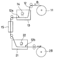
本発明による両面印刷方式記録方法は、例えば、図5に示す装置を用いて実施することができる。
ロール11から矢印Bの方向に巻き戻されて供給される長尺状フィルム基材12は、適当な搬送手段によって第1のインクジェットプリンタ13に案内される。第1のインクジェットプリンタ13内では、プリンタヘッド14から白色インク組成物(又は非白色インク組成物、例えば、カラーインク組成物)が長尺状フィルム基材12の一方の表面12a上に吐出されて、白色ベタ塗り層(又は非白色パターン層)が形成される。湿潤状態の白色ベタ塗り層(又は非白色パターン層)を担持した長尺状フィルム基材12は、適当な搬送手段によって乾燥室15に案内され、乾燥室15で白色ベタ塗り層(又は非白色パターン層)が乾燥される。こうして乾燥された白色ベタ塗り層(又は乾燥非白色パターン層)を一方の表面12a上に担持した長尺状フィルム基材12は、適当な搬送手段によって第2のインクジェットプリンタ21に案内される。第2のインクジェットプリンタ21内では、乾燥白色ベタ塗り層(又は乾燥非白色パターン層)を担持する前記表面12aとは反対側の表面12bに、プリンタヘッド22から非白色インク組成物(又は白色インク組成物)が吐出されて、非白色パターン層(又は白色ベタ塗り層)が形成される。こうして、長尺状フィルム基材12の両側表面上に、白色ベタ塗り層と非白色パターン層とからなる印刷ユニットが連続的に形成される。続いて、適当な搬送手段によって巻取ロール28に輸送され、切断工程を実施するまで長尺状で保存する。なお、巻取ロール28の代わりに、切断手段を設けて各印刷ユニットを含む領域毎に切断することもできる。
The double-sided printing method recording method according to the present invention can be implemented using, for example, the apparatus shown in FIG.
The
本発明においては、第1のインクジェットプリンタによる印刷と第2のインクジェットプリンタによる印刷との間に、乾燥工程を実施する。この乾燥工程は、第1のインクジェットプリンタによって形成される記録層を乾燥させることができる任意の手段を用いることができ、例えば、加熱、風乾、又は放置によって実施することができる。 In the present invention, the drying process is performed between the printing by the first inkjet printer and the printing by the second inkjet printer. This drying step can be performed by any means capable of drying the recording layer formed by the first ink jet printer, and can be carried out, for example, by heating, air drying, or standing.
本発明による両面印刷方式記録方法を実施する場合は、第1のインクジェットプリンタによる記録層と第2のインクジェットプリンタによる記録層とが別々の表面上に設けられるので、第1のインクジェットプリンタによる記録層を担持する長尺状フィルム基材を第2のインクジェットプリンタへ搬送する際に、その記録層が搬送手段によって影響を受けない限り、乾燥工程を実施する必要はない。 When the double-sided printing method recording method according to the present invention is carried out, the recording layer by the first ink jet printer and the recording layer by the second ink jet printer are provided on different surfaces. When the elongate film substrate carrying the film is transported to the second ink jet printer, it is not necessary to perform the drying step unless the recording layer is affected by the transport means.
本発明においては、第1のインクジェットプリンタによって形成される記録層の位置と第2のインクジェットプリンタによって形成される記録層の位置とを正確に調整するために、記録位置確認機構を使用することが好ましい。記録位置確認機構は、長尺状フィルム基材の表面上に設けられた位置マークと、その位置マークを検出する検出センサーと、その検出センサーからの信号に応じて長尺状フィルム基材の印刷位置に第2のインクジェットプリンタのプリンタヘッドからインク滴を吐出させる制御手段とを含む。 In the present invention, a recording position confirmation mechanism may be used to accurately adjust the position of the recording layer formed by the first ink jet printer and the position of the recording layer formed by the second ink jet printer. preferable. The recording position confirmation mechanism includes a position mark provided on the surface of the long film base, a detection sensor for detecting the position mark, and printing of the long film base in accordance with a signal from the detection sensor. Control means for ejecting ink droplets from the printer head of the second ink jet printer at a position.
前記の位置マークは、第1のインクジェットプリンタによって長尺状フィルム基材の表面上に設けることができる。この場合は、第1のインクジェットプリンタによって形成される記録層の位置と関連づけて位置マークを形成することが好ましい。位置マークを第1のインクジェットプリンタによって形成する代わりに、予め位置マークを設けた長尺状フィルム基材を用いることもできる。この場合は、長尺状フィルム基材上の位置マークと関連づけて、第1のインクジェットプリンタによって記録層を形成し、続いて、第2のインクジェットプリンタによって記録層を形成することができる。 The said position mark can be provided on the surface of an elongate film base material with a 1st inkjet printer. In this case, it is preferable to form a position mark in association with the position of the recording layer formed by the first ink jet printer. Instead of forming the position mark with the first ink jet printer, a long film base provided with the position mark in advance can also be used. In this case, the recording layer can be formed by the first ink jet printer in association with the position mark on the long film substrate, and then the recording layer can be formed by the second ink jet printer.
本発明方法は、白地にカラー画像を配置した印刷物(例えば、オフセット印刷物)のリモートプルーフィングで、実際に用紙に印刷を行って校正や確認を行う場合に好適に利用することができる。また、一般的に、白地にカラー画像を配置した印刷物を透明フィルム基材の表面上に設け、非印刷面から観察する印刷方法に広く利用することができる。 The method of the present invention can be suitably used when a printed material (for example, an offset printed material) in which a color image is arranged on a white background is remotely proofed and actually printed on a sheet for calibration and confirmation. In general, a printed matter in which a color image is arranged on a white background is provided on the surface of a transparent film substrate, and can be widely used in a printing method in which observation is performed from a non-printing surface.
以下、実施例によって本発明を具体的に説明するが、これらは本発明の範囲を限定するものではない。 EXAMPLES Hereinafter, the present invention will be specifically described by way of examples, but these do not limit the scope of the present invention.
<実施例1>
出力機として、インクジェットプリンタPX7500〔セイコーエプソン(株)社製〕を2台用意し、それぞれを上下に並べて配置した。上方のインクジェットプリンタをカラー印刷用とし、下方のインクジェットプリンタを白出力用として用いた。上方のインクジェットプリンタには、純正カラーインクカートリッジを装填した。下方のインクジェットプリンタのブラックインク用カートリッジに、白インクカートリッジを挿入した。白インクとしては、特許第3639479号公報の実施例8に記載の白インクを用いた。記録媒体には、ロールに巻回したインクジェット用透明フィルム〔セイコーエプソン(株)製〕を用いた。
まず、上方インクジェットプリンタによって通常のカラー印刷を行い、そのロール先端をそのまま下方インクジェットプリンタに接続し、カラー印刷の記録層が乾燥したことを確認した後に、白インクを出力した。上方インクジェットプリンタでカラー印刷を行う際に、画像の左上に当たる部分に位置確認用パターンの記録を行った。下方インクジェットプリンタにはヘッドキャリッジ部に位置確認センサーを設け、カラー出力の際に記録した位置確認パターンを読み取り、白出力の出力位置を認識した上で、白ベタ出力を行った。
<Example 1>
As an output machine, two inkjet printers PX7500 [manufactured by Seiko Epson Co., Ltd.] were prepared, and they were arranged one above the other. The upper inkjet printer was used for color printing, and the lower inkjet printer was used for white output. The upper inkjet printer was loaded with a genuine color ink cartridge. A white ink cartridge was inserted into the black ink cartridge of the lower inkjet printer. As the white ink, the white ink described in Example 8 of Japanese Patent No. 3639479 was used. As the recording medium, an inkjet transparent film wound by a roll [manufactured by Seiko Epson Corporation] was used.
First, normal color printing was performed by an upper ink jet printer, the roll tip was connected to the lower ink jet printer as it was, and after confirming that the color printing recording layer was dried, white ink was output. When color printing was performed with the upper ink jet printer, a position confirmation pattern was recorded in a portion corresponding to the upper left of the image. The lower ink jet printer is provided with a position confirmation sensor in the head carriage section, reads the position confirmation pattern recorded at the time of color output, recognizes the output position of white output, and then outputs white solid.
本発明方法は、例えば、白地にカラー画像を印刷する様式のパッケージ印刷におけるリモートプルーフィングを、廉価なインクジェット方式により高精度に実現することができる。 According to the method of the present invention, for example, remote proofing in package printing in which a color image is printed on a white background can be realized with high accuracy by an inexpensive inkjet method.
S1,S2,S3・・・長尺状フィルム基材 P1,P2,P3・・・非白色パターン層 W1,W2,W3・・・白色ベタ塗り層 D1,D2,D3・・・印刷ユニット 11・・・ロール 12・・・長尺状フィルム基材 12a,12b・・・長尺状フィルム基材表面 13・・・第1のインクジェットプリンタ 14・・・プリンタヘッド 15・・・乾燥室;21・・・第2のインクジェットプリンタ 22・・・プリンタヘッド 25・・・切断手段 26・・・印刷物;28・・・巻取ロール。
S1, S2, S3 ... long film substrate P1, P2, P3 ... non-white pattern layer W1, W2, W3 ... white solid coating layer D1, D2, D3 ... printing
Claims (8)
前記基材は透明であり、第1の液体吐出手段によって非白色パターン層を設け、その非白色パターン層の乾燥工程の後に、その非白色パターン層の上から、非白色パターン層の全体を覆うように第2の液体吐出手段によって白色ベタ塗り層を設け、
前記白色ベタ塗り層の単位面積当たりのインク吐出量が、前記非白色パターン層の単位面積当たりのインク吐出量よりも多く、
前記白色ベタ塗層は、白色インク組成物として白色顔料を含有する水系インク組成物を用いて設けたものであり、
前記非白色パターン層は、非白色インク組成物として染料または顔料を含有する水系インク組成物を用いて設けたものであり、
前記乾燥工程は、加熱または風乾により行われる、
インクジェット記録方法。 A method of recording a printing unit consisting of a white solid coating layer and a non-white pattern layer on the surface of a long base material that is a resin film by a liquid ejection means,
The substrate is transparent , and a non-white pattern layer is provided by the first liquid ejecting means, and the non-white pattern layer is entirely covered from above the non-white pattern layer after the drying process of the non-white pattern layer. A white solid coating layer is provided by the second liquid discharge means,
The ink discharge amount per unit area of the white solid coating layer is larger than the ink discharge amount per unit area of the non-white pattern layer,
The white solid coating layer is provided using a water-based ink composition containing a white pigment as a white ink composition,
The non-white pattern layer is provided using a water-based ink composition containing a dye or a pigment as the non-white ink composition,
The drying step is performed by heating or air drying.
Inkjet recording method.
Priority Applications (1)
| Application Number | Priority Date | Filing Date | Title |
|---|---|---|---|
| JP2015102521A JP6183408B2 (en) | 2015-05-20 | 2015-05-20 | Inkjet recording method |
Applications Claiming Priority (1)
| Application Number | Priority Date | Filing Date | Title |
|---|---|---|---|
| JP2015102521A JP6183408B2 (en) | 2015-05-20 | 2015-05-20 | Inkjet recording method |
Related Parent Applications (1)
| Application Number | Title | Priority Date | Filing Date |
|---|---|---|---|
| JP2014147462A Division JP5754537B2 (en) | 2014-07-18 | 2014-07-18 | Inkjet recording method |
Publications (2)
| Publication Number | Publication Date |
|---|---|
| JP2015155209A JP2015155209A (en) | 2015-08-27 |
| JP6183408B2 true JP6183408B2 (en) | 2017-08-23 |
Family
ID=54774836
Family Applications (1)
| Application Number | Title | Priority Date | Filing Date |
|---|---|---|---|
| JP2015102521A Active JP6183408B2 (en) | 2015-05-20 | 2015-05-20 | Inkjet recording method |
Country Status (1)
| Country | Link |
|---|---|
| JP (1) | JP6183408B2 (en) |
Families Citing this family (3)
| Publication number | Priority date | Publication date | Assignee | Title |
|---|---|---|---|---|
| JP6786846B2 (en) * | 2016-04-04 | 2020-11-18 | セイコーエプソン株式会社 | Printing method and printing equipment |
| CN110167757B (en) * | 2017-05-19 | 2021-06-29 | 株式会社新克 | Inkjet printer and inkjet printing method using the same |
| JP2019042944A (en) * | 2017-08-30 | 2019-03-22 | 株式会社リコー | Recording method, recording device and method for manufacturing printed matter |
Family Cites Families (16)
| Publication number | Priority date | Publication date | Assignee | Title |
|---|---|---|---|---|
| JP3372681B2 (en) * | 1994-11-28 | 2003-02-04 | キヤノン株式会社 | Inkjet recording method |
| JP2000103995A (en) * | 1998-09-29 | 2000-04-11 | Dainippon Toryo Co Ltd | Ink composition for ink jet printing |
| JP2001171095A (en) * | 1999-12-17 | 2001-06-26 | Sharp Corp | Ink jet print recording method and translucent white ink composition for use therein |
| JP2001246767A (en) * | 2000-03-07 | 2001-09-11 | Sharp Corp | Method and apparatus for forming ink jet image |
| JP2002038063A (en) * | 2000-07-31 | 2002-02-06 | Seiko Epson Corp | Ink set containing white ink and ink jet recording method using the same |
| JP3915554B2 (en) * | 2001-03-14 | 2007-05-16 | セイコーエプソン株式会社 | White ink for inkjet and titanium dioxide slurry used therefor |
| JP2002332433A (en) * | 2001-05-10 | 2002-11-22 | Canon Inc | Liquid composition, inkset, method for forming colored part on medium to be printed and ink-jet printer |
| JP2003145745A (en) * | 2001-11-16 | 2003-05-21 | Konica Corp | Method of inkjet recording and recorder |
| JP2003182061A (en) * | 2001-12-21 | 2003-07-03 | Konica Corp | Inkjet recording method |
| JP2003220698A (en) * | 2002-01-29 | 2003-08-05 | Konica Corp | Ink jet recording method, apparatus thereof and recording unit |
| JP4300745B2 (en) * | 2002-04-10 | 2009-07-22 | コニカミノルタホールディングス株式会社 | White ink composition for inkjet and image forming method |
| JP2004018546A (en) * | 2002-06-12 | 2004-01-22 | Konica Minolta Holdings Inc | Ink set for inkjet and inkjet image-forming method |
| JP4556444B2 (en) * | 2003-03-27 | 2010-10-06 | コニカミノルタホールディングス株式会社 | Image recording device |
| JP2007154016A (en) * | 2005-12-05 | 2007-06-21 | Konica Minolta Holdings Inc | Ink set for inkjet and inkjet recording method |
| JP5315645B2 (en) * | 2007-08-30 | 2013-10-16 | セイコーエプソン株式会社 | Inkjet recording method for recording pattern layer and white solid coating layer on long sheet |
| JP5754537B2 (en) * | 2014-07-18 | 2015-07-29 | セイコーエプソン株式会社 | Inkjet recording method |
-
2015
- 2015-05-20 JP JP2015102521A patent/JP6183408B2/en active Active
Also Published As
| Publication number | Publication date |
|---|---|
| JP2015155209A (en) | 2015-08-27 |
Similar Documents
| Publication | Publication Date | Title |
|---|---|---|
| JP5315645B2 (en) | Inkjet recording method for recording pattern layer and white solid coating layer on long sheet | |
| JP2008200850A (en) | Inkjet recording method for recording patterned layer and white solid coating layer | |
| JP5655357B2 (en) | Printing apparatus and printing method | |
| JP5754537B2 (en) | Inkjet recording method | |
| JP2013010364A (en) | Inkjet recording method for recording pattern layer and white solid coating layer on long sheet | |
| JP4882248B2 (en) | Ink jet ink and ink jet recording method | |
| JP6183408B2 (en) | Inkjet recording method | |
| JP2008200851A (en) | Inkjet recording method for recording patterned layer and white solid coating layer | |
| JP2010023498A (en) | Inkjet recorder and drying condition determination method of recorded image | |
| JP2008200853A (en) | Inkjet recording method for recording patterned layer and white solid coating layer | |
| JP2012153149A (en) | Inkjet recording method for recording pattern layer and white solid coat layer on long sheet | |
| US8668309B2 (en) | Fluid ejecting apparatus and fluid ejecting method | |
| JP5655457B2 (en) | Printing apparatus and printing method | |
| JP2008200852A (en) | Inkjet recording method for recording patterned layer and white solid coating layer | |
| JP2008200854A (en) | Inkjet recording method for recording patterned layer and white solid coating layer | |
| JPH1158930A (en) | Forming method of ink jet receptor layer and material to be recorded | |
| JP5621366B2 (en) | Printing apparatus and program | |
| JP2006110930A (en) | Inkjet recording method and inkjet printer for use in it | |
| JP2003096341A (en) | Recording liquid for ink jet recording system, recording method, record image, and discrimination method for recording liquid | |
| JP2003251795A (en) | Ink jet recording method, ink jet recording formed by that method, and ink jet recorder implementing that method | |
| JP2020029006A (en) | Recording medium | |
| JPH04211984A (en) | Ink jet recording method | |
| JP2012011702A (en) | Apparatus and method for ejecting fluid | |
| JP2006272730A (en) | Inkjet recording method | |
| JP2000296665A (en) | Recording medium for ink jet recorder and method for ink jet recording using the recording medium |
Legal Events
| Date | Code | Title | Description |
|---|---|---|---|
| A521 | Request for written amendment filed |
Free format text: JAPANESE INTERMEDIATE CODE: A523 Effective date: 20150616 |
|
| A621 | Written request for application examination |
Free format text: JAPANESE INTERMEDIATE CODE: A621 Effective date: 20150616 |
|
| A977 | Report on retrieval |
Free format text: JAPANESE INTERMEDIATE CODE: A971007 Effective date: 20160120 |
|
| A131 | Notification of reasons for refusal |
Free format text: JAPANESE INTERMEDIATE CODE: A131 Effective date: 20160126 |
|
| A521 | Request for written amendment filed |
Free format text: JAPANESE INTERMEDIATE CODE: A523 Effective date: 20160323 |
|
| A131 | Notification of reasons for refusal |
Free format text: JAPANESE INTERMEDIATE CODE: A131 Effective date: 20160621 |
|
| A521 | Request for written amendment filed |
Free format text: JAPANESE INTERMEDIATE CODE: A523 Effective date: 20160812 |
|
| A131 | Notification of reasons for refusal |
Free format text: JAPANESE INTERMEDIATE CODE: A131 Effective date: 20170117 |
|
| A521 | Request for written amendment filed |
Free format text: JAPANESE INTERMEDIATE CODE: A523 Effective date: 20170315 |
|
| TRDD | Decision of grant or rejection written | ||
| A01 | Written decision to grant a patent or to grant a registration (utility model) |
Free format text: JAPANESE INTERMEDIATE CODE: A01 Effective date: 20170627 |
|
| A61 | First payment of annual fees (during grant procedure) |
Free format text: JAPANESE INTERMEDIATE CODE: A61 Effective date: 20170710 |
|
| R150 | Certificate of patent or registration of utility model |
Ref document number: 6183408 Country of ref document: JP Free format text: JAPANESE INTERMEDIATE CODE: R150 |