JP2012011702A - Apparatus and method for ejecting fluid - Google Patents
Apparatus and method for ejecting fluid Download PDFInfo
- Publication number
- JP2012011702A JP2012011702A JP2010151331A JP2010151331A JP2012011702A JP 2012011702 A JP2012011702 A JP 2012011702A JP 2010151331 A JP2010151331 A JP 2010151331A JP 2010151331 A JP2010151331 A JP 2010151331A JP 2012011702 A JP2012011702 A JP 2012011702A
- Authority
- JP
- Japan
- Prior art keywords
- image
- nozzle
- medium
- fluid
- printed
- Prior art date
- Legal status (The legal status is an assumption and is not a legal conclusion. Google has not performed a legal analysis and makes no representation as to the accuracy of the status listed.)
- Withdrawn
Links
Images


Abstract
Description
本発明は、流体噴射装置、及び、流体噴射方法に関する。 The present invention relates to a fluid ejecting apparatus and a fluid ejecting method.
流体噴射装置の一つとして、媒体に対してインク(流体)を噴射するノズルが所定方向に並んだノズル列を備えるインクジェットプリンター(以下、プリンター)が挙げられる。プリンターとして、ノズル列を所定方向と交差する移動方向に移動させながらノズルからインクを噴射させる画像形成動作と、ノズル列に対して媒体を所定方向である搬送方向に搬送する搬送動作を繰り返すプリンターが知られている。
プリンターの中には、主画像と背景画像を重ねて印刷するために、背景画像を印刷する2つのノズル列が移動方向に並び、その背景画像を印刷する2つのノズル列の間に主画像を印刷するノズル列を配置したプリンターがある(例えば、特許文献1を参照)。
As one of the fluid ejecting apparatuses, there is an ink jet printer (hereinafter referred to as a printer) including a nozzle row in which nozzles that eject ink (fluid) to a medium are arranged in a predetermined direction. As a printer, there is a printer that repeats an image forming operation for ejecting ink from a nozzle while moving a nozzle row in a moving direction intersecting a predetermined direction, and a transport operation for transporting a medium to the nozzle row in a transport direction that is a predetermined direction. Are known.
In the printer, in order to print the main image and the background image on top of each other, two nozzle arrays that print the background image are arranged in the movement direction, and the main image is displayed between the two nozzle arrays that print the background image. There is a printer in which nozzle rows to be printed are arranged (see, for example, Patent Document 1).
ただし、上述のプリンターでは、例えば、背景画像が印刷された直ぐ後に主画像が印刷される。そのため、背景画像の乾燥時間を十分に確保できず、画像が滲んだり混色したりしてしまう。その結果、印刷画像の画質が劣化してしまう。
そこで、本発明では、画像の画質劣化を抑制することを目的とする。
However, in the above-described printer, for example, the main image is printed immediately after the background image is printed. For this reason, a sufficient drying time for the background image cannot be ensured, and the image is blurred or mixed. As a result, the image quality of the printed image is degraded.
Accordingly, an object of the present invention is to suppress image quality deterioration of an image.
前記課題を解決する為の主たる発明は、(A)第1の流体を噴射するノズルが所定方向に並ぶ第1ノズル列と、(B)第2の流体を噴射するノズルが前記所定方向に並び、且つ、前記所定方向と交差する方向である移動方向に前記第1ノズル列と並ぶ第2ノズル列と、(C)前記第1の流体による主画像の形成と、前記第2の流体による背景画像の形成とを、媒体に重ねて行う場合に、前記第1ノズル列及び前記第2ノズル列と前記媒体とを前記移動方向の一方の方向に相対移動させる往路動作と、前記第1ノズル列及び前記第2ノズル列と前記媒体とを前記移動方向の他方の方向に相対移動させる復路動作と、前記第1ノズル列及び前記第2ノズル列に対する前記媒体の相対位置を前記所定方向の一方側に移動させる搬送動作とを、前記往路動作、前記復路動作、前記搬送動作の順に繰り返すことによって、前記媒体に画像を形成させ、前記主画像を形成する前記第1ノズル列の一部のノズル群と前記背景画像を形成する前記第2ノズル列の一部のノズル群のうちの一方のノズル群であり、他方のノズル群よりも前記所定方向の他方側に位置する前記一方のノズル群を用いて、前記他方のノズル群よりも先に、前記媒体の所定領域に対して画像を形成させ、前記主画像の形成のために、前記往路動作と前記復路動作のうちの少なくとも一方の動作時に前記ノズルから流体を噴射させ、前記背景画像の形成のために、前記往路動作と前記復路動作のうちの少なくとも一方の動作時に前記ノズルから流体を噴射させる制御部と、(D)を有することを特徴とする流体噴射装置である。
本発明の他の特徴は、本明細書、及び添付図面の記載により、明らかにする。
The main invention for solving the above problems is that (A) a first nozzle row in which nozzles for ejecting a first fluid are arranged in a predetermined direction, and (B) nozzles for injecting a second fluid are arranged in the predetermined direction. And a second nozzle row aligned with the first nozzle row in a moving direction that is a direction intersecting the predetermined direction, (C) formation of a main image by the first fluid, and background by the second fluid When the image formation is performed on the medium, the forward movement operation of relatively moving the first nozzle row, the second nozzle row, and the medium in one of the movement directions; and the first nozzle row And a return path operation for relatively moving the second nozzle row and the medium in the other direction of the moving direction, and a relative position of the medium with respect to the first nozzle row and the second nozzle row on one side in the predetermined direction. The transfer operation to be moved to By repeating the operation, the return path operation, and the transport operation in this order, an image is formed on the medium, and a part of the nozzle group of the first nozzle row that forms the main image and the second image that forms the background image One nozzle group of a part of the nozzle groups of the nozzle row, and using the one nozzle group located on the other side in the predetermined direction with respect to the other nozzle group, precedes the other nozzle group. An image is formed on a predetermined area of the medium, and a fluid is ejected from the nozzle during at least one of the forward operation and the backward operation to form the main image, and the background image In order to form the fluid ejecting apparatus, the fluid ejecting apparatus includes: (D) a control unit that ejects fluid from the nozzle during at least one of the forward path operation and the backward path operation.
Other features of the present invention will become apparent from the description of this specification and the accompanying drawings.
===開示の概要===
本明細書の記載、及び添付図面の記載により、少なくとも次のことが明らかとなる。
=== Summary of disclosure ===
At least the following will become apparent from the description of the present specification and the accompanying drawings.
即ち、(A)第1の流体を噴射するノズルが所定方向に並ぶ第1ノズル列と、(B)第2の流体を噴射するノズルが前記所定方向に並び、且つ、前記所定方向と交差する方向である移動方向に前記第1ノズル列と並ぶ第2ノズル列と、(C)前記第1の流体による主画像の形成と、前記第2の流体による背景画像の形成とを、媒体に重ねて行う場合に、前記第1ノズル列及び前記第2ノズル列と前記媒体とを前記移動方向の一方の方向に相対移動させる往路動作と、前記第1ノズル列及び前記第2ノズル列と前記媒体とを前記移動方向の他方の方向に相対移動させる復路動作と、前記第1ノズル列及び前記第2ノズル列に対する前記媒体の相対位置を前記所定方向の一方側に移動させる搬送動作とを、前記往路動作、前記復路動作、前記搬送動作の順に繰り返すことによって、前記媒体に画像を形成させ、前記主画像を形成する前記第1ノズル列の一部のノズル群と前記背景画像を形成する前記第2ノズル列の一部のノズル群のうちの一方のノズル群であり、他方のノズル群よりも前記所定方向の他方側に位置する前記一方のノズル群を用いて、前記他方のノズル群よりも先に、前記媒体の所定領域に対して画像を形成させ、前記主画像の形成のために、前記往路動作と前記復路動作のうちの少なくとも一方の動作時に前記ノズルから流体を噴射させ、前記背景画像の形成のために、前記往路動作と前記復路動作のうちの少なくとも一方の動作時に前記ノズルから流体を噴射させる制御部と、(D)を有することを特徴とする流体噴射装置である。
このような流体噴射装置によれば、主画像と背景画像のうちの下層画像の乾燥時間を長くすることができ、画像の滲み等を抑制することができる。その結果、画像の画質劣化を抑制できる。
That is, (A) a first nozzle row in which nozzles for ejecting a first fluid are arranged in a predetermined direction, and (B) nozzles for injecting a second fluid are arranged in the predetermined direction and intersect the predetermined direction. A second nozzle row aligned with the first nozzle row in a moving direction, which is a direction, and (C) formation of a main image by the first fluid and formation of a background image by the second fluid are superimposed on the medium. The first nozzle row, the second nozzle row, and the medium, and the medium is moved forward in one direction of the movement direction, and the first nozzle row, the second nozzle row, and the medium. And a transporting operation for moving the relative position of the medium to the one side in the predetermined direction with respect to the first nozzle row and the second nozzle row, Outward movement, the backward movement, the conveyance By repeating the order of operation, an image is formed on the medium, and a part of the nozzle group of the first nozzle array that forms the main image and a part of the nozzle group of the second nozzle array that forms the background image One nozzle group, and using the one nozzle group located on the other side in the predetermined direction with respect to the other nozzle group, the first nozzle group is placed in a predetermined area of the medium before the other nozzle group. In order to form the main image, in order to form the main image, fluid is ejected from the nozzle during at least one of the forward operation and the backward operation, and the forward image is formed to form the background image. A fluid ejecting apparatus comprising: (D) a control unit that ejects fluid from the nozzle during at least one of an operation and a return path operation.
According to such a fluid ejecting apparatus, it is possible to lengthen the drying time of the lower layer image of the main image and the background image, and to suppress bleeding of the image. As a result, image quality deterioration of the image can be suppressed.
かかる流体噴射装置であって、前記媒体の所定領域に対して先に画像形成を行う前記一方のノズル群は、少なくとも前記往路動作時に流体を噴射すること。
このような流体噴射装置によれば、復路動作を下層画像の乾燥時間に充てることができ、下層画像の乾燥時間を長くすることができる。
In the fluid ejecting apparatus, the one nozzle group that performs image formation on a predetermined area of the medium ejects fluid at least during the forward operation.
According to such a fluid ejecting apparatus, the return path operation can be used for the drying time of the lower layer image, and the drying time of the lower layer image can be lengthened.
かかる流体噴射装置であって、前記媒体の所定領域に対して後に画像形成を行う前記他方のノズル群は、少なくとも前記復路動作時に流体を噴射すること。
このような流体噴射装置によれば、往路動作を下層画像の乾燥時間に充てることができ、下層画像の乾燥時間を長くすることができる。
In this fluid ejecting apparatus, the other nozzle group that will later form an image on a predetermined area of the medium ejects fluid at least during the return path operation.
According to such a fluid ejecting apparatus, the forward movement operation can be used for the drying time of the lower layer image, and the drying time of the lower layer image can be lengthened.
かかる流体噴射装置であって、1回の前記往路動作に要する時間と1回の前記復路動作に要する時間のうちの少なくとも一方は、1回の前記搬送動作に要する時間よりも長いこと。
このような流体噴射装置によれば、往路動作または復路動作に要する時間が下層画像の乾燥時間となる場合に、下層画像の乾燥時間がより長くなる。
In this fluid ejecting apparatus, at least one of the time required for one forward operation and the time required for one return operation is longer than the time required for one transport operation.
According to such a fluid ejecting apparatus, when the time required for the forward path operation or the backward path operation becomes the drying time of the lower layer image, the drying time of the lower layer image becomes longer.
かかる流体噴射装置であって、前記背景画像を形成する前記第2ノズル列の一部のノズル群と前記所定方向の位置が同じである前記第1ノズル列の前記ノズルも使用して、前記背景画像を形成すること。
このような流体噴射装置によれば、所望の背景画像を形成することができる。
In this fluid ejecting apparatus, the background is also used by using the nozzles in the first nozzle row that have the same position in the predetermined direction as the nozzle group that is part of the second nozzle row that forms the background image. Forming an image.
According to such a fluid ejecting apparatus, a desired background image can be formed.
また、第1の流体を噴射するノズルが所定方向に並ぶ第1ノズル列と、第2の流体を噴射するノズルが前記所定方向に並び、且つ、前記所定方向と交差する方向である移動方向に前記第1ノズル列と並ぶ第2ノズル列と、を有する流体噴射装置の流体噴射方法であって、前記第1の流体による主画像の形成と、前記第2の流体による背景画像の形成とを、媒体に重ねて行う場合に、前記第1ノズル列及び前記第2ノズル列と前記媒体とを前記移動方向の一方の方向に相対移動させる往路動作と、前記第1ノズル列及び前記第2ノズル列と前記媒体とを前記移動方向の他方の方向に相対移動させる復路動作と、前記第1ノズル列及び前記第2ノズル列に対する前記媒体の相対位置を前記所定方向の一方側に移動させる搬送動作とを、前記往路動作、前記復路動作、前記搬送動作の順に繰り返すことによって、前記媒体に画像を形成し、前記主画像を形成する前記第1ノズル列の一部のノズル群と前記背景画像を形成する前記第2ノズル列の一部のノズル群のうちの一方のノズル群であり、他方のノズル群よりも前記所定方向の他方側に位置する前記一方のノズル群を用いて、前記他方のノズル群よりも先に、前記媒体の所定領域に対して画像を形成し、前記主画像の形成のために、前記往路動作と前記復路動作のうちの少なくとも一方の動作時に前記ノズルから流体を噴射し、前記背景画像の形成のために、前記往路動作と前記復路動作のうちの少なくとも一方の動作時に前記ノズルから流体を噴射する、ことを特徴とする流体噴射方法である。
このような流体噴射方法によれば、主画像と背景画像のうちの下層画像の乾燥時間を長くすることができ、画像の滲み等を抑制することができ、画像の画質劣化を抑制できる。
In addition, a first nozzle row in which nozzles for ejecting the first fluid are arranged in a predetermined direction, and a nozzle in which the second fluid is ejected are arranged in the predetermined direction and in a moving direction that is a direction intersecting the predetermined direction. A fluid ejecting method for a fluid ejecting apparatus having a second nozzle array aligned with the first nozzle array, wherein a main image is formed by the first fluid and a background image is formed by the second fluid. A forward operation for relatively moving the first nozzle row, the second nozzle row, and the medium in one direction of the movement direction, and the first nozzle row and the second nozzle, A return path operation in which the row and the medium are relatively moved in the other direction of the movement direction, and a transport operation in which the relative position of the medium with respect to the first nozzle row and the second nozzle row is moved to one side in the predetermined direction. And the forward movement The second nozzle that forms the background image and the partial nozzle group of the first nozzle row that forms an image on the medium by repeating the return path operation and the transport operation in this order. One nozzle group of a part of the nozzle groups in the row, and using the one nozzle group located on the other side in the predetermined direction with respect to the other nozzle group, before the other nozzle group Forming an image on a predetermined area of the medium, and ejecting fluid from the nozzle during at least one of the forward operation and the backward operation for forming the main image, In order to form the fluid, the fluid is ejected from the nozzle during at least one of the forward operation and the backward operation.
According to such a fluid ejection method, it is possible to lengthen the drying time of the lower layer image of the main image and the background image, it is possible to suppress bleeding of the image and the like, and it is possible to suppress image quality deterioration of the image.
===印刷システムについて===
以下、インクジェットプリンター(以下、プリンター)とコンピューターが接続された印刷システムを例に挙げて実施形態を説明する。
=== About the printing system ===
Hereinafter, an embodiment will be described by taking as an example a printing system in which an inkjet printer (hereinafter referred to as a printer) and a computer are connected.
図1は、プリンター1の全体構成ブロック図である。図2は、プリンター1の斜視図である。コンピューター60は、プリンター1と通信可能に接続されており、プリンター1に画像を印刷させるための印刷データをプリンター1に出力する。なお、コンピューター60には、アプリケーションプログラムから出力された画像データを印刷データに変換するためのプログラム(プリンタードライバー)がインストールされている。プリンタードライバーは、CD−ROMなどの記録媒体(コンピューターが読み取り可能な記録媒体)に記録されていたり、インターネットを介してコンピューターにダウンロード可能であったりする。
FIG. 1 is a block diagram of the overall configuration of the
コントローラー10は、プリンター1の制御を行うための制御ユニットである。インターフェース部11はコンピューター60とプリンター1との間でデータの送受信を行うためのものである。CPU12はプリンター1全体の制御を行うための演算処理装置である。メモリー13はCPU12のプログラムを格納する領域や作業領域等を確保するためのものである。CPU12はユニット制御回路14により各ユニットを制御する。なお、プリンター1内の状況を検出器群50が監視し、その検出結果に基づいて、コントローラー10は各ユニットを制御する。
The
搬送ユニット20は、媒体Sを印刷可能な位置に送り込み、印刷時には搬送方向に所定の搬送量で媒体Sを搬送させるものである。
キャリッジユニット30は、ヘッド41を搬送方向と交差する移動方向に移動させるためのものであり、キャリッジ31を有する。
The
The
ヘッドユニット40は、媒体Sにインクを噴射するためのものであり、ヘッド41を有する。ヘッド41はキャリッジ31によって移動方向に移動する。ヘッド41の下面には、インク噴射部であるノズルが複数設けられ、各ノズルには、インクが入った圧力室(不図示)が設けられている。
The
図3は、ヘッド41の下面に設けられるノズルの配列を示す図である。なお、図はヘッド41の上面から仮想的にノズルを見た図である。ヘッド41の下面には、180個のノズルが搬送方向に所定の間隔Dで並んだノズル列が5列形成されている。図示するように、ブラックインクを噴射するブラックノズル列K・シアンインクを噴射するシアンノズル列C・マゼンタインクを噴射するマゼンタノズル列M・イエローインクを噴射するイエローノズル列Y・白インクを噴射するホワイトノズル列Wが、移動方向に並んでいる。なお、各ノズル列が有する180個のノズルに対して、搬送方向の下流側のノズルから順に小さい番号を付す(#1〜#180)。
FIG. 3 is a diagram illustrating an arrangement of nozzles provided on the lower surface of the
このようなプリンター1では、移動方向に沿って移動するヘッド41からインク滴を断続的に噴射させて媒体上にドットを形成する画像形成動作と、ヘッド41に対して媒体を搬送方向に搬送する搬送動作とが繰り返される。そうすることで、先の画像形成動作により形成されたドットの位置とは異なる媒体上の位置に、後の画像形成動作にてドットを形成することができ、媒体上に2次元の画像を印刷することができる。
In such a
===印刷モードについて===
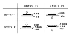
図4は、本実施形態のプリンター1が有する印刷モードを説明する図である。プリンター1は、4色のインク(YMCK)によって印刷する主画像(カラー画像やモノクロ画像)だけを媒体上に印刷する「カラーモード」と、白インクによる白色の背景画像と主画像を重ねて媒体上に印刷する「白使用モード」のうちの、何れか一方のモードにて媒体上に画像を印刷する。白使用モードのように主画像の背景に白色の背景画像を設けることで、特に媒体が白色でない場合に、発色性の良い画像を印刷することができる。また、媒体が透明である場合には、主画像と背景画像を重ねて印刷することで、印刷物の反対側が透けてしまうことを防止できる。
=== About print mode ===
FIG. 4 is a diagram illustrating a printing mode that the
更に、プリンター1は、表刷りモードと裏刷りモードのうちの何れか一方のモードにて媒体上に画像を印刷する。表刷りモードは、主画像が印刷面側から視認されるように画像を印刷するモードであり、裏刷りモードは、媒体を介して主画像が印刷面と反対側の面から視認されるように画像を印刷するモードである。よって、媒体が透明性を有する場合に、裏刷りモードが実施される。カラーモードでは媒体上に主画像だけが印刷されるため、表刷りモードであっても裏刷りモードであっても、媒体上に直に主画像が印刷される。一方、白使用モードでは主画像と背景画像が重ねて印刷されるため、表刷りモードでは媒体の所定領域に対して先に背景画像が印刷され、その背景画像上に主画像が印刷される。逆に、裏刷りモードでは媒体の所定領域に対して先に主画像が印刷され、その主画像上に背景画像が印刷される。
Further, the
このように、プリンター1は、表刷り・カラーモードと、裏刷り・カラーモードと、表刷り・白使用モードと、裏刷り・白使用モードの4通りの印刷モードを有する。
As described above, the
なお、本明細書における「白色」とは、可視光線のすべての波長を100%反射する物体の表面色である厳密な意味での白色に限らず、所謂「白っぽい色」のように社会通念上、白色と呼ばれる色を含むものとする。「白色」とは、例えば、(1)x-rite社製の測色機eye-oneProを用いて、測色モード:スポット測色、光源:D50、バッキング:Black、印刷媒体:透明フィルムで測色した場合に、L*a*b*色空間での標記がa*b*平面上で半径20の円周及びその内側にあり、且つ、L*値が70以上で表される色相範囲内の色か、(2)ミノルタ製測色計CM2022を用いて測定モードD502°視野、SCFモード、白地バックで測色した場合に、L*a*b*色空間での標記がa*b*平面上で半径20の円周及びその内側にあり、且つ、L*値が70以上で表される色相範囲内の色か、(3)特開2004−306591号公報に記載されているように画像の背景として用いられるインクの色か、をいい、背景として用いられるのであれば純粋な白に限られない。
The term “white” in this specification is not limited to white in the strict sense that is the surface color of an object that reflects 100% of all wavelengths of visible light, but is commonly known as “white”. , Including a color called white. “White” means, for example, (1) color measurement mode: spot color measurement, light source: D50, backing: Black, printing medium: transparent film using x-rite colorimeter eye-onePro When colored, the mark in the L * a * b * color space is on the a * b * plane and within the circumference of the
また、白インクのみを使用して背景画像を印刷すると、その白インクの色そのものの色が背景画像の色となる。しかし、同じように白インクと呼ばれるインクであっても、インクの材料などによって白色の色味が若干異なる。そのため、使用する白インクによってユーザーが所望する色とは異なる色の背景画像が印刷されてしまう場合がある。また、単純な白色ではなく、若干の有彩色を有する背景画像が所望されることもある。そこで、本実施形態のプリンター1は、白インクと共に少量の4色インク(YMCK)を適宜使用して、所望の白色の背景画像(調整された白色の背景画像)を印刷する。そうすることで、逆に、白インクが若干の色彩を有する場合、その色彩を打ち消すインクと共に背景画像を印刷し、背景画像を無彩色に近づけることもできる。
When a background image is printed using only white ink, the color of the white ink itself becomes the color of the background image. However, even in the case of ink called white ink, the color of white is slightly different depending on the ink material. Therefore, a background image having a color different from the color desired by the user may be printed depending on the white ink used. In addition, a background image having a slight chromatic color instead of simple white may be desired. Accordingly, the
所望の白色の背景画像をプリンター1に印刷させるための印刷データは、プリンター1が予め記憶するようにしても良いし、プリンタードライバーが作成するようにしても良い。プリンター1のモニターやコンピューターの画面をユーザーが見るなどして、所望の背景画像の色の選択が行われる場合には、選択された色に応じた背景画像の印刷データをプリンタードライバーが生成するようにするとよい。
Print data for causing the
===印刷方法===
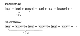
図5は、本実施形態のプリンター1が実施する印刷方法を説明する図である。プリンター1は、「第1印刷方法」と「第2印刷方法」のうちの何れか一方の印刷方法にて媒体上に画像を印刷する。以下では、ヘッド41に対して媒体が搬送方向下流側に搬送される動作を「搬送動作」と呼び、ヘッド41が移動方向に移動する動作を「パス」と呼ぶ。また、ヘッド41が媒体に対して移動方向の一方の方向へ移動する動作(例えば右側から左側へ移動する動作)を「往路動作」と呼び、ヘッド41が媒体に対して移動方向の他方の方向へ移動する動作(例えば左側から右側へ移動する動作)を「復路動作」と呼ぶ。即ち、往路動作と復路動作は、移動方向の双方向におけるヘッド41(ノズル列)と媒体との相対移動である。なお、往路動作は、図2に示すホームポジションHPからキャリッジ31が離れる動作をいい、復路動作は、キャリッジ31がホームポジションHPに近付く動作をいう。
=== Printing method ===
FIG. 5 is a diagram illustrating a printing method performed by the
図5に示すように、第1印刷方法では、往路動作、復路動作、搬送動作が順に繰り返される。一方、第2印刷方法では、往路動作、搬送動作、復路動作、搬送動作が順に繰り返される。即ち、第2印刷方法では往路動作と復路動作の間に搬送動作が実施されるのに対して、第1印刷方法では往路動作と復路動作の間に搬送動作が実施されない。よって、第2印刷方法では、往路動作でも復路動作でも画像が印刷される。一方、第1印刷方法では、往路動作と復路動作のうちの少なくとも一方で画像が印刷される。即ち、第1印刷方法では、図4に示す主画像を形成するために、往路動作と復路動作のうちの少なくとも一方の動作時に、4色インクのノズル列(YMCK)からインクが噴射され、背景画像を形成するために、往路動作と復路動作のうちの少なくとも一方の動作時に、ホワイトノズル列W、及び、4色インクのノズル列からインクが噴射される。 As shown in FIG. 5, in the first printing method, the forward movement operation, the backward movement operation, and the conveyance operation are repeated in order. On the other hand, in the second printing method, the forward movement operation, the conveyance operation, the backward movement operation, and the conveyance operation are repeated in order. That is, in the second printing method, the transport operation is performed between the forward path operation and the backward path operation, whereas in the first printing method, the transport operation is not performed between the forward path operation and the backward path operation. Therefore, in the second printing method, an image is printed both in the forward path operation and in the backward path operation. On the other hand, in the first printing method, an image is printed in at least one of the forward path operation and the backward path operation. That is, in the first printing method, in order to form the main image shown in FIG. 4, ink is ejected from the nozzle row (YMCK) of four colors ink at the time of at least one of the forward operation and the backward operation. In order to form an image, ink is ejected from the white nozzle row W and the four-color ink nozzle row during at least one of the forward pass operation and the return pass operation.
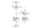
図6は、印刷方法の設定フローを示す図である。プリンタードライバーは、ユーザーから印刷指令を受け取ると、コンピューター60のディスプレイにウィンドウを表示する等して、ユーザーに「白使用モード」と「カラーモード」の何れか一方の印刷モードを選択させる。その後、プリンタードライバーは、ユーザーによって白使用モードが選択されたのか否かを判断する(S01)。白使用モードが選択された場合(S01→Y)、プリンタードライバーは、印刷指令を受け取った画像の印刷方法を第1印刷方法に設定する(S02)。
FIG. 6 is a diagram illustrating a setting flow of the printing method. When the printer driver receives a print command from the user, the printer driver displays a window on the display of the
これに対して、カラーモードが選択された場合(S01→N)、プリンタードライバーは、ユーザーに「第1印刷方法」と「第2印刷方法」の何れか一方の印刷方法を選択させる(S03)。ユーザーによって第1印刷方法が選択された場合(S03→N)、プリンタードライバーは、印刷指令を受け取った画像の印刷方法を第1印刷方法に設定する(S02)。一方、ユーザーによって第2印刷方法が選択された場合(S03→Y)、プリンタードライバーは、印刷指令を受け取った画像の印刷方法を第2印刷方法に設定する(S04)。 On the other hand, when the color mode is selected (S01 → N), the printer driver causes the user to select one of the “first printing method” and the “second printing method” (S03). . When the first printing method is selected by the user (S03 → N), the printer driver sets the printing method of the image that has received the print command to the first printing method (S02). On the other hand, when the second printing method is selected by the user (S03 → Y), the printer driver sets the printing method of the image that has received the print command to the second printing method (S04).
その後、プリンタードライバーは、印刷モードに応じて印刷データを作成する。例えば、カラーモードが設定されている場合、プリンタードライバーは主画像用の印刷データだけを作成し、白使用モードが設定されている場合、プリンタードライバーは主画像用の印刷データだけでなく背景画像用の印刷データも作成する。また、プリンタードライバーは、作成した印刷データを、印刷モードや印刷方法に応じて、プリンター1に転送する順に並べ替える。例えば、表刷り・白使用モードが設定されている場合、プリンタードライバーは、媒体の所定領域に対して主画像よりも背景画像が先に印刷されるように、各画像の印刷データを並べ替える。また、第1印刷方法が設定されている場合、プリンタードライバーは往路動作と復路動作のうちの少なくとも一方の動作時に画像が印刷されるように各画像の印刷データを並べ替える。一方、第2印刷方法が設定されている場合、プリンタードライバーは往路動作でも復路動作でも画像が印刷されるように各画像の印刷データを並べ替える。
Thereafter, the printer driver creates print data according to the print mode. For example, when the color mode is set, the printer driver creates only the print data for the main image, and when the white usage mode is set, the printer driver uses the background image as well as the print data for the main image. Print data is also created. Further, the printer driver rearranges the created print data in the order of transfer to the
また、プリンタードライバーは、作成した印刷データと共に、第1印刷方法と第2印刷方法のうちの何れの印刷方法を実施するのかを示すデータを、プリンター1に送信する。プリンター1(コントローラー10)は、第1印刷方法を実施するデータを受信した場合には、往路動作、復路動作、搬送動作を順に繰り返し、第2印刷方法を実施するデータを受信した場合には、往路動作、搬送動作、復路動作、搬送動作を順に繰り返す。
Further, the printer driver transmits to the
なお、本実施形態では、ユーザーに白使用モードとカラーモードの何れかを選択させるとしているが、これに限らない。例えば、印刷媒体が透明性の有る媒体である場合にはプリンタードライバーが白使用モードを選択し、印刷媒体がそれ以外の媒体である場合にはプリンタードライバーがカラーモードを選択するようにしてもよい。 In the present embodiment, the user is allowed to select either the white use mode or the color mode, but the present invention is not limited to this. For example, when the print medium is a transparent medium, the printer driver may select the white use mode, and when the print medium is any other medium, the printer driver may select the color mode. .
また、図6のフローでは、カラーモードの場合に、ユーザーに第1印刷方法と第2印刷方法の何れかを選択させているが、これに限らない。第1印刷方法において往路動作と復路動作の一方だけで画像を印刷するようにすれば、往路と復路の特性差が排除され、より高画質な画像を印刷することができる。一方で、第1印刷方法に比べて第2印刷方法の方が画像を早く印刷することができる。そこで、プリンター1の基本設定で「きれいモード」が設定されている場合、プリンタードライバーは印刷方法を第1印刷方法に設定し、「はやいモード」が設定されている場合には、プリンタードライバーは印刷方法を第2印刷方法に設定するようにしてもよい。
In the flow of FIG. 6, in the color mode, the user selects either the first printing method or the second printing method. However, the present invention is not limited to this. If the image is printed by only one of the forward path operation and the backward path operation in the first printing method, the characteristic difference between the forward path and the backward path is eliminated, and a higher quality image can be printed. On the other hand, the second printing method can print an image faster than the first printing method. Therefore, when “Premium mode” is set in the basic settings of the
<実施例1>
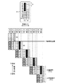
図7は、実施例1の印刷方法を説明する図である。以下、ユーザーによって白使用モードが選択され、プリンタードライバーが印刷方法を第1印刷方法に設定した場合について説明する。図7は、表刷り・白使用モードの印刷を示す。また、説明の簡略のため、4色インクを各々噴射するノズル列(YMCK)をまとめて「カラーノズル列Co(第1ノズル列に相当)」と呼ぶ。図では、カラーノズル列Co及びホワイトノズル列W(第2ノズル列に相当)にそれぞれ属するノズル数を10個(#1〜#10)とし、ノズル列において搬送方向に並ぶノズルの間隔をDとする。カラーノズル列Coに属するノズルを丸で示し、ホワイトノズル列Wに属するノズルを三角で示す。また、実際のプリンター1ではヘッド41に対して媒体が搬送方向下流側に搬送されるが、図7の下図ではヘッド41が搬送方向上流側に搬送される様子を示す。
<Example 1>
FIG. 7 is a diagram illustrating a printing method according to the first embodiment. Hereinafter, a case where the white use mode is selected by the user and the printer driver sets the printing method to the first printing method will be described. FIG. 7 shows printing in the front printing / white use mode. For the sake of simplicity, the nozzle rows (YMCK) for ejecting the four color inks are collectively referred to as “color nozzle row Co (corresponding to the first nozzle row)”. In the figure, the number of nozzles belonging to each of the color nozzle row Co and the white nozzle row W (corresponding to the second nozzle row) is 10 (# 1 to # 10), and the interval between the nozzles arranged in the transport direction in the nozzle row is D. To do. The nozzles belonging to the color nozzle row Co are indicated by circles, and the nozzles belonging to the white nozzle row W are indicated by triangles. Further, in the
図7の上図は、各画像を印刷するために使用するノズルを示す図である。表刷り・白使用モードの印刷では、カラーノズル列Coの搬送方向下流側の半分のノズル#1〜#5を、主画像を印刷するための主画像用ノズル(●・黒塗りのノズル)とし、ホワイトノズル列Wおよびカラーノズル列Coの搬送方向上流側の半分のノズル#6〜#10を、背景画像(白色の色味を調整した背景画像)を印刷するための背景画像用ノズル(△○・白抜きのノズル)とする。なお、ホワイトノズル列Wの搬送方向下流側の半分のノズル(#1〜#5)は印刷に使用しないノズルとする。
The upper diagram of FIG. 7 is a diagram illustrating nozzles used for printing each image. When printing in the front printing / white use mode, the
このように、本実施形態では、背景画像を印刷するホワイトノズル列Wのノズル(△)の搬送方向の位置と、同じく背景画像を印刷するカラーノズル列Coのノズル(○)の搬送方向の位置とを等しくする。そうすると、背景画像を印刷するために、媒体の所定領域に対して同じパスで白インクとカラーインクが噴射される。その結果、白インクとカラーインクが混ざり、背景画像の粒状感を低減することができる。また、背景画像を構成するカラーインクの割合は白インクの割合に比べて小さい。ただし、背景画像におけるカラーインクの粒状感を低減するため、背景画像上においてカラーインクのドットをなるべく均一に分散することが好ましい。即ち、背景画像の単位領域あたりの白インク密度(ドット密度)に対して背景画像の単位領域あたりのカラーインク密度(ドット密度)を小さくする。そのため、背景画像を構成するカラーインクの割合は白インクの割合に比べて小さいものの、本実施形態では、背景画像を印刷するために使用するホワイトノズル列Wのノズル数とカラーノズル列Coのノズル数を等しくする(図7では5個)。ただし、これに限らず、背景画像を印刷するカラーノズル列Coのノズルをホワイトノズル列Wのノズルよりも少なくしてもよい。 As described above, in the present embodiment, the position in the transport direction of the nozzles (Δ) of the white nozzle row W that prints the background image, and the position in the transport direction of the nozzles (◯) of the color nozzle row Co that also prints the background image. And are equal. Then, in order to print the background image, the white ink and the color ink are ejected in the same pass with respect to the predetermined area of the medium. As a result, white ink and color ink are mixed, and the graininess of the background image can be reduced. Further, the ratio of the color ink constituting the background image is smaller than the ratio of the white ink. However, in order to reduce the graininess of the color ink in the background image, it is preferable to disperse the dots of the color ink as uniformly as possible on the background image. That is, the color ink density (dot density) per unit area of the background image is made smaller than the white ink density (dot density) per unit area of the background image. Therefore, although the ratio of the color ink constituting the background image is smaller than the ratio of the white ink, in the present embodiment, the number of nozzles of the white nozzle row W used for printing the background image and the nozzles of the color nozzle row Co The numbers are made equal (five in FIG. 7). However, the present invention is not limited to this, and the number of nozzles in the color nozzle row Co for printing the background image may be smaller than that in the white nozzle row W.
そして、図7の下図は、パス毎のヘッド41の搬送方向の位置を示し、カラーノズル列Coとホワイトノズル列Wを1つのノズル列として示す。図7に示す印刷方法はバンド印刷である。バンド印刷とは、先のパスで形成されたラスターライン(移動方向に沿うドット列)の間に、後のパスでラスターラインが形成されない印刷方法である。そのため、1回の媒体搬送量は、1回のパスで形成される主画像または背景画像の搬送方向の幅長さに相当する。図7では1回の媒体搬送量がノズル列の半分の長さ(5D)となる。
7 shows the position in the transport direction of the
本実施形態では、ユーザーによって白使用モードが選択された場合、第1印刷方法によって画像が印刷される。即ち、往路動作、復路動作、搬送動作が順に繰り返される印刷方法によって画像が印刷される。そして、この実施例1では、往路動作または復路動作の一方の動作時に、主画像および背景画像が共に印刷されるとし、他方の動作時には何も画像が印刷されないとする。図7では、往路動作において主画像と背景画像が印刷され、復路動作では何も画像が印刷されないとする。即ち、図7では、主画像と背景画像が印刷される往路動作、何も画像が印刷されない復路動作、搬送量5Dだけ媒体が搬送される搬送動作が順に繰り返される。
In the present embodiment, when the white use mode is selected by the user, an image is printed by the first printing method. That is, the image is printed by a printing method in which the forward path operation, the backward path operation, and the transport operation are repeated in order. In the first embodiment, it is assumed that both the main image and the background image are printed during one of the forward operation and the backward operation, and no image is printed during the other operation. In FIG. 7, it is assumed that the main image and the background image are printed in the forward operation, and no image is printed in the backward operation. That is, in FIG. 7, the forward operation in which the main image and the background image are printed, the backward operation in which no image is printed, and the transport operation in which the medium is transported by the
具体的には、図7に示すように、まず、パス1の往路動作で背景画像用ノズル(△○)によって背景画像が印刷され、媒体が搬送されることなく、次のパス2の復路動作でヘッド41が移動方向に移動した後、搬送量5Dだけ媒体が搬送される。その後、パス3の往路動作で主画像用ノズル(●)によって主画像が印刷され、また、背景画像用ノズル(△○)によって背景画像が印刷され、その後、媒体が搬送されることなく次のパス4の復路動作でヘッド41が移動方向に移動し、搬送量5Dだけ媒体が搬送される。そうすることで、媒体の所定領域は、まず背景画像用ノズル(△○)と対向し、その後、媒体が搬送方向下流側に搬送されることによって主画像用ノズル(●)と対向する。その結果、媒体の所定領域では、背景画像上に主画像が印刷される。
Specifically, as shown in FIG. 7, first, the background image is printed by the background image nozzle (Δ ○) in the pass operation of
なお、図示しないが、裏刷り・白使用モードの場合には、逆に、カラーノズル列Coの搬送方向上流側の半分のノズル(#6〜#10)を主画像用ノズルとし、ホワイトノズル列W及びカラーノズル列Coの搬送方向下流側の半分のノズル(#1〜#5)を背景画像用ノズルとする。そうすることで、媒体の所定領域は、まず主画像用ノズル(#6〜#10)と対向し、その後、媒体が搬送方向下流側に搬送されることによって背景画像用ノズル(#1〜#5)と対向する。その結果、媒体の所定領域では、主画像上に背景画像が印刷される。 Although not shown, in the reverse printing / white use mode, conversely, the half nozzles (# 6 to # 10) on the upstream side in the transport direction of the color nozzle row Co are used as main image nozzles, and the white nozzle row The half nozzles (# 1 to # 5) on the downstream side in the transport direction of W and the color nozzle row Co are set as background image nozzles. By doing so, the predetermined area of the medium first faces the main image nozzles (# 6 to # 10), and then the background image nozzles (# 1 to ##) by the medium being transported downstream in the transport direction. Opposite to 5). As a result, a background image is printed on the main image in a predetermined area of the medium.
このように、媒体の所定領域に対して、主画像と背景画像のうちの先に印刷する画像用のノズル(図7では背景画像用ノズル・一方のノズル群に相当)を、後に印刷する画像用ノズル(図7では主画像用ノズル・他方のノズル群に相当)よりも、搬送方向上流側のノズルとする。そうすることで、表刷りモード又は裏刷りモードに応じた順で主画像と背景画像を重ねて印刷することができる。また、媒体の所定領域に対して、主画像を印刷するパスと背景画像を印刷するパスとを異ならせることができる。そうすると、主画像と背景画像のうち、媒体の所定領域に対して先に印刷する画像(以下、下層画像ともいう)を印刷するパスから、後に印刷する画像(以下、上層画像ともいう)を印刷するパスまでの時間、即ち、下層画像の乾燥時間を、比較的に長くすることができる。 In this way, an image nozzle (equivalent to the background image nozzle / one nozzle group in FIG. 7) to be printed later on the predetermined area of the medium is printed later. It is assumed that the nozzle for the upstream side in the transport direction is more than the nozzle for use (in FIG. 7, corresponding to the main image nozzle and the other nozzle group). By doing so, the main image and the background image can be overlaid and printed in the order corresponding to the front printing mode or the back printing mode. Further, the pass for printing the main image and the pass for printing the background image can be made different for a predetermined area of the medium. Then, an image to be printed later (hereinafter also referred to as an upper layer image) is printed from a pass in which an image to be printed first (hereinafter also referred to as a lower layer image) is printed on a predetermined area of the medium among the main image and the background image. The time to pass, that is, the drying time of the lower layer image can be made relatively long.
更に、本実施形態では、往路動作と復路動作の間に搬送動作が実施されない第1印刷方法にて主画像と背景画像を印刷し、また、実施例1では、往路動作と復路動作のうちの一方の動作時(図7では往路動作時)に主画像と背景画像を印刷し、他方の動作時(図7では復路動作時)には画像を印刷しない。そうすることで、例えば、図7のように表刷りモードの場合、主画像と背景画像のうちの先に印刷する画像である背景画像が、往路動作時に印刷される。そして、本実施形態のプリンター1は、往路動作と復路動作のうちの画像を印刷しない他方の動作(図7では復路動作)を、搬送動作と同時に行わないとする。この場合、媒体の所定領域に対して下層画像を印刷するパスから上層画像を印刷するパスまでの時間が、往路動作又は復路動作に要する時間と搬送動作に要する時間の合計時間となる。図7の場合、下層画像である背景画像の乾燥時間が、復路動作に要する時間と搬送動作に要する時間の合計時間となる。
Further, in the present embodiment, the main image and the background image are printed by the first printing method in which the transport operation is not performed between the forward operation and the backward operation. In the first embodiment, of the forward operation and the backward operation, The main image and the background image are printed during one operation (in the forward operation in FIG. 7), and the image is not printed during the other operation (in the backward operation in FIG. 7). By doing so, for example, in the case of the surface printing mode as shown in FIG. 7, a background image that is an image to be printed ahead of the main image and the background image is printed during the forward operation. The
図8は、比較例の印刷方法を説明する図である。比較例では、ユーザーによって白使用モードが選択された場合にも、印刷方法が第2印刷方法に設定されるとする。図8は、表刷り・白使用モードの印刷方法を示す。なお、印刷に使用するノズルは、実施例1(図7)と同様に、カラーノズル列Coの搬送方向下流側の半分のノズル(●・#1〜#5)を主画像用ノズルとし、ホワイトノズル列W及びカラーノズル列Coの搬送方向上流側の半分のノズル(△○・#6〜#10)を背景画像用ノズルとする。 FIG. 8 is a diagram illustrating a printing method of a comparative example. In the comparative example, it is assumed that the printing method is set to the second printing method even when the white usage mode is selected by the user. FIG. 8 shows a printing method in the front printing / white use mode. As in the first embodiment (FIG. 7), the nozzles used for printing are the half nozzles (● • # 1 to # 5) on the downstream side in the transport direction of the color nozzle row Co as main image nozzles. The half nozzles (Δ ○ # 6 to # 10) on the upstream side in the transport direction of the nozzle row W and the color nozzle row Co are set as background image nozzles.
第2印刷方法では、往路動作、搬送動作、復路動作、搬送動作が順に繰り返され、往路動作でも復路動作でも画像が印刷される。具体的には、図8に示すように、まず、パス1の往路動作で背景画像用ノズル(△○)によって背景画像が印刷され、搬送量5Dだけ媒体が搬送される。その後、パス2の復路動作で、主画像用ノズル(●)によって主画像が印刷され、また、背景画像用ノズル(△○)によって背景画像が印刷される。この場合、下層画像である背景画像の乾燥時間が搬送動作に要する時間だけとなる。
In the second printing method, the forward operation, the transport operation, the return operation, and the transport operation are repeated in order, and an image is printed in both the forward operation and the return operation. Specifically, as shown in FIG. 8, first, the background image is printed by the background image nozzle (Δ () in the forward pass operation of
このように比較例(図8)では、下層画像の乾燥時間が搬送動作に要する時間だけとなる。これに対して、実施例1(図7)では、下層画像の乾燥時間が往路動作又は復路動作に要する時間と搬送動作に要する時間の合計時間となる。つまり、実施例1の方が比較例よりも、下層画像の乾燥時間を長くすることができる。 Thus, in the comparative example (FIG. 8), the drying time of the lower layer image is only the time required for the transport operation. On the other hand, in Example 1 (FIG. 7), the drying time of the lower layer image is the total time required for the forward operation or the backward operation and the time required for the conveyance operation. That is, the drying time of the lower layer image can be made longer in Example 1 than in the comparative example.
これは、第1印刷方法によって画像を印刷することで、媒体の所定領域は、同じノズル群(例えば、主画像用ノズルや背景画像用ノズル)と往路動作でも復路動作でも対向するため、第2印刷方法のように往路動作でも復路動作でも画像を形成する必要が無くなるからである。言い換えれば、第1印刷方法では、往路動作と復路動作の一方の動作時にだけ画像を形成することが可能となり、他方の動作時を下層画像の乾燥時間に充てることができる。例えば、この実施例1のように、往路動作と復路動作のうちの一方の動作時に主画像と背景画像を印刷し、他方の動作時に画像を印刷しないとする。その結果、他方の動作に要する時間だけ比較例よりも下層画像の乾燥時間を長くすることができ、印刷画像の滲みや混色を抑制し、印刷画像の画質劣化を抑制することができる。 This is because the image is printed by the first printing method, and the predetermined area of the medium faces the same nozzle group (for example, the main image nozzle and the background image nozzle) in both the forward operation and the backward operation. This is because it is not necessary to form an image in the forward operation or the backward operation as in the printing method. In other words, in the first printing method, it is possible to form an image only during one of the forward operation and the backward operation, and the other operation can be used for the drying time of the lower layer image. For example, as in the first embodiment, it is assumed that the main image and the background image are printed during one operation of the forward operation and the backward operation, and the image is not printed during the other operation. As a result, the drying time of the lower layer image can be made longer than that of the comparative example by the time required for the other operation, blurring and color mixing of the printed image can be suppressed, and image quality deterioration of the printed image can be suppressed.
なお、図示しないが、往路動作時には画像を印刷せず、復路動作時に主画像と背景画像を印刷するようにしてもよい。例えば、図7を用いて説明すると、パス4やパス6で主画像と背景画像を印刷し、パス3やパス5では画像を印刷しないようにする。この場合、表刷りモードであれば、背景画像よりも後に印刷される主画像が復路動作時に印刷され、裏刷りモードであれば、主画像よりも後に印刷される背景画像が復路動作時に印刷されることになる。よって、往路動作を下層画像の乾燥時間に充てることができる。即ち、下層画像の乾燥時間が、搬送動作に要する時間と往路動作に要する時間の合計時間となり、比較例(図8)よりも下層画像の乾燥時間を長くすることができる。
Although not shown, the image may not be printed during the forward operation, and the main image and the background image may be printed during the backward operation. For example, referring to FIG. 7, the main image and the background image are printed in
また、本実施形態では、1回の往路動作に要する時間が1回の搬送動作に要する時間よりも長く、また、1回の復路動作に要する時間が1回の搬送動作に要する時間よりも長いとする。これは、本実施形態では、媒体の所定領域に対して主画像と背景画像を異なるパスで印刷するために、主画像と背景画像のうちの先に印刷する画像用のノズルを、後に印刷する画像用のノズルよりも、搬送方向上流側のノズルとする。そのため、各画像を印刷するノズルがノズル列の半分の長さとなり、1回の搬送動作における媒体搬送量が比較的に短くなるからである。一方で、近年は大型化プリンターの需要が高まっており、大型プリンターではヘッド41の移動方向への移動距離が長く、往路動作に要する時間、及び、復路動作に要する時間が比較的に長くなるからである。つまり、比較例では比較的に短い搬送動作に要する時間を乾燥時間に利用するのに対して、実施例1では比較的に長い往路動作又は復路動作に要する時間を乾燥時間に利用しているため、比較例よりも実施例1の方が乾燥時間をより長くすることができる。具体的には、実施例1における下層画像の乾燥時間を比較例における下層画像の乾燥時間の2倍以上にすることができる。なお、往路動作に要する時間と復路動作に要する時間の少なくとも一方だけが、搬送動作に要する時間よりも長いとしてもよい。
In the present embodiment, the time required for one forward operation is longer than the time required for one transfer operation, and the time required for one return operation is longer than the time required for one transfer operation. And In this embodiment, in order to print the main image and the background image in different passes with respect to a predetermined area of the medium, an image nozzle to be printed first of the main image and the background image is printed later. The nozzle is located upstream of the image nozzle in the transport direction. Therefore, the nozzle for printing each image is half the length of the nozzle row, and the medium conveyance amount in one conveyance operation is relatively short. On the other hand, in recent years, the demand for large-sized printers has increased. In large-sized printers, the movement distance of the
また、本実施形態のプリンター1では、前述のように、往路動作又は復路動作で画像が何も印刷されないとしても、往路動作又は復路動作と搬送動作を同時に行わないとする。そうすることで、実施例1における下層画像の乾燥時間をより長くすることができ、印刷画像の滲みや混色を抑制することができる。逆に、往路動作又は復路動作と搬送動作を同時に行ってしまうと、下層画像の乾燥時間が短くなるだけでなく、制御が複雑となり、また、機械的な振動が発生したり、駆動信号にノイズが発生したりする等して、搬送精度が低下する虞がある。
In the
また、比較例(図8)のように、白使用モードにおいて第2印刷方法を実施する場合であっても、往路動作又は復路動作で画像を印刷した後に休止時間を設けることで、画像の乾燥時間を長くすることができる。しかし、白使用モードの場合には往路動作又は復路動作で画像を印刷した後に休止時間を設け、カラーモードの場合には休止時間を設けないとすると、印刷制御が複雑となる。また、休止時間を設けるためには、所定の休止時間をカウントするプログラムや装置が必要となる。 Further, as in the comparative example (FIG. 8), even when the second printing method is performed in the white use mode, the image is dried by providing a pause time after printing the image in the forward operation or the backward operation. The time can be lengthened. However, in the case of the white use mode, if the pause time is provided after the image is printed by the forward pass operation or the return pass operation and the pause time is not provided in the color mode, the printing control becomes complicated. Further, in order to provide a pause time, a program or device for counting a predetermined pause time is required.
なお、白使用モードにおいて、画像の乾燥時間を更に長くするためには、主画像用ノズルと背景画像用のズルの間に不使用ノズルを設けるとよい。そうすることで、媒体の所定領域に対して下層画像を印刷するパスと上層画像を印刷するパスとの間に、画像が印刷されないパス(不使用ノズルが媒体と対向するパス)を設けることができ、下層画像の乾燥時間を更に長くすることができる。また、不使用ノズルが属する領域の搬送方向の長さは媒体搬送量の整数倍の長さにするとよい。そうすることで、下層画像を印刷するパスと上層画像を印刷するパスとの間のパス数を、画像全域において一定にすることができ、画像の濃度むらを防止できる。 In the white use mode, in order to further increase the image drying time, it is preferable to provide an unused nozzle between the main image nozzle and the background image nozzle. By doing so, a path where the image is not printed (pass where the unused nozzle faces the medium) may be provided between the path where the lower layer image is printed and the path where the upper layer image is printed with respect to a predetermined area of the medium. And the drying time of the lower layer image can be further increased. In addition, the length in the transport direction of the region to which the unused nozzle belongs is preferably an integral multiple of the medium transport amount. By doing so, the number of passes between the pass for printing the lower layer image and the pass for printing the upper layer image can be made constant throughout the entire image, and uneven density of the image can be prevented.
また、白使用モードでは、主画像と背景画像を異なるパスで印刷するために、ノズル列に属する半分のノズルを用いて各画像を印刷する。一方、カラーモードでは、主画像だけを印刷するため、ノズル列に属する全てのノズルを用いて主画像を印刷することができる。そうすることで、カラーモードでは白使用モードに比べて、1回のパスで形成可能な画像幅が大きくなり、印刷時間を短縮することができる。 In the white use mode, each image is printed using half of the nozzles belonging to the nozzle row in order to print the main image and the background image in different passes. On the other hand, in the color mode, since only the main image is printed, the main image can be printed using all the nozzles belonging to the nozzle row. By doing so, in the color mode, the image width that can be formed in one pass is larger than in the white use mode, and the printing time can be shortened.
ただし、これに限らず、カラーモードにおいても白使用モードと同様に、ノズル列に属する半分のノズルだけを用いて主画像を印刷してもよい。例えば、表刷り・カラーモードで使用するカラーノズルを、表刷り・白使用モードで使用するカラーノズル(搬送方向下流側のノズル)と同じにし、裏刷り・カラーモードで使用するカラーノズルを、裏刷り・白使用モードで使用するカラーノズル(搬送方向上流側のノズル)と同じにしてもよい。この場合、表刷り・カラーモードと表刷り・白使用モードにおける最適な印刷パターンや媒体の搬送制御を共通化でき、裏刷り・カラーモードと裏刷り・白使用モードにおける最適な印刷パターンや媒体の搬送制御を共通化できる。そうすることで、プリンター1の製造工程において、最適な印刷パターンや搬送動作の制御方法を決定する処理を簡略化できる。そして、各モードの最適な印刷パターンや媒体の搬送制御の情報を記憶するメモリー容量を削減できる。また、白使用モードでの本番印刷の前にカラーモードでテスト印刷し、カラー画像の画質を確認することができるため、白インクの消費量を抑えることもできる。
However, the present invention is not limited to this, and the main image may be printed using only half of the nozzles belonging to the nozzle row in the color mode as in the white use mode. For example, the color nozzle used in the front printing / color mode is the same as the color nozzle used in the front printing / white usage mode (the nozzle on the downstream side in the transport direction), and the color nozzle used in the back printing / color mode is changed to the back side. It may be the same as the color nozzle (nozzle upstream in the transport direction) used in the printing / white use mode. In this case, the optimal print pattern and medium transport control in the front printing / color mode and the front printing / white use mode can be shared, and the optimum printing pattern and medium in the back printing / color mode and back printing / white use mode can be shared. Transport control can be shared. By doing so, in the manufacturing process of the
<実施例2>
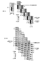
図9は、実施例2の印刷方法を説明する図である。図は、表刷り・白使用モードのバンド印刷の様子を示し、印刷に使用するノズルは図7と同様に、カラーノズル列Coの搬送方向下流側の半分のノズル(●・#1〜#5)を主画像用ノズルとし、ホワイトノズル列W及びカラーノズル列Coの搬送方向上流側の半分のノズル(△○・#6〜#10)を背景画像用ノズルとする。前述のように、本実施形態では、白使用モードの場合、往路動作と復路動作の間に搬送動作が実施されない第1印刷方法によって画像を印刷する。
<Example 2>
FIG. 9 is a diagram illustrating a printing method according to the second embodiment. The figure shows the state of band printing in the front printing / white use mode, and the nozzles used for printing are the half nozzles (● • # 1 to # 5 on the downstream side in the transport direction of the color nozzle row Co, as in FIG. ) Are the main image nozzles, and the half nozzles (Δ ○ # 6 to # 10) on the upstream side in the transport direction of the white nozzle row W and the color nozzle row Co are the background image nozzles. As described above, in the present embodiment, in the white use mode, an image is printed by the first printing method in which the transport operation is not performed between the forward pass operation and the return pass operation.
更に、実施例2では、主画像と背景画像のうち、媒体の所定領域に対して先に印刷する下層画像を、復路動作よりも先の動作である往路動作で印刷し、主画像と背景画像のうち、媒体の所定領域に対して後に印刷する上層画像を往路動作の後の動作である復路動作で印刷する。例えば、図9のように表刷りモードの場合には、主画像よりも背景画像の方が先に印刷される。よって、背景画像が往路動作で印刷され、主画像が復路動作で印刷される。つまり、実施例2では、主画像を印刷するパスと背景画像を印刷するパスが異なる。 Further, in the second embodiment, the lower layer image that is printed first with respect to the predetermined area of the medium among the main image and the background image is printed by the forward operation that is the operation before the return operation, and the main image and the background image are printed. Among them, an upper layer image to be printed later on a predetermined area of the medium is printed by a backward operation which is an operation after the forward operation. For example, in the front printing mode as shown in FIG. 9, the background image is printed earlier than the main image. Therefore, the background image is printed by the forward operation, and the main image is printed by the backward operation. That is, in the second embodiment, the pass for printing the main image is different from the pass for printing the background image.
具体的には、図9に示すように、まず、パス1の往路動作で背景画像用ノズル(△○)によって背景画像が印刷され、媒体が搬送されることなく、次のパス2の復路動作でヘッド41が移動方向に移動した後、搬送量5Dだけ媒体が搬送される。その後、パス3の往路動作で背景画像用ノズル(△○)によって背景画像が印刷され、媒体が搬送されることなく、パス4の復路動作で主画像用ノズル(●)によって主画像が印刷される。
Specifically, as shown in FIG. 9, first, the background image is printed by the background image nozzle (Δ ○) in the forward pass operation of
この場合、媒体の所定領域に対して下層画像である背景画像を印刷するパスから上層画像である主画像を印刷するパスまでの時間が、復路動作に要する時間と搬送動作に要する時間と往路動作に要する時間の合計時間となる。即ち、下層画像の乾燥時間が、往路動作及び復路動作に要する時間と搬送動作に要する時間の合計時間となる。よって、実施例2の方が図8に示す比較例よりも下層画像の乾燥時間を長くすることができる。更に、実施例2の方が図7に示す実施例1よりも、往路動作に要する時間分だけ下層画像の乾燥時間を長くすることができる。そのため、実施例2では、印刷画像の滲みや混色をより抑制し、印刷画像の画質劣化をより抑制することができる。 In this case, the time from the pass for printing the background image as the lower layer image to the pass for printing the main image as the upper layer image for the predetermined area of the medium is the time required for the return operation, the time required for the transport operation, and the forward operation. This is the total time required for. That is, the drying time of the lower layer image is the total time of the time required for the forward operation and the return operation and the time required for the conveyance operation. Therefore, the drying time of the lower layer image can be made longer in Example 2 than in the comparative example shown in FIG. Further, the drying time of the lower layer image can be made longer in the second embodiment than the first embodiment shown in FIG. Therefore, in the second embodiment, it is possible to further suppress the bleeding and color mixture of the print image, and to further suppress the deterioration of the image quality of the print image.
第1印刷方法では往路動作と復路動作の間に搬送動作が実施されないため、媒体の所定領域に対して同じノズルが往路動作と復路動作の2パスに亘って対向する。そこで、実施例2では、主画像と背景画像のうちの先に印刷する下層画像を出来る限り早く印刷するために往路動作で印刷し、後に印刷する上層画像を出来る限り遅く印刷するために復路動作で印刷する。そうすることで、下層画像を印刷するパスから上層画像を印刷するパスまでの乾燥時間を出来る限り長くすることができ、印刷画像の滲みや混色を抑制することができる。 In the first printing method, since the transport operation is not performed between the forward pass operation and the return pass operation, the same nozzle faces the predetermined area of the medium over two passes of the forward pass operation and the return pass operation. Therefore, in the second embodiment, the lower layer image to be printed first of the main image and the background image is printed in the forward operation to print as soon as possible, and the backward operation to print the upper layer image to be printed later as late as possible. Print with. By doing so, the drying time from the pass for printing the lower layer image to the pass for printing the upper layer image can be made as long as possible, and bleeding and color mixing of the printed image can be suppressed.
なお、実施例1(図7)では、主画像も背景画像も共に、往路動作と復路動作のうちの一方の動作で印刷する。そのため、往路と復路の特性差が排除された画像を印刷することができる。これに対して、実施例2では、主画像と背景画像のうちの一方は往路動作で印刷され、他方は復路動作で印刷される。ただし、実施例2においても、同じ画像は往路動作と復路動作のうちの一方の動作で印刷されるため、往路と復路の特性差が排除された画像を印刷することができる。 In the first embodiment (FIG. 7), both the main image and the background image are printed by one of the forward operation and the backward operation. Therefore, it is possible to print an image from which the difference in characteristics between the forward path and the backward path is eliminated. On the other hand, in the second embodiment, one of the main image and the background image is printed by the forward operation, and the other is printed by the backward operation. However, also in the second embodiment, the same image is printed by one of the forward path operation and the backward path operation, so that an image from which the characteristic difference between the forward path and the backward path is eliminated can be printed.
図10Aは、実施例2における裏刷り・白使用モードの印刷方法を説明する図である。裏刷りモードの場合、媒体の所定領域に対して背景画像よりも主画像が先に印刷される。よって、図10Aに示すように、カラーノズル列Coの搬送方向上流側の半分のノズル(●・#6〜#10)を主画像用ノズルとし、ホワイトノズル列Wおよびカラーノズル列Coの搬送方向下流側の半分のノズル(△○・#1〜#5)を背景画像用ノズルとする。実施例2では、下層画像を往路動作で印刷し、上層画像を復路動作で印刷する。よって、裏刷りモードでは、主画像を往路動作で印刷し、背景画像を復路動作で印刷する。そうすることで、下層画像の乾燥時間が往路動作及び復路動作に要する時間と搬送動作に要する時間の合計時間となり、比較例(図8)や実施例1(図7)よりも乾燥時間を長くすることができる。 FIG. 10A is a diagram illustrating a printing method in the back printing / white use mode according to the second embodiment. In the reverse printing mode, the main image is printed before the background image for a predetermined area of the medium. Therefore, as shown in FIG. 10A, the half nozzles (● # 6 to # 10) on the upstream side in the transport direction of the color nozzle row Co are used as main image nozzles, and the transport direction of the white nozzle row W and the color nozzle row Co The downstream half nozzles (Δ 側 # 1 to # 5) are set as background image nozzles. In the second embodiment, the lower layer image is printed by the forward operation, and the upper layer image is printed by the backward operation. Therefore, in the reverse printing mode, the main image is printed by the forward operation, and the background image is printed by the backward operation. By doing so, the drying time of the lower layer image becomes the total time of the time required for the forward operation and the backward operation and the time required for the conveyance operation, and the drying time is longer than that of the comparative example (FIG. 8) or Example 1 (FIG. 7). can do.
図10Bは、実施例2におけるインターレース印刷を説明する図である。ここまで、バンド印刷を例に挙げているがこれに限らず、例えば、インターレース印刷を実施してもよい。インターレース印刷とは、あるパスで形成されたラスターライン間に他のパスでラスターラインを形成する印刷方法である。即ち、インターレース印刷ではバンド印刷よりも搬送方向の印刷解像度が高くなる。図10Bでは、例えば、パス1のノズル#9,#10で形成されたラスターライン間に、パス2とパス3で2つのスターラインが形成される。そのため、図10Bのインターレース印刷では媒体搬送量が5D/3となり、図9のバンド印刷での媒体搬送量5Dよりも短くなる。そのため、インターレース印刷では、媒体の所定領域に対して下層画像(図10Bでは背景画像)を印刷するパスと上層画像(図10Bでは主画像)を印刷するパスの間に、媒体の所定領域がノズルと対向しないパスを設けることができる。よって、インターレース印刷の方がバンド印刷よりも、下層画像の乾燥時間をより長くすることができる。逆に言えば、バンド印刷のように、下層画像を印刷するパスと上層画像を印刷するパスの間にノズルと対向しないパスを設けることができない場合に、本発明がより有効であると言える。
FIG. 10B is a diagram illustrating interlaced printing according to the second embodiment. Up to this point, band printing has been described as an example. However, the present invention is not limited to this, and for example, interlaced printing may be performed. Interlaced printing is a printing method in which raster lines are formed in another pass between raster lines formed in a certain pass. That is, in interlace printing, the print resolution in the transport direction is higher than in band printing. In FIG. 10B, for example, two star lines are formed in
<実施例3>
図11は、実施例3の印刷方法を説明する図である。図は、表刷り・白使用モードにおけるバンド印刷の様子を示す。印刷に使用するノズルは、カラーノズル列Coの搬送方向下流側の半分のノズル(●・#1〜#5)を主画像用ノズルとし、ホワイトノズル列W及びカラーノズル列Coの搬送方向上流側の半分のノズル(△○・#6〜#10)を背景画像用ノズルとする。前述のように、本実施形態では、白使用モードの場合、往路動作と復路動作の間に搬送動作が実施されない第1印刷方法によって画像を印刷する。
<Example 3>
FIG. 11 is a diagram illustrating a printing method according to the third embodiment. The figure shows the state of band printing in the front printing / white use mode. The nozzles used for printing are the half nozzles (● # 1 to # 5) on the downstream side in the conveyance direction of the color nozzle row Co as main image nozzles, and the upstream side in the conveyance direction of the white nozzle row W and the color nozzle row Co. The half nozzles (.DELTA..
更に、実施例3では、主画像と背景画像のうちの一方の画像を2回のパスで印刷する。即ち、主画像と背景画像のうちの一方の画像を往路動作と復路動作で印刷する。そして、主画像と背景画像のうちの先に印刷する下層画像は少なくとも往路動作で印刷し、後に印刷する上層画像は少なくとも復路動作で印刷する。例えば、図11のように、表刷りモードにおいて背景画像を2回のパスで印刷する場合、背景画像を往路動作と復路動作で印刷し、主画像を復路動作で印刷する。この場合、媒体の所定領域に対して下層画像である背景画像を印刷するパスから上層画像である主画像を印刷するパスまでの時間、即ち、下層画像の乾燥時間が、搬送動作に要する時間と往路動作に要する時間の合計時間となる。よって、実施例3の方が図8に示す比較例よりも下層画像の乾燥時間を長くすることができる。その結果、印刷画像の滲みや混色を抑制し、印刷画像の画質劣化を抑制することができる。 Furthermore, in the third embodiment, one of the main image and the background image is printed in two passes. That is, one of the main image and the background image is printed by the forward path operation and the backward path operation. The lower layer image to be printed first of the main image and the background image is printed at least in the forward pass operation, and the upper layer image to be printed later is printed at least in the backward pass operation. For example, as shown in FIG. 11, when a background image is printed in two passes in the surface printing mode, the background image is printed by the forward operation and the backward operation, and the main image is printed by the backward operation. In this case, the time from the pass for printing the background image as the lower layer image to the pass for printing the main image as the upper layer image for the predetermined area of the medium, that is, the drying time of the lower layer image is the time required for the transport operation. This is the total time required for the forward movement. Therefore, the drying time of the lower layer image can be made longer in Example 3 than in the comparative example shown in FIG. As a result, it is possible to suppress bleeding and color mixing of the print image and to suppress deterioration in the image quality of the print image.
なお、図示しないが、表刷りモードにおいて主画像を2回のパスで印刷する場合、背景画像を往路動作で印刷し、主画像を往路動作と復路動作で印刷する。また、裏刷りモードにおいて背景画像を2回のパスで印刷する場合、主画像を往路動作で印刷し、背景画像を往路動作と復路動作で印刷し、裏刷りモードにおいて主画像を2回のパスで印刷する場合、主画像を往路動作と復路動作で印刷し、背景画像を復路動作で印刷する。これらの場合においても、媒体の所定領域に対して下層画像を印刷するパスから上層画像を印刷するパスまでの時間を、搬送動作に要する時間と往路動作または復路動作に要する時間との合計時間となる。よって、実施例3の方が比較例よりも下層画像の乾燥時間を長くすることができる。 Although not shown, when the main image is printed in two passes in the front printing mode, the background image is printed by the forward operation, and the main image is printed by the forward operation and the backward operation. When printing the background image in two passes in the reverse printing mode, the main image is printed in the forward pass operation, the background image is printed in the forward pass operation and the backward pass operation, and the main image is printed in the reverse pass mode in two passes. In the case of printing with the forward operation, the main image is printed by the forward operation and the backward operation, and the background image is printed by the backward operation. Even in these cases, the time from the pass for printing the lower layer image to the pass for printing the upper layer image on the predetermined area of the medium is the total time of the time required for the transport operation and the time required for the forward operation or the backward operation. Become. Therefore, in Example 3, the drying time of the lower layer image can be made longer than that in the comparative example.
また、主画像と背景画像のうちの一方の画像を2回のパスで印刷する場合、往路動作のドットと復路動作のドットを重ねて形成することができる。その結果、実施例3では、実施例1(図7)や実施例2(図9)に比べて、画像を構成するインク量を増やすことができる。例えば、背景画像を2回のパスで印刷する場合には、背景画像の遮蔽性を上げることができ、主画像を2回のパスで印刷する場合には、主画像の発色性を上げることができる。 In addition, when printing one image of the main image and the background image in two passes, it is possible to overlap the dots for the forward movement and the dots for the backward movement. As a result, the amount of ink constituting the image can be increased in the third embodiment compared to the first embodiment (FIG. 7) and the second embodiment (FIG. 9). For example, when the background image is printed in two passes, the background image can be shielded, and when the main image is printed in two passes, the main image can be colored. it can.
また、ドットを重ねて形成するに限らず、主画像と背景画像のうちの一方の画像を2回のパスで印刷する場合には、往路動作のドット形成位置と復路動作のドット形成位置を異ならせることができる。例えば、前述の図7に示す実施例1のように、背景画像を1回のパスでバンド印刷により印刷する場合、背景画像用の各ノズルが1回のパスで移動方向に並ぶドットを形成しなければならない。これに対して、図11の実施例3のように背景画像を2回のパスでバンド印刷により印刷する場合、背景画像用の各ノズルは往路動作と復路動作で移動方向に並ぶドットを交互に形成することができる、即ち、移動方向に並ぶドットを異なるパスで形成することができる。その結果、移動方向に並ぶドットの滲みや混色を抑制でき、印刷画像の画質劣化を抑制できる。 Further, not only when the dots are overlapped, but when one of the main image and the background image is printed in two passes, the dot formation position in the forward operation and the dot formation position in the backward operation are different. Can be made. For example, when the background image is printed by band printing in one pass as in the first embodiment shown in FIG. 7, the nozzles for the background image form dots arranged in the moving direction in one pass. There must be. On the other hand, when the background image is printed by band printing in two passes as in the third embodiment of FIG. 11, each nozzle for the background image alternately has dots arranged in the moving direction in the forward operation and the backward operation. In other words, dots arranged in the moving direction can be formed by different passes. As a result, it is possible to suppress blurring and color mixing of dots arranged in the moving direction, and it is possible to suppress deterioration in image quality of the printed image.
更に、2回のパスで画像を印刷する場合、ノズル列において搬送方向に並ぶノズルを往路動作と復路動作で交互で使用することができる。例えば、往路動作では偶数番号のノズルを使用し、復路動作では奇数番号のノズルを使用する。例えば、図11の場合には、背景画像用ノズル(#6〜#10)のうち、往路動作では偶数番号のノズル#6,#8,#10を使用し、復路動作では奇数番号のノズル#7,#9を使用するようにしてもよい。その結果、搬送方向に並ぶドットを異なるパスで印刷することができ、搬送方向に並ぶドットの滲みや混色を抑制できる。
Furthermore, when printing an image in two passes, the nozzles arranged in the transport direction in the nozzle row can be alternately used in the forward path operation and the backward path operation. For example, even-numbered nozzles are used in the forward operation, and odd-numbered nozzles are used in the backward operation. For example, in the case of FIG. 11, among the background image nozzles (# 6 to # 10), even-numbered
また、下層画像を2回のパスで印刷する場合、往路動作(先のパス)で印刷する画像部分(ドット)の方が、復路動作(後のパス)で印刷する画像部分(ドット)よりも、乾燥時間が長くなる。よって、下層画像を2回のパスで印刷する場合、往路動作で印刷する画像部分を復路動作で印刷する画像部分よりも大きくするとよい。逆に、上層画像を2回のパスで印刷する場合、復路動作(後のパス)で印刷する上層画像部分と重なる下層画像部分の方が、往路動作(先のパス)で印刷する上層画像部分と重なる下層画像部分よりも、乾燥時間が長くなる。よって、上層画像を2回のパスで印刷する場合、復路動作で印刷する画像部分を往路動作で印刷する画像部分よりも大きくするとよい。例えば、図11に示すように下層画像である背景画像を2回のパスで印刷する場合、往路動作では移動方向に並ぶ3個のドットのうちの2個のドットを形成し、復路動作では移動方向に並ぶ3個のドットのうちの1個のドットを形成するようにするとよい。また、往路動作で背景画像を印刷するノズル数(#6,#8,#10)を、復路動作で印刷するノズル数(#7,#9)よりも多くするとよい。そうすることで、下層画像のより多くの部分の乾燥時間を長くすることができ、画像の滲みや混色を抑制することができる。 In addition, when printing the lower layer image in two passes, the image portion (dot) printed in the forward pass (previous pass) is better than the image portion (dot) printed in the return pass (subsequent pass). , Drying time becomes longer. Therefore, when the lower layer image is printed in two passes, the image portion printed in the forward pass operation is preferably made larger than the image portion printed in the return pass operation. Conversely, when the upper layer image is printed in two passes, the lower layer image portion that overlaps the upper layer image portion that is printed in the backward pass operation (subsequent pass) is the upper layer image portion that is printed in the forward pass operation (previous pass). The drying time is longer than the lower layer image portion that overlaps with. Therefore, when the upper layer image is printed in two passes, it is preferable to make the image portion printed in the backward operation larger than the image portion printed in the forward operation. For example, as shown in FIG. 11, when a background image that is a lower layer image is printed in two passes, two out of three dots arranged in the movement direction are formed in the forward movement, and movement is performed in the backward movement. One of the three dots arranged in the direction may be formed. In addition, the number of nozzles (# 6, # 8, # 10) for printing the background image in the forward pass operation may be larger than the number of nozzles (# 7, # 9) for printing in the backward pass operation. By doing so, the drying time of more parts of the lower layer image can be lengthened, and bleeding and color mixing of the image can be suppressed.
以上、本実施形態では、白使用モードを実施する場合に、主画像と背景画像のうち、媒体の所定領域に対して先に印刷する画像用のノズルが、後に印刷する画像用のノズルよりも搬送方向上流側のノズルとなり、往路動作と復路動作と搬送動作が順に繰り返される第1印刷方法で画像が印刷され、各画像が往路動作と復路動作のうちの少なくとも一方で印刷されるように、プリンタードライバーが印刷データを作成したり並べ替えたりする。よって、プリンター1のコントローラー10とプリンタードライバーをインストールしたコンピューター60とが制御部に相当し、プリンター1とコントローラー10が接続された印刷システムが流体噴射装置に相当する。
ただし、これに限らず、プリンタードライバーの役割をプリンター1のコントローラー10が担ってもよく、この場合、プリンター1のコントローラー10が制御部に相当し、プリンター1単体が流体噴射装置に相当する。
As described above, in the present embodiment, when the white use mode is performed, the nozzle for an image that is printed first with respect to a predetermined area of the medium out of the main image and the background image is more than the nozzle for an image that is printed later. An image is printed by a first printing method in which a forward operation, a backward operation, and a transportation operation are sequentially repeated, and each image is printed by at least one of the forward operation and the backward operation. The printer driver creates or rearranges print data. Therefore, the
However, the present invention is not limited to this, and the
===変形例===
前述の図6のフローでは、白使用モードが選択された場合に、印刷方法が必ず第1印刷方法に設定されてしまうが、これに限らない。白使用モードが選択された場合に、推奨の印刷方法として(デフォルトとして)、第1印刷方法に設定されるようにしてもよい。そして、白使用モードであっても、ユーザーが設定画面等において、第2印刷方法を選択できるようにしてもよい。第1印刷方法よりも第2印刷方法の方が印刷時間を短縮できるため、ユーザーが早く印刷したい場合に(例えば試し印刷などにおいて)、白使用モードであっても第2印刷方法を実施できるようにしてもよい。
=== Modification ===
In the flow of FIG. 6 described above, when the white usage mode is selected, the printing method is always set to the first printing method, but the present invention is not limited to this. When the white use mode is selected, the first printing method may be set as a recommended printing method (as a default). Even in the white usage mode, the user may be able to select the second printing method on the setting screen or the like. Since the second printing method can shorten the printing time than the first printing method, the second printing method can be implemented even in the white usage mode when the user wants to print faster (for example, in trial printing). It may be.
前述の実施形態では、白インクと4色のインクを使用して白色の色味を調整した背景画像を例に挙げているが、これに限らない。白インクだけを用いて印刷した背景画像であっても良い。
また、前述の実施形態では、4色のインク(YMCK)だけで主画像を印刷しているが、これに限らない。例えば、4色のインクと共に白インクを用いて主画像を印刷してもよい。4色のインクに白インクを加えて主画像を印刷することで、高明度、且つ、高彩度の色を再現した画像を印刷することができる。この場合、前述の図7に示す表刷り・白使用モードの印刷では、ホワイトノズル列Wの搬送方向下流側のノズル群(#1〜#5)も用いて主画像を印刷することになる。
前述の実施形態では、白インクによって背景画像を印刷するとしているが、これに限らず、白以外の色インク(例えば、メタリック系のインク)によって背景画像を印刷してもよい。
In the above-described embodiment, the background image in which the white color is adjusted using the white ink and the four colors of ink is described as an example, but the present invention is not limited to this. It may be a background image printed using only white ink.
In the above-described embodiment, the main image is printed using only four colors of ink (YMCK). However, the present invention is not limited to this. For example, the main image may be printed using white ink together with four color inks. By printing the main image by adding the white ink to the four colors of ink, it is possible to print an image that reproduces a color with high brightness and high saturation. In this case, in the front printing / white use mode printing shown in FIG. 7 described above, the main image is printed using the nozzle group (# 1 to # 5) on the downstream side in the transport direction of the white nozzle row W.
In the above-described embodiment, the background image is printed with the white ink. However, the present invention is not limited to this, and the background image may be printed with a color ink other than white (for example, metallic ink).
前述の変形例3では、主画像と背景画像のうちの一方の画像を2回のパス(往路動作と復路動作)で印刷するとしているが、これに限らない。主画像も背景画像も2回のパスで印刷してもよい。この場合、主画像と背景画像のうちの下層画像を印刷するパスから上層画像を印刷するパスまでの時間が、比較例と同様に、搬送動作に要する時間となる。ただし、往路動作のドットと復路動作のドットを重ねなければ、1回のパスで噴射されるインク量が比較例よりも減り、また、移動方向や搬送方向に並ぶドットが異なるパスで形成される。そのため、下層画像の乾燥時間が比較例と同程度であっても、第1印刷方法を実施する本実施形態の方が、第2印刷方法を実施する比較例よりも、印刷画像の滲みや混色を抑制することができる。 In the third modification described above, one of the main image and the background image is printed in two passes (the forward pass operation and the return pass operation). However, the present invention is not limited to this. Both the main image and the background image may be printed in two passes. In this case, the time from the pass for printing the lower layer image of the main image and the background image to the pass for printing the upper layer image is the time required for the transport operation as in the comparative example. However, if the dots for the forward operation and the dots for the backward operation are not overlapped, the amount of ink ejected in one pass is smaller than that in the comparative example, and dots arranged in the movement direction and the transport direction are formed in different passes. . Therefore, even if the drying time of the lower layer image is about the same as that of the comparative example, the present embodiment in which the first printing method is performed is more blurred and mixed in the printed image than the comparative example in which the second printing method is performed. Can be suppressed.
===その他の実施の形態===
上記の各実施形態は、主としてインクジェットプリンターを有する印刷システムについて記載されているが、印刷方法等の開示が含まれている。また、上記の実施形態は、本発明の理解を容易にするためのものであり、本発明を限定して解釈するためのものではない。本発明は、その趣旨を逸脱することなく、変更、改良され得ると共に、本発明にはその等価物が含まれることはいうまでもない。
=== Other Embodiments ===
Each of the above embodiments is described mainly for a printing system having an ink jet printer, but includes disclosure of a printing method and the like. The above-described embodiments are for facilitating understanding of the present invention, and are not intended to limit the present invention. The present invention can be changed and improved without departing from the gist thereof, and it is needless to say that the present invention includes equivalents thereof.
<インクと記録媒体について>
本実施形態では、インクと該インクを吸収するインク吸収性の有る媒体(インク吸収性記録媒体)を用いる。インク吸収性記録媒体としては、インク吸収性の有る基材からなる記録媒体や基材にインク受容層を設けた記録媒体が使用可能である。インク吸収性の有る基材としては、紙、布などが挙げられる。インクは吸収性媒体に吸収されるインクであればよいが、インク吸収性媒体への吸収性を確保するために蒸発性の溶剤を含むことが好ましい。また、溶剤として水を少なくとも含む「水系インク」が特に好ましい。インクを構成する他の成分としては、色材としての染料や顔料がある。また、インクジェットヘッドからの吐出安定性のために水溶性の有機溶剤をも含有していてもよいし、保湿剤、浸透促進剤、ph調整剤、防虫剤、紫外線吸収剤などを必要により含有していてもよい。このようなカラーインクとして、例えば、特開2008−81693、特開2005−105135、特開2003−292834に記載のインクを使用できる。
<About ink and recording medium>
In this embodiment, ink and an ink-absorbing medium (ink-absorbing recording medium) that absorbs the ink are used. As the ink absorptive recording medium, a recording medium composed of a substrate having ink absorptivity or a recording medium provided with an ink receiving layer on the substrate can be used. Examples of the substrate having ink absorptivity include paper and cloth. The ink may be any ink that is absorbed by the absorbent medium, but preferably contains an evaporable solvent in order to ensure absorbability to the ink absorbent medium. Further, “water-based ink” containing at least water as a solvent is particularly preferable. As other components constituting the ink, there are dyes and pigments as color materials. In addition, it may contain a water-soluble organic solvent for ejection stability from an inkjet head, and if necessary, contains a moisturizing agent, a penetration enhancer, a ph regulator, an insect repellent, an ultraviolet absorber and the like. It may be. As such a color ink, for example, inks described in JP-A-2008-81693, JP-A-2005-105135, and JP-A-2003-292934 can be used.
記録媒体は、インク組成物の溶剤を吸収することでインク組成物の色材を固着するものである。例えば、紙、布などのインクを吸収する基材を用いた媒体でも良いし、インクを吸収する基材或いはインクを吸収しない基材にインクを吸収するインク受容層を設けたものでもよい。透明性の有る媒体を用いる場合は、例えば、特開2009−925、特開平9−99634、特開平9−208870に記載の記録媒体が使用できる。 The recording medium fixes the color material of the ink composition by absorbing the solvent of the ink composition. For example, a medium using a base material that absorbs ink such as paper or cloth may be used, or a base material that absorbs ink or a base material that does not absorb ink may be provided with an ink receiving layer that absorbs ink. When a transparent medium is used, for example, recording media described in JP-A-2009-925, JP-A-9-99634, and JP-A-9-208870 can be used.
インク受容層としては、インクジェット記録方法用の記録媒体上に通常設けられる公知のインク受容層を用いることができる。公知のインク受容層としては、例えば、樹脂からなるインク受容層が知られており、インク受容層に用いられる樹脂の例としては、例えば、特開昭57−38185号、同62−184879号公報等に開示されているようなポリビニルピロリドンもしくはビニルピロリドン−酢酸ビニル共重合体、特開昭60−168651号、同60−171143号、同61−134290号公報に開示されているようなポリビニルアルコールを主体とする樹脂組成物、特開昭60−234879号公報に開示されているようなビニルアルコールとオレフィン又はスチレンと無水マレイン酸との共重合体、特開昭61−74879号公報に開示されているようなポリエチレンオキサイドとイソシアネートとの架橋物、特開昭61−181679号公報に開示されているようなカルボキシメチルセルロースとポリエチレンオキサイドとの混合物、特開昭61−132377号公報に開示されているようなポリビニルアルコールにメタクリルアミドをグラフト化したポリマー、特開昭62−220383号公報に開示されているようなカルボキシル基を有するアクリル系ポリマー、特開平4−214382号公報等に開示されているようなポリビニルアセタール系ポリマー、特開平4−282282号、同4−285650号公報に開示されているような架橋性アクリル系ポリマー等種々のインク吸収性ポリマーを挙げることができる。 As the ink receiving layer, a known ink receiving layer usually provided on a recording medium for an ink jet recording method can be used. As the known ink receiving layer, for example, an ink receiving layer made of a resin is known. Examples of the resin used for the ink receiving layer include, for example, Japanese Patent Application Laid-Open Nos. 57-38185 and 62-184879. Polyvinyl pyrrolidone or vinyl pyrrolidone-vinyl acetate copolymer as disclosed in JP-A Nos. 60-168651, 60-171143, and 61-134290. Resin composition mainly, copolymer of vinyl alcohol and olefin or styrene and maleic anhydride as disclosed in JP-A-60-234879, disclosed in JP-A-61-74879 A cross-linked product of polyethylene oxide and isocyanate, as described in JP-A-61-1181679 A mixture of carboxymethyl cellulose and polyethylene oxide as shown, a polymer obtained by grafting methacrylamide to polyvinyl alcohol as disclosed in JP-A-61-2132377, JP-A-62-220383 An acrylic polymer having a carboxyl group as disclosed, a polyvinyl acetal polymer as disclosed in JP-A-4-214382, etc., and JP-A-4-282282 and 4-285650. And various ink-absorbing polymers such as crosslinkable acrylic polymers.
また、公知のインク受容層としては、特開平4−282282号、同4−285650号公報等には架橋性ポリマーから構成されるポリマーマトリックスと吸収性ポリマーとを併用したインク受容層が開示されている。更に、アルミナ水和物(カチオン性アルミナ水和物)を用いたインク受容層も知られており、例えば、特開昭60−232990号、同60−245588号公報、特公平3−24906号公報、特開平6−199035号、同7−82694号公報等には、微細な擬ベーマイト形アルミナ水和物を水溶性バインダーと共に基材表面に塗工した記録媒体が開示されている。また、例えば特開平10−203006号公報には、一次粒子径が3nm〜30nmである主として気相法による合成シリカを使用するインク受容層が開示されている。更にまた、特開2001−328344号公報には、無機顔料及び高分子接着剤を含むインク受容層が開示されている。本発明においては、これらの各インク受容層を設けたフィルム基材を用いることが好ましい。 As known ink receiving layers, JP-A-4-282282, 4-285650, etc. disclose an ink receiving layer using a polymer matrix composed of a crosslinkable polymer and an absorbent polymer in combination. Yes. Further, an ink receiving layer using alumina hydrate (cationic alumina hydrate) is also known, for example, JP-A-60-232990, JP-A-60-245588, and JP-B-3-24906. JP-A-6-199035 and JP-A-7-82694 disclose a recording medium in which fine pseudo boehmite type alumina hydrate is coated on a substrate surface together with a water-soluble binder. For example, Japanese Patent Application Laid-Open No. 10-203006 discloses an ink receiving layer using a synthetic silica mainly having a primary particle diameter of 3 nm to 30 nm by a vapor phase method. Furthermore, Japanese Patent Application Laid-Open No. 2001-328344 discloses an ink receiving layer containing an inorganic pigment and a polymer adhesive. In the present invention, it is preferable to use a film substrate provided with each of these ink receiving layers.
本発明方法においては、背景画像用の白インク組成物として、インクジェット記録方法において通常使用されている任意の白色インク組成物を用いることができる。このような白色顔料としては、例えば、無機白色顔料や有機白色顔料、白色の中空ポリマー微粒子を挙げることができ、白色インク組成物としては、着色剤成分として中空ポリマー微粒子を含有する水系インク組成物を用いることが好ましい。 In the method of the present invention, any white ink composition usually used in the ink jet recording method can be used as the white ink composition for the background image. Examples of such white pigments include inorganic white pigments, organic white pigments, and white hollow polymer fine particles. As the white ink composition, a water-based ink composition containing hollow polymer fine particles as a colorant component. Is preferably used.
無機白色顔料としては、硫酸バリウム等のアルカリ土類金属の硫酸塩、炭酸カルシウム等のアルカリ土類金属の炭酸塩、微粉ケイ酸、合成ケイ酸塩等のシリカ類、ケイ酸カルシウム、アルミナ、アルミナ水和物、酸化チタン、酸化亜鉛、タルク、クレイ等が挙げられる。特に酸化チタンは、隠蔽性、着色性及び分散粒径が好ましい白色顔料として知られている。 Examples of inorganic white pigments include alkaline earth metal sulfates such as barium sulfate, alkaline earth metal carbonates such as calcium carbonate, silicas such as finely divided silicic acid and synthetic silicates, calcium silicate, alumina, alumina Hydrates, titanium oxide, zinc oxide, talc, clay and the like can be mentioned. In particular, titanium oxide is known as a white pigment having preferable hiding properties, coloring properties, and dispersed particle sizes.
有機白色顔料としては、特開平11−129613号に示される有機化合物塩や特開平11−140365号、特開2001−234093号に示されるアルキレンビスメラミン誘導体が挙げられる。上記白色顔料の具体的な商品としては、ShigenoxOWP、ShigenoxOWPL、ShigenoxFWP、ShigenoxFWG、ShigenoxUL、ShigenoxU(以上、ハッコールケミカル社製、何れも商品名)などが挙げられる。 Examples of the organic white pigment include organic compound salts disclosed in JP-A No. 11-129613 and alkylene bismelamine derivatives disclosed in JP-A Nos. 11-14365 and 2001-234093. Specific examples of the white pigment include Shigenox OWP, Shigenox OWPL, Shigenox FWP, Shigenox FWG, Shigenox UL, and Shigenox U (all trade names manufactured by Hackol Chemical Co., Ltd.).
着色剤成分として含有させる中空ポリマー微粒子は、例えば、その外径が約0.1〜1μm、内径が約0.05〜0.8μmの微粒子であることができ、白色インク組成物の溶剤に不溶で、その他の成分、例えば、バインダー樹脂成分とは化学的に反応しないものであることが必要である。この中空ポリマー微粒子は、壁が液体を透過可能な合成重合体でつくられ、中空ポリマー微粒子中央部の空間はその壁を透過して液体の出入りが可能である。したがつて、この中空ポリマー微粒子中央部の空間はインク組成物の状態では溶媒によって満たされ、中空ポリマー微粒子の比重とインク組成物の比重が実質的に同一になり、中空ポリマー微粒子はインク組成物中に安定に分散されている。一方、このインク組成物を印字面に印字して乾燥すると、中空ポリマー微粒子中央部の空間は空気で置換されるため、樹脂と空間部で入射光が乱反射されて、実質的に白色を呈する。 The hollow polymer fine particles contained as the colorant component can be fine particles having an outer diameter of about 0.1 to 1 μm and an inner diameter of about 0.05 to 0.8 μm, and are insoluble in the solvent of the white ink composition. Thus, it is necessary that the component does not chemically react with other components, for example, a binder resin component. The hollow polymer fine particles are made of a synthetic polymer whose walls are permeable to liquid, and the space at the center of the hollow polymer fine particles can pass through the walls and allow liquid to enter and exit. Therefore, the space in the center of the hollow polymer fine particles is filled with the solvent in the state of the ink composition, and the specific gravity of the hollow polymer fine particles and the specific gravity of the ink composition are substantially the same. It is stably dispersed inside. On the other hand, when the ink composition is printed on the printing surface and dried, the space at the center of the hollow polymer fine particles is replaced with air, so that incident light is diffusely reflected between the resin and the space, and substantially white.
また、中空ポリマー微粒子は、前記のように、印刷前には微粒子内に液体を含有しているが、その微粒子内に入り込んでいた液体が印刷後に微粒子の璧を通過して拡散し、微粒子の微細気孔を空気で充満させるというタイプであるか、もしくは最初から内部に空気を含んだ完全密封タイプであることもできる。白色インク組成物に用いられる中空ポリマー微粒子はインク組成物中で沈殿しないことが望まれるため、インク組成物溶液の比重とほぼ同等の比重を有するものが好ましい。このため、必要に応じてグリセロールのような比重調整剤を用いてインク組成物溶液の比重を調節することが好ましい。 Further, as described above, the hollow polymer fine particle contains a liquid in the fine particle before printing, but the liquid that has entered the fine particle passes through the fine particle wall after printing and diffuses. It can be of a type in which fine pores are filled with air or a completely sealed type in which air is initially contained inside. Since it is desired that the hollow polymer fine particles used in the white ink composition do not precipitate in the ink composition, those having a specific gravity approximately equal to the specific gravity of the ink composition solution are preferable. For this reason, it is preferable to adjust the specific gravity of the ink composition solution using a specific gravity adjusting agent such as glycerol as necessary.
上記の性質を満たす中空ポリマー微粒子市販品としては、例えば、ローム・アンド・ハース(Rohm and Haas)社から市販されているロペーグ(Ropaque)OP−62等を挙げることができる。これは、アクリル・スチレン共重合体からなる中空ポリマー微粒子を38重量%含んだ水分散液である。この微粒子の内径は約0.3μmで、外径は約0.5μmであり、内部には水が充満している。 Examples of commercially available hollow polymer fine particles satisfying the above properties include Ropaque OP-62 commercially available from Rohm and Haas. This is an aqueous dispersion containing 38% by weight of hollow polymer fine particles made of an acrylic / styrene copolymer. The inner diameter of the fine particles is about 0.3 μm, the outer diameter is about 0.5 μm, and the inside is filled with water.
また、前記中空ポリマー微粒子は、公知の製造方法、例えば米国特許第4,089,800号明細書に開示されている方法により得ることもできる。この中空ポリマー微粒子は、実質的に有機重合体で作られており、熟可塑性を示す。中空ポリマー微粒子の製造に使用される熱可塑性樹脂としては、好ましくは、セルロース誘導体、アクリル樹脂、ポリオレフィン、ポリアミド、ポリカーポネート、ポリスチレン、スチレン若しくは他のビニルモノマーの共重合体、ビニルアセテート、ビニルアルコール、塩化ビニル又はビニルブチラールのホモ重合体あるいは共重合体のようなビニルポリマー、ジエンのホモ重合体及び共重合体等を挙げることができる。特に好ましい熱可塑性重合体としては、2−へキシルアクリレートの共重合体、メチルメタアクリレートの共重合体のような共重合体、スチレンとアクリロニトリルのようなその他のビニルモノマーとの共重合体を挙げることができる。 The hollow polymer fine particles can also be obtained by a known production method, for example, the method disclosed in US Pat. No. 4,089,800. The hollow polymer fine particles are substantially made of an organic polymer and exhibit mature plasticity. The thermoplastic resin used for the production of the hollow polymer fine particles is preferably a cellulose derivative, acrylic resin, polyolefin, polyamide, polycarbonate, polystyrene, styrene or other vinyl monomer copolymer, vinyl acetate, vinyl alcohol. And vinyl polymers such as vinyl chloride or vinyl butyral homopolymers or copolymers, diene homopolymers and copolymers, and the like. Particularly preferred thermoplastic polymers include copolymers of 2-hexyl acrylate, copolymers of methyl methacrylate, and copolymers of styrene and other vinyl monomers such as acrylonitrile. be able to.
本発明で用いる白色インク組成物中の中空ポリマー微粒子の含有量は、例えば、0.1〜20重量%とすることができる。中空ポリマー微粒子の含有量を0.1重量%以上にすると、充分な白色度を得ることができる。一方、20重量%以下にすると、インクジェット印刷用インク組成物に要求される粘度を確保するために必要なインクバインダー樹脂成分を充分な量で含有させることができ、その結果として、充分な印字密着性を確保することができる。 The content of the hollow polymer fine particles in the white ink composition used in the present invention can be, for example, 0.1 to 20% by weight. When the content of the hollow polymer fine particles is 0.1% by weight or more, sufficient whiteness can be obtained. On the other hand, if it is 20% by weight or less, a sufficient amount of the ink binder resin component necessary for ensuring the viscosity required for the ink composition for ink jet printing can be contained, and as a result, sufficient printing adhesion can be achieved. Sex can be secured.
本発明においては、前記の白色顔料を単独で用いてもよいし、併用してもよい。顔料の分散には、ボールミル、サンドミル、アトライター、ロールミル、アジテータ、ヘンシェルミキサ、コロイドミル、超音波ホモジナイザー、パールミル、湿式ジェットミル、ペイントシェーカー等を用いることができる。また、顔料の分散を行う際に分散剤を添加することも可能である。 In the present invention, the white pigment may be used alone or in combination. For the dispersion of the pigment, a ball mill, a sand mill, an attritor, a roll mill, an agitator, a Henschel mixer, a colloid mill, an ultrasonic homogenizer, a pearl mill, a wet jet mill, a paint shaker, or the like can be used. It is also possible to add a dispersant when dispersing the pigment.
本発明で用いる白色インク組成物は、白色着色剤成分の他に、インクジェット印刷用インク組成物に通常含有される種々の成分、例えば、樹脂成分、分散剤成分、溶媒成分(特に水)などを含有することができる。なお、本願明細書では溶媒と溶剤は同じ意味で用いる。また、中空ポリマー微粒子を白色着色剤として含有する白色インク組成物としては、例えば、特許第3562754号公報(特許文献1)又は特許第3639479号公報(特許文献2)に記載の組成物を用いることもできる。 The white ink composition used in the present invention contains, in addition to the white colorant component, various components usually contained in an ink composition for inkjet printing, such as a resin component, a dispersant component, a solvent component (especially water), and the like. Can be contained. In the present specification, the term “solvent” and “solvent” are used interchangeably. Moreover, as a white ink composition containing hollow polymer fine particles as a white colorant, for example, the composition described in Japanese Patent No. 3562754 (Patent Document 1) or Japanese Patent No. 3639479 (Patent Document 2) is used. You can also.
本発明で用いるカラー画像用の非白色インク組成物は、例えば、カラーインク組成物、黒色インク組成物、又は灰色インク組成物である。また、カラーインク組成物としては、例えば、シアンインク組成物、マゼンタインク組成物、イエローインク組成物、あるいはライトシアンインク組成物、ライトマゼンタインク組成物、更には、レッドインク組成物、グリーンインク組成物、又はブルーインク組成物等を挙げることができる。非白色インク組成物は、前記の各種インク組成物を1種又は2種以上の組合せで用いることができる。 The non-white ink composition for color images used in the present invention is, for example, a color ink composition, a black ink composition, or a gray ink composition. Examples of the color ink composition include a cyan ink composition, a magenta ink composition, a yellow ink composition, a light cyan ink composition, a light magenta ink composition, and a red ink composition and a green ink composition. Or a blue ink composition. As the non-white ink composition, the various ink compositions described above can be used alone or in combination of two or more.
非白色インク組成物としては、インクジェット記録方法において通常使用されている任意の非白色インク組成物を用いることができ、着色剤成分として染料又は顔料を含有する水系インク組成物を用いることが好ましい。特に、透明フィルム基材又はインク受容層に対して良好な特性(例えば、発色性や定着性)を示すインク組成物を用いることが好ましい。 As the non-white ink composition, any non-white ink composition usually used in the ink jet recording method can be used, and a water-based ink composition containing a dye or a pigment as a colorant component is preferably used. In particular, it is preferable to use an ink composition that exhibits good characteristics (for example, color developability and fixability) with respect to the transparent film substrate or the ink receiving layer.
本発明で用いるインクと記録媒体が上述のものであれば、前述の実施形態のように先の画像形成と後の画像形成の時間間隔を長く設けることで、インクの乾燥時間を長く設けることができ、画像の滲みや混色を防止することができる。ただし、本発明で用いるインクや記録媒体は上述のものに限るものでは無い。先の画像形成と後の画像形成の時間間隔を長く設けることで、インク中の成分が記録媒体に固着する時間を設けるものであればよい。即ち、前述の実施形態により先の画像形成と後の画像形成の時間間隔を長く設けることで、画像の滲みや混色を防止するものであれば、他のインクや記録媒体を用いても良い。 If the ink and recording medium used in the present invention are as described above, the ink drying time can be increased by providing a long time interval between the previous image formation and the subsequent image formation as in the above-described embodiment. Image blur and color mixing can be prevented. However, the ink and recording medium used in the present invention are not limited to those described above. Any time period may be used as long as the time interval between the previous image formation and the subsequent image formation is set so that the components in the ink adhere to the recording medium. In other words, other inks or recording media may be used as long as the time interval between the previous image formation and the subsequent image formation is set longer to prevent image bleeding and color mixing.
<プリンターについて>
前述の実施形態では、ヘッド41を移動方向に移動しながら単票紙に画像を形成する動作と、ヘッドに対して単票紙を搬送方向に搬送する動作と、を繰り返すプリンター1を例に挙げているが、これに限らない。例えば、印刷領域に搬送された連続用紙に対して、(複数の)ヘッド41を有するヘッドユニット40を媒体搬送方向に移動しながら画像を形成する動作と、ヘッドユニット40を紙幅方向に移動する動作と、を繰り返して画像を形成し、その後、未だ印刷されていない媒体部分を印刷領域に搬送するプリンターであってもよい。
<About the printer>
In the above-described embodiment, the
<流体噴射装置について>
前述の実施形態では、流体噴射装置としてインクジェットプリンターを例示しているが、これに限らない。流体噴射装置であれば、プリンター(印刷装置)ではなく、様々な工業用装置に適用可能である。例えば、布地に模様をつけるための捺染装置、カラーフィルター製造装置や有機ELディスプレイ等のディスプレイ製造装置、チップへDNAを溶かした溶液を塗布してDNAチップを製造するDNAチップ製造装置等であっても、本件発明を適用することができる。
また、ノズルからの流体噴射方式は、駆動素子(ピエゾ素子)に電圧をかけて圧力室を膨張・収縮させることにより流体を噴射するピエゾ方式でもよいし、発熱素子を用いてノズル内に気泡を発生させ、その気泡によって液体を噴射させるサーマル方式でもよい。
<About fluid ejection device>
In the above-described embodiment, an ink jet printer is exemplified as the fluid ejecting apparatus, but the present invention is not limited thereto. If it is a fluid ejecting apparatus, it can be applied to various industrial apparatuses, not a printer (printing apparatus). For example, a textile printing apparatus for applying a pattern to a fabric, a display manufacturing apparatus such as a color filter manufacturing apparatus or an organic EL display, a DNA chip manufacturing apparatus for manufacturing a DNA chip by applying a solution in which DNA is dissolved to a chip, and the like. Also, the present invention can be applied.
Further, the fluid ejection method from the nozzle may be a piezo method in which a fluid is ejected by applying a voltage to the driving element (piezo element) to expand and contract the pressure chamber, or bubbles are generated in the nozzle using a heating element. A thermal method may be used in which the liquid is generated and the liquid is ejected by the bubbles.
1 プリンター、10 コントローラー、11 インターフェース部、
12 CPU、13 メモリー、14 ユニット制御回路、
20 搬送ユニット、30 キャリッジユニット、31 キャリッジ、
40 ヘッドユニット、41 ヘッド、50 検出器群、
60 コンピューター
1 Printer, 10 Controller, 11 Interface section,
12 CPU, 13 memory, 14 unit control circuit,
20 transport unit, 30 carriage unit, 31 carriage,
40 head units, 41 heads, 50 detector groups,
60 computers
Claims (6)
(B)第2の流体を噴射するノズルが前記所定方向に並び、且つ、前記所定方向と交差する方向である移動方向に前記第1ノズル列と並ぶ第2ノズル列と、
(C)前記第1の流体による主画像の形成と、前記第2の流体による背景画像の形成とを、媒体に重ねて行う場合に、
前記第1ノズル列及び前記第2ノズル列と前記媒体とを前記移動方向の一方の方向に相対移動させる往路動作と、前記第1ノズル列及び前記第2ノズル列と前記媒体とを前記移動方向の他方の方向に相対移動させる復路動作と、前記第1ノズル列及び前記第2ノズル列に対する前記媒体の相対位置を前記所定方向の一方側に移動させる搬送動作とを、前記往路動作、前記復路動作、前記搬送動作の順に繰り返すことによって、前記媒体に画像を形成させ、
前記主画像を形成する前記第1ノズル列の一部のノズル群と前記背景画像を形成する前記第2ノズル列の一部のノズル群のうちの一方のノズル群であり、他方のノズル群よりも前記所定方向の他方側に位置する前記一方のノズル群を用いて、前記他方のノズル群よりも先に、前記媒体の所定領域に対して画像を形成させ、
前記主画像の形成のために、前記往路動作と前記復路動作のうちの少なくとも一方の動作時に前記ノズルから流体を噴射させ、
前記背景画像の形成のために、前記往路動作と前記復路動作のうちの少なくとも一方の動作時に前記ノズルから流体を噴射させる制御部と、
(D)を有することを特徴とする流体噴射装置。 (A) a first nozzle row in which nozzles that eject the first fluid are arranged in a predetermined direction;
(B) a second nozzle row in which nozzles for ejecting a second fluid are arranged in the predetermined direction and arranged in the moving direction that is a direction intersecting the predetermined direction;
(C) When the formation of the main image by the first fluid and the formation of the background image by the second fluid are performed on a medium,
A forward movement operation for relatively moving the first nozzle row, the second nozzle row, and the medium in one direction of the movement direction, and the movement direction of the first nozzle row, the second nozzle row, and the medium. The return path operation for moving the relative direction in the other direction of the first and the transport operation for moving the relative position of the medium to the one side in the predetermined direction with respect to the first nozzle row and the second nozzle row are the forward path operation and the return path By repeating the operation and the conveying operation in this order, an image is formed on the medium,
One of the nozzle groups of the first nozzle array that forms the main image and one of the nozzle groups of the second nozzle array that forms the background image, and the other nozzle group Also using the one nozzle group located on the other side of the predetermined direction, an image is formed on a predetermined area of the medium before the other nozzle group,
In order to form the main image, a fluid is ejected from the nozzle during at least one of the forward operation and the backward operation,
A controller that ejects fluid from the nozzle during at least one of the forward operation and the backward operation for forming the background image;
A fluid ejecting apparatus comprising (D).
前記媒体の所定領域に対して先に画像形成を行う前記一方のノズル群は、少なくとも前記往路動作時に流体を噴射する、
流体噴射装置。 The fluid ejection device according to claim 1,
The one nozzle group that performs image formation on a predetermined region of the medium first ejects fluid at least during the forward operation.
Fluid ejection device.
前記媒体の所定領域に対して後に画像形成を行う前記他方のノズル群は、少なくとも前記復路動作時に流体を噴射する、
流体噴射装置。 The fluid ejecting apparatus according to claim 1 or 2,
The other nozzle group that forms an image later on a predetermined area of the medium ejects fluid at least during the return path operation.
Fluid ejection device.
1回の前記往路動作に要する時間と1回の前記復路動作に要する時間のうちの少なくとも一方は、1回の前記搬送動作に要する時間よりも長い、
流体噴射装置。 The fluid ejecting apparatus according to any one of claims 1 to 3,
At least one of the time required for one forward operation and the time required for one return operation is longer than the time required for one transport operation;
Fluid ejection device.
前記背景画像を形成する前記第2ノズル列の一部のノズル群と前記所定方向の位置が同じである前記第1ノズル列の前記ノズルも使用して、前記背景画像を形成する、
流体噴射装置。 The fluid ejection device according to any one of claims 1 to 4,
The background image is formed using the nozzles of the first nozzle row whose position in the predetermined direction is the same as a part of the nozzle group of the second nozzle row that forms the background image.
Fluid ejection device.
前記第1の流体による主画像の形成と、前記第2の流体による背景画像の形成とを、媒体に重ねて行う場合に、
前記第1ノズル列及び前記第2ノズル列と前記媒体とを前記移動方向の一方の方向に相対移動させる往路動作と、前記第1ノズル列及び前記第2ノズル列と前記媒体とを前記移動方向の他方の方向に相対移動させる復路動作と、前記第1ノズル列及び前記第2ノズル列に対する前記媒体の相対位置を前記所定方向の一方側に移動させる搬送動作とを、前記往路動作、前記復路動作、前記搬送動作の順に繰り返すことによって、前記媒体に画像を形成し、
前記主画像を形成する前記第1ノズル列の一部のノズル群と前記背景画像を形成する前記第2ノズル列の一部のノズル群のうちの一方のノズル群であり、他方のノズル群よりも前記所定方向の他方側に位置する前記一方のノズル群を用いて、前記他方のノズル群よりも先に、前記媒体の所定領域に対して画像を形成し、
前記主画像の形成のために、前記往路動作と前記復路動作のうちの少なくとも一方の動作時に前記ノズルから流体を噴射し、
前記背景画像の形成のために、前記往路動作と前記復路動作のうちの少なくとも一方の動作時に前記ノズルから流体を噴射する、
ことを特徴とする流体噴射方法。 The first nozzle row in which the nozzles for ejecting the first fluid are arranged in a predetermined direction, and the nozzles for injecting the second fluid are arranged in the predetermined direction, and the moving direction is a direction intersecting the predetermined direction. A fluid ejecting method for a fluid ejecting apparatus having a second nozzle array aligned with one nozzle array,
When the formation of the main image by the first fluid and the formation of the background image by the second fluid are performed on a medium,
A forward movement operation for relatively moving the first nozzle row, the second nozzle row, and the medium in one direction of the movement direction, and the movement direction of the first nozzle row, the second nozzle row, and the medium. The return path operation for moving the relative direction in the other direction of the first and the transport operation for moving the relative position of the medium to the one side in the predetermined direction with respect to the first nozzle row and the second nozzle row are the forward path operation and the return path An image is formed on the medium by repeating the operation and the transport operation in this order,
One of the nozzle groups of the first nozzle array that forms the main image and one of the nozzle groups of the second nozzle array that forms the background image, and the other nozzle group And using the one nozzle group located on the other side of the predetermined direction to form an image on a predetermined area of the medium before the other nozzle group,
In order to form the main image, a fluid is ejected from the nozzle during at least one of the forward operation and the backward operation,
In order to form the background image, a fluid is ejected from the nozzle during at least one of the forward operation and the backward operation.
And a fluid ejection method.
Priority Applications (1)
| Application Number | Priority Date | Filing Date | Title |
|---|---|---|---|
| JP2010151331A JP2012011702A (en) | 2010-07-01 | 2010-07-01 | Apparatus and method for ejecting fluid |
Applications Claiming Priority (1)
| Application Number | Priority Date | Filing Date | Title |
|---|---|---|---|
| JP2010151331A JP2012011702A (en) | 2010-07-01 | 2010-07-01 | Apparatus and method for ejecting fluid |
Publications (1)
| Publication Number | Publication Date |
|---|---|
| JP2012011702A true JP2012011702A (en) | 2012-01-19 |
Family
ID=45598696
Family Applications (1)
| Application Number | Title | Priority Date | Filing Date |
|---|---|---|---|
| JP2010151331A Withdrawn JP2012011702A (en) | 2010-07-01 | 2010-07-01 | Apparatus and method for ejecting fluid |
Country Status (1)
| Country | Link |
|---|---|
| JP (1) | JP2012011702A (en) |
-
2010
- 2010-07-01 JP JP2010151331A patent/JP2012011702A/en not_active Withdrawn
Similar Documents
| Publication | Publication Date | Title |
|---|---|---|
| JP5655357B2 (en) | Printing apparatus and printing method | |
| JP5315645B2 (en) | Inkjet recording method for recording pattern layer and white solid coating layer on long sheet | |
| JP4095328B2 (en) | Inkjet recording apparatus, inkjet recording method and program | |
| JP5870499B2 (en) | Fluid ejecting apparatus and fluid ejecting method | |
| JP2008200850A (en) | Inkjet recording method for recording patterned layer and white solid coating layer | |
| JP2010142965A (en) | Image forming method | |
| JP5593795B2 (en) | Fluid ejecting apparatus and fluid ejecting method | |
| JP4642641B2 (en) | Inkjet recording method and inkjet recording apparatus | |
| JP5754537B2 (en) | Inkjet recording method | |
| JP2013010364A (en) | Inkjet recording method for recording pattern layer and white solid coating layer on long sheet | |
| JP2012024991A (en) | Fluid jetting apparatus and fluid jetting method | |
| JP2008200851A (en) | Inkjet recording method for recording patterned layer and white solid coating layer | |
| JP5652187B2 (en) | Fluid ejecting apparatus and fluid ejecting method | |
| JP6183408B2 (en) | Inkjet recording method | |
| JP5655457B2 (en) | Printing apparatus and printing method | |
| JP2012040866A (en) | Fluid jetting apparatus and fluid jetting method | |
| JP3972926B2 (en) | Inkjet recording method and inkjet recording apparatus | |
| JP2006264189A (en) | Inkjet recording device | |
| JP2012011702A (en) | Apparatus and method for ejecting fluid | |
| JP2005280334A (en) | Inkjet recording method and inkjet recording apparatus | |
| JP2008200853A (en) | Inkjet recording method for recording patterned layer and white solid coating layer | |
| JP5915719B2 (en) | Fluid ejecting apparatus and fluid ejecting method | |
| JP5621366B2 (en) | Printing apparatus and program | |
| JP2007145927A (en) | Ink set for inkjet and inkjet recording method | |
| JP3667076B2 (en) | Inkjet recording method and inkjet recording apparatus |
Legal Events
| Date | Code | Title | Description |
|---|---|---|---|
| A621 | Written request for application examination |
Free format text: JAPANESE INTERMEDIATE CODE: A621 Effective date: 20130318 |
|
| A761 | Written withdrawal of application |
Free format text: JAPANESE INTERMEDIATE CODE: A761 Effective date: 20130530 |