JP6173322B2 - Prestressed glass roll - Google Patents
Prestressed glass roll Download PDFInfo
- Publication number
- JP6173322B2 JP6173322B2 JP2014533797A JP2014533797A JP6173322B2 JP 6173322 B2 JP6173322 B2 JP 6173322B2 JP 2014533797 A JP2014533797 A JP 2014533797A JP 2014533797 A JP2014533797 A JP 2014533797A JP 6173322 B2 JP6173322 B2 JP 6173322B2
- Authority
- JP
- Japan
- Prior art keywords
- glass
- layer
- intermediate material
- roll
- glass film
- Prior art date
- Legal status (The legal status is an assumption and is not a legal conclusion. Google has not performed a legal analysis and makes no representation as to the accuracy of the status listed.)
- Active
Links
- 239000011521 glass Substances 0.000 title claims description 565
- 239000000463 material Substances 0.000 claims description 246
- 238000004804 winding Methods 0.000 claims description 62
- 239000006261 foam material Substances 0.000 claims description 20
- 230000003068 static effect Effects 0.000 claims description 18
- 230000005484 gravity Effects 0.000 claims description 15
- 238000004519 manufacturing process Methods 0.000 claims description 14
- 239000002985 plastic film Substances 0.000 claims description 11
- 229920006255 plastic film Polymers 0.000 claims description 11
- 238000000034 method Methods 0.000 claims description 10
- 229920000098 polyolefin Polymers 0.000 claims description 8
- 230000003746 surface roughness Effects 0.000 claims description 7
- 239000011111 cardboard Substances 0.000 claims description 6
- 230000008569 process Effects 0.000 claims description 4
- 239000011087 paperboard Substances 0.000 claims description 2
- 239000010410 layer Substances 0.000 description 263
- 239000010408 film Substances 0.000 description 231
- 239000011162 core material Substances 0.000 description 53
- 230000035882 stress Effects 0.000 description 42
- 238000006073 displacement reaction Methods 0.000 description 13
- 238000009826 distribution Methods 0.000 description 9
- 238000000576 coating method Methods 0.000 description 8
- 230000006378 damage Effects 0.000 description 7
- 239000000853 adhesive Substances 0.000 description 6
- 230000001070 adhesive effect Effects 0.000 description 6
- 239000011248 coating agent Substances 0.000 description 6
- 239000000123 paper Substances 0.000 description 6
- 238000012545 processing Methods 0.000 description 6
- 238000005452 bending Methods 0.000 description 5
- 230000008901 benefit Effects 0.000 description 5
- 230000006835 compression Effects 0.000 description 5
- 238000007906 compression Methods 0.000 description 5
- 230000009471 action Effects 0.000 description 4
- 239000006260 foam Substances 0.000 description 4
- 239000011229 interlayer Substances 0.000 description 4
- 238000005259 measurement Methods 0.000 description 4
- 230000007935 neutral effect Effects 0.000 description 4
- 239000002245 particle Substances 0.000 description 4
- -1 polyethylene Polymers 0.000 description 4
- 239000004698 Polyethylene Substances 0.000 description 3
- 238000003280 down draw process Methods 0.000 description 3
- 239000000428 dust Substances 0.000 description 3
- 230000000694 effects Effects 0.000 description 3
- 239000005357 flat glass Substances 0.000 description 3
- 229910052751 metal Inorganic materials 0.000 description 3
- 238000007500 overflow downdraw method Methods 0.000 description 3
- 229920000573 polyethylene Polymers 0.000 description 3
- 239000000843 powder Substances 0.000 description 3
- 230000001681 protective effect Effects 0.000 description 3
- 239000000126 substance Substances 0.000 description 3
- 238000012360 testing method Methods 0.000 description 3
- 230000001133 acceleration Effects 0.000 description 2
- 239000003513 alkali Substances 0.000 description 2
- 230000005540 biological transmission Effects 0.000 description 2
- 239000003795 chemical substances by application Substances 0.000 description 2
- 238000005336 cracking Methods 0.000 description 2
- 238000010586 diagram Methods 0.000 description 2
- 239000002184 metal Substances 0.000 description 2
- 239000000203 mixture Substances 0.000 description 2
- 238000004806 packaging method and process Methods 0.000 description 2
- 238000013001 point bending Methods 0.000 description 2
- 229920006254 polymer film Polymers 0.000 description 2
- 229920002635 polyurethane Polymers 0.000 description 2
- 239000004814 polyurethane Substances 0.000 description 2
- 238000005096 rolling process Methods 0.000 description 2
- 230000007480 spreading Effects 0.000 description 2
- 238000003892 spreading Methods 0.000 description 2
- 238000003860 storage Methods 0.000 description 2
- 235000010624 Medicago sativa Nutrition 0.000 description 1
- 240000004658 Medicago sativa Species 0.000 description 1
- XUIMIQQOPSSXEZ-UHFFFAOYSA-N Silicon Chemical compound [Si] XUIMIQQOPSSXEZ-UHFFFAOYSA-N 0.000 description 1
- 229910000831 Steel Inorganic materials 0.000 description 1
- 230000003044 adaptive effect Effects 0.000 description 1
- 230000032683 aging Effects 0.000 description 1
- 229910052782 aluminium Inorganic materials 0.000 description 1
- XAGFODPZIPBFFR-UHFFFAOYSA-N aluminium Chemical compound [Al] XAGFODPZIPBFFR-UHFFFAOYSA-N 0.000 description 1
- 239000005407 aluminoborosilicate glass Substances 0.000 description 1
- 239000005388 borosilicate glass Substances 0.000 description 1
- 239000003990 capacitor Substances 0.000 description 1
- 230000008859 change Effects 0.000 description 1
- 239000002131 composite material Substances 0.000 description 1
- 239000006059 cover glass Substances 0.000 description 1
- 230000007423 decrease Effects 0.000 description 1
- 230000003247 decreasing effect Effects 0.000 description 1
- 230000007547 defect Effects 0.000 description 1
- 230000001419 dependent effect Effects 0.000 description 1
- 238000009792 diffusion process Methods 0.000 description 1
- 238000010292 electrical insulation Methods 0.000 description 1
- 238000005516 engineering process Methods 0.000 description 1
- 239000008187 granular material Substances 0.000 description 1
- 238000003780 insertion Methods 0.000 description 1
- 230000037431 insertion Effects 0.000 description 1
- 230000003993 interaction Effects 0.000 description 1
- 239000005340 laminated glass Substances 0.000 description 1
- 239000010985 leather Substances 0.000 description 1
- 239000007788 liquid Substances 0.000 description 1
- 230000007246 mechanism Effects 0.000 description 1
- 239000012528 membrane Substances 0.000 description 1
- 239000007769 metal material Substances 0.000 description 1
- 229910044991 metal oxide Inorganic materials 0.000 description 1
- 150000004706 metal oxides Chemical class 0.000 description 1
- 230000003287 optical effect Effects 0.000 description 1
- 239000005022 packaging material Substances 0.000 description 1
- 230000002688 persistence Effects 0.000 description 1
- 239000004033 plastic Substances 0.000 description 1
- 229920003023 plastic Polymers 0.000 description 1
- 229920000728 polyester Polymers 0.000 description 1
- 229920000642 polymer Polymers 0.000 description 1
- 239000011148 porous material Substances 0.000 description 1
- 239000012779 reinforcing material Substances 0.000 description 1
- 239000004065 semiconductor Substances 0.000 description 1
- 238000000926 separation method Methods 0.000 description 1
- 230000035939 shock Effects 0.000 description 1
- 229910052710 silicon Inorganic materials 0.000 description 1
- 239000010703 silicon Substances 0.000 description 1
- 238000004544 sputter deposition Methods 0.000 description 1
- 239000010959 steel Substances 0.000 description 1
- 230000008646 thermal stress Effects 0.000 description 1
- 239000010409 thin film Substances 0.000 description 1
- 230000009466 transformation Effects 0.000 description 1
- 238000011282 treatment Methods 0.000 description 1
- XLYOFNOQVPJJNP-UHFFFAOYSA-N water Substances O XLYOFNOQVPJJNP-UHFFFAOYSA-N 0.000 description 1
- 238000004078 waterproofing Methods 0.000 description 1
- 239000002023 wood Substances 0.000 description 1
Images


Classifications
-
- B—PERFORMING OPERATIONS; TRANSPORTING
- B32—LAYERED PRODUCTS
- B32B—LAYERED PRODUCTS, i.e. PRODUCTS BUILT-UP OF STRATA OF FLAT OR NON-FLAT, e.g. CELLULAR OR HONEYCOMB, FORM
- B32B7/00—Layered products characterised by the relation between layers; Layered products characterised by the relative orientation of features between layers, or by the relative values of a measurable parameter between layers, i.e. products comprising layers having different physical, chemical or physicochemical properties; Layered products characterised by the interconnection of layers
- B32B7/04—Interconnection of layers
- B32B7/06—Interconnection of layers permitting easy separation
-
- B—PERFORMING OPERATIONS; TRANSPORTING
- B32—LAYERED PRODUCTS
- B32B—LAYERED PRODUCTS, i.e. PRODUCTS BUILT-UP OF STRATA OF FLAT OR NON-FLAT, e.g. CELLULAR OR HONEYCOMB, FORM
- B32B17/00—Layered products essentially comprising sheet glass, or glass, slag, or like fibres
- B32B17/06—Layered products essentially comprising sheet glass, or glass, slag, or like fibres comprising glass as the main or only constituent of a layer, next to another layer of a specific material
- B32B17/065—Layered products essentially comprising sheet glass, or glass, slag, or like fibres comprising glass as the main or only constituent of a layer, next to another layer of a specific material of paper or cardboard
-
- B—PERFORMING OPERATIONS; TRANSPORTING
- B32—LAYERED PRODUCTS
- B32B—LAYERED PRODUCTS, i.e. PRODUCTS BUILT-UP OF STRATA OF FLAT OR NON-FLAT, e.g. CELLULAR OR HONEYCOMB, FORM
- B32B17/00—Layered products essentially comprising sheet glass, or glass, slag, or like fibres
- B32B17/06—Layered products essentially comprising sheet glass, or glass, slag, or like fibres comprising glass as the main or only constituent of a layer, next to another layer of a specific material
- B32B17/066—Layered products essentially comprising sheet glass, or glass, slag, or like fibres comprising glass as the main or only constituent of a layer, next to another layer of a specific material of foam
-
- B—PERFORMING OPERATIONS; TRANSPORTING
- B32—LAYERED PRODUCTS
- B32B—LAYERED PRODUCTS, i.e. PRODUCTS BUILT-UP OF STRATA OF FLAT OR NON-FLAT, e.g. CELLULAR OR HONEYCOMB, FORM
- B32B3/00—Layered products comprising a layer with external or internal discontinuities or unevennesses, or a layer of non-planar shape; Layered products comprising a layer having particular features of form
- B32B3/26—Layered products comprising a layer with external or internal discontinuities or unevennesses, or a layer of non-planar shape; Layered products comprising a layer having particular features of form characterised by a particular shape of the outline of the cross-section of a continuous layer; characterised by a layer with cavities or internal voids ; characterised by an apertured layer
- B32B3/263—Layered products comprising a layer with external or internal discontinuities or unevennesses, or a layer of non-planar shape; Layered products comprising a layer having particular features of form characterised by a particular shape of the outline of the cross-section of a continuous layer; characterised by a layer with cavities or internal voids ; characterised by an apertured layer characterised by a layer having non-uniform thickness
-
- B—PERFORMING OPERATIONS; TRANSPORTING
- B32—LAYERED PRODUCTS
- B32B—LAYERED PRODUCTS, i.e. PRODUCTS BUILT-UP OF STRATA OF FLAT OR NON-FLAT, e.g. CELLULAR OR HONEYCOMB, FORM
- B32B3/00—Layered products comprising a layer with external or internal discontinuities or unevennesses, or a layer of non-planar shape; Layered products comprising a layer having particular features of form
- B32B3/26—Layered products comprising a layer with external or internal discontinuities or unevennesses, or a layer of non-planar shape; Layered products comprising a layer having particular features of form characterised by a particular shape of the outline of the cross-section of a continuous layer; characterised by a layer with cavities or internal voids ; characterised by an apertured layer
- B32B3/28—Layered products comprising a layer with external or internal discontinuities or unevennesses, or a layer of non-planar shape; Layered products comprising a layer having particular features of form characterised by a particular shape of the outline of the cross-section of a continuous layer; characterised by a layer with cavities or internal voids ; characterised by an apertured layer characterised by a layer comprising a deformed thin sheet, i.e. the layer having its entire thickness deformed out of the plane, e.g. corrugated, crumpled
-
- B—PERFORMING OPERATIONS; TRANSPORTING
- B32—LAYERED PRODUCTS
- B32B—LAYERED PRODUCTS, i.e. PRODUCTS BUILT-UP OF STRATA OF FLAT OR NON-FLAT, e.g. CELLULAR OR HONEYCOMB, FORM
- B32B3/00—Layered products comprising a layer with external or internal discontinuities or unevennesses, or a layer of non-planar shape; Layered products comprising a layer having particular features of form
- B32B3/26—Layered products comprising a layer with external or internal discontinuities or unevennesses, or a layer of non-planar shape; Layered products comprising a layer having particular features of form characterised by a particular shape of the outline of the cross-section of a continuous layer; characterised by a layer with cavities or internal voids ; characterised by an apertured layer
- B32B3/30—Layered products comprising a layer with external or internal discontinuities or unevennesses, or a layer of non-planar shape; Layered products comprising a layer having particular features of form characterised by a particular shape of the outline of the cross-section of a continuous layer; characterised by a layer with cavities or internal voids ; characterised by an apertured layer characterised by a layer formed with recesses or projections, e.g. hollows, grooves, protuberances, ribs
-
- B—PERFORMING OPERATIONS; TRANSPORTING
- B32—LAYERED PRODUCTS
- B32B—LAYERED PRODUCTS, i.e. PRODUCTS BUILT-UP OF STRATA OF FLAT OR NON-FLAT, e.g. CELLULAR OR HONEYCOMB, FORM
- B32B2266/00—Composition of foam
- B32B2266/02—Organic
- B32B2266/0214—Materials belonging to B32B27/00
- B32B2266/025—Polyolefin
-
- Y—GENERAL TAGGING OF NEW TECHNOLOGICAL DEVELOPMENTS; GENERAL TAGGING OF CROSS-SECTIONAL TECHNOLOGIES SPANNING OVER SEVERAL SECTIONS OF THE IPC; TECHNICAL SUBJECTS COVERED BY FORMER USPC CROSS-REFERENCE ART COLLECTIONS [XRACs] AND DIGESTS
- Y10—TECHNICAL SUBJECTS COVERED BY FORMER USPC
- Y10T—TECHNICAL SUBJECTS COVERED BY FORMER US CLASSIFICATION
- Y10T428/00—Stock material or miscellaneous articles
- Y10T428/24—Structurally defined web or sheet [e.g., overall dimension, etc.]
- Y10T428/24355—Continuous and nonuniform or irregular surface on layer or component [e.g., roofing, etc.]
-
- Y—GENERAL TAGGING OF NEW TECHNOLOGICAL DEVELOPMENTS; GENERAL TAGGING OF CROSS-SECTIONAL TECHNOLOGIES SPANNING OVER SEVERAL SECTIONS OF THE IPC; TECHNICAL SUBJECTS COVERED BY FORMER USPC CROSS-REFERENCE ART COLLECTIONS [XRACs] AND DIGESTS
- Y10—TECHNICAL SUBJECTS COVERED BY FORMER USPC
- Y10T—TECHNICAL SUBJECTS COVERED BY FORMER US CLASSIFICATION
- Y10T428/00—Stock material or miscellaneous articles
- Y10T428/24—Structurally defined web or sheet [e.g., overall dimension, etc.]
- Y10T428/24479—Structurally defined web or sheet [e.g., overall dimension, etc.] including variation in thickness
- Y10T428/24612—Composite web or sheet
-
- Y—GENERAL TAGGING OF NEW TECHNOLOGICAL DEVELOPMENTS; GENERAL TAGGING OF CROSS-SECTIONAL TECHNOLOGIES SPANNING OVER SEVERAL SECTIONS OF THE IPC; TECHNICAL SUBJECTS COVERED BY FORMER USPC CROSS-REFERENCE ART COLLECTIONS [XRACs] AND DIGESTS
- Y10—TECHNICAL SUBJECTS COVERED BY FORMER USPC
- Y10T—TECHNICAL SUBJECTS COVERED BY FORMER US CLASSIFICATION
- Y10T428/00—Stock material or miscellaneous articles
- Y10T428/24—Structurally defined web or sheet [e.g., overall dimension, etc.]
- Y10T428/24628—Nonplanar uniform thickness material
-
- Y—GENERAL TAGGING OF NEW TECHNOLOGICAL DEVELOPMENTS; GENERAL TAGGING OF CROSS-SECTIONAL TECHNOLOGIES SPANNING OVER SEVERAL SECTIONS OF THE IPC; TECHNICAL SUBJECTS COVERED BY FORMER USPC CROSS-REFERENCE ART COLLECTIONS [XRACs] AND DIGESTS
- Y10—TECHNICAL SUBJECTS COVERED BY FORMER USPC
- Y10T—TECHNICAL SUBJECTS COVERED BY FORMER US CLASSIFICATION
- Y10T428/00—Stock material or miscellaneous articles
- Y10T428/24—Structurally defined web or sheet [e.g., overall dimension, etc.]
- Y10T428/24752—Laterally noncoextensive components
- Y10T428/24769—Cellulosic
Landscapes
- Laminated Bodies (AREA)
- Storage Of Web-Like Or Filamentary Materials (AREA)
- Re-Forming, After-Treatment, Cutting And Transporting Of Glass Products (AREA)
Description
本発明は、個々のガラスフィルム層の間に中間材料を備えた、巻芯に巻き付けられたガラスフィルムから成るガラスロールに関する。 The present invention relates to a glass roll comprising a glass film wound around a core with an intermediate material between individual glass film layers.
例えば、消費者家電の分野において、例えば、半導体モジュール用、有機LED光源用、または、薄型もしくは曲げられた表示装置用のカバー・ガラスとして、あるいは再生エネルギーまたはエネルギー技術の分野において、例えば、太陽電池用に、といった様々な用途に薄板ガラスがますます使用されている。この例として、タッチパネル、コンデンサ、薄膜電池、フレキシブル回路基板、フレキシブルOLED、フレキシブル太陽光電池モジュール、または電子新聞も挙げられる。薄板ガラスは、耐薬品性、耐熱衝撃性、耐熱性、気密性、高い電気絶縁性能、適応した膨張係数、柔軟性、高い光学的品質、及び光透過性、またさらには、薄板ガラス両側の表面の先端熱加工によって非常に低粗度となった、高い面品位のような優れた特性により、多くの用途向けにますます注目を集めている。これに関連して、薄板ガラスは、約1.2mm未満の厚さから15μm以下までの厚さのガラスフィルムと解釈される。その柔軟性により、ガラスフィルムとしての薄板ガラスは、製造後に巻き上げられてガラスロールとして保管されること、もしくは梱包(Konfektionierung)又はさらなる加工のために輸送されることが多くなっている。ロール・ツー・ロール過程では、中間処理、例えば、表面のコーティング又は仕上げの後にも、ガラスフィルムを再び巻き上げて、その後の使用のために引き渡すことができる。ガラスの巻き上げは、平らに広げられた材料の保管及び輸送と比べて、保管、輸送、及びさらなる加工時の取り扱いをより安価かつコンパクトに行うことができるという利点がある。 For example, in the field of consumer electronics, for example, as cover glass for semiconductor modules, organic LED light sources, or thin or bent display devices, or in the field of renewable energy or energy technology, for example solar cells Thin glass is increasingly used for various purposes such as. Examples of this include a touch panel, a capacitor, a thin film battery, a flexible circuit board, a flexible OLED, a flexible solar cell module, or an electronic newspaper. Thin glass has chemical resistance, thermal shock resistance, heat resistance, air tightness, high electrical insulation performance, adaptive expansion coefficient, flexibility, high optical quality, and light transmission, and even the surfaces on both sides of the thin glass Due to its excellent properties, such as high surface quality, which have become very low roughness due to advanced thermal processing of steel, it is gaining more and more attention for many applications. In this context, thin glass is interpreted as a glass film with a thickness of less than about 1.2 mm up to 15 μm or less. Due to its flexibility, thin glass as a glass film is often rolled up after manufacture and stored as a glass roll, or transported for packaging or further processing. In a roll-to-roll process, the glass film can be rewound and handed over for subsequent use, even after intermediate treatments such as surface coating or finishing. Winding glass has the advantage that it can be cheaper and more compact to store, transport and handle during further processing compared to storing and transporting flattened material.
多くの優れた特性があるものの、ガラスは引張応力に対する抵抗性が乏しいので、脆性材料として、ガラスは破壊強度がとても低いものである。ガラスを曲げると、曲げられたガラスの外表面に引張応力が生じる。このようなガラスロールの無傷の保管及び無傷の輸送において、巻き上げられたガラスフィルムに亀裂や破断が生じることを回避するために、第一にエッジの品質及び健全性が重要である。ガラスフィルムにおいては、僅かな亀裂、例えば、微小亀裂のようなエッジの損傷でも、より大きい亀裂または破断の原因となり得る。さらに、巻き上げられたガラスフィルムの上面には引張応力がかかることから、巻き上げられたガラスフィルム内の亀裂や破断の発生を回避するためには、表面が健全であり、擦り傷、筋、または他の表面欠陥が無いことが重要である。第三に、巻き上げられたガラスフィルム内の亀裂や破断の発生を回避するために、製造に起因するガラスの内部応力もまた可能な限り低く、または存在していないことが求められる。しかし、商業生産においては、これら3つの要因はいずれも限定的にしか最適化することができないので、このような巻き上げられたガラスの壊れ易さによって、その材料特性の固有の限界がいずれにしてもさらに引き上げられてしまう。したがって、ガラスフィルムの巻き付け、ならびにそのようなガラスロールの保管及び輸送にとっては、ガラスの損傷を回避するために、特別な予防措置及び条件が重要である。 Although it has many excellent properties, glass has poor resistance to tensile stress, so as a brittle material, glass has very low fracture strength. When the glass is bent, tensile stress is generated on the outer surface of the bent glass. In order to avoid the occurrence of cracks and breaks in the wound glass film in such intact storage and transportation of the glass roll, first, the quality and soundness of the edge are important. In glass films, even minor cracks, such as edge damage such as microcracks, can cause larger cracks or breaks. Furthermore, since the upper surface of the rolled up glass film is subjected to tensile stress, the surface is healthy and scratches, streaks, or other conditions are avoided to avoid the occurrence of cracks and breaks in the rolled up glass film. It is important that there are no surface defects. Third, in order to avoid the occurrence of cracks and breaks in the rolled up glass film, it is required that the internal stress of the glass resulting from the production is also as low as possible or absent. However, in commercial production, all three of these factors can only be optimized to a limited extent, so that the inherent fragility of their material properties is in any way due to the fragility of such rolled up glass. Will be raised further. Therefore, special precautions and conditions are important for wrapping glass films and for storing and transporting such glass rolls in order to avoid glass damage.
ここで問題となるのは、一方では、ガラスロール上の個々のガラスフィルム層または全てのガラスフィルム層の揺れまたは振動である。他方では、巻き上げられたガラスの巻芯上における全体としての軸方向の変位が損傷をもたらすことである。さらに、個々のガラスフィルム層の、または全てのガラスフィルム層同士の、すなわち互いに対する、横方向への軸方向の変位が極めて重大である。そして、ガラスフィルム層が階段状に重なり合って位置するので、突出するエッジ領域が生じ、この領域が非常に破断し易くなる。ここでは、この作用をガラスフィルム層またはガラスロールの入れ子状の滑り出し(Teleskopieren)という言葉で言い換えることとする。この際、1つのガラスフィルム層に対して、さらなる1つまたは複数のガラスフィルム層の突出する領域が、特に破断または亀裂を生じ易く、これが外部からの衝撃、圧迫、もしくは接触によって、または揺れもしくは振動によってさらに助長されることがある。すなわち、ガラスフィルムの突出した領域は、この状態ではガラスロール結合体内で保護されていない。 The problem here is, on the one hand, the shaking or vibration of individual glass film layers or all glass film layers on the glass roll. On the other hand, the overall axial displacement on the wound glass core results in damage. Furthermore, lateral axial displacements of individual glass film layers or of all glass film layers, i.e. with respect to one another, are extremely important. And since a glass film layer overlaps and positions in a step shape, the edge area | region which protrudes arises and this area | region becomes very easy to fracture | rupture. Here, this action is paraphrased by the term telescopic nesting of the glass film layer or glass roll. In this case, for one glass film layer, the protruding region of one or more further glass film layers is particularly prone to breakage or cracking, which is caused by external impact, compression or contact, It may be further facilitated by vibration. That is, the protruding region of the glass film is not protected in the glass roll bonded body in this state.
さらに、ガラスフィルム層間の粒子状の異物によって損傷が生じることもまた回避しなければならない。一方では、異物は表面に傷を付けることがあり、これが特にガラスフィルム層同士の、もしくは互いに対する変位もしくは移動によって助長され、またはこの異物が点状の圧負荷を引き起こすことによって、亀裂もしくは破断をもたらす。 Furthermore, it must also be avoided that damage is caused by particulate foreign matter between the glass film layers. On the one hand, foreign objects can scratch the surface, which is particularly facilitated by displacement or movement of the glass film layers or relative to each other, or these foreign objects cause a point-like pressure load, thereby causing cracks or breaks. Bring.
ガラス表面間の埃粒子による薄板ガラスの破断を回避するために、WO87/06626は、ガラスロールを用いたロール・ツー・ロール法における薄板ガラスのコーティング方法に関して、ガラス層の間にプラスチックフィルムのような、ガラスを摩耗させない材料の1つまたは複数の層を設けることを提案している。ガラス上の金属被覆または金属酸化物被覆を保護するために、プラスチックフィルムはポリエステルまたはポリエチレンのようなポリマーであってもよく、また、型押しされたパターンを含んでいてもよい。ここでは、ガラスフィルム層の横方向の変位、揺れ又は振動の問題に対する解決策が提示されていない。また、ガラス表面または被覆表面と中間層材料との間の相互作用の問題に関しても、解決策が提示されていない。 In order to avoid the breakage of the thin glass due to dust particles between the glass surfaces, WO 87/06626 relates to a method of coating thin glass in a roll-to-roll method using a glass roll, like a plastic film between glass layers. It has been proposed to provide one or more layers of material that do not wear the glass. In order to protect the metal or metal oxide coating on the glass, the plastic film may be a polymer such as polyester or polyethylene and may include an embossed pattern. Here, no solution is presented to the problem of lateral displacement, shaking or vibration of the glass film layer. Also, no solution has been presented regarding the problem of interaction between the glass or coated surface and the interlayer material.
US3,622,298は、ガラスフィルムの製造及び巻き上げに関して、ガラスフィルム層間の中間層として包装紙を使用することにのみ言及しているが、例えば、輸送の際のガラスフィルム層の変位、揺れ、または振動の問題を認識していない。 US 3,622,298 only mentions the use of wrapping paper as an intermediate layer between glass film layers for the production and winding of glass films, for example, displacement, shaking of glass film layers during transport, Or do not recognize the problem of vibration.
US3,089,801は、包装紙またはアルミニウムフィルムの使用を開示しており、この紙が補強材として薄板ガラスに分離可能に貼り付けられている。これによって、曲げる際及び取り扱う際に、ガラスにより大きい強度が付与されることにより、巻き上げの際にもガラスが破断から保護される。しかし、この措置では、例えば、ガラスロールの輸送の際に、ガラスフィルム層の変位、揺れ、または振動によって生じるような、ガラスロール上のガラスフィルムの起こり得る破断の原因が阻止されない。また、貼り付けられた紙の層は、破断部品の崩壊を防止するのみであり、亀裂または破断の発生を防止しない。 US 3,089,801 discloses the use of wrapping paper or aluminum film, which is detachably affixed to thin glass as a reinforcing material. Thus, when bending and handling, the glass is protected from breakage even during winding by imparting greater strength to the glass. However, this measure does not prevent the possible breakage of the glass film on the glass roll, for example caused by displacement, shaking or vibration of the glass film layer during transport of the glass roll. Also, the affixed paper layer only prevents the broken parts from collapsing and does not prevent the occurrence of cracks or breaks.
US2011/0171417は、この点をさらに発展させて、薄板ガラスのエッジを保護するために、ガラスロールに巻き上げる前に、2つのプラスチックフィルムの間に薄板ガラスを積層することを提案している。薄板ガラスの一方の側面に粘着的に貼り付けられた支持層が提案されているが、この支持層は、薄板ガラスの縁部から突出している。薄板ガラスの他方の側面には、全面的にまたはエッジの領域にのみ、エッジから突出するようにカバー層が分離可能に貼り付けられているので、エッジが2つのプラスチックフィルム層の間に積層され、続いて薄板ガラスが巻き上げられる。US3,089,801の場合と同様に、ガラスロール上のガラスフィルムの破断の原因を阻止するための解決策が提案されていない。また、貼り付く中間層を分離する際にガラスフィルムが破断する恐れがあることも問題である。さらに、接着剤の粘着性の残留、または接着剤によるガラス表面への影響が、この解決案では極めて不都合である。 US2011 / 0171417 proposes to further develop this point and to laminate a sheet glass between two plastic films before winding it on a glass roll in order to protect the edge of the sheet glass. A support layer that is adhesively attached to one side surface of the thin glass has been proposed, but this support layer protrudes from the edge of the thin glass. On the other side of the thin glass, a cover layer is detachably attached so as to protrude from the edge entirely or only in the edge region, so that the edge is laminated between two plastic film layers. Subsequently, the sheet glass is rolled up. As in US 3,089,801, no solution has been proposed to prevent the cause of breakage of the glass film on the glass roll. Another problem is that the glass film may be broken when the intermediate layer to be attached is separated. Furthermore, adhesive stickiness persistence or the effect of the adhesive on the glass surface is extremely disadvantageous with this solution.
他方、WO2010/038760はこの問題を認識し、解決策として、ガラスフィルム層間の緩衝シートを横方向に突出させることを提案している。ガラスロールは、巻き上げられたガラスにより間隔を隔てられたフランジを有する巻芯を備えている。この横方向に突出する緩衝シート材は、巻芯上のガラスロール全体が横方向に変位した際に、または個々のガラスフィルム層が横方向に変位した際に、もしくはガラスフィルム層同士の入れ子状の滑り出しの際に、巻き上げられたガラスフィルムのエッジがフランジに衝突して破断することを防止する。ここでも、ガラスフィルム層または巻芯上のガラスの横方向の変位を防止するための解決策が提案されていないことが不都合である。その結果、突出する緩衝層または中間層があるにもかかわらず、ガラスロールが例えば、入れ子状に滑り出したとき、またはガラスフィルム層が共振したときガラスの破断が起こり得る。変位の際にエッジがフランジから間隔を隔てているという解決策のみが提供されている。また、さらに不都合な点は、ガラスロールを巻き出す際に、突出する中間層が互いに引っ掛かり、ガラスのエッジがその際に許容できない応力を受けて破断し得ることである。 On the other hand, WO2010 / 038760 recognizes this problem and proposes to make the buffer sheet between the glass film layers protrude in the lateral direction as a solution. The glass roll includes a winding core having flanges spaced apart by the rolled up glass. The buffer sheet material protruding in the lateral direction is formed when the entire glass roll on the winding core is displaced in the lateral direction, or when individual glass film layers are displaced in the lateral direction, or between the glass film layers. During the sliding, the edge of the rolled up glass film is prevented from colliding with the flange and breaking. Again, it is inconvenient that no solution has been proposed for preventing lateral displacement of the glass on the glass film layer or core. As a result, glass breakage may occur when the glass roll slides out, for example, in a nested manner, or when the glass film layer resonates despite the protruding buffer or intermediate layer. Only the solution that the edge is spaced from the flange during displacement is provided. A further disadvantage is that when the glass roll is unwound, the projecting intermediate layers get caught on each other, and the edges of the glass can break under unacceptable stresses.
US2011/0200812は、帯状ガラスまたはガラスフィルムを巻物状に巻き上げることを示しているが、ガラスフィルム巻物内に亀裂が生じることを回避するために、ガラスフィルムの2つの層の間に中間層を挿入している。この中間層は、US2011/0200812では、それによってガラスフィルムの損傷を回避し、ガラスロールに作用する外部の圧力を吸収するためにしか役立たない。 US2011 / 0200812 shows winding a glass strip or glass film into a roll, but in order to avoid cracks in the glass film roll, an intermediate layer is inserted between the two layers of the glass film. doing. This intermediate layer is only useful in US 2011/0200812, thereby avoiding damage to the glass film and absorbing external pressure acting on the glass roll.
WO2010/038760A1にも、個々のガラス層の間に中間層を挿入することによって、破断の危険性を回避したガラスロールが示されている。この文献も、破損回避のための中間層の挿入を示しているに過ぎない。 WO 2010/038760 A1 also shows a glass roll that avoids the risk of breakage by inserting an intermediate layer between the individual glass layers. This document also only shows the insertion of an intermediate layer to avoid breakage.
WO87/06626に示されたガラスロールでは、ガラスロール内で隣接するガラス層の表面を隔離するために、例えば、コーティング方法としてスパッタリングを用いて、個々のガラス層に被覆を設けている。この文献も、巻物内の隣接するガラス層同士の平面及びエッジでの接触を回避するために中間層を挿入することを示しているに過ぎない。巻き方が緩すぎる場合には、ガラス層同士が横方向に変位するか、または揺れたり振動したりする恐れがある。 In the glass roll shown in WO87 / 06626, in order to isolate the surface of the adjacent glass layer in the glass roll, for example, sputtering is used as a coating method, and the coating is provided on each glass layer. This document also only shows that an intermediate layer is inserted to avoid contact at the plane and edge between adjacent glass layers in the scroll. If the winding is too loose, the glass layers may be displaced laterally, or may be shaken or vibrated.
したがって、本発明は、上述の欠点を回避し、巻き上げられたガラスを高度に保護しながら、ガラスロールの変位、揺れ、または振動をも回避したガラスロールを提供することを課題とする。 Therefore, an object of the present invention is to provide a glass roll that avoids the above-mentioned drawbacks and that also avoids displacement, shaking, or vibration of the glass roll while highly protecting the rolled up glass.
本発明は、この課題を請求項1及び17、ならびに請求項41及び43の特徴によって解決する。さらなる構成は従属請求項2から16、18から40、及び42の対象である。 The present invention solves this problem by the features of claims 1 and 17 and claims 41 and 43. Further arrangements are the subject of the dependent claims 2 to 16, 18 to 40 and 42.
ガラスロールは、少なくとも1つのガラスフィルムと中間材料とを含んでおり、ガラスフィルム及び中間材料が互いに重なり合うように少なくともそれぞれ2層に巻芯に巻き付けられており、ガラスフィルム層が中間材料層によって固定されている。本願において、固定されているとは、極力真っ直ぐに巻かれた巻物の側面が、基本的に巻方向に交差する方向に力が作用する際に十分に維持され、ガラスロールの入れ子状の滑り出しが十分に回避されるような力が、ガラスロール内部の巻かれたガラス層の間に作用することと解釈される。 The glass roll includes at least one glass film and an intermediate material. The glass film and the intermediate material are wound around at least two layers so as to overlap each other, and the glass film layer is fixed by the intermediate material layer. Has been. In the present application, the term “fixed” means that the side surface of the roll wound as straight as possible is sufficiently maintained when a force is applied in a direction basically intersecting the winding direction, so that the nesting of the glass roll is prevented. It is interpreted that a force that is sufficiently avoided acts between the wound glass layers inside the glass roll.
本発明者らは、帯状ガラスのプレストレス力に応じて、ロール内部の摩擦に影響を及ぼし、それにより、ガラス層同士の変位、すなわちガラスロールの入れ子状の滑り出しを回避できることに気付いた。 The present inventors have found that depending on the prestressing force of the belt-shaped glass, the friction inside the roll is affected, whereby the displacement between the glass layers, that is, the nesting out of the glass roll can be avoided.
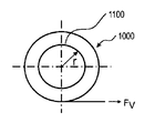
n層の巻層を有する巻物について考察すると、その層間に静止摩擦係数μが生じ、半径方向力FRが作用する場合、巻物材料と芯との間の摩擦力FFについて、次式が得られる。
FF=PF×AF×μ=FR×μ×n
Considering a scroll having n wound layers, when a static friction coefficient μ is generated between the layers and a radial force FR is applied, the following formula is obtained for the friction force FF between the roll material and the core.
FF = PF × AF × μ = FR × μ × n
半径方向力FRは、例えば、中間材料にかかる、巻き付けの際に調節可能なプレストレス力FVと一致する。つまり、FR=FVが成立する。 The radial force FR corresponds, for example, to a prestress force FV that can be adjusted during winding on the intermediate material. That is, FR = FV is established.
巻物が入れ子状に滑り出さないためには、巻物に作用する重力よりも摩擦力が大きいこと、すなわちFF>FGであることが求められる。最も内側のガラスフィルム層にかかる総質量に対する摩擦力の比が最も不利であるので、巻物は大抵の場合、最も内側の層において破損する。巻物に作用する重力は次式で表される。 In order to prevent the scroll from slipping out in a nested manner, it is required that the frictional force is greater than the gravity acting on the scroll, that is, FF> FG. Since the ratio of friction to total mass on the innermost glass film layer is the most unfavorable, scrolls often break at the innermost layer. The gravity acting on the scroll is expressed by the following equation.

上記の式において、各記号は以下を表している。
FV プレストレス力
FG 重力
FR 半径方向力
FF (巻物材料と芯との間の)摩擦力
n 巻層の数
b ガラス材料幅
r ロール半径(芯)
t1 ガラス厚さ
t2 中間層厚さ
μ 静止摩擦係数
PF 表面圧力
AF 作用表面
m 巻物材料の総質量
ρ ガラス密度
g=9.81m/s2 重力、重力加速度
In the above formula, each symbol represents the following.
FV Prestress force FG Gravity FR Radial force FF Friction force (between roll material and core) n Number of wound layers b Glass material width r Roll radius (core)
t1 Glass thickness t2 Intermediate layer thickness μ Static friction coefficient PF Surface pressure AF Working surface m Total mass of scroll material ρ Glass density g = 9.81 m / s 2 Gravity, gravity acceleration
式から明らかであるように、ロールの入れ子状の滑り出しを防止するには、比較的低いプレストレス力FV=FRのみが必要である。 As is apparent from the equation, only a relatively low prestress force FV = FR is required to prevent the rolls from slipping out.
本発明者らの功績は、予め関連付けを行うことによって、下記のような特性が既知であるあらゆる帯状ガラスについて、所与の巻層の数がnである場合に、n層の巻層を有するガラス巻物の入れ子状の滑り出しを防止するために必要となるプレストレス力FVを決定可能であることに気付いた点である。
b ガラス材料幅
r ロール半径(芯)
t1 ガラス厚さ
t2 中間層厚さ
μ 静止摩擦係数
ρ ガラス密度
The achievements of the inventors are that, by associating in advance, for every strip glass having the following characteristics known, when a given number of winding layers is n, it has n winding layers. It is the point which noticed that the prestress force FV required in order to prevent the glass slide from nesting out can be determined.
b Glass material width r Roll radius (core)
t1 Glass thickness t2 Intermediate layer thickness μ Static friction coefficient ρ Glass density
巻芯は通常、直径が200から600mmであり、木材、プラスチック、ボール紙、金属、または複合材料のような、あらゆる安定した材料から構成することができる。巻芯は表面に、適した滑り止め被覆、及び場合によっては圧縮性の被覆、または凹凸を付けた表面を備えていてもよい。 The core is typically 200 to 600 mm in diameter and can be composed of any stable material, such as wood, plastic, cardboard, metal, or composite material. The core may have a suitable anti-slip coating on the surface, and optionally a compressible coating, or an uneven surface.
ガラスフィルムは、所定の長さの連続する長い帯であり、ガラスフィルムはガラスロール内で連続する唯一の長さを有していてもよく、または複数のより短い長さのガラスフィルムがロールに巻き付けられていてもよい。通常、このようなガラスフィルムは、幅が300から800mm、長さが200から1000mの範囲内である。このようなガラスフィルムは、既知の方法で、ダウン・ドロー方式またはオーバーフロー・ダウン・ドロー・フュージョン方式で製造される。(例えば、ダウン・ドロー方式についてはWO02/051757A2、オーバーフロー・ダウン・ドロー・フュージョン方式についてはWO03/051783A1参照)。形成されて引き抜かれたエンドレス帯は、ガラスロールに巻き付けられて、仕様に応じた長さに切断される。 A glass film is a continuous long strip of a predetermined length, and the glass film may have a unique length that is continuous in the glass roll, or a plurality of shorter length glass films are in the roll. It may be wound. Usually, such glass films have a width of 300 to 800 mm and a length of 200 to 1000 m. Such a glass film is manufactured by a known method by a down draw method or an overflow down draw fusion method. (For example, refer to WO02 / 051757A2 for the down draw method and WO03 / 051783A1 for the overflow down draw fusion method). The endless strip formed and drawn is wound around a glass roll and cut to a length according to the specification.
この際、ガラスフィルムは、あらゆる適した種類のガラス、特にホウ珪酸ガラスまたはアルミノホウ珪酸ガラスから構成することができる。巻き上げの際の破断の危険性及び亀裂の発生を抑制するために、表面を先端熱加工し、非常に平滑にすることができる。これにより、表面は、曲げられたガラスの外側にかかるより高い引張応力を吸収することができ、より小さい半径で曲げることができる。表面粗さに応じて、各ガラスには表面にかかる限界応力があるが、この限界応力下では、その深さが表面粗さの程度である既に存在している初期亀裂が自然に進展してガラスを破壊する(脆性破壊)。ガラスが薄いほど、所与の曲げ半径によって表面に生成される応力が小さくなる。したがって、例えば、レーザ・スクライブされたエッジを有する、厚さが100μmのガラスフィルムは、破断させずに50mmの半径で、厚さが30μmのガラスフィルムは破断させずに24mmの半径で、または厚さが15μmのガラスフィルムは破断させずに12mmの半径で巻くことができる。厚さが50μmのガラスフィルムも破断させずに5mmの半径で巻くことができ、2mmの巻半径も可能である。特に、この好ましくは15〜30μmの厚さ範囲では、低アルカリガラスを薄く伸ばすことにより、特に平滑な表面がもたらされることが分かっている。 In this case, the glass film can be composed of any suitable type of glass, in particular borosilicate glass or aluminoborosilicate glass. In order to suppress the risk of breakage during cracking and the occurrence of cracks, the surface can be heat-treated at the tip to make it very smooth. This allows the surface to absorb higher tensile stresses on the outside of the bent glass and bend with a smaller radius. Depending on the surface roughness, each glass has a limit stress applied to the surface. Under this limit stress, the existing initial cracks whose depth is the degree of surface roughness naturally develop. Breaks glass (brittle fracture). The thinner the glass, the less stress is generated on the surface by a given bend radius. Thus, for example, a 100 μm thick glass film with a laser scribed edge has a radius of 50 mm without breaking, and a 30 μm thick glass film has a radius of 24 mm without breaking or is thick. A glass film having a thickness of 15 μm can be wound with a radius of 12 mm without breaking. A glass film having a thickness of 50 μm can be wound with a radius of 5 mm without breaking, and a winding radius of 2 mm is also possible. In particular, in this preferred thickness range of 15-30 μm, it has been found that thinly extending the low alkali glass results in a particularly smooth surface.
薄板ガラスを確実に無傷で巻くために、例えば、微小亀裂を十分に無くす先端熱加工のような適切な措置をエッジに施し、粗さが小さくなったエッジとする。そうすると、破断による破損確率の低い帯状ガラスの巻物を提供することができる。 In order to ensure that the thin glass is wound without any damage, for example, an appropriate measure such as tip thermal processing that sufficiently eliminates microcracks is applied to the edge to obtain an edge with reduced roughness. If it does so, the strip | belt-shaped glass scroll with the low breakage probability by a fracture | rupture can be provided.
特定の直径を有するガラス巻物の製造の実現性(Moglichkeit)は、破損確率によって表すことができる。すなわち、長さが1000m、厚さが5μmから350μm、特に15μmから200μmの範囲のガラスフィルムを、ロールの直径が50mmから1000mm、特に150mmから650mmの範囲のロールに巻き付ける場合において、多数のガラスフィルムを考察すると、帯状ガラスまたはガラスフィルムの破損確率は、1%未満である。 The feasibility of manufacturing a glass roll having a specific diameter can be represented by the probability of breakage. That is, when a glass film having a length of 1000 m and a thickness of 5 μm to 350 μm, particularly 15 μm to 200 μm is wound around a roll having a roll diameter of 50 mm to 1000 mm, particularly 150 mm to 650 mm, a large number of glass films , The probability of breakage of the strip glass or glass film is less than 1%.
表1には、様々なガラスフィルムについて、エッジ強度、すなわち、あるロール半径を有するガラスフィルムを巻き上げることによって生じる応力がMPaで示されている。 Table 1 shows, for various glass films, the edge strength, that is, the stress generated by rolling up a glass film having a certain roll radius in MPa.
ここでガラスは、マインツ所在のショット社(SCHOTT AG)製の、AF32eco、D263Teco、及びMEMpaxである。MPaで表された応力σは、μmで表されたガラス厚さd及びmmで表された巻回されたガラスロールの直径Dに応じて記載されている。エッジ強度、すなわち、帯状ガラスの外側に作用する応力を決定するための式は、次のように計算することができる。
σ=E・y/r
ここで、Eは弾性係数(E係数)、yは巻き上げられた帯状ガラスの厚さの半分d/2であり、rは巻き上げられた帯状ガラスの巻き上げ半径である。
The glass here is AF32eco, D263Teco, and MEMpax manufactured by SCHOTT AG, Mainz. The stress σ expressed in MPa is described according to the glass thickness d expressed in μm and the diameter D of the wound glass roll expressed in mm. The equation for determining the edge strength, i.e. the stress acting on the outside of the ribbon, can be calculated as follows.
σ = E · y / r
Here, E is an elastic coefficient (E coefficient), y is a half d / 2 of the thickness of the rolled-up glass strip, and r is a winding radius of the rolled-up glass ribbon.
分析対象の多数の試料の破断確率が分かっていれば、表1からのσの値を用いて特定の長さ及びロール半径を有する帯状ガラスの故障または破損確率Pを決定することができる。破断確率は、その幅がワイブル・パラメータによって特徴付けられるワイブル分布を示す。 If the rupture probabilities of a number of samples to be analyzed are known, the value of σ from Table 1 can be used to determine the failure or breakage probability P of a strip glass having a specific length and roll radius. The break probability indicates a Weibull distribution whose width is characterized by the Weibull parameter.
WIKIPEDIA(フリー百科事典)によれば、ワイブル分布は、ガラスのような脆性材料の寿命及び破損頻度を表すために使用される、正の実数の量を介した連続確率分布である。ワイブル分布は、技術システムの故障率を表すために使用することができる。ワイブル分布は、分布の幅、いわゆるワイブル係数によって特徴付けられる。一般に、この係数が大きいほど分布の幅が狭くなる。 According to WIKIPEDIA (Free Encyclopedia), the Weibull distribution is a continuous probability distribution through positive real quantities used to represent the lifetime and failure frequency of brittle materials such as glass. The Weibull distribution can be used to represent the failure rate of a technical system. The Weibull distribution is characterized by the width of the distribution, the so-called Weibull coefficient. In general, the larger the coefficient, the narrower the distribution width.
長さが50mmの試料を用いて二点曲げ測定を行う場合、ワイブル係数が分かっていれば、長さがLである帯状ガラスの破損確率を次のように決定することができる。 When two-point bending measurement is performed using a sample having a length of 50 mm, if the Weibull coefficient is known, the breakage probability of the glass strip having the length L can be determined as follows.
Pはロール半径rにおける、長さがLの帯状ガラスの破損確率、Lは破損確率に対して決定される帯状ガラスの長さ、lは二点試験の際に使用される、好ましくはl=50mmである関連試料の長さ、
σ(r)は、ロール半径rで巻き上げることによって生じる応力、μは二点曲げによって確定される応力、βは分布の幅とともに小さい強度への末端部を表すワイブル係数である。
P is the probability of breakage of the strip glass with length L at the roll radius r, L is the length of the strip glass determined with respect to the break probability, l is used in the two-point test, preferably l = The length of the relevant sample being 50 mm,
σ (r) is a stress generated by winding with a roll radius r, μ is a stress determined by two-point bending, and β is a Weibull coefficient representing a terminal portion to a small strength along with the width of the distribution.
破損確率の基準値を設定することは可能であるので、厚さdの帯状ガラスを半径rで巻き付ける際に、巻き上げ長さが1000mで破損確率が1%(またはそれ以下)を達成させたいのなら、二点測定の関連試料の長さが50mmであるとすると、次の条件を成立させることができる。 Since it is possible to set a standard value for the breakage probability, when winding a glass strip having a thickness d with a radius r, we want to achieve a breakage probability of 1% (or less) with a winding length of 1000 m. Then, if the length of the related sample for two-point measurement is 50 mm, the following condition can be established.
σ(r)について表1からの応力を借用すると、システムを特徴付ける、「性能指数」とも呼ばれるパラメータとして次式が得られる。 Borrowing the stress from Table 1 for σ (r) yields the following equation as a parameter, also called “performance index”, that characterizes the system.
好ましくは、例えば、先端熱加工のような処置を利用して、エッジ強度を高めることによって、αの値が例えば、12から14.5に上昇する。 Preferably, the value of α is increased from 12 to 14.5, for example, by increasing the edge strength using a procedure such as tip thermal processing.
本発明に従って巻き付けられるガラスフィルムは、通常、厚さが最大350μm、好適には最大100μm、好ましくは最大50μm、特に好ましくは最大30μm、及び最小5μm、好適には最小10μm、特に好ましくは最小15μmである。ここでの長所は、このような薄いガラスフィルムをその柔軟性によって、問題無く小さい半径で曲げて巻き付けることができることである。 The glass film to be wound according to the invention usually has a thickness of at most 350 μm, preferably at most 100 μm, preferably at most 50 μm, particularly preferably at most 30 μm and at least 5 μm, preferably at least 10 μm, particularly preferably at least 15 μm. is there. The advantage here is that such a thin glass film can be bent and wound with a small radius without problems due to its flexibility.
好ましいガラスフィルム厚さは、15、25、30、35、50、55、80、100、130、160、190、280μmである。 The preferred glass film thickness is 15, 25, 30, 35, 50, 55, 80, 100, 130, 160, 190, 280 μm.
本発明に従って巻き付けられるガラスフィルムは、特に前述の破損確率を実現するために、好ましくは、その両側の少なくとも一方の表面に、好ましくは両側の表面に、場合によっては少なくとも2つの対向するエッジに、先端熱加工された表面を有している。 The glass film wound according to the present invention is preferably on at least one surface on both sides, preferably on both surfaces, in some cases on at least two opposing edges, in particular in order to achieve the aforementioned probability of breakage. It has a tip heat-processed surface.
ガラスフィルムの両側の少なくとも一方の表面における二乗平均粗さ(RMS)Rqは、好適には最大1ナノメートル、好適には最大0.8ナノメートル、特に好ましくは最大0.5ナノメートルである。ガラスフィルムの両側の少なくとも一方の表面における平均表面粗さRaは、それぞれ測定長さを670μmとして、最大2ナノメートル、好適には最大1.5ナノメートル、特に好ましくは最大1ナノメートルである。好ましい一実施形態では、この粗度がガラスフィルムの両側の表面の特徴を示す。しかし、特に曲げた際に引張応力を受けるガラスフィルムの側面が、この粗度によって特徴付けられる。 The root mean square roughness (RMS) Rq on at least one surface on both sides of the glass film is preferably at most 1 nanometer, preferably at most 0.8 nanometer, particularly preferably at most 0.5 nanometer. The average surface roughness Ra on at least one surface on both sides of the glass film is a maximum of 2 nanometers, preferably a maximum of 1.5 nanometers, particularly preferably a maximum of 1 nanometer, with a measurement length of 670 μm. In a preferred embodiment, this roughness is characteristic of the surface on both sides of the glass film. However, the roughness of the glass film that is subjected to tensile stress, especially when bent, is characterized by this roughness.
この極めて平滑な表面によって、ガラス表面にかかる引張応力に起因する、支障となる破断の危険性を伴わずに、ガラスフィルムの曲げ及び巻き上げの負担が軽減されるが、ガラス表面の摩擦係数が非常に低いので、ガラスロール内のガラスフィルム層同士の、もしくは互いに対する横方向への変位、多少顕著なガラスフィルム層の入れ子状の滑り出し、または巻き上げられたガラスの巻芯上での横方向の変位及び逸脱もまた助長される。 This extremely smooth surface reduces the burden of bending and winding the glass film without the risk of hindering breakage due to tensile stress on the glass surface, but the friction coefficient of the glass surface is very high. Of the glass film layers in the glass roll, or lateral displacements between the glass film layers in the glass roll, or some conspicuous slipping out of the glass film layers, or lateral displacement on the wound glass core. And deviations are also encouraged.
本発明によれば、ガラスフィルム層が中間材料を通してガラスロールに固定されることによって、これが防止される。ガラスロールが巻き上げられた状態では、中間材料は、それぞれ各ガラスフィルム層の両側を少なくとも領域的に、しかし好適には全面的に覆っている。この際、まずは巻芯に少なくとも1つの中間材料層が巻かれ、その上に第1のガラスフィルム層が配置され、次に中間材料とガラスフィルムが交互に巻き上げられる。ガラスフィルム長さ全体が巻き付けられると、最後にさらに1つまたは複数の中間材料層がガラスロール周りに外側から巻かれることによって、最後のガラスフィルム層が固定される。 According to the invention, this is prevented by fixing the glass film layer to the glass roll through the intermediate material. In the state in which the glass roll is wound up, the intermediate material covers each side of each glass film layer at least locally, but preferably entirely. In this case, first, at least one intermediate material layer is wound around the winding core, the first glass film layer is disposed thereon, and then the intermediate material and the glass film are alternately wound up. When the entire length of the glass film is wound, the last glass film layer is fixed by finally winding one or more intermediate material layers from the outside around the glass roll.
最下位または内側の中間材料層、すなわち、巻芯と第1のガラスフィルム層との間の接触層は、代替的に別の材料で形成されるか、または巻芯を相応の固定材料でコーティングされる。最後の最上部のもしくは外側の中間材料層またはそれ以上の層を、代替的にまたは追加的に、例えば、特別な外側保護フィルムまたは紙、及び/又は粘着バンドもしくは固定バンドのような別の材料からなる層で形成してもよい。ここでは、内部の中間層の圧力を維持するために、最上部のガラスフィルム層が確実に固定されていることが重要である。 The lowermost or inner intermediate material layer, ie the contact layer between the core and the first glass film layer, is alternatively formed of another material or the core is coated with a corresponding fixing material Is done. The last top or outer intermediate material layer or more layers, alternatively or additionally, for example, a special outer protective film or paper, and / or another material such as an adhesive or fixing band You may form with the layer which consists of. Here, in order to maintain the pressure of the inner intermediate layer, it is important that the uppermost glass film layer is securely fixed.
本発明によれば、中間材料は巻き付けの際に、非常に大きな特定のプレストレスまたは引張応力により巻き付けられるが、それは、中間材料が所望の必要条件に応じて圧縮される、もしくは圧搾のために負荷をかけられる、または伸張されるような態様である。ロール・ツー・ロール過程においても、ガラスフィルムは巻き付けの際に、非常に大きな特定のプレストレスまたは引張応力により巻き付けられるが、それは、中間材料が所望の必要条件に応じて圧縮される、または圧搾のために負荷をかけられるような態様である。通常、中間材料の軽度の圧縮で十分である。圧縮によって、ガラスフィルム層が十分に固定されているというだけで概して用が足りており、高密度でコンパクトなガラスフィルム及び中間材料の巻物体が完成する。ガラスフィルム層は、圧縮性の中間材料によって固定される。 According to the present invention, the intermediate material is wound with a very large specific pre-stress or tensile stress when it is wound, because it is compressed or squeezed depending on the desired requirements. It is an aspect that is loaded or stretched. Even in the roll-to-roll process, the glass film is wound with a very large specific prestress or tensile stress when it is wound, which means that the intermediate material is compressed or squeezed depending on the desired requirements. It is the aspect which can be loaded for. Usually, a light compression of the intermediate material is sufficient. Compression is generally sufficient for the glass film layer to be sufficiently fixed, completing a dense, compact glass film and intermediate material roll. The glass film layer is fixed by a compressible intermediate material.
本発明の好ましい一実施形態では、中間材料は跳返性を有しており、圧縮された状態または圧搾された状態で、隣接するガラスフィルム表面に対して、相応な緩和力とともに復帰圧力を付加する。これにより、ガラスフィルム層が特に確実に固定される。圧縮性の中間材料は、ガラスフィルム層に対して復帰圧力を付加し、ここでは、ガラスフィルム層が圧縮性の中間材料によって固定される。 In a preferred embodiment of the present invention, the intermediate material is resilient and applies a return pressure with a corresponding relaxation force to the adjacent glass film surface in a compressed or squeezed state. To do. Thereby, a glass film layer is fixed especially reliably. The compressible intermediate material applies a return pressure to the glass film layer, where the glass film layer is fixed by the compressible intermediate material.
中間材料はガラス表面と協働して、変位に対するガラスフィルム層の固定の尺度となる特定の静止摩擦力を有する。この静止摩擦力は、ガラスフィルム表面に対する中間材料の復帰圧力もしくは表面圧力、または中間材料に対するガラスフィルムの復帰圧力もしくは表面圧力によって高められる。中間材料及びプレストレスに応じて、中間材料層によって付加される復帰圧力は、1から200kPa(キロパスカル)の値をとることができる。ガラスロール内のガラスフィルムの固定のための第3の要因は、非常に平滑なガラス表面への中間材料の付着性である。同様に、この付着性は、ガラスフィルム表面に対する中間材料の圧力、または中間材料に対するガラスフィルムの圧力によって高められる。 The intermediate material cooperates with the glass surface to have a specific static frictional force that is a measure of the fixation of the glass film layer against displacement. This static frictional force is increased by the return pressure or surface pressure of the intermediate material against the glass film surface, or the return pressure or surface pressure of the glass film against the intermediate material. Depending on the intermediate material and the prestress, the return pressure applied by the intermediate material layer can take values from 1 to 200 kPa (kilopascal). A third factor for the fixation of the glass film in the glass roll is the adhesion of the intermediate material to a very smooth glass surface. Similarly, this adhesion is enhanced by the pressure of the intermediate material on the glass film surface or the pressure of the glass film on the intermediate material.
したがって、中間材料はガラスフィルムとともに、ガラスロール内に静止摩擦力による摩擦接合を形成し、それにより、ガラスフィルムがガラスロール内で固定される。 Accordingly, the intermediate material together with the glass film forms a friction joint by static friction force in the glass roll, thereby fixing the glass film in the glass roll.
巻き付ける際の中間材料及び/又はガラスフィルムの引張応力が大きいほど、巻き込まれる空気が少なくなるので、ガラスロール結合体においてガラスロール内のガラスフィルム層の揺れまたは振動が防止される。中間材料及び/又はガラスフィルムを巻き付ける際のプレストレスまたは引張応力に応じて、巻き硬さが定義される。巻き硬さが大きいほど、ガラスフィルムがガラスロール内でより良好に固定される。 The greater the tensile stress of the intermediate material and / or the glass film during winding, the less the air that is entrained, so that the glass film layer in the glass roll is prevented from shaking or vibrating in the glass roll combination. The winding hardness is defined according to the prestress or tensile stress when winding the intermediate material and / or the glass film. The higher the winding hardness, the better the glass film is fixed in the glass roll.
さらに、ガラスフィルムのむらが、圧縮性の中間材料によって均一化される。それにより、ガラスフィルムの破断の原因となり得る応力の増加を回避することができる。このようなむらは、例えば、厚さ断面が異なることによる、「反り」(応力によって固定されたより大きい波形)及び「表面うねり」(表面の微細波形)である。 Further, the unevenness of the glass film is made uniform by the compressible intermediate material. Thereby, an increase in stress that can cause breakage of the glass film can be avoided. Such unevenness is, for example, “warping” (larger waveform fixed by stress) and “surface waviness” (fine surface corrugation) due to different thickness cross sections.
さらに、ガラスフィルム層間の粒子状の埃による異物が圧縮性の中間材料によって吸収されることにより、粒子とガラスフィルムとの間の応力ピークが補償され、ガラスフィルムの損傷を防止することができる。しかし、この際、ガラスフィルムの巻き上げ前から既にその表面上または中間材料の表面上に存在していた粒子のみが対象となる。 Furthermore, the foreign matter due to particulate dust between the glass film layers is absorbed by the compressible intermediate material, so that the stress peak between the particles and the glass film is compensated, and the glass film can be prevented from being damaged. However, at this time, only particles that have already existed on the surface of the glass film or on the surface of the intermediate material before the glass film is rolled up are targeted.
つまり、本発明によるガラスロールには、ガラスフィルムに作用する中間材料の復帰圧力による、ガラスフィルム層の高い巻き硬さ及び固定によって、ガラスフィルムの個々の層の間への埃の侵入に対してガラスロールの横側が確実に密閉され得たというさらなる利点がある。 In other words, the glass roll according to the present invention has a high winding hardness and fixing of the glass film layer due to the return pressure of the intermediate material acting on the glass film, thereby preventing dust from entering between the individual layers of the glass film. There is a further advantage that the side of the glass roll can be reliably sealed.
一実施形態では、ガラスフィルムのエッジを衝突から保護するために、中間材料層をガラスフィルムのエッジから横方向に突出させてもよい。この場合、ガラスロールを巻き出す際に中間材料層同士が引っ掛からないように突出量が制限されている。 In one embodiment, the intermediate material layer may protrude laterally from the edge of the glass film to protect the edge of the glass film from impact. In this case, the amount of protrusion is limited so that the intermediate material layers are not caught when the glass roll is unwound.
本発明の別の一構成では、巻物の幅にわたって延在する、またはそれを超えて外側へさえ至る中間層の代わりに、上述のようにより幅が狭い中間層または多数の中間層もしくは帯状中間層が設けられる。その際、個々の帯状中間層の幅は、巻かれた帯状ガラスの幅よりはるかに小さい。これは請求項17の対象である。請求項17によれば、ガラスフィルムが第1の幅を有しており、帯状中間材料のそれぞれが第2の幅を有しており、第2の幅B2が第1の幅B1よりもはるかに狭いことが要求される。 In another configuration of the invention, instead of an intermediate layer extending over the width of the scroll or even beyond the intermediate layer, a narrower intermediate layer or multiple intermediate layers or strips of intermediate layers as described above Is provided. In that case, the width of the individual strip-shaped intermediate layer is much smaller than the width of the rolled strip-shaped glass. This is the subject of claim 17. According to claim 17, the glass film has a first width, each of the strip-shaped intermediate materials has a second width, and the second width B2 is much greater than the first width B1. It is required to be narrow.
帯状中間層の幅は、摩擦力に対して事実上影響を及ぼさない。帯状中間層の幅を減少させると、自動的に表面圧力が高まる。表面圧力に作用表面を掛け合わせると半径方向力が得られ、次にこれを静止摩擦係数と合わせると摩擦力が得られる。他方で、複数の帯状ガラスを使用することにより、例えば、うねり、反りなどの幾何学的不規則性を非常に容易に補償することができる。これに対して、完全な平面状の中間層の場合は、不規則性を中間層材料の圧縮性においてのみ吸収することができる。そのために、中間層材料によっては、帯状ガラスが伝達することができない、ガラス強度及びそれによって不足する剛性により、中間層材料に対しても作用することができない、部分的に非常に高い力が必要である。この力は常に平衡状態にあるので、中間層材料の硬度に応じて応力が帯状ガラス内に相応の程度で同様に形成される。したがって、例えば、クリーンルーム用フィルムのような非圧縮性の中間層材料の場合、応力全体が帯状ガラスによって吸収される。 The width of the strip intermediate layer has virtually no effect on the frictional force. Reducing the width of the belt-like intermediate layer automatically increases the surface pressure. Multiplying the surface pressure by the working surface gives a radial force, which is then combined with the coefficient of static friction to give a frictional force. On the other hand, geometric irregularities such as waviness and warpage can be compensated very easily by using a plurality of glass strips. In contrast, in the case of a perfectly planar intermediate layer, irregularities can only be absorbed in the compressibility of the intermediate layer material. Therefore, depending on the intermediate layer material, a very high force is required which cannot be applied to the intermediate layer material due to the strength of the glass and the lack of rigidity due to the strength of the glass strip. It is. Since this force is always in an equilibrium state, stresses are similarly formed in the glass ribbon in a corresponding degree depending on the hardness of the interlayer material. Thus, for example, in the case of an incompressible intermediate layer material such as a clean room film, the entire stress is absorbed by the strip glass.
それに対して、細い帯状中間層を使用するという手段がある。これには、帯状ガラスの1つのガラスフィルムから次のガラスフィルムへの距離が維持されるという利点があるが、複数の細い帯状中間層を使用した際に、幾何学的な不規則性が細い帯状中間層の左右に、または中間空間内に広がってしまう。 On the other hand, there is a means of using a thin belt-like intermediate layer. This has the advantage that the distance from one glass film to the next glass film of the glass strip is maintained, but the geometric irregularities are small when using a plurality of thin belt interlayers. It spreads to the left and right of the belt-shaped intermediate layer or into the intermediate space.
また、帯状ガラスの特定の片側の湾曲も考えられる。このような帯状ガラスの場合、中立素分が画定される。中立素分は、帯状ガラスに沿った線であり、この線では、各巻層の帯状ガラス・エッジを互いに等間隔として帯状ガラスがエッジを揃えて巻き付けられたときに、圧力及び引張力が打ち消し合う。帯状に巻くことが可能な他の材料と比べて、湾曲した帯状ガラスは伸張または圧搾することができないので、このような帯状ガラスを巻き付ける際には、ガラス層が互いに対して円錐状に間隔を空ける、または巻物が漏斗状の巻になる。この漏斗状の巻物の内側は、巻物の圧負荷全体を吸収しなければならないが、これが概してエッジの損傷及び破断につながる。 Also, a specific one-sided curvature of the belt-like glass can be considered. In such a strip glass, a neutral element is defined. The neutral element is a line along the strip glass, and in this line, when the strip glass is wound with the strip glass edges of each winding layer being equally spaced from each other, the pressure and the tensile force cancel each other. . Compared to other materials that can be rolled into a band, curved banded glass cannot be stretched or squeezed, so when winding such a banded glass, the glass layers are conically spaced from one another. Empty or scroll becomes funnel-shaped. The inside of this funnel-shaped roll must absorb the entire pressure load of the roll, which generally leads to edge damage and breakage.
この問題を解決するために、少なくとも1つの帯状中間層を帯状ガラス上の中央に、中立素分に沿って載置することにより、その左右の中立素分の中間層の幅にわたって、多少コンパクトに巻くことができる。このように、帯状ガラスの幅の中央に細い帯状中間層を配置することが特に有利である。というのは、帯状ガラスが例えば、ダウン・ドロー設備の引張工程から由来したものであれば、帯状ガラスは平行な縁部を備えておらず、例えば、1キロメートルの半径を有する特定の曲率を有している場合が多い。その場合、このような帯状ガラスをロール状に巻き付けるとすれば、帯が漏斗状に巻き上げられるという問題が生じる。帯の一方側、つまり、曲げられた帯の外側に向けられた側面がその際緩く巻かれ、他方の側面、つまり内側に向けられた側面がきつく巻かれる。これにより、ガラスロールの全圧力が内部のエッジにかかることにより、ガラス・エッジの破断または損傷に至ることがある。これを防止するために、唯一のストライプまたは複数のストライプとして形成することができる、細いストライプのみを中間層として設ける。このストライプは好ましくは中央に配置されるので、個々の巻かれたガラス層の側面または縁部の互いに異なる間隔が自由に形成され、圧力が中間材料層の中央にかかる。その場合、ガラスロールの入れ子状の滑り出しを防止する保持力がガラスロールの中央に付与され、そうでなければ亀裂または破断が生じ易いエッジには付与されない。つまり、中間層を中央に導入することによって、特にエッジが平行ではない帯状ガラスの場合に、ガラスロールまたはガラス巻物が十分な安定性及び破断強度を有することが確実になる。 In order to solve this problem, by placing at least one strip intermediate layer in the center on the strip glass along the neutral element, the width of the intermediate layer of the left and right neutral elements is slightly more compact. Can be rolled up. Thus, it is particularly advantageous to arrange a thin strip-shaped intermediate layer in the center of the width of the strip-shaped glass. For example, if the glass ribbon is derived from the pulling process of a down draw facility, the glass ribbon does not have parallel edges and has a specific curvature with a radius of 1 kilometer, for example. There are many cases. In that case, if such a strip glass is wound in a roll shape, there arises a problem that the strip is wound up in a funnel shape. One side of the band, i.e. the side facing towards the outside of the bent band, is then loosely wound and the other side, i.e. the side facing inward, is tightly wound. This can cause the glass edge to break or be damaged by the total pressure of the glass roll being applied to the inner edge. In order to prevent this, only a thin stripe, which can be formed as a single stripe or a plurality of stripes, is provided as an intermediate layer. This stripe is preferably arranged in the center, so that different distances between the sides or edges of the individual wound glass layers are freely formed and pressure is applied to the center of the intermediate material layer. In that case, a holding force that prevents the glass roll from slipping out in a nested manner is applied to the center of the glass roll, and otherwise it is not applied to an edge that is liable to crack or break. In other words, by introducing the intermediate layer in the center, it is ensured that the glass roll or the glass roll has sufficient stability and breaking strength, particularly in the case of a strip glass whose edges are not parallel.
中間層の幅は、ガラス層または帯状ガラスの幅よりはるかに小さく、好ましくは帯状ガラスの幅の10から70%、好ましくは帯状ガラスの幅の30から50%である。 The width of the intermediate layer is much smaller than the width of the glass layer or strip glass, preferably 10 to 70% of the width of the strip glass, preferably 30 to 50% of the width of the strip glass.
細い中間層材料を使用するに当たり、唯一の層にも使用可能であるような、以下に挙げる全ての材料が考慮の対象となる。これらは、例えば、2mmから600mmの範囲内のようないずれの幅であってもよく、例えば、2から300個のような任意の数で使用することができる。個々の中間層の幅は、例えば、ガラス層の幅全体の0.1%から10%の間である。ひも、糸、粉体、及び顆粒も使用可能である。さらに、中間層が帯状中間層として形成されている場合、帯状中間層の幅を帯の途中で変化させる、すなわち、減少または増加させることも可能である。帯状中間層の幅は帯長さ全体にわたって必ずしも同じである必要は無い。 In using the thin interlayer material, all materials listed below are considered, which can be used for only one layer. These can be any width, for example in the range of 2 mm to 600 mm, and can be used in any number, for example, 2 to 300. The width of the individual intermediate layer is, for example, between 0.1% and 10% of the total width of the glass layer. Strings, threads, powders, and granules can also be used. Furthermore, when the intermediate layer is formed as a band-shaped intermediate layer, the width of the band-shaped intermediate layer can be changed in the middle of the band, that is, can be decreased or increased. The width of the belt-like intermediate layer does not necessarily have to be the same over the entire belt length.
中間材料は、中間材料として適切なあらゆる圧縮性材料である。特にその厚さも、ガラスロールの製造のための経済的な用途に対応しなければならない。その嵩密度が材料質量(構造物質)の密度よりも低い、例えば、発泡体膜のような、特に柔軟性の発泡体材料のような多孔質の材料が好ましい。これは、断面にわたって嵩密度がほぼ一定である均質な発泡体材料であってもよく、または一体発泡体材料であってもよい。このような一体発泡体材料は、断面にわたって嵩密度分布が異なっており、この嵩密度が断面中央に向かって減少する。このような発泡体の中間材料層は、曲げ挙動が有利であり、ほぼ無孔の表面への付着性が良好である。 The intermediate material is any compressible material suitable as an intermediate material. In particular, its thickness must also correspond to an economical application for the production of glass rolls. A porous material whose bulk density is lower than the density of the material mass (structural substance), such as a foam film, such as a flexible foam material, is preferred. This may be a homogeneous foam material with a substantially constant bulk density across the cross section, or it may be a monolithic foam material. Such monolithic foam materials have different bulk density distributions across the cross section, and the bulk density decreases toward the center of the cross section. Such a foam intermediate material layer has an advantageous bending behavior and good adhesion to a substantially non-porous surface.
中間材料として、発泡体材料、型押しされた又は他の方法で凹凸を付けられた紙、ボール紙、プラスチックフィルム、あるいは、粉体、パウダー、小片、もしくは粒子としてのウェブ構造を有する又は断片状な構造の金属フィルムのような圧縮性の材料が適している。好ましくは、材料として、圧縮性ボール紙、あるいは、例えば、ポリオレフィン発泡体材料、特に架橋ポリオレフィン発泡体材料からなる発泡体膜、またはポリエチレンもしくはポリウレタンからなる発泡体膜も使用される。発泡体材料は好ましくは独立気泡材料である。さらに、トラック用防水ほろ又は合革のような圧縮性材料もまた適している。 As an intermediate material, foam material, embossed or otherwise textured paper, cardboard, plastic film, or have a web structure as powder, powder, small pieces, or particles or fragmented A compressible material such as a metal film of a suitable structure is suitable. Preferably, a compressible cardboard or a foam film made of, for example, a polyolefin foam material, in particular a cross-linked polyolefin foam material, or a foam film made of polyethylene or polyurethane is preferably used as the material. The foam material is preferably a closed cell material. In addition, compressible materials such as waterproofing water for trucks or leather are also suitable.
さらに、結合が緩いまたは固い多層構造の中間材料も適している。その際、好ましくは、結合体の表面にガラスフィルムと接触する材料があり、結合体の芯には圧縮性の材料がある。この芯材料は、複数の層から構成されていてもよい。ガラスフィルム接触材料は、中間材料の表面にのみ配置されていてもよい。表面の材料は、ガラスフィルム表面と接触するように調整されている。この際、例えば、シリコンのような中間材料がガラス表面に残留しないように、またはイオン拡散が起こらないように、特に良好な化学的適合性が考慮される。また、ガラスフィルム表面の老化過程の変化が表面上に分散して異なって進行することを避けるべきである。これは後のコーティング過程にとって特に不都合であり、例えば、凹凸を付けた高度に多孔質の中間材料によって引き起こされ得る。中間材料結合体の芯の材料は、良好な圧縮作用及び好ましくは追加的に良好な復帰力の作用を重視して決められる。 In addition, intermediate materials with a loosely bonded or hard multilayer structure are also suitable. In that case, there is preferably a material in contact with the glass film on the surface of the bonded body, and a compressible material is provided in the core of the bonded body. This core material may be composed of a plurality of layers. The glass film contact material may be disposed only on the surface of the intermediate material. The surface material is adjusted to contact the glass film surface. In this case, particularly good chemical compatibility is taken into account, for example so that no intermediate material such as silicon remains on the glass surface or ion diffusion takes place. In addition, it should be avoided that the change in the aging process on the surface of the glass film progresses differently by being dispersed on the surface. This is particularly inconvenient for the subsequent coating process and can be caused, for example, by an uneven, highly porous intermediate material. The material of the core of the intermediate material combination is determined with emphasis on good compression action and preferably additionally good return force action.
中間材料の厚さは好ましくは2mm以下、特に好ましくは1mm以下、中でも特に好ましくは0.5mm以下の範囲内である。帯状ガラスが横方向の縁取り、すなわち縁部領域に厚さを増した部分を有する一実施形態では、中間材料もより厚く、8mmまでの厚さを有していてもよい。より厚い縁部領域のより薄いガラスフィルムへの幅にわたっての必要な均一化をもたらすために、複数の中間材料層を重なり合うように巻き上げてもよい。また、第1の中間材料層をガラスフィルムの幅全体にわたって、ならびにその上方及び/又はその下方に1つ又は複数のより細い中間材料層を、薄いガラスフィルム断面の幅内で、かつ、ガラスフィルム層間に配置してもよい。 The thickness of the intermediate material is preferably 2 mm or less, particularly preferably 1 mm or less, and particularly preferably within the range of 0.5 mm or less. In one embodiment where the glass ribbon has a lateral border, i.e. an increased thickness in the edge region, the intermediate material may also be thicker and have a thickness of up to 8 mm. Multiple intermediate material layers may be rolled up to overlap to provide the necessary uniformity across the width of the thicker edge region into a thinner glass film. Also, the first intermediate material layer extends over the entire width of the glass film, and one or more thinner intermediate material layers above and / or below it, within the width of the thin glass film cross section, and the glass film You may arrange | position between layers.
先端熱加工されたガラス表面と協働して、0.15から10Nの、好ましくは1から10Nの範囲の静止摩擦力FSを発揮する中間材料が好ましい。静止摩擦力は、力ピークとして解釈され、そして、その力は、中間材料がガラス表面に対して相対的に動き出すようになるべき値でなくてはならない。 An intermediate material that exerts a static frictional force F S in the range of 0.15 to 10 N, preferably in the range of 1 to 10 N, in cooperation with the tip heat-processed glass surface is preferred. The static friction force is interpreted as a force peak, and the force should be a value at which the intermediate material should begin to move relative to the glass surface.
さらに、先端熱加工されたガラス表面と協働して、0.15から5Nの、好ましくは0.2から2.5Nの、特に好ましくは1から2.5Nの範囲内の摩擦力FDを発揮する中間材料が好ましい。摩擦力は、静止摩擦力を克服した後の試験軌道上の平均力として解釈され、そして、その力は、中間材料とガラス表面との間の相対移動に必要となる。 Furthermore, in cooperation with the tip fire-polished glass surface, a 5N from 0.15, preferably from 2.5N 0.2, a frictional force F D in the range especially preferably 1 2.5N An intermediate material is preferred. Friction force is interpreted as the average force on the test track after overcoming the static friction force, and that force is required for relative movement between the intermediate material and the glass surface.
静止摩擦力FS及び摩擦力FDの値は、DIN 50 014に従った、23℃、相対湿度50%の標準気候において、1.96Nの垂直力を用いたシェンク・トレーベル(Schenck−Trebel)社の電気機械的汎用試験装置による、それぞれDIN EN ISO 8295に従った測定に相当する。
The values of the static friction force F S and the friction force F D are Schenck-Trebel with a normal force of 1.96 N in a standard climate of 23 ° C. and 50% relative humidity according to
別の本発明による一構成では、ガラスフィルムの少なくとも1つの側面を、プラスチックフィルム、特にポリマー膜でコーティングしてもよい。 In another configuration according to the invention, at least one side of the glass film may be coated with a plastic film, in particular a polymer film.
特別な一実施形態では、このプラスチックフィルムが中間材料を形成する。これにより、ガラスフィルムから分離された材料を、別のロール上に準備する、または巻き出しの際にロールから分離して取り外す必要が無いので、巻き上げ及び巻き出しが著しく容易になるという特別な利点がもたらされる。 In a special embodiment, this plastic film forms the intermediate material. This has the special advantage that the material separated from the glass film does not have to be prepared on a separate roll, or separated from the roll during unwinding and removed, making winding and unwinding significantly easier Is brought about.
本発明は、ガラスロールの製造方法をさらに含んでいる。この方法は、ガラスフィルム、巻芯、及び圧縮性の中間材料を準備する工程と、少なくとも1つの中間材料の内側の層を巻芯に巻き付ける工程と、ガラスフィルムが中間材料と交互に層状に巻芯に巻き付けられるように、ガラスフィルム及び中間材料を巻芯に巻き付ける工程とを含んでおり、中間材料及び/又はガラスフィルムが、長さ方向に作用する引張応力により巻き付けられ、その応力は、中間材料を圧縮し、ガラスロールにガラスフィルム端部を固定する。 The present invention further includes a method for producing a glass roll. This method comprises the steps of preparing a glass film, a core and a compressible intermediate material, winding an inner layer of at least one intermediate material around the core, and winding the glass film alternately with the intermediate material in layers. Winding the glass film and the intermediate material around the core so as to be wound around the core, the intermediate material and / or the glass film being wound by a tensile stress acting in the length direction, The material is compressed and the glass film ends are fixed to a glass roll.
巻芯は、十分な曲げ剛性及び耐圧性を有するあらゆる安定した材料から構成することができる。中間材料は、ロールに巻き付けて準備することが実用的である。ガラスフィルムは、ダウン・ドロー方式もしくはオーバーフロー・ダウン・ドロー・フュージョン方式のような製造過程から、エンドレス帯として、またはガラスロールとして巻き上げられて準備される。 The core can be composed of any stable material with sufficient bending rigidity and pressure resistance. It is practical to prepare the intermediate material by winding it around a roll. The glass film is prepared by being wound up as an endless belt or as a glass roll from a manufacturing process such as a down-draw method or an overflow-down-draw fusion method.
中間材料のうち、まずは1つまたは複数の層が巻芯に巻き付けられることによって、到来する中間材料と既に巻き上げられた中間材料と間にまち(襠)が生じる。このまちに、巻き上げられる帯状ガラスフィルムの長さの始端部が挿入されて、中間材料と交互に層状に巻き上げられる。したがって、ガラスフィルムは両方の表面が、好ましくは全面が中間材料によって覆われている。この際、中間材料供給ロールの巻き出し及びガラスロールの巻き上げの互いに対する速度比を制御することによって、中間材料が、その長さ方向に作用する特定のプレストレスまたは引張応力とともに、ガラスロールへの巻き上げのために送られて巻き上げられる。中間材料供給ロールはそれぞれ、それに対応してブレーキをかけられる。引張応力はそれぞれセンサを介して測定され、それに対応して制御される。ガラスフィルムがロールから巻き出されると、ガラスフィルムもまた、長さ方向に作用する特定のプレストレスまたは引張応力とともに、ガラスロールへの巻き上げのために送られて巻き上げられる。この場合も、中間材料及びガラスフィルムの両方を、その長さ方向に作用する特定のプレストレスまたは引張応力とともに、ガラスロールへの巻き上げのために送り、巻き上げることができる。いずれの場合も、所望の巻き硬さが達成され、中間材料が圧搾または圧縮されるように引張応力が調節される。 Of the intermediate material, first, one or more layers are wound around the core, creating a gap between the incoming intermediate material and the already wound intermediate material. In this town, the starting end of the length of the belt-shaped glass film to be rolled up is inserted, and wound up in layers alternately with the intermediate material. Thus, the glass film is covered on both surfaces, preferably the entire surface, by an intermediate material. At this time, by controlling the speed ratio between the unwinding of the intermediate material supply roll and the winding of the glass roll relative to each other, the intermediate material is applied to the glass roll along with a specific prestress or tensile stress acting in the length direction thereof. It is sent for winding and rolled up. Each of the intermediate material supply rolls is correspondingly braked. Each tensile stress is measured via a sensor and controlled accordingly. As the glass film is unwound from the roll, the glass film is also sent and rolled up for winding onto the glass roll, with certain prestress or tensile stress acting in the length direction. Again, both the intermediate material and the glass film can be fed and rolled up for winding onto a glass roll, with a specific pre-stress or tensile stress acting in its length direction. In either case, the tensile stress is adjusted so that the desired winding hardness is achieved and the intermediate material is squeezed or compressed.
巻き上げられる帯状ガラスフィルムの長さの終端部が堆積されると、好ましくはさらに1つまたは複数の層の中間材料が、外側のガラスフィルム層及びガラスフィルム端部を固定するためにガラスロール周りに巻かれる。しかし、追加的または代替的に、ガラスロールの外側の包装を、クッション付の外側保護膜、紙または粘着バンドもしくは固定バンドのような別の材料で行ってもよい。ここでは、ガラスフィルム層の緩みを回避し、中間層の復帰圧力を支持するために、最上部のガラスフィルム層を確実に固定することが重要である。 Once the end of the length of the glass ribbon film to be rolled is deposited, preferably one or more layers of intermediate material are placed around the glass roll to secure the outer glass film layer and the glass film edge. It is rolled up. However, additionally or alternatively, the outer packaging of the glass roll may be made of another material such as a cushioned outer protective membrane, paper, or an adhesive or fixing band. Here, it is important to securely fix the uppermost glass film layer in order to avoid loosening of the glass film layer and to support the return pressure of the intermediate layer.
本発明は、特に発泡体材料膜の、ガラスロール内のガラスフィルム間の中間材料としての圧縮性材料の使用をさらに含んでいる。この中間材料は、ガラスフィルムとともに交互に重なり合うように少なくともそれぞれ2層に巻芯に巻き付けることができ、中間材料層はガラスフィルム層を固定することができる。特に、このような発泡体材料膜は、ポリオレフィン発泡体材料、特に架橋ポリオレフィン発泡体材料からなるか、またはポリエチレンもしくはポリウレタンからなる。 The invention further includes the use of a compressible material as an intermediate material between the glass films in the glass roll, especially of the foam material film. The intermediate material can be wound around the core in at least two layers so as to alternately overlap with the glass film, and the intermediate material layer can fix the glass film layer. In particular, such a foam material film consists of a polyolefin foam material, in particular a cross-linked polyolefin foam material, or consists of polyethylene or polyurethane.
本発明は、有利には、簡素でコンパクトなガラスロールを提供する。このガラスロールでは、横側のフランジならびに他の複雑な装置及び包装材料を不要にできる。というのは、ガラスロールは、巻き上げられたガラスフィルムが高度に保護されており、巻芯上で自立的にそれ自体が安定しているからである。特に、本発明によるガラスロールは、軸線を垂直または斜めにした状態で鉛直または斜めに立てて輸送することも可能であり、それにより、ガラスロールの取り扱い時の高い自由度が実現される。通常、このようなガラスロールの幅は300から1500mmであり、外径が300から1000mmである。このようなロールの重量は約30から200kgである。 The present invention advantageously provides a simple and compact glass roll. This glass roll eliminates the need for side flanges and other complex equipment and packaging materials. This is because the glass roll is highly protected by the rolled up glass film and is itself stable on the winding core. In particular, the glass roll according to the present invention can also be transported vertically or obliquely with the axis line made vertical or oblique, thereby realizing a high degree of freedom when handling the glass roll. Usually, such glass rolls have a width of 300 to 1500 mm and an outer diameter of 300 to 1000 mm. The weight of such a roll is about 30 to 200 kg.
より長時間の輸送または保管のために、ガラスロールを場合によっては、輸送の要件に応じて、全体を適切なパッケージの保護カバーで包装してもよい。 For longer transport or storage, the glass roll may optionally be packaged with a suitable package protective cover depending on the transport requirements.
本発明を、以下のより詳細な説明及び例によってより詳しく説明する。 The invention is explained in more detail by the following more detailed description and examples.
原理図として図1に示されたような、例示的なガラスロール1では、巻芯2上に3つの中間材料層が巻き上げられて内側の中間材料層41を形成している。続いて、層状に交互に、ガラスフィルムと中間材料とが巻き上げられることにより、n層のガラス層6及びn層の中間材料層4が、ガラスロール1上に堆積される。外側の中間材料層42は、追加的にさらなる中間材料層によって補強されて形成されている。自力の巻き出しに対して外側の中間材料層42を固定するために、ガラスロール1周りの外側に1つまたは複数の固定バンド12が取り付けられる。中間材料層4は圧縮されて、50から100kPaの復帰圧力でガラスフィルム層6に対して作用するので、ガラスロール1がコンパクトであり、それ自体にプレストレスをかけられ、ガラスフィルム層6がガラスロール内で固定される。
In the exemplary glass roll 1 shown in FIG. 1 as a principle diagram, three intermediate material layers are wound up on the core 2 to form an inner
このような図1に対応するガラスロール1を製造するために、例えば、図2に対応する巻き上げ機構が使用される。不図示のダウン・ドロー設備において、幅が500mm、厚さが50μmのエンドレス帯状ガラスフィルム5が形成されて引き出される。帯状ガラスフィルムは、コンベヤー・ベルト11を介して偏向ロール対8及び10へ送られて、これらから巻き付けられるガラスロール1へ送られる。不図示の駆動軸上には芯直径が400mmの安定したボール紙製の巻芯2が取り付けられており、この上にまずは内側の中間材料層41を形成する3層の中間材料3が巻き上げられる。中間材料3は、例えば、ルツェルン所在の積水アルベオ社(Sekisui Alveo AG)がAlveolit TA 1001という名称で販売しているような、厚さが1mmの架橋独立気泡ポリオレフィン発泡体材料からなる発泡体材料膜である。この中間材料3は、中間材料供給ロール7によって準備されて巻き出される。その際、中間材料が中間材料偏向ロール8の周りに導かれて、中間材料供給ロール7とは逆方向に回転する巻芯2に巻き付けられる。
In order to manufacture such a glass roll 1 corresponding to FIG. 1, for example, a winding mechanism corresponding to FIG. 2 is used. In a down-draw facility (not shown), an endless strip glass film 5 having a width of 500 mm and a thickness of 50 μm is formed and drawn out. The strip glass film is sent to the deflecting
3つの内側の中間材料層41の巻き上げ後に、中間材料層41と次に来る中間材料3とから形成されるまちに、ガラスフィルム5の帯の始端部が挿入されるので、ガラスフィルムが作成されるガラスロール1または駆動される巻芯に同伴して中間材料3の層の間に埋め込まれる。ガラスフィルム5及び中間材料3は、ガラスロール1上に長さ1000mのガラスフィルム全体が巻き上げられるまで、今度は交互の層としてそれぞれn層に巻き上げられる。
After the three inner intermediate material layers 41 are rolled up, the starting end of the band of the glass film 5 is inserted into the town formed from the
続いて、ガラスフィルムが切断される。このために、レーザを使用した機械的なスクライビング及び/又は分離方法、例えば、レーザ・スクライビング法を使用する。後者の場合は、集束されたレーザ光線、通常はCO2レーザ光線を用いて、ガラスを厳密に定義された線に沿って加熱し、直後の圧縮空気または気液混合物の低温噴流によって、ガラス内に大きい熱応力を生成することにより、ガラスが所定のエッジに沿って割れる。続いて、さらに複数の、少なくとも2層の中間材料3が外側の中間材料層42を形成するためにガラスロールの周りに巻かれる。外側の中間材料層42の自力による巻き広がりに対して、この中間材料層が3つの固定バンド12で固定される。これによって、ガラスロール1の全体の展開が防止されるので、ガラスロールを、しっかりと固定されたガラスフィルム層6とともに確実に保管及び輸送することができる。ガラスロールは、外径が約650mm、重量が約110kgである。
Subsequently, the glass film is cut. For this, a mechanical scribing and / or separation method using a laser, for example a laser scribing method, is used. In the latter case, a focused laser beam, usually a CO 2 laser beam, is used to heat the glass along a tightly defined line, followed by a cold jet of compressed air or a gas-liquid mixture in the glass. The glass breaks along a given edge by generating a large thermal stress. Subsequently, a further plurality of at least two layers of
中間材料3は、長さ方向に作用するプレストレスまたは引張応力のもとで、巻芯2またはガラスフィルム層6に巻き付けられるので、中間材料は圧縮された中間材料層4、41、42として個々のガラスフィルム層6の下方及び/又は上方に配置される。プレストレスまたは引張応力を制御するために、中間材料偏向ロール8には、駆動されるガラスロール1または巻芯とブレーキをかけられる中間材料供給ロール7との間の中間材料3の引張力を測定するセンサ9が接続されている。例えば、センサ9は、中間材料でロール8を包んだときにブレーキ装置13のブレーキ作用に応じて生じる圧力を測定する引張測定ロールである。所与の目標値に応じて、必要な引張力に調節するために要求される程度に、ブレーキ装置13によって中間材料供給ロール7にブレーキがかけられる。この長さ方向の引張力は、中間材料3が巻き付けられた際にプレストレスをもたらし、このプレストレスが次に、その都度最後に巻き上げられたガラスフィルム層に作用する。再び広がろうとする状態において、ガラスロール1内では復帰圧力がガラスフィルム層6にかかることにより、ガラスフィルム層がガラスロール内で固定される。同時に、中間材料3が引張力によって伸張される。長さに対して再び収縮しようとする状態において、ガラスロール1内では追加的な力がガラスフィルム層6にかかることによって、ガラスフィルム層がガラスロール内で固定される。
Since the
本発明による別の一例では、ガラスフィルムがガラスフィルム供給ロールから準備されて、偏向ロール対8及び10を介して、巻き付けられるガラスロール1に供給される。ここでも、巻芯2または巻き付けられるガラスロール1は、駆動装置に取り付けられている。この装置は、この例では、中間材料3のみを中間材料供給ロール7から引き出すのではなく、ガラスフィルム3をもガラスフィルム供給ロールから引き出す。この例では、ガラスフィルム3もまたプレストレスまたは引張応力とともにガラスロール1に巻き付けられており、このために、ガラスフィルム供給ロール用の巻き出し装置にはブレーキ装置が設けられており、ガラスフィルム偏向ロールにはセンサが設けられている。センサはガラスフィルムの引張力を測定する。制御装置を介して、必要な引張力に調節される程度に、ガラスフィルム供給ロール用の巻き出し装置にブレーキがかけられる。これにより、ガラスロール1内の中間材料3の定義された巻き硬さ及び圧縮力を確実に調節することができるので、ガラスフィルム層6が確実にガラスロール1内で固定される。
In another example according to the present invention, a glass film is prepared from a glass film supply roll and supplied to the glass roll 1 to be wound through the deflection roll pairs 8 and 10. Here too, the core 2 or the glass roll 1 to be wound is attached to the drive device. In this example, this apparatus draws not only the
図3は、本発明によるガラスロールを製造するための、図2の代替としての巻き上げ装置を例示的に示している。ここでは、ガラスロールの巻き上げ方向を他の方向に向けることが有利であり、これは状況によってはガラスフィルムの準備の際に有利である。本実施では、内側の中間材料層41の配置後に、ガラスフィルムを挿入するためのまちを準備するために、別の中間材料供給ロール71が設けられている。両方の供給ロール7及び71からの中間材料が、中間材料層41を形成するために巻芯2に巻き付けられる。両方の中間材料の軌道の間に生じたまちに、ガラスフィルム5の帯の始端部が挿入されるので、ガラスフィルムが、作成されるガラスロール1または駆動される巻芯に同伴し、中間材料3及び31の層の間に埋め込まれる。少数の層を巻き付けた後で、中間材料31が分断されるので、1000m長さのガラスフィルム全体がガラスロール1に巻き上げられるまで、引き続き中間材料3のみがガラスフィルム5と交互に層状にそれぞれn層に巻き上げられる。
FIG. 3 exemplarily shows a winding device as an alternative to FIG. 2 for producing a glass roll according to the invention. Here, it is advantageous to direct the winding direction of the glass roll in another direction, which is advantageous in preparing the glass film in some situations. In this embodiment, another intermediate
続いて、ガラスフィルムが切断され、さらに複数の、少なくとも2層の中間材料3が、外側の中間材料層42を形成するためにガラスロール周りに巻かれる。外側の中間材料層42の自力による巻き広がりに対して、中間材料層には頑強な粘着バンドが巻き付けられている。この粘着バンドがガラスロール1全体の展開を防止するので、ガラスロールを、しっかりと固定されたガラスフィルム層6とともに確実に保管し、輸送することができる。ガラスロールは、外径が約650mm、重量が約110kgである。
Subsequently, the glass film is cut and a plurality of at least two layers of
中間材料3及び31は、長さ方向に作用するプレストレスまたは引張応力のもとで、巻芯2またはガラスフィルム層6に巻き付けられるので、圧縮性の中間材料層4、41、42として、中間材料が個々のガラスフィルム層6の下方及び/又は上方に配置される。プレストレスまたは引張応力を制御するために、中間材料偏向ロール8には、駆動されるガラスロール1または巻芯とブレーキをかけられる中間材料供給ロール7との間の中間材料3の引張力を測定するセンサ9が接続されている。所定の目標値に応じて、必要な引張力を調節するために要求される程度に、ブレーキ装置13によって中間材料供給ロール7にブレーキがかけられる。中間材料31の引張力は、中間材料供給ロール71に作用するブレーキ装置131を介して、巻芯2の回転速度に応じて調節される。その都度の長さ方向に向けられたこの引張力は、中間材料3、31が巻き付けられた際にプレストレスをもたらし、このプレストレスが次に、その都度最後に巻き上げられたガラスフィルム層に作用する。再び広がろうとする状態において、ガラスロール1内では復帰圧力がガラスフィルム層6に作用することにより、ガラスフィルム層がガラスロール内で固定される。同時に、中間材料3、31が引張力によって伸張される。長さに対して再び収縮しようとする状態において、ガラスロール1内では追加的な力がガラスフィルム層6に作用することによって、ガラスフィルム層がガラスロール内で固定される。
Since the
図4aから図4bには巻物1000が示されている。この巻物は、半径rの巻芯としてのドラム1100上に、帯状ガラスとともに中間層が巻き付けられている。ここで、図4aは、垂直に立てられた巻物1000を示し、図4bは巻物1000の縦断面を示している。巻物1000は、それぞれが隣接する層から中間層または中間層1020によって分離された、多数のガラス層1110から構成されている。一実施例では、ガラス層の厚さが0.05mmであり、中間層の厚さが0.5mmである。
A
ロールに作用する半径方向力はFRで表され、ロールの重力がFGで表されている。半径方向力の大きさは、ガラス巻物が巻かれる際の、基本的に中間層によって付与される、プレストレス力FVによって決定される。巻物の側壁1200が軸に平行に、または軸方向に変位するに伴って巻物またはロール1000が入れ子状に滑り出すことを防止するために、巻層の数n及び静止摩擦係数μの他に、やはり巻物材料と芯との間の摩擦力FFを決定する半径方向力FRが重力FGよりも大きくなければならない。
The radial force acting on the roll is represented by FR, and the gravity of the roll is represented by FG. The magnitude of the radial force is determined by the prestressing force FV, which is basically applied by the intermediate layer when the glass roll is wound. In addition to the number n of winding layers and the coefficient of static friction μ, in order to prevent the scroll or roll 1000 from nesting out as the
静止摩擦係数のパラメータμ及び層数nが分かっていれば、巻物材料と巻芯との間の摩擦力FFが次のように得られる。
FF=PF×AF×μ=FR×μ×n
If the static friction coefficient parameter μ and the number n of layers are known, the frictional force FF between the roll material and the core is obtained as follows.
FF = PF × AF × μ = FR × μ × n
重力に関して、上記の例では次式が得られる。 Regarding gravity, the following equation is obtained in the above example.
図4bには、巻物の縦断面が示されている。この図では、巻芯のロール半径rと、さらに巻物内の半径方向力を決定する、巻物を巻き上げる際のプレストレス力FVとが記載されている。本発明によれば、プレストレス力が好ましくは中間層に付与される。 FIG. 4b shows a longitudinal section of the scroll. In this figure, the roll radius r of the winding core and the prestressing force FV when winding up the winding, which further determines the radial force in the winding, are described. According to the invention, prestressing force is preferably applied to the intermediate layer.
図5には、上述の式を用いて得られる力FR及びFGがニュートンで示されており、一実施例において、プレストレス力FV=0.7ニュートン、ρ=2.3kg/dm3、ガラスフィルムの厚さt1が0.05mm、中間層の厚さt2=0.5mmである。その際、静止摩擦係数μ=1.1であり、ロール半径r=200mmであった。ガラス材料の幅として、b=400mmが選定されていた。 In FIG. 5, the forces FR and FG obtained using the above formula are shown in Newtons, and in one example, the prestress force FV = 0.7 Newtons, ρ = 2.3 kg / dm 3 , glass The thickness t1 of the film is 0.05 mm, and the thickness t2 of the intermediate layer is 0.5 mm. At that time, the coefficient of static friction μ = 1.1 and the roll radius r = 200 mm. B = 400 mm was selected as the width of the glass material.
図5から分かるように、選定されたパラメータFGの場合の重力は、半径方向力FRから得られる摩擦力FFより常に低い。半径方向力は、更にプレストレス力によって調節される。 As can be seen from FIG. 5, the gravity in the case of the selected parameter FG is always lower than the frictional force FF obtained from the radial force FR. The radial force is further adjusted by the prestressing force.
図5に図示された実施例では、層数がおおよそ180から190層のところで、初めてFG及び摩擦力FFの曲線が交差するので、200層を超えると、重力を補償して確実にガラス巻物の入れ子状の滑り出しが生じないようにするには、層間の静止摩擦力がもはや十分ではなくなる。 In the embodiment shown in FIG. 5, the curves of FG and frictional force FF intersect for the first time when the number of layers is approximately 180 to 190. Therefore, when the number of layers exceeds 200, gravity is compensated to ensure In order to avoid nested slip outs, the static friction force between the layers is no longer sufficient.
ここで示した実施例は、特定のガラス、つまりショット社のAF32eco、及び例示的なプレストレスFV=0.7ニュートンに関して示したが、それぞれのガラスの種類及びプレストレスについて、何層のガラス層からガラス巻物の入れ子状の変形が生じるか、または、所与の数のガラス層の場合に入れ子状の滑り出しを防止するにはどの程度のプレストレス力が必要であるかを、上記の式を用いて決定することが可能である。 The example shown here is for a specific glass, namely Shot AF32eco, and an exemplary prestress FV = 0.7 Newton, but for each glass type and prestress, how many layers of glass The above equation shows how much prestressing force is needed to prevent nested rolls of glass scrolls or to prevent nested slipping for a given number of glass layers. Can be determined using.
非アルカリ・ガラスAF32ecoは、以下の組成を重量%で有している。 Non-alkali glass AF32eco has the following composition in weight%.
ガラスの変態温度Tgは717℃である。ガラスの密度は2.43g/cm3である。ガラスフィルムの上面及び下面の二乗平均粗さRqは、0.4から0.5nmの間である。つまり、表面は極めて平滑である。 The transformation temperature Tg of the glass is 717 ° C. The density of the glass is 2.43 g / cm 3 . The root mean square roughness Rq of the upper and lower surfaces of the glass film is between 0.4 and 0.5 nm. That is, the surface is extremely smooth.
図6a〜図6bに示された一実施例では、複数のガラス層2100が巻芯2000上に軸A周りに巻き付けられている。個々のガラス層2100の間の中間層2130は、ガラス巻物の幅Bの全体にわたっては延在しておらず、中間材料または中間層2130の幅B2はガラス層B1の幅より著しく短い。
In one embodiment shown in FIGS. 6 a-6 b, a plurality of
巻物の構成が図6bより明らかである。図6aは、巻芯2000への巻き付けの際に複数のガラス層2100を形成する、巻き出された帯状ガラス2110の上面図である。図6aから明らかであるように、帯状ガラス2110のエッジ2120.1、2120.2は平行ではなく、特定の曲率を有している。例えば、内側エッジ2120.1は、湾曲半径RB1によって、外側は、湾曲半径RB2によって表すことができる。湾曲半径RB1、RB2は非常に大きく、例えば、1から数キロメートルの範囲内である。一般に、内側エッジ2120.1の湾曲半径RB1は、外側エッジ2120.2の湾曲半径RB2より小さい。ここで、図6bに示すように帯状ガラスを図6aに示すような巻物状に巻くとすると、もし補償する中間層が無ければ、個々のガラス層の間隔は概して内側エッジ2120.1より外側エッジ2120.2において大きくなる。すなわち、巻物内の圧力は、内側エッジ2120.1で最大となる。ガラス層よりも基本的に幅が小さい中間層2130が帯状ガラス2100の中央に置かれる、図6aに示された実施形態によって、この影響が補償され、外側エッジ2120.2及び内側エッジ2120.1において中間層の左右に個々のガラス層が基本的に自由な間隔を有するとともに、応力を受けずに巻き付けられる巻物が得られる。
The configuration of the scroll is clear from FIG. 6b. FIG. 6 a is a top view of the unrolled
図6bには、中間層として唯一の帯状中間層のみが示されているが、このような中間層を多数設けることによって、ガラスの全体幅B1を覆うことが可能である。ただし、湾曲した帯状ガラスの補償のために唯一の中間層のみを中央に設けることが好ましい。 In FIG. 6b, only a single band-shaped intermediate layer is shown as the intermediate layer, but it is possible to cover the entire width B1 of the glass by providing a large number of such intermediate layers. However, it is preferable to provide only one intermediate layer in the center for compensation of the curved strip glass.
上で既に説明したように、ガラス層全体の幅B1の一部のみにわたって延在する中間層によって、中間層のその都度の材料への力伝達が点状にまたは領域的に過度に増加することなく、うねりや反りのようなガラス表面の幾何学的不規則性が容易に補償され得ることが達成され得る。 As already explained above, the intermediate layer extending over only a part of the width B1 of the entire glass layer increases the force transmission to the respective material of the intermediate layer excessively in point or area. It can be achieved that geometric irregularities of the glass surface, such as waviness and warpage, can be easily compensated.
本発明は上述の特徴の組み合わせに限定されるものではなく、当業者は、本発明の枠から逸脱することなく、それが有意義である限り本発明の全ての特徴を任意に組み合わせて、または単独で使用するであろうことは言うまでもない。 The present invention is not limited to the above-described combination of features, and those skilled in the art will be able to arbitrarily combine all of the features of the present invention alone or as long as it is meaningful without departing from the scope of the present invention. Needless to say that it will be used in.
1 ガラスロール
2 巻芯
3、31 中間材料
4 中間材料層
41 内側の中間材料層
42 外側の中間材料層
5 ガラスフィルム
6 ガラスフィルム層
7、71 中間材料供給ロール
8 中間材料偏向ロール
9 センサ
10 ガラスフィルム偏向ロール
11 コンベヤー・ベルト
12 固定バンド
13、131 ブレーキ装置
1000 巻物
1020 中間層
1110 ガラス層
1200 側壁
2000 巻芯
2100 ガラス層
2110 帯状ガラス
2120.1、2120.2 内側エッジ/外側エッジ
2130 中間層
DESCRIPTION OF SYMBOLS 1 Glass roll 2
本発明は、明細書の一部であるが請求項ではない以下の文章に記載された態様を含んでいる。
(文章)
1.少なくとも1つのガラスフィルムと中間材料とを含むガラスロールであって、ガラスフィルム及び中間材料が、互いに重なり合って少なくともそれぞれ2層に巻芯に巻き付けられたガラスロールにおいて、ガラスフィルム層が中間材料層によって固定されていることを特徴とする、ガラスロール。
2.ガラスフィルム層が圧縮性の中間材料によって固定されている、文章1に記載のガラスロール。
3.ガラスフィルム層が、ガラスフィルム層に対して復帰圧力を付加する圧縮性の中間材料によって固定されている、文章2に記載のガラスロール。
4.中間材料が発泡体材料膜である、文章1乃至3のいずれか1つに記載のガラスロール。
5.中間材料がポリオレフィン発泡体材料、特に架橋ポリオレフィン発泡体材料である、文章4に記載のガラスロール。
6.中間材料が、型押しされた、または他の方法で凹凸を付けた紙またはボール紙である、文章1乃至3のいずれか1つに記載のガラスロール。
7.ガラスフィルムの厚さが最大350μm、好適には最大100μm、好ましくは最大50μm、特に好ましくは最大30μmである、文章1乃至6のいずれか1つに記載のガラスロール。
8.ガラスフィルムの厚さが最小5μm、好適には最小10μm、特に好ましくは最小15μmである、文章1乃至7のいずれか1つに記載のガラスロール。
9.ガラスフィルムがその両側の少なくとも一方の表面に、先端熱加工された表面を備えている、文章1乃至8のいずれか1つに記載のガラスロール。
10.ガラスフィルムの両側の少なくとも一方の表面における二乗平均粗さ(RMS)Rqが、最大1ナノメートル、好適には最大0.8ナノメートル、特に好ましくは最大0.5ナノメートルである、文章1乃至9のいずれか1つに記載のガラスロール。
11.ガラスフィルムの両側の少なくとも一方の表面における平均表面粗さRaが、最大2ナノメートル、好適には最大1.5ナノメートル、特に好ましくは最大1ナノメートルである、文章1乃至10のいずれか1つに記載のガラスロール。
12.ガラスフィルムの両側の少なくとも一方の表面が、プラスチックフィルム、特にポリマー膜でコーティングされている、文章1乃至11のいずれか1つに記載のガラスロール。
13.プラスチックフィルムが中間材料を形成する、文章12に記載のガラスロール。
14.中間材料が複数の中間材料層から形成される、文章1乃至13のいずれか1つに記載のガラスロール。
15.複数の中間材料層の幅が互いに異なっている、文章14に記載のガラスロール。
16.中間材料層が、ガラスフィルム層から横方向に突出している、文章1乃至15のいずれか1つに記載のガラスロール。
17.ガラスフィルム層の固定が、ガラスフィルム層と中間材料層との間に0.15から10N、好ましくは1から10Nの範囲内の静止摩擦力FSが作用する、中間材料層によって行われる、文章1から16のいずれか1つに記載のガラスロール。
18.ガラスフィルム層の固定が、ガラスフィルム層と中間材料層との間に0.15から5N、好ましくは0.2から2.5N、特に好ましくは1から2.5Nの範囲内の摩擦力FDが作用する、中間材料層によって行われる、文章1乃至17のいずれか1つに記載のガラスロール。
19.文章1乃至18のいずれか1つに記載のガラスロールの製造方法であって、以下の工程、
a)ガラスフィルム、巻芯、及び圧縮性の中間材料を準備する工程と、
b)少なくとも1つの中間材料の内側層を巻芯に巻き付ける工程と、
c)ガラスフィルムが中間材料と交互に層状に巻芯に巻き付けられるように、ガラスフィルム及び中間材料を巻芯に巻き付ける工程であって、中間材料及び/又はガラスフィルムを、中間材料を圧縮するような長さ方向に作用する引張応力により巻き付ける、工程と、
d)ガラスフィルム端部をガラスロールに固定する工程と、を含む方法。
20.ガラスフィルム端部の固定が、少なくとも1つの中間材料の外側層によって行われる、文章17に記載のガラスロールの製造方法。
21.ガラスロール内のガラスフィルムの間の中間材料として圧縮性材料、特に発泡体材料膜の使用であって、中間材料はガラスフィルムと交互に重なり合うように少なくともそれぞれ2層に巻芯に巻き付けることが可能であり、ガラスフィルム層は中間材料層によって固定することが可能であるとする使用。
The invention includes aspects described in the following text which is part of the specification but not claimed.
(Text)
1. A glass roll comprising at least one glass film and an intermediate material, wherein the glass film and the intermediate material overlap each other and are wound around at least two layers around the core, the glass film layer being formed by the intermediate material layer A glass roll characterized by being fixed.
2. The glass roll according to sentence 1, wherein the glass film layer is fixed by a compressible intermediate material.
3. The glass roll according to sentence 2, wherein the glass film layer is fixed by a compressible intermediate material that applies a return pressure to the glass film layer.
4). 4. The glass roll according to any one of sentences 1 to 3, wherein the intermediate material is a foam material film.
5. 5. The glass roll according to
6). 4. The glass roll according to any one of sentences 1 to 3, wherein the intermediate material is a stamped or otherwise uneven paper or cardboard.
7). 7. The glass roll according to any one of sentences 1 to 6, wherein the glass film has a thickness of at most 350 μm, suitably at most 100 μm, preferably at most 50 μm, particularly preferably at most 30 μm.
8). The glass roll according to any one of sentences 1 to 7, wherein the thickness of the glass film is a minimum of 5 μm, preferably a minimum of 10 μm, particularly preferably a minimum of 15 μm.
9. The glass roll according to any one of sentences 1 to 8, wherein the glass film has a surface subjected to tip heat processing on at least one surface on both sides thereof.
10. The root mean square roughness (RMS) Rq on at least one surface on both sides of the glass film is at most 1 nanometer, preferably at most 0.8 nanometer, particularly preferably at most 0.5 nanometer, sentences 1 to The glass roll according to any one of 9.
11. Any one of sentences 1 to 10, wherein the average surface roughness Ra on at least one surface of both sides of the glass film is at most 2 nanometers, preferably at most 1.5 nanometers, particularly preferably at most 1 nanometer. Glass roll described in one.
12 12. The glass roll according to any one of sentences 1 to 11, wherein at least one surface on both sides of the glass film is coated with a plastic film, particularly a polymer film.
13. 13. A glass roll according to
14 14. The glass roll according to any one of sentences 1 to 13, wherein the intermediate material is formed from a plurality of intermediate material layers.
15. The glass roll according to sentence 14, wherein the plurality of intermediate material layers have different widths.
16. The glass roll according to any one of sentences 1 to 15, wherein the intermediate material layer protrudes laterally from the glass film layer.
17. The fixing of the glass film layer is effected by an intermediate material layer in which a static friction force F S in the range of 0.15 to 10 N, preferably 1 to 10 N acts between the glass film layer and the intermediate material layer The glass roll according to any one of 1 to 16.
18. Fixing of the glass film layer, 5N 0.15 between the glass film layer and the intermediate material layer, preferably 2.5N 0.2, particularly preferably frictional forces in the range of 1 to 2.5N are F D 18. A glass roll according to any one of sentences 1 to 17, performed by an intermediate material layer on which acts.
19. A method for manufacturing a glass roll according to any one of sentences 1 to 18, comprising the following steps:
a) preparing a glass film, a core, and a compressible intermediate material;
b) winding an inner layer of at least one intermediate material around the core;
c) winding the glass film and the intermediate material around the core so that the glass film is alternately layered with the intermediate material on the core, the intermediate material and / or the glass film compressing the intermediate material Winding with a tensile stress acting in the length direction,
d) fixing the glass film end to a glass roll.
20. 18. The method for producing a glass roll according to sentence 17, wherein the fixing of the glass film end is performed by an outer layer of at least one intermediate material.
21. Use of compressible material, especially foam material film, as an intermediate material between glass films in a glass roll, the intermediate material can be wound around the core in at least two layers so as to alternately overlap the glass film And use that the glass film layer can be fixed by an intermediate material layer.
Claims (26)
前記中間材料は、中間材料層として少なくとも1つの帯状中間層または中間層を含んでおり、
前記ガラスフィルムは、第1の幅(B1)を有し、前記帯状中間層または中間層は、第2の幅(B2)を有しており、
前記第2の幅(B2)は、前記第1の幅(B1)よりもはるかに狭く、前記帯状中間層または前記中間層の前記第2の幅(B2)は、前記ガラスフィルムの前記第1の幅(B1)の10%から70%の範囲内であり、
前記ガラスフィルムの両側の少なくとも一方の表面における二乗平均粗さ(RMS)Rqは、最大1nmであり、かつ、前記ガラスフィルムの両側の少なくとも一方の表面における平均表面粗さRaは、最大2nmである、
ことを特徴とする、ガラスロール。 A glass roll including at least one glass film and an intermediate material, wherein the glass film and the intermediate material are wound around a core in at least two layers so as to overlap each other, and the glass film layer includes an intermediate material In the glass roll fixed by
The intermediate material includes at least one strip-shaped intermediate layer or intermediate layer as an intermediate material layer;
The glass film has a first width (B1), the band-shaped intermediate layer or the intermediate layer has a second width (B2),
Said second width (B2), said first width (B1) much rather narrower than, the strip intermediate layer or said second width of said intermediate layer (B2), the first of said glass film In the range of 10% to 70% of the width of 1 (B1),
The root mean square roughness (RMS) Rq on at least one surface on both sides of the glass film is 1 nm at maximum, and the average surface roughness Ra on at least one surface on both sides of the glass film is 2 nm at maximum. ,
A glass roll characterized by that.
b ガラス材料幅
r ロール半径(芯)
t1 ガラス厚さ
t2 中間層厚さ
μ 静止摩擦係数
ρ ガラス密度
及び、既知の巻層の数がnである場合に、
ロールの重力FGは以下の式で表され、
FF=FR×μ×nであり、
ここで、FRは、ロールに作用する半径方向力であり、
プレストレス力FVは、FV=FRであることにより、摩擦力FFが巻物の重力FGよりも大きくなるように選定される、請求項1乃至23のいずれか1項に記載のガラスロールの製造方法。 The following glass parameters,
b Glass material width r Roll radius (core)
t1 glass thickness t2 intermediate layer thickness μ static friction coefficient ρ glass density and when the number of known winding layers is n,
The gravity FG of the roll is expressed by the following formula:
FF = FR × μ × n,
Where FR is the radial force acting on the roll,
The method of manufacturing a glass roll according to any one of claims 1 to 23, wherein the prestress force FV is selected so that the frictional force FF is larger than the gravity FG of the scroll by FV = FR. .
a)ガラスフィルム、巻芯、及び中間材料を準備する工程と、
b)少なくとも1つの前記中間材料の内側層を前記巻芯に巻き付ける工程と、
c)前記ガラスフィルムが前記中間材料と交互に層状に前記巻芯に巻き付けられるように、前記ガラスフィルムと前記中間材料とを前記巻芯に巻き付ける工程であって、前記中間材料及び/又は前記ガラスフィルムを、前記中間材料を圧縮するような長さ方向に作用する引張応力により巻き付ける、工程と、
d)ガラスフィルム端部をガラスロールに固定する工程と、を含む方法。 It is a manufacturing method of the glass roll of any one of Claims 1 thru | or 24, Comprising: The following processes,
a step of preparing a) glass film, core, between material及beauty,
b) winding at least one inner layer of the intermediate material around the core;
c) a step of winding the glass film and the intermediate material around the core so that the glass film is alternately wound around the core in layers, the intermediate material and / or the glass Wrapping the film with a tensile stress acting in a longitudinal direction to compress the intermediate material;
d) fixing the glass film end to a glass roll.
Applications Claiming Priority (3)
| Application Number | Priority Date | Filing Date | Title |
|---|---|---|---|
| DE102011084132.6 | 2011-10-07 | ||
| DE102011084132A DE102011084132A1 (en) | 2011-10-07 | 2011-10-07 | glass role |
| PCT/EP2012/004169 WO2013050163A1 (en) | 2011-10-07 | 2012-10-05 | Prestressed glass roll |
Publications (3)
| Publication Number | Publication Date |
|---|---|
| JP2015505742A JP2015505742A (en) | 2015-02-26 |
| JP2015505742A5 JP2015505742A5 (en) | 2015-09-10 |
| JP6173322B2 true JP6173322B2 (en) | 2017-08-02 |
Family
ID=47073400
Family Applications (1)
| Application Number | Title | Priority Date | Filing Date |
|---|---|---|---|
| JP2014533797A Active JP6173322B2 (en) | 2011-10-07 | 2012-10-05 | Prestressed glass roll |
Country Status (7)
| Country | Link |
|---|---|
| US (2) | US20140220300A1 (en) |
| JP (1) | JP6173322B2 (en) |
| KR (1) | KR20140079795A (en) |
| CN (2) | CN109397800A (en) |
| DE (2) | DE102011084132A1 (en) |
| TW (1) | TWI488795B (en) |
| WO (1) | WO2013050163A1 (en) |
Families Citing this family (12)
| Publication number | Priority date | Publication date | Assignee | Title |
|---|---|---|---|---|
| CN103787119B (en) * | 2012-10-29 | 2016-12-28 | 财团法人工业技术研究院 | Transmission device |
| DE102013110803A1 (en) * | 2013-09-30 | 2015-04-02 | Schott Ag | Process for the further processing of thin glass and according to the method produced thin glass |
| US9321677B2 (en) * | 2014-01-29 | 2016-04-26 | Corning Incorporated | Bendable glass stack assemblies, articles and methods of making the same |
| DE102014113149B4 (en) * | 2014-09-12 | 2024-08-22 | Schott Ag | Thin glass roll and method for its manufacture |
| KR20170109597A (en) * | 2015-01-29 | 2017-09-29 | 코닝 인코포레이티드 | Method and apparatus for transporting glass ribbon |
| DE102016116259A1 (en) * | 2015-09-11 | 2017-03-16 | Schott Ag | Apparatus and method for stabilizing disks of a brittle-hard material |
| DE102016218176A1 (en) * | 2015-10-02 | 2017-04-06 | Schott Ag | Long-term flexible glass material, as well as method for producing a long-term flexible glass material |
| JP6162281B1 (en) * | 2016-03-16 | 2017-07-12 | 住友化学株式会社 | Method for controlling film winding apparatus, film winding body, film winding apparatus, and method for manufacturing film winding body |
| JP7371122B2 (en) * | 2019-12-16 | 2023-10-30 | 旭化成株式会社 | Glass cloth, prepreg, and printed wiring boards |
| CN113529238B (en) * | 2020-03-30 | 2022-12-30 | 旭化成株式会社 | Roll-shaped long glass cloth, prepreg, and printed wiring board |
| KR20220010366A (en) * | 2020-07-17 | 2022-01-25 | 코닝 인코포레이티드 | A glass roll |
| CN115268515B (en) * | 2022-07-26 | 2024-06-21 | 咸宁南玻玻璃有限公司 | Float glass temporary stress on-line monitoring and automatic control system |
Family Cites Families (24)
| Publication number | Priority date | Publication date | Assignee | Title |
|---|---|---|---|---|
| US3089801A (en) | 1957-05-27 | 1963-05-14 | Minnesota Mining & Mfg | Ultra-thin glass sheet |
| US3622298A (en) | 1969-08-13 | 1971-11-23 | Owens Corning Fiberglass Corp | Method and apparatus for manufacturing glass films |
| WO1987006626A1 (en) | 1986-05-02 | 1987-11-05 | Deposition Technology, Inc. | Sputter-coated thin glass sheeting in roll form and method for continuous production thereof |
| DE10015823A1 (en) * | 2000-03-30 | 2001-10-18 | Epcos Ag | Enclosed layered stack, eg for batteries, consists of intermediate layers which are sepd from each other, with a wound strip between them. |
| DE10064977C1 (en) | 2000-12-23 | 2002-10-02 | Schott Glas | Device for the production of thin glass panes |
| JP4253254B2 (en) | 2001-12-14 | 2009-04-08 | コーニング インコーポレイテッド | Apparatus and method for producing plate glass by overflow downdraw fusion method |
| US20080047940A1 (en) * | 2006-08-28 | 2008-02-28 | Xinghua Li | Article with multiple surface depressions and method for making the same |
| JP2008107510A (en) | 2006-10-25 | 2008-05-08 | Nitto Denko Corp | Substrate for display element and its manufacturing method |
| JP5532507B2 (en) * | 2008-10-01 | 2014-06-25 | 日本電気硝子株式会社 | Glass roll and glass roll processing method |
| JP5532506B2 (en) * | 2008-10-01 | 2014-06-25 | 日本電気硝子株式会社 | Glass roll |
| JP5788134B2 (en) * | 2008-10-01 | 2015-09-30 | 日本電気硝子株式会社 | GLASS ROLL AND GLASS ROLL MANUFACTURING METHOD |
| DE102009008292B4 (en) | 2009-02-10 | 2014-09-25 | Schott Ag | Capacitor and method for producing such |
| KR100927157B1 (en) * | 2009-02-26 | 2009-11-18 | (주)기가레인 | Probe block |
| US8980382B2 (en) | 2009-12-02 | 2015-03-17 | Applied Materials, Inc. | Oxygen-doping for non-carbon radical-component CVD films |
| US20110023548A1 (en) * | 2009-07-29 | 2011-02-03 | Garner Sean M | Glass substrate comprising an edge web portion |
| EP2460779B1 (en) * | 2009-07-30 | 2019-03-06 | Nippon Electric Glass Co., Ltd. | Glass roll and process for production thereof |
| JP5403487B2 (en) * | 2009-08-19 | 2014-01-29 | 日本電気硝子株式会社 | Glass roll |
| JP2011121320A (en) | 2009-12-11 | 2011-06-23 | Nippon Electric Glass Co Ltd | Glass film laminate, glass roll thereof, and method for manufacturing glass roll |
| JP5720885B2 (en) * | 2010-03-03 | 2015-05-20 | 日本電気硝子株式会社 | Glass roll and method for producing glass roll |
| JP2011190132A (en) | 2010-03-12 | 2011-09-29 | Nippon Electric Glass Co Ltd | Glass roll and method for producing the same |
| TWI591029B (en) * | 2010-05-28 | 2017-07-11 | 康寧公司 | Method of winding glass ribbon |
| TWI565646B (en) * | 2010-11-30 | 2017-01-11 | 康寧公司 | Winding glass ribbon by tensioning interleaving material |
| DE102011084129A1 (en) | 2011-10-07 | 2013-04-11 | Schott Ag | Glass foil with specially designed edge |
| DE102013102848B3 (en) | 2013-03-20 | 2014-02-06 | Schott Ag | Thin glass used as substrate for layered composite for organic light-emitting diode, contains specified amount of silica, boric oxide, zinc oxide and barium oxide, and has preset value of refraction index |
-
2011
- 2011-10-07 DE DE102011084132A patent/DE102011084132A1/en not_active Withdrawn
-
2012
- 2012-10-05 DE DE112012004186.0T patent/DE112012004186A5/en active Pending
- 2012-10-05 CN CN201811331051.7A patent/CN109397800A/en active Pending
- 2012-10-05 JP JP2014533797A patent/JP6173322B2/en active Active
- 2012-10-05 WO PCT/EP2012/004169 patent/WO2013050163A1/en active Application Filing
- 2012-10-05 CN CN201280049433.5A patent/CN103857523A/en active Pending
- 2012-10-05 KR KR1020147011170A patent/KR20140079795A/en not_active Application Discontinuation
- 2012-10-05 TW TW101136834A patent/TWI488795B/en active
-
2014
- 2014-04-07 US US14/246,800 patent/US20140220300A1/en not_active Abandoned
-
2018
- 2018-05-14 US US15/978,814 patent/US11090905B2/en active Active
Also Published As
| Publication number | Publication date |
|---|---|
| US20180257337A1 (en) | 2018-09-13 |
| US11090905B2 (en) | 2021-08-17 |
| KR20140079795A (en) | 2014-06-27 |
| TW201323307A (en) | 2013-06-16 |
| CN109397800A (en) | 2019-03-01 |
| TWI488795B (en) | 2015-06-21 |
| US20140220300A1 (en) | 2014-08-07 |
| CN103857523A (en) | 2014-06-11 |
| WO2013050163A1 (en) | 2013-04-11 |
| DE102011084132A1 (en) | 2013-04-11 |
| DE112012004186A5 (en) | 2014-07-10 |
| JP2015505742A (en) | 2015-02-26 |
Similar Documents
| Publication | Publication Date | Title |
|---|---|---|
| JP6173322B2 (en) | Prestressed glass roll | |
| KR101554198B1 (en) | Glass roll | |
| US9931816B2 (en) | Glass roll, device for producing glass roll, and process for producing glass roll | |
| US8806894B2 (en) | Process for producing glass roll with a separable protective sheet | |
| US8241751B2 (en) | Glass roll and process for producing glass roll | |
| JP5783436B2 (en) | Glass roll | |
| JP6942118B2 (en) | Roll graphite sheet |
Legal Events
| Date | Code | Title | Description |
|---|---|---|---|
| A521 | Request for written amendment filed |
Free format text: JAPANESE INTERMEDIATE CODE: A523 Effective date: 20150722 |
|
| A621 | Written request for application examination |
Free format text: JAPANESE INTERMEDIATE CODE: A621 Effective date: 20150722 |
|
| A977 | Report on retrieval |
Free format text: JAPANESE INTERMEDIATE CODE: A971007 Effective date: 20160817 |
|
| A131 | Notification of reasons for refusal |
Free format text: JAPANESE INTERMEDIATE CODE: A131 Effective date: 20160825 |
|
| RD03 | Notification of appointment of power of attorney |
Free format text: JAPANESE INTERMEDIATE CODE: A7423 Effective date: 20161017 |
|
| RD04 | Notification of resignation of power of attorney |
Free format text: JAPANESE INTERMEDIATE CODE: A7424 Effective date: 20161019 |
|
| A601 | Written request for extension of time |
Free format text: JAPANESE INTERMEDIATE CODE: A601 Effective date: 20161124 |
|
| RD03 | Notification of appointment of power of attorney |
Free format text: JAPANESE INTERMEDIATE CODE: A7423 Effective date: 20161205 |
|
| A521 | Request for written amendment filed |
Free format text: JAPANESE INTERMEDIATE CODE: A523 Effective date: 20161215 |
|
| TRDD | Decision of grant or rejection written | ||
| A01 | Written decision to grant a patent or to grant a registration (utility model) |
Free format text: JAPANESE INTERMEDIATE CODE: A01 Effective date: 20170605 |
|
| A61 | First payment of annual fees (during grant procedure) |
Free format text: JAPANESE INTERMEDIATE CODE: A61 Effective date: 20170704 |
|
| R150 | Certificate of patent or registration of utility model |
Ref document number: 6173322 Country of ref document: JP Free format text: JAPANESE INTERMEDIATE CODE: R150 |
|
| R250 | Receipt of annual fees |
Free format text: JAPANESE INTERMEDIATE CODE: R250 |
|
| R250 | Receipt of annual fees |
Free format text: JAPANESE INTERMEDIATE CODE: R250 |
|
| R250 | Receipt of annual fees |
Free format text: JAPANESE INTERMEDIATE CODE: R250 |
|
| R250 | Receipt of annual fees |
Free format text: JAPANESE INTERMEDIATE CODE: R250 |
|
| R250 | Receipt of annual fees |
Free format text: JAPANESE INTERMEDIATE CODE: R250 |