JP6170346B2 - Non-ventilated bladder system for curing composite parts - Google Patents
Non-ventilated bladder system for curing composite parts Download PDFInfo
- Publication number
- JP6170346B2 JP6170346B2 JP2013119019A JP2013119019A JP6170346B2 JP 6170346 B2 JP6170346 B2 JP 6170346B2 JP 2013119019 A JP2013119019 A JP 2013119019A JP 2013119019 A JP2013119019 A JP 2013119019A JP 6170346 B2 JP6170346 B2 JP 6170346B2
- Authority
- JP
- Japan
- Prior art keywords
- bladder
- reservoir
- fluid
- fluid reservoir
- flexible
- Prior art date
- Legal status (The legal status is an assumption and is not a legal conclusion. Google has not performed a legal analysis and makes no representation as to the accuracy of the status listed.)
- Active
Links
Images


Classifications
-
- B—PERFORMING OPERATIONS; TRANSPORTING
- B29—WORKING OF PLASTICS; WORKING OF SUBSTANCES IN A PLASTIC STATE IN GENERAL
- B29C—SHAPING OR JOINING OF PLASTICS; SHAPING OF MATERIAL IN A PLASTIC STATE, NOT OTHERWISE PROVIDED FOR; AFTER-TREATMENT OF THE SHAPED PRODUCTS, e.g. REPAIRING
- B29C35/00—Heating, cooling or curing, e.g. crosslinking or vulcanising; Apparatus therefor
- B29C35/02—Heating or curing, e.g. crosslinking or vulcanizing during moulding, e.g. in a mould
- B29C35/04—Heating or curing, e.g. crosslinking or vulcanizing during moulding, e.g. in a mould using liquids, gas or steam
-
- B—PERFORMING OPERATIONS; TRANSPORTING
- B29—WORKING OF PLASTICS; WORKING OF SUBSTANCES IN A PLASTIC STATE IN GENERAL
- B29C—SHAPING OR JOINING OF PLASTICS; SHAPING OF MATERIAL IN A PLASTIC STATE, NOT OTHERWISE PROVIDED FOR; AFTER-TREATMENT OF THE SHAPED PRODUCTS, e.g. REPAIRING
- B29C70/00—Shaping composites, i.e. plastics material comprising reinforcements, fillers or preformed parts, e.g. inserts
- B29C70/04—Shaping composites, i.e. plastics material comprising reinforcements, fillers or preformed parts, e.g. inserts comprising reinforcements only, e.g. self-reinforcing plastics
- B29C70/28—Shaping operations therefor
- B29C70/40—Shaping or impregnating by compression not applied
- B29C70/42—Shaping or impregnating by compression not applied for producing articles of definite length, i.e. discrete articles
- B29C70/44—Shaping or impregnating by compression not applied for producing articles of definite length, i.e. discrete articles using isostatic pressure, e.g. pressure difference-moulding, vacuum bag-moulding, autoclave-moulding or expanding rubber-moulding
- B29C70/446—Moulding structures having an axis of symmetry or at least one channel, e.g. tubular structures, frames
-
- B—PERFORMING OPERATIONS; TRANSPORTING
- B29—WORKING OF PLASTICS; WORKING OF SUBSTANCES IN A PLASTIC STATE IN GENERAL
- B29C—SHAPING OR JOINING OF PLASTICS; SHAPING OF MATERIAL IN A PLASTIC STATE, NOT OTHERWISE PROVIDED FOR; AFTER-TREATMENT OF THE SHAPED PRODUCTS, e.g. REPAIRING
- B29C35/00—Heating, cooling or curing, e.g. crosslinking or vulcanising; Apparatus therefor
- B29C35/02—Heating or curing, e.g. crosslinking or vulcanizing during moulding, e.g. in a mould
-
- B—PERFORMING OPERATIONS; TRANSPORTING
- B29—WORKING OF PLASTICS; WORKING OF SUBSTANCES IN A PLASTIC STATE IN GENERAL
- B29C—SHAPING OR JOINING OF PLASTICS; SHAPING OF MATERIAL IN A PLASTIC STATE, NOT OTHERWISE PROVIDED FOR; AFTER-TREATMENT OF THE SHAPED PRODUCTS, e.g. REPAIRING
- B29C33/00—Moulds or cores; Details thereof or accessories therefor
- B29C33/10—Moulds or cores; Details thereof or accessories therefor with incorporated venting means
-
- B—PERFORMING OPERATIONS; TRANSPORTING
- B29—WORKING OF PLASTICS; WORKING OF SUBSTANCES IN A PLASTIC STATE IN GENERAL
- B29C—SHAPING OR JOINING OF PLASTICS; SHAPING OF MATERIAL IN A PLASTIC STATE, NOT OTHERWISE PROVIDED FOR; AFTER-TREATMENT OF THE SHAPED PRODUCTS, e.g. REPAIRING
- B29C33/00—Moulds or cores; Details thereof or accessories therefor
- B29C33/38—Moulds or cores; Details thereof or accessories therefor characterised by the material or the manufacturing process
- B29C33/40—Plastics, e.g. foam or rubber
- B29C33/405—Elastomers, e.g. rubber
-
- B—PERFORMING OPERATIONS; TRANSPORTING
- B29—WORKING OF PLASTICS; WORKING OF SUBSTANCES IN A PLASTIC STATE IN GENERAL
- B29C—SHAPING OR JOINING OF PLASTICS; SHAPING OF MATERIAL IN A PLASTIC STATE, NOT OTHERWISE PROVIDED FOR; AFTER-TREATMENT OF THE SHAPED PRODUCTS, e.g. REPAIRING
- B29C33/00—Moulds or cores; Details thereof or accessories therefor
- B29C33/44—Moulds or cores; Details thereof or accessories therefor with means for, or specially constructed to facilitate, the removal of articles, e.g. of undercut articles
- B29C33/48—Moulds or cores; Details thereof or accessories therefor with means for, or specially constructed to facilitate, the removal of articles, e.g. of undercut articles with means for collapsing or disassembling
- B29C33/485—Moulds or cores; Details thereof or accessories therefor with means for, or specially constructed to facilitate, the removal of articles, e.g. of undercut articles with means for collapsing or disassembling cores or mandrels
-
- B—PERFORMING OPERATIONS; TRANSPORTING
- B29—WORKING OF PLASTICS; WORKING OF SUBSTANCES IN A PLASTIC STATE IN GENERAL
- B29C—SHAPING OR JOINING OF PLASTICS; SHAPING OF MATERIAL IN A PLASTIC STATE, NOT OTHERWISE PROVIDED FOR; AFTER-TREATMENT OF THE SHAPED PRODUCTS, e.g. REPAIRING
- B29C33/00—Moulds or cores; Details thereof or accessories therefor
- B29C33/44—Moulds or cores; Details thereof or accessories therefor with means for, or specially constructed to facilitate, the removal of articles, e.g. of undercut articles
- B29C33/48—Moulds or cores; Details thereof or accessories therefor with means for, or specially constructed to facilitate, the removal of articles, e.g. of undercut articles with means for collapsing or disassembling
- B29C33/50—Moulds or cores; Details thereof or accessories therefor with means for, or specially constructed to facilitate, the removal of articles, e.g. of undercut articles with means for collapsing or disassembling elastic or flexible
- B29C33/505—Moulds or cores; Details thereof or accessories therefor with means for, or specially constructed to facilitate, the removal of articles, e.g. of undercut articles with means for collapsing or disassembling elastic or flexible cores or mandrels, e.g. inflatable
-
- B—PERFORMING OPERATIONS; TRANSPORTING
- B29—WORKING OF PLASTICS; WORKING OF SUBSTANCES IN A PLASTIC STATE IN GENERAL
- B29C—SHAPING OR JOINING OF PLASTICS; SHAPING OF MATERIAL IN A PLASTIC STATE, NOT OTHERWISE PROVIDED FOR; AFTER-TREATMENT OF THE SHAPED PRODUCTS, e.g. REPAIRING
- B29C35/00—Heating, cooling or curing, e.g. crosslinking or vulcanising; Apparatus therefor
-
- B—PERFORMING OPERATIONS; TRANSPORTING
- B29—WORKING OF PLASTICS; WORKING OF SUBSTANCES IN A PLASTIC STATE IN GENERAL
- B29C—SHAPING OR JOINING OF PLASTICS; SHAPING OF MATERIAL IN A PLASTIC STATE, NOT OTHERWISE PROVIDED FOR; AFTER-TREATMENT OF THE SHAPED PRODUCTS, e.g. REPAIRING
- B29C43/00—Compression moulding, i.e. applying external pressure to flow the moulding material; Apparatus therefor
- B29C43/32—Component parts, details or accessories; Auxiliary operations
- B29C43/36—Moulds for making articles of definite length, i.e. discrete articles
- B29C43/3642—Bags, bleeder sheets or cauls for isostatic pressing
-
- B—PERFORMING OPERATIONS; TRANSPORTING
- B29—WORKING OF PLASTICS; WORKING OF SUBSTANCES IN A PLASTIC STATE IN GENERAL
- B29C—SHAPING OR JOINING OF PLASTICS; SHAPING OF MATERIAL IN A PLASTIC STATE, NOT OTHERWISE PROVIDED FOR; AFTER-TREATMENT OF THE SHAPED PRODUCTS, e.g. REPAIRING
- B29C65/00—Joining or sealing of preformed parts, e.g. welding of plastics materials; Apparatus therefor
- B29C65/78—Means for handling the parts to be joined, e.g. for making containers or hollow articles, e.g. means for handling sheets, plates, web-like materials, tubular articles, hollow articles or elements to be joined therewith; Means for discharging the joined articles from the joining apparatus
-
- B—PERFORMING OPERATIONS; TRANSPORTING
- B29—WORKING OF PLASTICS; WORKING OF SUBSTANCES IN A PLASTIC STATE IN GENERAL
- B29C—SHAPING OR JOINING OF PLASTICS; SHAPING OF MATERIAL IN A PLASTIC STATE, NOT OTHERWISE PROVIDED FOR; AFTER-TREATMENT OF THE SHAPED PRODUCTS, e.g. REPAIRING
- B29C43/00—Compression moulding, i.e. applying external pressure to flow the moulding material; Apparatus therefor
- B29C43/32—Component parts, details or accessories; Auxiliary operations
- B29C43/36—Moulds for making articles of definite length, i.e. discrete articles
- B29C43/3642—Bags, bleeder sheets or cauls for isostatic pressing
- B29C2043/3649—Inflatable bladders using gas or fluid and related details
-
- B—PERFORMING OPERATIONS; TRANSPORTING
- B29—WORKING OF PLASTICS; WORKING OF SUBSTANCES IN A PLASTIC STATE IN GENERAL
- B29K—INDEXING SCHEME ASSOCIATED WITH SUBCLASSES B29B, B29C OR B29D, RELATING TO MOULDING MATERIALS OR TO MATERIALS FOR MOULDS, REINFORCEMENTS, FILLERS OR PREFORMED PARTS, e.g. INSERTS
- B29K2105/00—Condition, form or state of moulded material or of the material to be shaped
- B29K2105/06—Condition, form or state of moulded material or of the material to be shaped containing reinforcements, fillers or inserts
-
- B—PERFORMING OPERATIONS; TRANSPORTING
- B29—WORKING OF PLASTICS; WORKING OF SUBSTANCES IN A PLASTIC STATE IN GENERAL
- B29K—INDEXING SCHEME ASSOCIATED WITH SUBCLASSES B29B, B29C OR B29D, RELATING TO MOULDING MATERIALS OR TO MATERIALS FOR MOULDS, REINFORCEMENTS, FILLERS OR PREFORMED PARTS, e.g. INSERTS
- B29K2821/00—Use of unspecified rubbers as mould material
-
- B—PERFORMING OPERATIONS; TRANSPORTING
- B29—WORKING OF PLASTICS; WORKING OF SUBSTANCES IN A PLASTIC STATE IN GENERAL
- B29K—INDEXING SCHEME ASSOCIATED WITH SUBCLASSES B29B, B29C OR B29D, RELATING TO MOULDING MATERIALS OR TO MATERIALS FOR MOULDS, REINFORCEMENTS, FILLERS OR PREFORMED PARTS, e.g. INSERTS
- B29K2867/00—Use of polyesters or derivatives thereof as mould material
-
- B—PERFORMING OPERATIONS; TRANSPORTING
- B29—WORKING OF PLASTICS; WORKING OF SUBSTANCES IN A PLASTIC STATE IN GENERAL
- B29L—INDEXING SCHEME ASSOCIATED WITH SUBCLASS B29C, RELATING TO PARTICULAR ARTICLES
- B29L2031/00—Other particular articles
- B29L2031/30—Vehicles, e.g. ships or aircraft, or body parts thereof
- B29L2031/3076—Aircrafts
-
- Y—GENERAL TAGGING OF NEW TECHNOLOGICAL DEVELOPMENTS; GENERAL TAGGING OF CROSS-SECTIONAL TECHNOLOGIES SPANNING OVER SEVERAL SECTIONS OF THE IPC; TECHNICAL SUBJECTS COVERED BY FORMER USPC CROSS-REFERENCE ART COLLECTIONS [XRACs] AND DIGESTS
- Y02—TECHNOLOGIES OR APPLICATIONS FOR MITIGATION OR ADAPTATION AGAINST CLIMATE CHANGE
- Y02T—CLIMATE CHANGE MITIGATION TECHNOLOGIES RELATED TO TRANSPORTATION
- Y02T50/00—Aeronautics or air transport
- Y02T50/40—Weight reduction
Description
本開示は、一般に複合樹脂部品を作製するための方法および機器に関し、より詳細には、オートクレーブ内で複合材部品を硬化させる際に使用されるブラダシステムを扱う。 The present disclosure relates generally to methods and apparatus for making composite resin parts, and more particularly to bladder systems used in curing composite parts in an autoclave.
複合樹脂部品を、硬化サイクル中に部品に熱と圧力を加えるオートクレーブ内で硬化させることがある。一部の部品幾何形状は内部キャビティを含み、これらの内部キャビティは、部品に加えられるオートクレーブ圧力に反作用するように膨張可能なブラダなど工具をキャビティ内に配置しないと、オートクレーブ圧力下で部品のつぶれを引き起こすおそれがある。たとえば、航空機工業では、膨張可能なブラダを、マンドレルのような硬化工具上でオートクレーブ硬化される複合ストリンガレイアップのキャビティ内に挿入することがある。これらのブラダは、オートクレーブ圧力までブラダを通気することによって加圧される。 Composite resin parts may be cured in an autoclave that applies heat and pressure to the part during the curing cycle. Some part geometries include internal cavities that will collapse parts under autoclave pressure unless a tool such as an inflatable bladder is placed in the cavity to counteract the autoclave pressure applied to the part. May cause. For example, in the aircraft industry, an inflatable bladder may be inserted into a cavity of a composite stringer layup that is autoclaved on a curing tool such as a mandrel. These bladders are pressurized by venting the bladder to autoclave pressure.
上述の通気式ブラダにはいくつかの問題があり、これらの問題は、硬化後の部品における不整合に通ずるおそれがある。たとえば、適正にブラダを通気することができないと、ブラダが、加えられるオートクレーブ圧力に反作用するのに十分なほどには加圧されないおそれがある。同様に、不十分なブラダ加圧は、ブラダを外の通気口と結合する通気穴を封止するために使用されるシーラントテープの不良に起因することがある。また、ブラダの壁が破損または貫通する可能性があり、その場合、硬化サイクルの間中、オートクレーブガスが部品内に押し込まれるおそれがある。これらの課題は、比較的多数のストリンガが、他の部品と同時に共に硬化される(cocured)場合、特に問題となり得る。たとえば、いくつかのストリンガを胴体の外板と共に硬化する場合、ストリンガ内に配置されたブラダのそれぞれが、共に硬化される構造物内への潜在的なリーク源であり、このリーク源は、構造物全体を廃品にする、または大規模に手直しする原因になり得る。 There are several problems with the vented bladder described above, which can lead to inconsistencies in the cured part. For example, if the bladder cannot be properly vented, the bladder may not be pressurized enough to react to the applied autoclave pressure. Similarly, inadequate bladder pressurization may be due to failure of the sealant tape used to seal the vent holes that connect the bladder to the outer vent. Also, the bladder wall can break or penetrate, in which case autoclave gas can be forced into the part throughout the cure cycle. These challenges can be particularly problematic when a relatively large number of stringers are cured together with other parts. For example, if several stringers are cured with the fuselage skin, each of the bladders placed in the stringer is a potential source of leakage into the structure that is cured together. It can cause the whole thing to be scrapped or reworked on a large scale.
したがって、ブラダ内の漏れ、またはブラダを適正に加圧することができないことに起因する悪影響を低減または解消することができる非通気式ブラダシステムが求められている。また、オートクレーブ圧力まで通気することを必要とせず、ブラダ通気穴シールの必要をなくするブラダシステムおよび硬化方法が求められている。 Accordingly, there is a need for a non-ventilated bladder system that can reduce or eliminate the adverse effects caused by leakage in the bladder or inability to pressurize the bladder properly. There is also a need for a bladder system and curing method that does not require venting to autoclave pressure and eliminates the need for bladder vent hole seals.
開示されている実施形態は、ブラダの漏れ、シールの漏れ、および/またはオートクレーブ圧力までブラダを適正に通気することができないことによる硬化後の部品における不整合を実質的に低減または解消することができる非通気式ブラダシステムを提供する。開示されているシステムは、廃品および/または手直しの必要を低減することができる。さらに、開示されている方法および非通気式ブラダシステムは、人件費を削減し、生産フローを改善することができる。これらの実施形態は、ブラダ内の通気穴周りでシーラントテープを使用する必要をなくする。流体リザーバがブラダ通気穴に永続的に取り付けられ、真空バッグの下方で封止され、それによりブラダ通気口周りの漏れ経路をなくする。リザーバは、オートクレーブが加圧されたときブラダキャビティを加圧する。ブラダ内に漏れがある場合、ブラダの容積分だけが部品内に漏れる。 The disclosed embodiments can substantially reduce or eliminate inconsistencies in the cured part due to bladder leaks, seal leaks, and / or failure to properly vent the bladder to autoclave pressure. Provide a non-ventilated bladder system that can. The disclosed system can reduce waste and / or rework needs. Further, the disclosed method and non-ventilated bladder system can reduce labor costs and improve production flow. These embodiments eliminate the need to use sealant tape around the vent holes in the bladder. A fluid reservoir is permanently attached to the bladder vent and is sealed below the vacuum bag, thereby eliminating a leak path around the bladder vent. The reservoir pressurizes the bladder cavity when the autoclave is pressurized. If there is a leak in the bladder, only the volume of the bladder will leak into the part.
開示されている一実施形態によれば、内部キャビティを有する複合材部品チャージのオートクレーブ硬化で使用するための装置が提供される。この装置は、硬化中に複合材部品チャージに圧力を加えるためにキャビティ内に配置されるように適合された可撓性のブラダと、ブラダを加圧するための流体のリザーバとを備え、リザーバとブラダが閉じた系内で共に結合される。この装置は、可撓性のブラダおよび流体リザーバを覆って封止された可撓性のバッグをさらに備え、可撓性のバッグが流体リザーバと対面接触し、圧力をオートクレーブから流体リザーバに伝達する。また、この装置は、複合材部品チャージが配置されるように適合された硬化工具を備えることができ、流体リザーバが硬化工具上に位置し、可撓性のバッグが硬化後工具に対して封止される。流体リザーバは可撓性である。ブラダは通気穴を含み、流体リザーバの一部分が、ブラダに取り付けられており、ブラダ内の通気穴と結合された流体出口を含む。流体リザーバは、複合チャージが硬化した後で流体リザーバ内の圧力を選択的に解放するために真空源と結合されるように適合された、可撓性のバッグの下方で封止された真空ポートを含むことができる。ブラダは、ブラダ内で内側チャンバを形成する隔壁と、ブラダが流体リザーバからの流体によって加圧されたときブラダを剛性化するのに十分な密度を有する、内側チャンバを満たす充填材料とを含む。隔壁は、流体リザーバからの流体にさらされる可撓性の側部を含む。可撓性の側部は、流体リザーバがブラダを加圧したとき充填材料に圧力を加えるように撓む。 According to one disclosed embodiment, an apparatus is provided for use in autoclave curing of a composite part charge having an internal cavity. The apparatus comprises a flexible bladder adapted to be disposed in the cavity for applying pressure to the composite part charge during curing, and a reservoir of fluid for pressurizing the bladder; The bladders are joined together in a closed system. The apparatus further comprises a flexible bag sealed over the flexible bladder and the fluid reservoir, the flexible bag being in face contact with the fluid reservoir and transferring pressure from the autoclave to the fluid reservoir. . The apparatus can also include a curing tool adapted to place a composite part charge, the fluid reservoir being located on the curing tool, and the flexible bag sealing against the tool after curing. Stopped. The fluid reservoir is flexible. The bladder includes a vent hole and a portion of the fluid reservoir is attached to the bladder and includes a fluid outlet coupled to the vent hole in the bladder. The fluid reservoir is a vacuum port sealed under a flexible bag adapted to be coupled with a vacuum source to selectively relieve pressure in the fluid reservoir after the composite charge has cured Can be included. The bladder includes a septum that forms an inner chamber within the bladder and a filling material that fills the inner chamber with a density sufficient to stiffen the bladder when the bladder is pressurized with fluid from a fluid reservoir. The septum includes a flexible side that is exposed to fluid from the fluid reservoir. The flexible side deflects to apply pressure to the filling material when the fluid reservoir pressurizes the bladder.
他の開示されている実施形態によれば、複合材部品チャージをオートクレーブ硬化する際に使用するための非通気式ブラダシステムが提供される。非通気式ブラダシステムは、複合材部品チャージに圧力を加えるように適合されたブラダと、一定量の流体を収容するように適合され、流体圧力をブラダに供給するためにオートクレーブによって加えられる圧力によって圧縮可能な可撓性の流体リザーバとを備え、流体リザーバが、オートクレーブに通気されない閉じた流体系内でブラダと結合される。流体リザーバは、ブラダに取り付けられる。流体リザーバは流体出口を含み、ブラダは、この流体出口に結合された通気穴を含む。ブラダは、流体リザーバからの流体にさらされ、ブラダ内で内部チャンバを形成する隔壁と、ブラダを剛性化するための、内部チャンバ内の充填材料とを含む。 In accordance with other disclosed embodiments, an unvented bladder system is provided for use in autoclaving a composite part charge. A non-ventilated bladder system is a bladder adapted to apply pressure to a composite part charge and a pressure adapted to contain a volume of fluid and applied by an autoclave to supply fluid pressure to the bladder. A fluid reservoir that is compressible and is coupled to the bladder in a closed fluid system that is not vented to the autoclave. The fluid reservoir is attached to the bladder. The fluid reservoir includes a fluid outlet, and the bladder includes a vent hole coupled to the fluid outlet. The bladder is exposed to fluid from a fluid reservoir and includes a septum that forms an internal chamber within the bladder and a filler material within the internal chamber to stiffen the bladder.
他の実施形態では、内部キャビティを有する未硬化の部品に対して実質的に均一な外部空気圧を加えるための装置が提供される。この装置は、部品が配置されるように適合された工具と、内部キャビティ内に配置されるように適合され、部品と接触し、流体で加圧されるように適合されたブラダと、ブラダと結合された流体のリザーバと、工具に対して封止され、部品、ブラダ、およびリザーバを覆う可撓性のバッグとを備える。リザーバは、内部キャビティ内に設置し、そこから取り外すことができる単一のアセンブリを形成するようにブラダに取り付けられる。リザーバは、可撓性のバッグと対面接触し、可撓性のバッグを介してリザーバに外部圧力が加わることを可能にする可撓性の壁を含む。ブラダは、ブラダを剛性化するための充填材料と、充填材料をリザーバ流体から分離する隔壁とを含む。リザーバおよびブラダは、外部圧力に通気されない閉じた流体系を形成する。 In another embodiment, an apparatus is provided for applying substantially uniform external air pressure to an uncured part having an internal cavity. The apparatus includes a tool adapted to place a part, a bladder adapted to be placed in an internal cavity, adapted to contact the part and pressurized with a fluid, a bladder, A combined fluid reservoir and a flexible bag that is sealed to the tool and covers the part, bladder, and reservoir. The reservoir is attached to the bladder to form a single assembly that can be placed in and removed from the internal cavity. The reservoir includes a flexible wall that faces the flexible bag and allows external pressure to be applied to the reservoir through the flexible bag. The bladder includes a fill material for stiffening the bladder and a septum that separates the fill material from the reservoir fluid. The reservoir and bladder form a closed fluid system that is not vented to external pressure.
他の実施形態によれば、内部キャビティを有する複合材部品チャージをオートクレーブ硬化する方法が提供される。この方法は、複合材部品チャージを工具上に配置すること、キャビティ内にブラダを設置すること、ブラダを流体のリザーバと結合すること、部品およびリザーバを覆って可撓性のバッグを封止すること、可撓性のバッグを使用してオートクレーブ圧力をリザーバに伝達し、リザーバから流体をブラダ内に押し込むことを含む。ブラダをリザーバと結合することは、ブラダがキャビティ内に設置される前にブラダをリザーバに取り付けることを含む。バッグを封止することは、工具に対してバッグを封止することを含む。この方法は、ブラダを充填材料で満たすことによってブラダを剛性化すること、およびブラダ内に隔壁を配置することによって充填材料を流体から分離することをさらに含むことができる。また、この方法は、真空を使用し、リザーバの側部に接して可撓性のバッグを引き下げることを含むことができる。 According to another embodiment, a method is provided for autoclaving a composite part charge having an internal cavity. This method places a composite part charge on the tool, places a bladder in the cavity, couples the bladder with a fluid reservoir, and seals the flexible bag over the part and reservoir. Using a flexible bag to transmit autoclave pressure to the reservoir and forcing fluid from the reservoir into the bladder. Coupling the bladder with the reservoir includes attaching the bladder to the reservoir before the bladder is installed in the cavity. Sealing the bag includes sealing the bag against the tool. The method can further include stiffening the bladder by filling the bladder with a filler material and separating the filler material from the fluid by placing a septum within the bladder. The method may also include using a vacuum and pulling down the flexible bag against the sides of the reservoir.
さらなる実施形態によれば、内部キャビティを有する複合材部品チャージをオートクレーブ硬化する方法が提供される。この方法は、オートクレーブ内で複合材部品チャージを支持すること、およびオートクレーブ圧力を使用して内部キャビティ内のブラダを加圧し、流体リザーバから流体をブラダ内に押し込むことを含む。オートクレーブ圧力を使用し、流体リザーバから流体をブラダ内に押し込むことは、流体リザーバを覆って封止された真空バッグを真空排気すること、およびバッグを使用し、オートクレーブ圧力を流体リザーバに伝達することを含む。 According to a further embodiment, a method is provided for autoclaving a composite part charge having an internal cavity. The method includes supporting a composite part charge within the autoclave and pressurizing the bladder in the internal cavity using autoclave pressure to force fluid from the fluid reservoir into the bladder. Using autoclave pressure to push fluid from the fluid reservoir into the bladder evacuates the sealed vacuum bag over the fluid reservoir and uses the bag to communicate autoclave pressure to the fluid reservoir including.
要約すると、本発明の一態様によれば、内部キャビティを有する複合チャージのオートクレーブ硬化で使用するための装置であって、硬化中に複合チャージに圧力を加えるためにキャビティ内に配置されるように適合された可撓性のブラダと、ブラダを加圧するための流体のリザーバとを備え、リザーバとブラダが閉じた系内で共に結合される、装置が提供される。 In summary, according to one aspect of the present invention, an apparatus for use in autoclave curing of a composite charge having an internal cavity, wherein the apparatus is disposed within the cavity to apply pressure to the composite charge during curing. An apparatus is provided comprising an adapted flexible bladder and a fluid reservoir for pressurizing the bladder, wherein the reservoir and the bladder are coupled together in a closed system.
この装置は、可撓性のブラダおよび流体リザーバを覆って封止された可撓性のバッグをさらに含み、可撓性のバッグが流体リザーバと対面接触することが有利である。 The apparatus further includes a flexible bag and a flexible bag sealed over the fluid reservoir, and advantageously the flexible bag is in face-to-face contact with the fluid reservoir.
この装置では、可撓性のバッグが、圧力をオートクレーブから流体リザーバに伝達することが有利である。 In this device, it is advantageous for the flexible bag to transmit pressure from the autoclave to the fluid reservoir.
この装置は、複合チャージが配置されるように適合された硬化工具をさらに含み、流体リザーバが硬化工具上に位置し、可撓性のバッグが硬化後工具に対して封止されることが有利である。 The apparatus further includes a curing tool adapted to place a composite charge, wherein the fluid reservoir is located on the curing tool and the flexible bag is sealed to the tool after curing. It is.
この装置では、流体リザーバが可撓性であることが有利である。 In this device, the fluid reservoir is advantageously flexible.
この装置では、ブラダが通気穴を含み、流体リザーバの一部分が、ブラダに取り付けられており、ブラダ内の通気穴と結合された流体出口を含むことが有利である。 Advantageously, the bladder includes a vent hole and a portion of the fluid reservoir is attached to the bladder and includes a fluid outlet coupled to the vent hole in the bladder.
この装置では、リザーバが、流体リザーバ内の圧力を選択的に解放するために真空源と結合されるように適合された真空ポートを含むことが有利である。 In this device, the reservoir advantageously includes a vacuum port adapted to be coupled with a vacuum source to selectively relieve pressure within the fluid reservoir.
この装置では、ブラダが、ブラダ内で内側チャンバを形成する隔壁と、ブラダが流体リザーバからの流体によって加圧されたときブラダを剛性化するのに十分な密度を有する、内側チャンバを満たす充填材料とを含むことが有利である。 In this apparatus, the bladder fills the inner chamber with a partition that forms an inner chamber within the bladder and a density sufficient to stiffen the bladder when the bladder is pressurized with fluid from a fluid reservoir. Is advantageously included.
この装置では、隔壁が、流体リザーバからの流体にさらされる可撓性の側部を含み、可撓性の側部が、流体リザーバがブラダを加圧したとき充填材料に圧力を加えるように撓むことが有利である。 In this device, the septum includes a flexible side that is exposed to fluid from the fluid reservoir, and the flexible side flexes to apply pressure to the filling material when the fluid reservoir pressurizes the bladder. It is advantageous.
本発明の他の態様によれば、複合材部品チャージをオートクレーブ硬化する際に使用するための非通気式ブラダシステムであって、複合材部品チャージに圧力を加えるように適合されたブラダと、一定量の流体を収容するように適合され、流体圧力をブラダに供給するためにオートクレーブによって加えられる圧力によって圧縮可能な可撓性の流体リザーバとを含み、流体リザーバが、オートクレーブに通気されない閉じた流体系内でブラダと結合される、非通気式ブラダシステムが提供される。 In accordance with another aspect of the invention, a non-ventilated bladder system for use in autoclaving a composite part charge, wherein the bladder is adapted to apply pressure to the composite part charge, and a constant A flexible fluid reservoir adapted to contain an amount of fluid and compressible by pressure applied by the autoclave to supply fluid pressure to the bladder, wherein the fluid reservoir is not vented to the autoclave. A non-ventilated bladder system is provided that is coupled with the bladder in the system.
この非通気式ブラダシステムでは、流体リザーバが、ブラダに取り付けられることが有利である。 In this non-ventilated bladder system, the fluid reservoir is advantageously attached to the bladder.
この非通気式ブラダシステムでは、流体リザーバが流体出口を含み、ブラダが、この流体出口に結合された通気穴を含むことが有利である。 In this non-ventilated bladder system, it is advantageous that the fluid reservoir includes a fluid outlet and the bladder includes a vent hole coupled to the fluid outlet.
この非通気式ブラダシステムでは、ブラダが、流体リザーバからの流体にさらされ、ブラダ内で内部チャンバを形成する隔壁と、ブラダを剛性化するための、内部チャンバ内の充填材料とを含むことが有利である。 In this non-ventilated bladder system, the bladder may be exposed to fluid from a fluid reservoir and include a septum that forms an internal chamber within the bladder and a fill material within the internal chamber to stiffen the bladder. It is advantageous.
本発明の他の態様によれば、内部キャビティを有する部品に対して実質的に均一な外部空気圧を加えるための装置であって、部品が配置されるように適合された工具と、内部キャビティ内に配置されるように適合され、部品と接触し、流体で加圧されるように適合されたブラダと、ブラダと結合された流体のリザーバと、工具に対して封止され、部品、ブラダ、およびリザーバを覆う可撓性のバッグとを含む装置が提供される。 In accordance with another aspect of the present invention, an apparatus for applying a substantially uniform external air pressure to a part having an internal cavity, the tool adapted for placement of the part, and an internal cavity A bladder adapted to be placed in contact with the part and adapted to be pressurized with fluid, a reservoir of fluid coupled to the bladder, and sealed against the tool, the part, the bladder, And a flexible bag covering the reservoir.
この装置では、リザーバが、内部キャビティ内に設置し、そこから取り外すことができる単一のアセンブリを形成するようにブラダに取り付けられることが有利である。 In this apparatus, the reservoir is advantageously attached to the bladder to form a single assembly that can be placed into and removed from the internal cavity.
この装置では、リザーバが、可撓性のバッグと対面接触し、可撓性のバッグを介してリザーバに外部圧力が加わることを可能にする可撓性の壁を含むことが有利である。 In this device, it is advantageous for the reservoir to include a flexible wall that is in face-to-face contact with the flexible bag and allows external pressure to be applied to the reservoir through the flexible bag.
この装置では、ブラダが、ブラダを剛性化するための充填材料と、充填材料をリザーバ流体から分離する隔壁とを含むことが有利である。 In this apparatus, the bladder advantageously includes a filling material for stiffening the bladder and a septum separating the filling material from the reservoir fluid.
この装置では、リザーバおよびブラダが、外部圧力に通気されない閉じた流体系を形成することが有利である。 In this device, it is advantageous that the reservoir and bladder form a closed fluid system that is not vented to external pressure.
本発明の他の態様によれば、内部キャビティを有する複合チャージをオートクレーブ硬化する方法であって、複合チャージを工具上に配置すること、キャビティ内にブラダを設置すること、ブラダを流体のリザーバと結合すること、複合チャージおよびリザーバを覆って可撓性のバッグを封止すること、ならびに、可撓性のバッグを使用してオートクレーブ圧力をリザーバに伝達し、リザーバから流体をブラダ内に押し込むことを含む方法が提供される。 According to another aspect of the present invention, a method of autoclaving a composite charge having an internal cavity, the composite charge being disposed on a tool, a bladder being installed in the cavity, the bladder being a fluid reservoir Coupling, sealing the flexible bag over the composite charge and reservoir, and using the flexible bag to transmit autoclave pressure to the reservoir and pushing fluid from the reservoir into the bladder Is provided.
この方法では、ブラダをリザーバと結合することが、ブラダがキャビティ内に設置される前にブラダをリザーバに取り付けることを含むことが有利である。 In this method, advantageously, coupling the bladder with the reservoir includes attaching the bladder to the reservoir before the bladder is installed in the cavity.
この方法では、バッグを封止することが、工具に対してバッグを封止することを含むことが有利である。 In this method, advantageously, sealing the bag includes sealing the bag against the tool.
この方法は、ブラダを充填材料で満たすことによってブラダを剛性化すること、および、ブラダ内に隔壁を配置することによって充填材料を流体から分離することをさらに含むことが有利である。 Advantageously, the method further comprises stiffening the bladder by filling the bladder with a filling material and separating the filling material from the fluid by placing a septum within the bladder.
この方法は、真空を使用し、リザーバの側部に接して可撓性のバッグを引き下げることをさらに含むことが有利である。 Advantageously, the method further comprises using a vacuum and pulling down the flexible bag against the side of the reservoir.
この方法は、複合チャージが硬化した後で可撓性のバッグを複合チャージおよびリザーバから取り外すこと、ならびに、可撓性のバッグが取り外された後で、真空源に対してリザーバのポートを開けることによってブラダ内の圧力を解放することをさらに含むことが有利である。 This method removes the flexible bag from the composite charge and reservoir after the composite charge is cured, and opens the reservoir port to the vacuum source after the flexible bag is removed. Advantageously, the method further comprises releasing the pressure in the bladder.
本発明のさらなる態様によれば、内部キャビティを有する複合材部品チャージをオートクレーブ硬化する方法であって、オートクレーブ内で複合材部品チャージを支持すること、および、オートクレーブ圧力を使用して内部キャビティ内のブラダを加圧して、流体リザーバから流体をブラダ内に押し込むことを含む方法が提供される。 According to a further aspect of the present invention, a method of autoclaving a composite part charge having an internal cavity, supporting the composite part charge within the autoclave, and using autoclave pressure in the internal cavity A method is provided that includes pressurizing a bladder to force fluid from a fluid reservoir into the bladder.
さらに、この方法では、オートクレーブ圧力を使用し、流体リザーバから流体をブラダ内に押し込むことが、流体リザーバを覆って封止された真空バッグを真空排気すること、およびバッグを使用し、オートクレーブ圧力を流体リザーバに伝達することを含む。 In addition, the method uses autoclave pressure to force fluid from the fluid reservoir into the bladder, evacuate the sealed vacuum bag over the fluid reservoir, and use the bag to reduce the autoclave pressure. Communicating to the fluid reservoir.
これらの特徴、機能、および利点は、本開示の様々な実施形態において独立して達成することができ、以下の説明および図面を参照すればさらに詳細がわかる他の実施形態において組み合わせることができる。 These features, functions, and advantages can be achieved independently in various embodiments of the present disclosure and may be combined in other embodiments that will be more fully understood with reference to the following description and drawings.
有利な実施形態の特徴と考えられる新規の特徴が、添付の特許請求の範囲に記載されている。しかし、有利な実施形態、ならびに好ましい使用モード、その他の目的および利点は、添付の図面と併せ読めば、本開示の有利な実施形態の以下の詳細な説明を参照することによって最もよく理解されるであろう。 The novel features believed characteristic of the advantageous embodiments are set forth in the appended claims. However, advantageous embodiments, and preferred modes of use, and other objects and advantages are best understood by referring to the following detailed description of the advantageous embodiments of the present disclosure when read in conjunction with the accompanying drawings. Will.
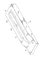
最初に図1を参照すると、以下「チャージ」「複合チャージ」「複合材部品チャージ」または「ストリンガチャージ」とも称される未硬化の複合樹脂部品20が、オートクレーブ26内に配置された硬化工具22上で硬化され、オートクレーブ26内では、オートクレーブ熱および圧力が複合チャージ20に加えられる。複合チャージ20は、1つまたは複数の内部空隙、閉じ込め領域もしくは封入領域、またはキャビティを含み、これらは、説明を容易にするために、以下まとめてキャビティ28と称する。硬化中にチャージ20に加えられるオートクレーブ圧力に反作用させるために、可撓性の膨張可能なブラダ30が、硬化サイクル前にキャビティ28内に配置される。可撓性の流体リザーバ32が、硬化工具22上に装着され、オートクレーブ26内の雰囲気に通気されない閉じたブラダシステム25を形成するようにブラダ30と結合される。換言すれば、ブラダ30と流体リザーバ32は、オートクレーブ26の内部雰囲気に直接さらされない閉じた流体系を形成する。真空バッグ24など可撓性のバッグが、硬化工具22を覆って配置され硬化工具22に対して封止され、複合チャージ20、ブラダ30、および流体リザーバ32を覆う。可撓性のバッグ24は、可撓性のバッグ24を真空排気するために適切な真空源64と結合されるように適合される。硬化中、ブラダ30は、流体リザーバ32から供給される実質的に非圧縮性の流体(図示せず)を使用して加圧される。
Referring first to FIG. 1, a
下記でより詳細に論ずるように、ブラダ30と流体リザーバ32が共に真空バッグ24の下に位置するので、ブラダ30は、オートクレーブ26の内部雰囲気に通気されない。すなわち、ブラダ30は非通気式である。それどころか、ブラダ30と流体リザーバ32の組合せは、真空バッグ24にかかるオートクレーブ気圧によって制御される閉じた非通気式ブラダシステム25を形成する。任意選択で、ブラダ30は、流体リザーバ32から供給される流体から、ブラダ30の実質的に完全な内部容積を分離する内部隔壁35を含むことができる。流体リザーバ32内の減圧により、ブラダ30は、部分的にわずかにつぶれることができ、それによりブラダ30が複合チャージ20内で「固定された状態」になることが防止され、硬化後の複合チャージ20からブラダ30を取り外すことが容易になる。
As will be discussed in more detail below, because the
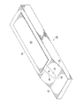
次に図2を参照すると、開示されている非通気式ブラダシステムおよび硬化方法を使用し、1つまたは複数の内部キャビティを有する、様々な幾何形状の様々な複合樹脂部品の任意のものを硬化させることができる。たとえば、限定することなしに、開示されているシステムおよび方法を、プリプレグのマルチプライレイアップを含むことができる繊維強化複合樹脂ストリンガ23の作製に使用することができる。ストリンガ23は、内部キャビティ31を形成するハットセクション27と、1対の横方向に延びるフランジセクション29と、硬化中にフランジセクション29と統合される実質的に平坦な外板セクション33とを含む。他のストリンガ幾何形状も可能である。
Referring now to FIG. 2, using the disclosed non-vented bladder system and curing method, cure any of a variety of composite resin parts of a variety of geometries having one or more internal cavities. Can be made. For example, without limitation, the disclosed systems and methods can be used to make fiber reinforced
図3〜10は、図2に示されているストリンガ23を硬化するための図1に示されている装置を準備する際の連続的な段階をそれぞれ示す。特に図3を参照すると、任意の好適な材料製の硬化工具22は、ハットセクション工具面32を画定する内部キャビティ28と、1対の横方向に延びるフランジセクション工具面34とを含む。工具面32、34は、ストリンガ23のそれぞれハットセクション27およびフランジセクション29の幾何形状にそれぞれ合致するように構成される。硬化工具22は、内部キャビティ28を囲む実質的に平坦な上部工具面36と、キャビティ28の一端にある面取り面38と、実質的に平坦な端部セクション40とを有する。内部キャビティ28の一端は、42で開いている。下記で論ずるように、硬化工具22を使用し、複合ストリンガチャージを組み立て、組み立てられたチャージをオートクレーブ26(図1)内で硬化することができる。図の硬化工具22はストリンガ23の特徴に合致するように適合された幾何形状を有するが、開示されている非通気式ブラダシステム25は、応用例、および硬化しようとする特定の複合材部品チャージに応じて、任意の様々な他の幾何形状を有する硬化工具と共に使用されてもよいことを理解されたい。
3-10 show the successive steps in preparing the apparatus shown in FIG. 1 for curing the
図4を参照すると、複合ストリンガチャージ20が硬化工具22上に配置されている。ストリンガチャージ20は、キャビティ28を満たし工具面32(図3)と係合するハット20aと、工具面34とそれぞれ係合する1対の横方向に延びるフランジ20bとを備える。ストリンガチャージ20は、別個のレイアップ工具(図示せず)上でレイアップし、次いで硬化工具22に移してもよく、あるいは部品チャージの幾何形状に応じて、ストリンガを硬化工具22上で直接レイアップすることも可能となり得る。
Referring to FIG. 4, a
次に図5を参照すると、ストリンガチャージ20が硬化工具22内に配置された後で、硬化サイクル中に加えられるオートクレーブ圧力に反作用させるために、可撓性のブラダ30がストリンガチャージ20のキャビティ28(図4)内に配置される。ブラダ30は、たとえば限定しないがエラストマーなど、任意の好適な材料から形成することができる。ブラダ30には、設置される前に離型剤を付着しておき、硬化に続いてキャビティ28からブラダを後で取り外すのを容易にすることができる。ブラダ30は、下記で論ずるように、図1に示されている流体リザーバ32と結合されるように適合されたブラダ通気穴44を含む。この例では、ブラダ30はキャビティ28の幾何形状に実質的に合致するように構成されており、硬化工具22の平坦な工具表面36と実質的に同一平面である実質的に平坦な上部表面30aを有する。
Referring now to FIG. 5, after the
次に図6を参照すると、図5に示されているようにブラダ30が設置された後で、実質的に平坦な複合外板チャージ46が硬化工具22上に配置され、ブラダ30を覆い隠し、ストリンガチャージ20のフランジ20b(図5)および平坦な工具表面36と対面接触する。次に、図7に示されているように、硬化プロセス中に外板チャージ46の上に実質的に均一な圧力を加えるために、平坦な複合外板チャージ46を覆って、当て板48を設置することができる。また、図7には示されていないが、応用例に応じて、ピールプライ、離型フィルム、および/もしくはブリーザ、または他の構成部品を当て板48と共に設置してもよい。図8に示されているように、工具22を真空バギングするための準備の際に、好適なシーラントテープ50または他の好適なシーラントを硬化工具22の周部に付着することができる。この時点で、真空プローブベース52を、硬化工具22の平坦な端部セクション40に付着することができる。
Referring now to FIG. 6, after the
次に、図9に示されているように、可撓性の流体リザーバ32がブラダ30に取り付けられ、その結果、望むなら、ブラダ30および流体リザーバ32を、単一のアセンブリとして設置し取り外すことができる。流体リザーバ32は、ブラダ30内の通気穴44(図8)と結合され、ブラダ30が複合外板チャージキャビティ28内で定位置にあるとき硬化工具22の面取り面38上で支持される。流体リザーバ32は、ブラダ30に永続的に取り付けられ、ブラダ30に対して封止されてもよく、したがって、硬化プロセスの準備の際にブラダ30が複合チャージ20内に設置されるたびに、ブラダ30を圧力源に再接続する必要がなくなる。また、この構成は、ブラダが複合チャージ20内に設置されるたびに、シーラントを通気穴44周りに配置する必要をなくする。流体リザーバ32は、限定しないがエラストマーなど、任意の好適な材料から形成することができる。真空プローブ54が、真空プローブベース52上に装着され、硬化サイクル中に真空バッグ24を真空排気するために真空源(図示せず)と結合されるように適合される。
Next, as shown in FIG. 9, a
次に図10を参照すると、流体リザーバ32は、概して矩形または方形の断面形状を有することができ、流体リザーバ32に外部圧力が加えられたとき破線32bによって示されているように下向きに塑性変形することができる、可撓性である側部32aを有する。流体リザーバ32の一部分32bは、ブラダ30の一端に対面接触して取り付けられており、ブラダ30内の通気穴44と位置合わせされ結合され、流体が流体リザーバ32とブラダ30の間を流れることを可能にする流体出口41を含む。他の実施形態では、流体リザーバ32は、異なる形状を有することができ、ブラダ30に取り付けられても取り付けられなくてもよい。図9に示されている流体リザーバ32の設置に続いて、真空バッグ24と称することもある、ポリエステルまたはナイロンなど任意の好適な材料から形成された可撓性のバッグ24が、工具22を覆って設置され、流体リザーバ32、ストリンガチャージ20、46、およびブラダ30を覆う。真空バッグ24は、流体リザーバ32と対面接触する。真空バッグ24は、封止用テープ50または他の好適なシーラントを使用して、硬化工具22の周縁に対して、また真空プローブ54周りで封止される。真空バッグ24を真空排気することにより、真空バッグ24が流体リザーバ32の側部と対面接触で引き下げられ、オートクレーブ圧力PAを流体リザーバ32に加えることができる。
Referring now to FIG. 10, the
任意選択で、流体リザーバ32は、硬化サイクルに続いて真空バッグ24が取り外された後で真空源(図示せず)と結合されるように適合された真空ポート60を含むことができる。真空ポート60は、硬化中、真空バッグ24の下で閉じられ封止されているが、硬化が完了し、真空バッグが取り外された後で、流体リザーバ32の内部容積56を真空源に接続することを可能にするバルブまたは他の装置(図示せず)を含む。このように流体リザーバ32を真空源に結合することにより、流体リザーバ32内の流体圧力が解放され、これによりブラダ30内の圧力が低下し、ブラダ30がわずかに収縮する、またはつぶれることを可能にする。このようにブラダ30が収縮することにより、ブラダ30の最大断面寸法(図示せず)が、硬化後のストリンガからブラダ30を取り外すことを可能にするのに十分な量だけ減少する。
Optionally, the
オートクレーブ内で実施される硬化中、オートクレーブ圧力PAが真空バッグ24を硬化工具22に押し付け、それにより複合チャージ20を押し固め、一方、流体リザーバ32に圧力を加える。流体リザーバ32に加えられたオートクレーブ圧力PAにより、流体リザーバ32の内部容積56から流体が流れ(45)、ブラダ通気穴44を通ってブラダ30に入り、それによりブラダ30が内部加圧される。ブラダ30のこの加圧により、複合チャージ20に加えられたオートクレーブ圧力PAに反作用する力55が複合チャージ20に加えられる。硬化が完了したとき、オートクレーブ圧力PAが真空バッグ22から除去され、したがって流体リザーバ32から除去される。その結果として生じる流体リザーバ32内の流体圧力の低下により、流体はブラダ58から通気穴44を通って流体リザーバ32内に流れて戻ることが可能になる。
During the curing is carried out in an autoclave, the autoclave pressure P A is pressed against the
前述のように、流体リザーバ32は、ブラダ30に対して永続的に封止されてもよく、したがって、ブラダ30が複合チャージ20内に設置されるたびに通気穴44(図8)周りにシーラントを配置する必要がなくなる。したがって、流体リザーバ32をブラダ30に対して永続的に封止することにより、通気穴44周りの、複合チャージ20内への漏れをなくすることができる。ブラダ30または流体リザーバ32のどちらかに漏れがある場合、複合チャージ20内への流体の漏れは、ブラダ30と流体リザーバ32の総容積に限定される。なぜなら、ブラダシステム25(図1)が閉じた系であり、オートクレーブからの空気が複合チャージキャビティ28(図4)内に入ることができないからである。
As previously described, the
開示されている非通気式ブラダシステムの代替の実施形態が、図11および図12に示されている。この実施形態では、ブラダ30は、ブラダ30の内側チャンバ65を、流体リザーバ32によって供給される流体から分離する内部隔壁35を含む。隔壁35は、可撓性の材料製であり、ブラダ30と一体に形成されてもよい。ブラダチャンバ65は、比較的低いCTE(熱膨張率)と、ブラダ30に所望のレベルの剛性を与えるように選択された密度とを有する流動性の充填材料66で満たされる。隔壁35の一方の側部75が、流体リザーバ32によって供給される流体にさらされる。オートクレーブ圧力PAによってブラダ30に押し付けられたリザーバ56からの流体が、隔壁35に対して流体圧力PF(図12)を働かせ、隔壁35を、図12に示されている位置35aに内向きに撓ませる。充填材料66の加圧により、外向きの圧力68が複合チャージ20に対して働く。
An alternative embodiment of the disclosed non-ventilated bladder system is shown in FIGS. In this embodiment, the
次に図13を参照すると、上述の非通気式ブラダシステム25内に漏れがある場合、ブラダシステム25は真空バッグ24の下で封止されているので、オートクレーブ26(図1)内の空気の体積が複合チャージ20に達しない。それどころか、ブラダ30または流体リザーバ32のどちらかに漏れがある場合(図10〜12)に複合チャージ20に達する可能性がある流体の総量は、流体リザーバ内側容積56にブラダチャンバ容積65を加算したものに限定される。
Referring now to FIG. 13, if there is a leak in the
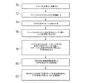
次に、上述の非通気式ブラダシステム25を使用してオートクレーブ硬化するための方法のステップを広く例示する図14に注目する。ステップ70で開始して、複合樹脂チャージ20が、硬化工具とすることができる好適な工具上に配置される。72では、可撓性の膨張可能なブラダ30が、チャージ20の内部キャビティ28内に設置される。74では、可撓性のブラダ30が、一定量の流体を収容する可撓性の流体リザーバ32と結合される。76では、流体リザーバ32と共に複合チャージ20が、真空バッグなど可撓性のバッグ24で覆われ、次いでバッグ24が硬化工具22に対して封止される。78では、流体リザーバ32を圧縮し、リザーバ32から流体をブラダ30内に押し込むために、オートクレーブ圧力PAがバッグ24に加えられ、それにより、オートクレーブ圧力によって複合チャージ20に加えられる力に反作用するようにブラダ30を加圧する。任意選択で、ステップ80では、ブラダ30内の内部隔壁35を使用し、流体リザーバ32によって生成される流体圧力を使用してブラダ30に圧力を伝達してもよい。また、任意選択で、ステップ82では、硬化および真空バッグ24の取外しに続いて、流体リザーバ32を好適な真空源と結合することによって、流体リザーバ32内の圧力を解放し、ブラダ取外しの助けとすることができる。
Attention is now directed to FIG. 14, which broadly illustrates the steps of a method for autoclave curing using the
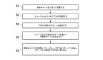
複合材部品チャージ20を硬化する代替の方法が、図15に示されている。84では、複合材部品チャージ20が工具22上に配置され、86では、ブラダ30が複合材部品チャージ20のキャビティ28内に設置される。ブラダ30は、ステップ88で流体のリザーバ32と結合される。次に、ステップ90に示されているように、可撓性のバッグ24が複合材部品チャージ20および流体のリザーバ32を覆って封止される。ステップ92では、可撓性のバッグ24を使用し、オートクレーブ圧力を流体のリザーバ32に伝達し、リザーバ32から流体をブラダ30内に押し込む。
An alternative method of curing the
本開示の実施形態は、様々な潜在的な応用例、たとえば航空宇宙、船舶、自動車応用例を含めて特に輸送産業、および複合材部品のオートクレーブ硬化を使用することができる他の応用例において使用される可能性がある。したがって、次に図16および図17を参照すると、本開示の実施形態は、図16に示されている航空機製造および整備方法94、ならびに図16に示されている航空機96の状況において使用することができる。開示されている実施形態の航空機応用例は、たとえば限定しないが、いくつか例を挙げれば、ビーム、スパー、およびストリンガなど、限定しないがスティフナの硬化を含むことができる。生産前段階中には、例示的な方法94は、航空機96の仕様および設計98と、材料調達100とを含むことができる。生産中には、航空機96の構成部品およびサブアセンブリ製造102ならびにシステム統合104が行われる。その後で、航空機96は、運用に移す(108)ために検証および出荷106を受けることができる。顧客によって運用されている間、航空機96には、日常の保守および整備110が予定されており、やはり改修、再構成、リハービッシュなどを含む可能性がある。
Embodiments of the present disclosure are used in a variety of potential applications, particularly in the transportation industry, including aerospace, marine, automotive applications, and other applications where autoclaving of composite parts can be used. There is a possibility that. Accordingly, with reference now to FIGS. 16 and 17, embodiments of the present disclosure are to be used in the aircraft manufacturing and
方法94のプロセスのそれぞれは、システムインテグレータ、第三者、および/またはオペレータ(たとえば顧客)によって実行または実施されてもよい。この説明では、システムインテグレータは、限定しないが任意の数の航空機製造者および主要システム下請け業者を含むことができ、第三者は、限定しないが任意の数のベンダ、下請け業者、および供給者を含むことができ、オペレータは、航空会社、リース会社、軍、整備企業などとすることができる。
Each of the processes of
図17に示されているように、例示的な方法94によって生産された航空機96は、機体112を複数のシステム114およびインテリア116と共に含むことができる。高レベルシステム114の例は、推進システム118、電気システム120、油圧システム122、および環境システム124の1つまたは複数を含む。任意の数の他のシステムが含まれてもよい。航空宇宙の例が示されているが、本開示の原理は、船舶工業および自動車工業など、他の産業に応用することができる。
As shown in FIG. 17, an
本明細書に含まれているシステムおよび方法は、生産および整備方法94の段階の任意の1つまたは複数の間に使用することができる。たとえば、生産プロセス102に対応する構成部品またはサブアセンブリは、航空機96が運用されている間に生産される構成部品またはサブアセンブリと同様にして作製または製造されてもよい。また、1つまたは複数の装置実施形態、方法実施形態、またはそれらの組合せは、生産段階102、104中に、たとえば航空機96の組立てを実質的に速めること、または航空機96のコストを削減することによって役立たせることができる。同様に、装置実施形態、方法実施形態、またはそれらの組合せの1つまたは複数は、航空機96が運用されている間に、たとえば限定しないが保守および整備110に役立たせることができる。
The systems and methods included herein can be used during any one or more of the stages of production and
様々な有利な実施形態の説明は、例示および説明のために提供されており、網羅的なものとすることも、開示されている形態にある実施形態に限定することも意図していない。多数の修正形態および変形形態が当業者には明らかになるであろう。さらに、異なる有利な実施形態は、他の有利な実施形態に比べて、異なる利点を提供することがある。選択された1つまたは複数の実施形態は、実施形態の原理、実用的な応用例について最もよく説明するために、また、企図されている特定の仕様に適した様々な修正形態と共に様々な実施形態について、当業者が本開示を理解することができるように、選択され述べられている。 The description of various advantageous embodiments is provided for purposes of illustration and description, and is not intended to be exhaustive or limited to the embodiments in the form disclosed. Many modifications and variations will be apparent to practitioners skilled in this art. Furthermore, different advantageous embodiments may provide different advantages compared to other advantageous embodiments. The selected embodiment or embodiments may be implemented in various ways to best illustrate the principles of the embodiments, practical applications, and with various modifications appropriate to the particular specification contemplated. The forms have been chosen and described so that others skilled in the art can appreciate the present disclosure.
20 チャージ、複合ストリンガチャージ、複合チャージ、複合樹脂チャージ、複合樹脂部品
20a ハット
20b フランジ
22 硬化工具
23 ストリンガ
24 可撓性のバッグ、真空バッグ
25 非通気式ブラダシステム
26 オートクレーブ
27 ハットセクション
28 キャビティ
29 フランジセクション
30 ブラダ
30a 上部表面
31 内部キャビティ
32 ハットセクション工具面、流体リザーバ
32a 側部
32b 破線
33 外板セクション
34 フランジセクション工具面
35 内部隔壁
35a 位置
36 工具表面、上部工具面
38 面取り面
40 端部セクション
41 流体出口
44 ブラダ通気穴
46 複合外板チャージ
48 当て板
50 シーラントテープ、封止用テープ
52 真空プローブベース
54 真空プローブ
55 力
56 リザーバ、内部容積
58 ブラダ
60 真空ポート
64 真空源
65 内側チャンバ
66 充填材料
68 圧力
75 側部
96 航空機
112 機体
114 システム
116 インテリア
118 推進システム
120 電気システム
122 油圧システム
124 環境システム
PA オートクレーブ圧力
PF 流体圧力
20 charge, composite stringer charge, composite charge, composite resin charge,
Claims (14)
前記硬化中に前記複合チャージ(20)に圧力を加えるために前記キャビティ(28)内に配置されるように適合された可撓性のブラダ(30)と、
前記ブラダ(30)を加圧するための流体のリザーバ(32)であって、前記リザーバ(32)と前記ブラダ(30)が閉じた系(25)内で共に結合されている、リザーバ(32)と、
前記可撓性のブラダ(30)および前記流体リザーバ(32)を覆って封止された可撓性のバッグ(24)であって、前記流体リザーバ(32)と面と面との接触をしている可撓性のバッグ(24)と、
を備える装置。 An apparatus for use in autoclave curing of a composite charge (20) having an internal cavity (28) comprising:
A flexible bladder (30) adapted to be placed in the cavity (28) to apply pressure to the composite charge (20) during the curing;
A reservoir (32) of fluid for pressurizing the bladder (30), wherein the reservoir (32) and the bladder (30) are joined together in a closed system (25). When,
A flexible bag (24) sealed over the flexible bladder (30) and the fluid reservoir (32), wherein the fluid reservoir (32) is in surface-to-surface contact . A flexible bag (24),
A device comprising:
前記流体リザーバ(32)が前記硬化工具(22)上に位置し、前記可撓性のバッグ(24)が前記硬化工具(22)に封止されている、請求項1または2に記載の装置。 Further comprising a curing tool (22) adapted to be disposed on said composite charge (20);
The apparatus according to claim 1 or 2, wherein the fluid reservoir (32) is located on the curing tool (22) and the flexible bag (24) is sealed to the curing tool (22). .
前記流体リザーバ(32)の一部分が、前記ブラダ(30)に取り付けられており、前記ブラダ(30)内の前記通気穴(44)と結合された流体出口(41)を含んでいる、請求項1から4のいずれか一項に記載の装置。 The bladder (30) includes a vent (44);
A portion of the fluid reservoir (32) is attached to the bladder (30) and includes a fluid outlet (41) coupled to the vent (44) in the bladder (30). The apparatus according to any one of 1 to 4.
前記ブラダ(30)内で内側チャンバ(65)を形成する隔壁(35)と、
前記ブラダ(30)が前記流体リザーバ(32)からの流体によって加圧されたとき前記ブラダ(30)を剛性化するのに十分な密度を有する、前記内側チャンバ(65)を満たす充填材料(66)と
を含んでいる、請求項1から6のいずれか一項に記載の装置。 The bladder (30)
A septum (35) forming an inner chamber (65) in the bladder (30);
Filling material (66) filling the inner chamber (65) having a density sufficient to stiffen the bladder (30) when the bladder (30) is pressurized with fluid from the fluid reservoir (32). The device according to any one of claims 1 to 6, comprising:
前記可撓性の側部が、前記流体リザーバ(32)が前記ブラダ(30)を加圧したとき前記充填材料(66)に圧力を加えるように撓む、請求項7に記載の装置。 The septum (35) includes a flexible side exposed to fluid from the fluid reservoir (32);
The apparatus of claim 7, wherein the flexible side deflects to apply pressure to the filler material (66) when the fluid reservoir (32) pressurizes the bladder (30).
前記複合チャージ(20)を工具(22)上に配置すること(70)、
前記キャビティ(28)内にブラダ(30)を設置すること(72)、
前記ブラダ(30)を流体のリザーバ(32)と結合すること(74)、
前記複合チャージ(20)および前記リザーバ(32)を覆って、前記流体リザーバ(32)と面と面との接触をさせて可撓性のバッグ(24)を封止すること(76)、ならびに
前記可撓性のバッグ(24)を使用してオートクレーブ圧力を前記リザーバ(32)に伝達し、前記リザーバ(32)から流体を前記ブラダ(30)内に押し込むこと(78)
を含む方法。 A method of autoclave curing a composite charge (20) having an internal cavity (28) comprising:
Placing (70) the composite charge (20) on the tool (22);
Installing a bladder (30) in the cavity (28) (72);
Coupling the bladder (30) with a fluid reservoir (32) (74);
Covering the composite charge (20) and the reservoir (32) to bring the fluid reservoir (32) into surface-to-surface contact to seal a flexible bag (24) (76); and Using the flexible bag (24) to transmit autoclave pressure to the reservoir (32) and forcing fluid from the reservoir (32) into the bladder (30) (78)
Including methods.
前記ブラダ(30)内に隔壁(35)を配置すること(80)によって前記充填材料(66)を前記流体から分離すること
をさらに含む、請求項9から11のいずれか一項に記載の方法。 Stiffening the bladder (30) by filling the bladder (30) with a filling material (66), and placing a partition wall (35) in the bladder (30) (80) The method according to any one of claims 9 to 11, further comprising separating 66) from the fluid.
前記可撓性のバッグ(24)が取り外された(82)後で、真空源(64)に対して前記リザーバ(32)のポートを開けることによって前記ブラダ(30)内の圧力を解放すること
をさらに含む、請求項9から13のいずれか一項に記載の方法。 Removing the flexible bag (24) from the composite charge (20) and the reservoir (32) after the composite charge (20) has cured; and removing the flexible bag (24). 14. The method of claim 9, further comprising releasing the pressure in the bladder (30) by opening a port of the reservoir (32) with respect to a vacuum source (64) after The method according to one item.
Applications Claiming Priority (2)
| Application Number | Priority Date | Filing Date | Title |
|---|---|---|---|
| US13/491,698 | 2012-06-08 | ||
| US13/491,698 US9381704B2 (en) | 2012-06-08 | 2012-06-08 | Non-vented bladder system for curing composite parts |
Publications (3)
| Publication Number | Publication Date |
|---|---|
| JP2014012399A JP2014012399A (en) | 2014-01-23 |
| JP2014012399A5 JP2014012399A5 (en) | 2016-07-07 |
| JP6170346B2 true JP6170346B2 (en) | 2017-07-26 |
Family
ID=48468178
Family Applications (1)
| Application Number | Title | Priority Date | Filing Date |
|---|---|---|---|
| JP2013119019A Active JP6170346B2 (en) | 2012-06-08 | 2013-06-05 | Non-ventilated bladder system for curing composite parts |
Country Status (9)
| Country | Link |
|---|---|
| US (2) | US9381704B2 (en) |
| EP (1) | EP2671709B1 (en) |
| JP (1) | JP6170346B2 (en) |
| KR (1) | KR102052923B1 (en) |
| CN (1) | CN103481433B (en) |
| BR (1) | BR102013014257B1 (en) |
| CA (1) | CA2812376C (en) |
| ES (1) | ES2564140T3 (en) |
| RU (1) | RU2660136C9 (en) |
Families Citing this family (16)
| Publication number | Priority date | Publication date | Assignee | Title |
|---|---|---|---|---|
| US9381704B2 (en) | 2012-06-08 | 2016-07-05 | The Boeing Company | Non-vented bladder system for curing composite parts |
| US9399509B2 (en) * | 2014-04-10 | 2016-07-26 | The Boeing Company | Vent stringer fitting |
| US9914244B2 (en) * | 2014-08-04 | 2018-03-13 | The Boeing Company | Bladder system for curing composite parts |
| US9399510B2 (en) * | 2014-08-20 | 2016-07-26 | The Boeing Company | Hat stringer closeout fitting and method of making same |
| US10144185B2 (en) * | 2015-04-01 | 2018-12-04 | The Boeing Company | Method and apparatus for high-temperature post-curing of UV-cured photopolymers |
| US10315366B2 (en) | 2015-05-11 | 2019-06-11 | Gulfstream Aerospace Corporation | Apparatuses and methods for making reinforcement structures |
| US10843416B2 (en) | 2015-05-11 | 2020-11-24 | Gulfstream Aerospace Corporation | Composite reinforcement structures and aircraft assemblies comprising composite reinforcement structures |
| US20160339682A1 (en) | 2015-05-18 | 2016-11-24 | The Boeing Company | Bladder System for Curing Composite Parts |
| US10293552B2 (en) | 2015-11-17 | 2019-05-21 | The Boeing Company | Heat shrinkable film tube and method for manufacturing hollow composite parts |
| US10639855B2 (en) * | 2017-02-07 | 2020-05-05 | General Electric Company | Applicator systems for applying pressure to a structure |
| US10751955B2 (en) | 2017-04-10 | 2020-08-25 | The Boeing Company | Unitized composite structure manufacturing system |
| US10710319B2 (en) | 2017-08-02 | 2020-07-14 | The Boeing Company | Controlling application of forces to different portions of object surface using bladder |
| US10710320B2 (en) * | 2017-08-02 | 2020-07-14 | The Boeing Company | Controlling application of forces to different portions of object surface using flexible wall |
| JP6667055B2 (en) | 2017-09-07 | 2020-03-18 | 川崎重工業株式会社 | Mold for producing composite material molded article and method for producing composite material molded article |
| CN108162433B (en) * | 2018-03-01 | 2020-04-10 | 江苏金风科技有限公司 | Vacuum infusion auxiliary device and vacuum infusion process |
| GB2575102A (en) * | 2018-06-29 | 2020-01-01 | Airbus Operations Ltd | Duct stringer with bulkhead |
Family Cites Families (19)
| Publication number | Priority date | Publication date | Assignee | Title |
|---|---|---|---|---|
| US4178406A (en) * | 1977-12-29 | 1979-12-11 | Rohm And Haas Company | Three-layered fiberglass construction |
| US4222721A (en) * | 1978-09-08 | 1980-09-16 | The Firestone Tire & Rubber Company | Apparatus for curing tires and the like |
| US5484277A (en) | 1989-12-26 | 1996-01-16 | Mcdonnell Douglas Corporation | Mandreless molding system |
| SU1785910A1 (en) * | 1990-02-19 | 1993-01-07 | B Yuzhn K | Method and device for producing composite laminated structures |
| US5366684A (en) * | 1992-12-31 | 1994-11-22 | Grumman Aerospace Corporation | Molding composite method using an inflatable bladder pressurized in an autoclave |
| EP1365908B1 (en) * | 2001-01-25 | 2014-09-10 | Quickstep Technologies Pty, Ltd | System and method for producing a composite or bonded metal component |
| WO2003101708A1 (en) * | 2002-05-29 | 2003-12-11 | The Boeing Company | Controlled atmospheric pressure resin infusion process |
| US7335012B2 (en) * | 2004-12-22 | 2008-02-26 | General Electric Company | Apparatus for fabricating reinforced composite materials |
| US8834782B2 (en) * | 2007-08-07 | 2014-09-16 | William L. Rodman | Composite structures and methods of making same |
| US9327467B2 (en) | 2008-07-10 | 2016-05-03 | The Boeing Company | Composite mandrel for autoclave curing applications |
| US9238335B2 (en) | 2008-07-10 | 2016-01-19 | The Boeing Company | Mandrel for autoclave curing applications |
| US8652371B2 (en) * | 2008-11-20 | 2014-02-18 | Cytec Technology Corp. | Constant pressure infusion process for resin transfer molding |
| JP5313646B2 (en) * | 2008-12-04 | 2013-10-09 | 株式会社ニューケミカル | Manufacturing method of fiber reinforced resin molded product |
| US8293051B2 (en) | 2008-12-10 | 2012-10-23 | The Boeing Company | Method for producing composite laminates using a collapsible mandrel |
| US20100186899A1 (en) * | 2009-01-15 | 2010-07-29 | Airtech International, Inc. | Thermoplastic mandrels for composite fabrication |
| US8074694B2 (en) | 2009-05-28 | 2011-12-13 | The Boeing Company | Stringer transition method |
| JP5430424B2 (en) * | 2010-01-28 | 2014-02-26 | 本田技研工業株式会社 | Method for forming aircraft wing structure |
| US8430984B2 (en) * | 2010-05-11 | 2013-04-30 | The Boeing Company | Collapsible mandrel employing reinforced fluoroelastomeric bladder |
| US9381704B2 (en) | 2012-06-08 | 2016-07-05 | The Boeing Company | Non-vented bladder system for curing composite parts |
-
2012
- 2012-06-08 US US13/491,698 patent/US9381704B2/en active Active
-
2013
- 2013-04-09 CA CA2812376A patent/CA2812376C/en active Active
- 2013-04-18 KR KR1020130042634A patent/KR102052923B1/en active IP Right Grant
- 2013-05-23 ES ES13169023.2T patent/ES2564140T3/en active Active
- 2013-05-23 EP EP13169023.2A patent/EP2671709B1/en active Active
- 2013-06-04 RU RU2013125720A patent/RU2660136C9/en active
- 2013-06-05 JP JP2013119019A patent/JP6170346B2/en active Active
- 2013-06-07 BR BR102013014257-3A patent/BR102013014257B1/en active IP Right Grant
- 2013-06-07 CN CN201310224985.1A patent/CN103481433B/en active Active
-
2016
- 2016-07-01 US US15/200,330 patent/US10040256B2/en active Active
Also Published As
| Publication number | Publication date |
|---|---|
| BR102013014257B1 (en) | 2020-12-01 |
| BR102013014257A2 (en) | 2015-06-23 |
| RU2013125720A (en) | 2014-12-10 |
| US10040256B2 (en) | 2018-08-07 |
| CA2812376A1 (en) | 2013-12-08 |
| CN103481433B (en) | 2017-03-01 |
| RU2660136C9 (en) | 2018-11-29 |
| US20160311179A1 (en) | 2016-10-27 |
| RU2660136C2 (en) | 2018-07-05 |
| KR20130138099A (en) | 2013-12-18 |
| US20130327477A1 (en) | 2013-12-12 |
| ES2564140T3 (en) | 2016-03-18 |
| EP2671709B1 (en) | 2016-02-03 |
| CA2812376C (en) | 2015-06-23 |
| KR102052923B1 (en) | 2019-12-11 |
| JP2014012399A (en) | 2014-01-23 |
| EP2671709A1 (en) | 2013-12-11 |
| CN103481433A (en) | 2014-01-01 |
| US9381704B2 (en) | 2016-07-05 |
Similar Documents
| Publication | Publication Date | Title |
|---|---|---|
| JP6170346B2 (en) | Non-ventilated bladder system for curing composite parts | |
| US8333864B2 (en) | Compaction of prepreg plies on composite laminate structures | |
| EP2512783B1 (en) | Double vacuum cure processing of composite parts | |
| JP6181190B2 (en) | Method and apparatus for co-curing composite skin and composite stiffener in an autoclave | |
| KR20170044027A (en) | Method of curing a composite article using differential vacuum | |
| JP6594674B2 (en) | Air bag system for curing composite parts | |
| JP6479421B2 (en) | Tools and methods for forming contoured composite structures with shape memory alloys | |
| US20220152956A1 (en) | Caul Plate System for Aircraft Fabrication | |
| US11034431B2 (en) | Composite article with fly-away bag carrier | |
| US20220332060A1 (en) | Apparatus and method for processing a composite structure | |
| NL2027386B1 (en) | Caul plate system for aircraft fabrication |
Legal Events
| Date | Code | Title | Description |
|---|---|---|---|
| A521 | Request for written amendment filed |
Free format text: JAPANESE INTERMEDIATE CODE: A523 Effective date: 20160523 |
|
| A621 | Written request for application examination |
Free format text: JAPANESE INTERMEDIATE CODE: A621 Effective date: 20160523 |
|
| A977 | Report on retrieval |
Free format text: JAPANESE INTERMEDIATE CODE: A971007 Effective date: 20170221 |
|
| A131 | Notification of reasons for refusal |
Free format text: JAPANESE INTERMEDIATE CODE: A131 Effective date: 20170228 |
|
| A521 | Request for written amendment filed |
Free format text: JAPANESE INTERMEDIATE CODE: A523 Effective date: 20170523 |
|
| TRDD | Decision of grant or rejection written | ||
| A01 | Written decision to grant a patent or to grant a registration (utility model) |
Free format text: JAPANESE INTERMEDIATE CODE: A01 Effective date: 20170606 |
|
| A61 | First payment of annual fees (during grant procedure) |
Free format text: JAPANESE INTERMEDIATE CODE: A61 Effective date: 20170630 |
|
| R150 | Certificate of patent or registration of utility model |
Ref document number: 6170346 Country of ref document: JP Free format text: JAPANESE INTERMEDIATE CODE: R150 |
|
| R250 | Receipt of annual fees |
Free format text: JAPANESE INTERMEDIATE CODE: R250 |
|
| R250 | Receipt of annual fees |
Free format text: JAPANESE INTERMEDIATE CODE: R250 |
|
| R250 | Receipt of annual fees |
Free format text: JAPANESE INTERMEDIATE CODE: R250 |
|
| R250 | Receipt of annual fees |
Free format text: JAPANESE INTERMEDIATE CODE: R250 |