BR102013014257B1 - apparatus and method for use in autoclave curing of a composite load - Google Patents
apparatus and method for use in autoclave curing of a composite load Download PDFInfo
- Publication number
- BR102013014257B1 BR102013014257B1 BR102013014257-3A BR102013014257A BR102013014257B1 BR 102013014257 B1 BR102013014257 B1 BR 102013014257B1 BR 102013014257 A BR102013014257 A BR 102013014257A BR 102013014257 B1 BR102013014257 B1 BR 102013014257B1
- Authority
- BR
- Brazil
- Prior art keywords
- bladder
- reservoir
- fluid
- fluid reservoir
- autoclave
- Prior art date
Links
Images


Classifications
-
- B—PERFORMING OPERATIONS; TRANSPORTING
- B29—WORKING OF PLASTICS; WORKING OF SUBSTANCES IN A PLASTIC STATE IN GENERAL
- B29C—SHAPING OR JOINING OF PLASTICS; SHAPING OF MATERIAL IN A PLASTIC STATE, NOT OTHERWISE PROVIDED FOR; AFTER-TREATMENT OF THE SHAPED PRODUCTS, e.g. REPAIRING
- B29C35/00—Heating, cooling or curing, e.g. crosslinking or vulcanising; Apparatus therefor
- B29C35/02—Heating or curing, e.g. crosslinking or vulcanizing during moulding, e.g. in a mould
- B29C35/04—Heating or curing, e.g. crosslinking or vulcanizing during moulding, e.g. in a mould using liquids, gas or steam
-
- B—PERFORMING OPERATIONS; TRANSPORTING
- B29—WORKING OF PLASTICS; WORKING OF SUBSTANCES IN A PLASTIC STATE IN GENERAL
- B29C—SHAPING OR JOINING OF PLASTICS; SHAPING OF MATERIAL IN A PLASTIC STATE, NOT OTHERWISE PROVIDED FOR; AFTER-TREATMENT OF THE SHAPED PRODUCTS, e.g. REPAIRING
- B29C35/00—Heating, cooling or curing, e.g. crosslinking or vulcanising; Apparatus therefor
- B29C35/02—Heating or curing, e.g. crosslinking or vulcanizing during moulding, e.g. in a mould
-
- B—PERFORMING OPERATIONS; TRANSPORTING
- B29—WORKING OF PLASTICS; WORKING OF SUBSTANCES IN A PLASTIC STATE IN GENERAL
- B29C—SHAPING OR JOINING OF PLASTICS; SHAPING OF MATERIAL IN A PLASTIC STATE, NOT OTHERWISE PROVIDED FOR; AFTER-TREATMENT OF THE SHAPED PRODUCTS, e.g. REPAIRING
- B29C70/00—Shaping composites, i.e. plastics material comprising reinforcements, fillers or preformed parts, e.g. inserts
- B29C70/04—Shaping composites, i.e. plastics material comprising reinforcements, fillers or preformed parts, e.g. inserts comprising reinforcements only, e.g. self-reinforcing plastics
- B29C70/28—Shaping operations therefor
- B29C70/40—Shaping or impregnating by compression not applied
- B29C70/42—Shaping or impregnating by compression not applied for producing articles of definite length, i.e. discrete articles
- B29C70/44—Shaping or impregnating by compression not applied for producing articles of definite length, i.e. discrete articles using isostatic pressure, e.g. pressure difference-moulding, vacuum bag-moulding, autoclave-moulding or expanding rubber-moulding
- B29C70/446—Moulding structures having an axis of symmetry or at least one channel, e.g. tubular structures, frames
-
- B—PERFORMING OPERATIONS; TRANSPORTING
- B29—WORKING OF PLASTICS; WORKING OF SUBSTANCES IN A PLASTIC STATE IN GENERAL
- B29C—SHAPING OR JOINING OF PLASTICS; SHAPING OF MATERIAL IN A PLASTIC STATE, NOT OTHERWISE PROVIDED FOR; AFTER-TREATMENT OF THE SHAPED PRODUCTS, e.g. REPAIRING
- B29C33/00—Moulds or cores; Details thereof or accessories therefor
- B29C33/10—Moulds or cores; Details thereof or accessories therefor with incorporated venting means
-
- B—PERFORMING OPERATIONS; TRANSPORTING
- B29—WORKING OF PLASTICS; WORKING OF SUBSTANCES IN A PLASTIC STATE IN GENERAL
- B29C—SHAPING OR JOINING OF PLASTICS; SHAPING OF MATERIAL IN A PLASTIC STATE, NOT OTHERWISE PROVIDED FOR; AFTER-TREATMENT OF THE SHAPED PRODUCTS, e.g. REPAIRING
- B29C33/00—Moulds or cores; Details thereof or accessories therefor
- B29C33/38—Moulds or cores; Details thereof or accessories therefor characterised by the material or the manufacturing process
- B29C33/40—Plastics, e.g. foam or rubber
- B29C33/405—Elastomers, e.g. rubber
-
- B—PERFORMING OPERATIONS; TRANSPORTING
- B29—WORKING OF PLASTICS; WORKING OF SUBSTANCES IN A PLASTIC STATE IN GENERAL
- B29C—SHAPING OR JOINING OF PLASTICS; SHAPING OF MATERIAL IN A PLASTIC STATE, NOT OTHERWISE PROVIDED FOR; AFTER-TREATMENT OF THE SHAPED PRODUCTS, e.g. REPAIRING
- B29C33/00—Moulds or cores; Details thereof or accessories therefor
- B29C33/44—Moulds or cores; Details thereof or accessories therefor with means for, or specially constructed to facilitate, the removal of articles, e.g. of undercut articles
- B29C33/48—Moulds or cores; Details thereof or accessories therefor with means for, or specially constructed to facilitate, the removal of articles, e.g. of undercut articles with means for collapsing or disassembling
- B29C33/485—Moulds or cores; Details thereof or accessories therefor with means for, or specially constructed to facilitate, the removal of articles, e.g. of undercut articles with means for collapsing or disassembling cores or mandrels
-
- B—PERFORMING OPERATIONS; TRANSPORTING
- B29—WORKING OF PLASTICS; WORKING OF SUBSTANCES IN A PLASTIC STATE IN GENERAL
- B29C—SHAPING OR JOINING OF PLASTICS; SHAPING OF MATERIAL IN A PLASTIC STATE, NOT OTHERWISE PROVIDED FOR; AFTER-TREATMENT OF THE SHAPED PRODUCTS, e.g. REPAIRING
- B29C33/00—Moulds or cores; Details thereof or accessories therefor
- B29C33/44—Moulds or cores; Details thereof or accessories therefor with means for, or specially constructed to facilitate, the removal of articles, e.g. of undercut articles
- B29C33/48—Moulds or cores; Details thereof or accessories therefor with means for, or specially constructed to facilitate, the removal of articles, e.g. of undercut articles with means for collapsing or disassembling
- B29C33/50—Moulds or cores; Details thereof or accessories therefor with means for, or specially constructed to facilitate, the removal of articles, e.g. of undercut articles with means for collapsing or disassembling elastic or flexible
- B29C33/505—Moulds or cores; Details thereof or accessories therefor with means for, or specially constructed to facilitate, the removal of articles, e.g. of undercut articles with means for collapsing or disassembling elastic or flexible cores or mandrels, e.g. inflatable
-
- B—PERFORMING OPERATIONS; TRANSPORTING
- B29—WORKING OF PLASTICS; WORKING OF SUBSTANCES IN A PLASTIC STATE IN GENERAL
- B29C—SHAPING OR JOINING OF PLASTICS; SHAPING OF MATERIAL IN A PLASTIC STATE, NOT OTHERWISE PROVIDED FOR; AFTER-TREATMENT OF THE SHAPED PRODUCTS, e.g. REPAIRING
- B29C35/00—Heating, cooling or curing, e.g. crosslinking or vulcanising; Apparatus therefor
-
- B—PERFORMING OPERATIONS; TRANSPORTING
- B29—WORKING OF PLASTICS; WORKING OF SUBSTANCES IN A PLASTIC STATE IN GENERAL
- B29C—SHAPING OR JOINING OF PLASTICS; SHAPING OF MATERIAL IN A PLASTIC STATE, NOT OTHERWISE PROVIDED FOR; AFTER-TREATMENT OF THE SHAPED PRODUCTS, e.g. REPAIRING
- B29C43/00—Compression moulding, i.e. applying external pressure to flow the moulding material; Apparatus therefor
- B29C43/32—Component parts, details or accessories; Auxiliary operations
- B29C43/36—Moulds for making articles of definite length, i.e. discrete articles
- B29C43/3642—Bags, bleeder sheets or cauls for isostatic pressing
-
- B—PERFORMING OPERATIONS; TRANSPORTING
- B29—WORKING OF PLASTICS; WORKING OF SUBSTANCES IN A PLASTIC STATE IN GENERAL
- B29C—SHAPING OR JOINING OF PLASTICS; SHAPING OF MATERIAL IN A PLASTIC STATE, NOT OTHERWISE PROVIDED FOR; AFTER-TREATMENT OF THE SHAPED PRODUCTS, e.g. REPAIRING
- B29C65/00—Joining or sealing of preformed parts, e.g. welding of plastics materials; Apparatus therefor
- B29C65/78—Means for handling the parts to be joined, e.g. for making containers or hollow articles, e.g. means for handling sheets, plates, web-like materials, tubular articles, hollow articles or elements to be joined therewith; Means for discharging the joined articles from the joining apparatus
-
- B—PERFORMING OPERATIONS; TRANSPORTING
- B29—WORKING OF PLASTICS; WORKING OF SUBSTANCES IN A PLASTIC STATE IN GENERAL
- B29C—SHAPING OR JOINING OF PLASTICS; SHAPING OF MATERIAL IN A PLASTIC STATE, NOT OTHERWISE PROVIDED FOR; AFTER-TREATMENT OF THE SHAPED PRODUCTS, e.g. REPAIRING
- B29C43/00—Compression moulding, i.e. applying external pressure to flow the moulding material; Apparatus therefor
- B29C43/32—Component parts, details or accessories; Auxiliary operations
- B29C43/36—Moulds for making articles of definite length, i.e. discrete articles
- B29C43/3642—Bags, bleeder sheets or cauls for isostatic pressing
- B29C2043/3649—Inflatable bladders using gas or fluid and related details
-
- B—PERFORMING OPERATIONS; TRANSPORTING
- B29—WORKING OF PLASTICS; WORKING OF SUBSTANCES IN A PLASTIC STATE IN GENERAL
- B29K—INDEXING SCHEME ASSOCIATED WITH SUBCLASSES B29B, B29C OR B29D, RELATING TO MOULDING MATERIALS OR TO MATERIALS FOR MOULDS, REINFORCEMENTS, FILLERS OR PREFORMED PARTS, e.g. INSERTS
- B29K2105/00—Condition, form or state of moulded material or of the material to be shaped
- B29K2105/06—Condition, form or state of moulded material or of the material to be shaped containing reinforcements, fillers or inserts
-
- B—PERFORMING OPERATIONS; TRANSPORTING
- B29—WORKING OF PLASTICS; WORKING OF SUBSTANCES IN A PLASTIC STATE IN GENERAL
- B29K—INDEXING SCHEME ASSOCIATED WITH SUBCLASSES B29B, B29C OR B29D, RELATING TO MOULDING MATERIALS OR TO MATERIALS FOR MOULDS, REINFORCEMENTS, FILLERS OR PREFORMED PARTS, e.g. INSERTS
- B29K2821/00—Use of unspecified rubbers as mould material
-
- B—PERFORMING OPERATIONS; TRANSPORTING
- B29—WORKING OF PLASTICS; WORKING OF SUBSTANCES IN A PLASTIC STATE IN GENERAL
- B29K—INDEXING SCHEME ASSOCIATED WITH SUBCLASSES B29B, B29C OR B29D, RELATING TO MOULDING MATERIALS OR TO MATERIALS FOR MOULDS, REINFORCEMENTS, FILLERS OR PREFORMED PARTS, e.g. INSERTS
- B29K2867/00—Use of polyesters or derivatives thereof as mould material
-
- B—PERFORMING OPERATIONS; TRANSPORTING
- B29—WORKING OF PLASTICS; WORKING OF SUBSTANCES IN A PLASTIC STATE IN GENERAL
- B29L—INDEXING SCHEME ASSOCIATED WITH SUBCLASS B29C, RELATING TO PARTICULAR ARTICLES
- B29L2031/00—Other particular articles
- B29L2031/30—Vehicles, e.g. ships or aircraft, or body parts thereof
- B29L2031/3076—Aircrafts
-
- Y—GENERAL TAGGING OF NEW TECHNOLOGICAL DEVELOPMENTS; GENERAL TAGGING OF CROSS-SECTIONAL TECHNOLOGIES SPANNING OVER SEVERAL SECTIONS OF THE IPC; TECHNICAL SUBJECTS COVERED BY FORMER USPC CROSS-REFERENCE ART COLLECTIONS [XRACs] AND DIGESTS
- Y02—TECHNOLOGIES OR APPLICATIONS FOR MITIGATION OR ADAPTATION AGAINST CLIMATE CHANGE
- Y02T—CLIMATE CHANGE MITIGATION TECHNOLOGIES RELATED TO TRANSPORTATION
- Y02T50/00—Aeronautics or air transport
- Y02T50/40—Weight reduction
Landscapes
- Engineering & Computer Science (AREA)
- Mechanical Engineering (AREA)
- Health & Medical Sciences (AREA)
- Thermal Sciences (AREA)
- Oral & Maxillofacial Surgery (AREA)
- Physics & Mathematics (AREA)
- Composite Materials (AREA)
- Chemical & Material Sciences (AREA)
- Manufacturing & Machinery (AREA)
- Casting Or Compression Moulding Of Plastics Or The Like (AREA)
- Moulds For Moulding Plastics Or The Like (AREA)
- Moulding By Coating Moulds (AREA)
- Heating, Cooling, Or Curing Plastics Or The Like In General (AREA)
Abstract
APARELHO E MÉTODO PARA USO NA CURA EM AUTOCLAVE DE UMA CARGA COMPÓSITA. A presente invenção refere-se a uma carga de peça compósita que tem uma cavidade interna que é colocada em uma ferramenta e coberta por um saco de vácuo para cura em autoclave. Uma bexiga é colocada na cavidade para reagir à pressão da autoclave na carga. A bexiga é acoplada a um reservatório de fluido flexível situado embaixo do saco de vácuo. A bexiga é pressurizada pela pressão da autoclave aplicada através do saco de vácuo ao reservatório de fluido flexível.APPLIANCE AND METHOD FOR USE IN AUTOCLAVE CURE OF A COMPOSITE LOAD. The present invention relates to a composite part load that has an internal cavity that is placed in a tool and covered by a vacuum bag for autoclave curing. A bladder is placed in the cavity to react to the pressure of the autoclave in the load. The bladder is attached to a flexible fluid reservoir located under the vacuum bag. The bladder is pressurized by the pressure of the autoclave applied through the vacuum bag to the flexible fluid reservoir.
Description
[0001] A presente descrição geralmente refere-se a métodos e a equipamentos para fabricar peças de resina compósita, e lida mais particularmente com um sistema de bexiga usado na cura de peças compósitas dentro de uma autoclave.[0001] The present description generally relates to methods and equipment for manufacturing composite resin parts, and deals more particularly with a bladder system used to cure composite parts within an autoclave.
[0002] Peças de resina compósita podem ser curadas dentro de uma autoclave que aplica calor e pressão à peça durante um ciclo de cura. Algumas geometrias de peça incluem cavidades internas que podem fazer com que a peça sofra um colapso sob a pressão da autoclave a menos que uma ferramenta, tal como, uma bexiga inflável seja colocada na cavidade para obter a força de pressão da autoclave aplicada à peça. Por exemplo, na indústria aeronáutica, as bexigas infláveis podem ser inseridas nas cavidades de bandejas de longarina composta que são curadas em autoclave em ferramentas de cura semelhantes a mandril. Estas bexigas são pressurizadas ventilando-se as mesmas até a pressão da autoclave.[0002] Composite resin parts can be cured inside an autoclave that applies heat and pressure to the part during a curing cycle. Some part geometries include internal cavities that can cause the part to collapse under the pressure of the autoclave unless a tool, such as an inflatable bladder is placed in the cavity to obtain the pressure force of the autoclave applied to the part. For example, in the aeronautical industry, inflatable bladders can be inserted into the cavities of composite stringer trays that are autoclaved in mandrel-like curing tools. These bladders are pressurized by ventilating them until the pressure of the autoclave.
[0003] Existem diversos problemas com as bexigas descritas acima, que podem levar a inconsistências nas peças curadas. Por exemplo, a falha para ventilar adequadamente a bexiga pode impedir que a bexiga se torne suficientemente pressurizada para obter as pressões de autoclave aplicadas. De maneira similar, a pressurização de bexiga insuficiente pode resultar na falha da fita selante usada para vedar um orifício de ventilação que acopla a bexiga a uma ventilação externa. Também é possível que uma parede de bexiga falhe ou seja penetrada, em cujo caso o gases de autoclave podem ser forçados na peça ao longo do ciclo de cura. Estes problemas podem ser particularmente problemáticos onde um grande número de longarinas são cocuradas ao mesmo tempo a outras peças. Por exemplo, onde inúmeras longarinas são cocuradas com um revestimento de fuselagem, cada uma das bexigas colocada nas longarinas é uma fonte potencial de vazamento na estrutura cocurada que pode fazer com que toda a estrutura seja inutilizada ou extensivamente reformulada.[0003] There are several problems with the bladders described above, which can lead to inconsistencies in the cured parts. For example, failure to properly ventilate the bladder can prevent the bladder from becoming sufficiently pressurized to obtain the applied autoclave pressures. Similarly, insufficient bladder pressurization can result in the failure of the sealing tape used to seal a ventilation hole that couples the bladder to external ventilation. It is also possible for a bladder wall to fail or be penetrated, in which case autoclave gases can be forced into the part during the curing cycle. These problems can be particularly problematic where a large number of stringers are checked for other parts at the same time. For example, where countless stringers are cured with a fuselage lining, each bladder placed on the stringers is a potential source of leakage in the cured structure that can render the entire framework unusable or extensively reshaped.
[0004] Consequentemente, existe uma necessidade de um sistema de bexiga não ventilada que possa reduzir ou eliminar os efeitos adversos que resultam de vazamentos na bexiga ou falha para pressurizar apropriada-mente a bexiga. Existe também uma necessidade de um sistema de bexiga e método de cura que não requer ventilação para a pressão da autoclave, e que pode eliminar a necessidade de vedações de orifício de ventilação de bexiga.[0004] Consequently, there is a need for an unventilated bladder system that can reduce or eliminate the adverse effects that result from leaks in the bladder or failure to properly pressurize the bladder. There is also a need for a bladder system and healing method that does not require ventilation for the pressure of the autoclave, and that can eliminate the need for bladder vent holes.
[0005] As modalidades descritas proporcionam um sistema de bexiga não ventilada que pode reduzir substancialmente ou eliminar inconsistên-cias nas peças curadas devido ao vazamento da bexiga, vazamento de ve-dação e/ou falha de uma bexiga para ventilar apropriadamente as pressões da autoclave. O sistema descrito pode reduzir a inutilização de produto e/ou a necessidade de reformulação. De maneira adicional, o método e o sistema de bexiga não ventilada descritos podem reduzir os custos de trabalho e aprimorar o fluxo de produção. As modalidades eliminam a necessidade de uso de uma fita selante ao redor de um orifício de ventilação na bexiga. Um reservatório de fluido é permanentemente conectado ao orifício de ventila-ção de bexiga e é vedado embaixo de um saco de vácuo eliminando, deste modo, caminhos de vazamento ao redor da ventilação da bexiga. O reserva-tório pressuriza a cavidade da bexiga quando a autoclave for pressurizada. No caso de um vazamento na bexiga, apenas o volume da bexiga é vazado dentro da peça.[0005] The described modalities provide an unventilated bladder system that can substantially reduce or eliminate inconsistencies in the healed parts due to leakage from the bladder, leakage of the bladder and / or failure of a bladder to properly ventilate the autoclave pressures . The described system can reduce product unusability and / or the need for reformulation. In addition, the method and the unventilated bladder system described can reduce labor costs and improve production flow. The modalities eliminate the need to use a sealing tape around a ventilation hole in the bladder. A fluid reservoir is permanently connected to the bladder ventilation hole and is sealed under a vacuum bag, thereby eliminating leakage paths around the bladder ventilation. The reservoir pressurizes the bladder cavity when the autoclave is pressurized. In the event of a leak in the bladder, only the volume of the bladder is leaked into the piece.
[0006] De acordo com uma modalidade descrita, proporciona-se um aparelho para uso na cura em autoclave de uma carga de peça composta que tem uma cavidade interna. O aparelho compreende uma bexiga flexível adaptada para ser colocada na cavidade para aplicar pressão na carga de peça compósita durante a cura, e um reservatório de fluido para pressurizar a bexiga, sendo que o reservatório e a bexiga são acoplados entre si em um sistema fechado. O aparelho pode compreender adicionalmente um saco flexível vedado ao longo da bexiga flexível e do reservatório de fluido, em que o saco flexível se encontra em contato face a face com o reservatório de fluido e transmite a pressão da autoclave para o reservatório de fluido. O aparelho também pode compreender uma ferramenta de cura adaptada para ter a carga de peça compósita situada nesta, e em que o reservatório de flui-do se situa na ferramenta de cura e o saco flexível é vedado à ferramenta curada. O reservatório de fluido é flexível. A bexiga inclui um orifício de ventilação, e uma porção do reservatório de fluido é conectada à bexiga e inclui uma saída de fluido acoplada ao orifício de ventilação na bexiga. O reserva-tório de fluido pode incluir uma porta de vácuo vedada embaixo do saco fle-xível adaptada para ser acoplada a uma fonte de vácuo para aliviar seleti-vamente a pressão dentro do reservatório de fluido após a carga compósita ter sido curada. A bexiga inclui uma divisória que forma uma câmara interior dentro da bexiga, e um material de preenchimento que preenche a câmara interior que tem uma densidade que é suficiente para endurecer a bexiga quando a bexiga for pressurizada pelo fluido do reservatório de fluido. A divisória inclui um lado flexível que é exposto ao fluido do reservatório de fluido. O lado flexível flexiona para aplicar a pressão ao material de preen- chimento quando o reservatório de fluido pressurizar a bexiga.[0006] According to a described modality, an apparatus is provided for use in autoclaving curing of a composite part load that has an internal cavity. The device comprises a flexible bladder adapted to be placed in the cavity to apply pressure to the composite part load during curing, and a fluid reservoir to pressurize the bladder, the reservoir and bladder being coupled together in a closed system. The apparatus may additionally comprise a flexible bag sealed along the flexible bladder and the fluid reservoir, where the flexible bag is in face-to-face contact with the fluid reservoir and transmits the pressure from the autoclave to the fluid reservoir. The apparatus may also comprise a curing tool adapted to have the composite part load located therein, and in which the fluid reservoir is located in the curing tool and the flexible bag is sealed to the cured tool. The fluid reservoir is flexible. The bladder includes a vent hole, and a portion of the fluid reservoir is connected to the bladder and includes a fluid outlet coupled to the vent hole in the bladder. The fluid reservoir may include a sealed vacuum port under the flexible bag adapted to be coupled to a vacuum source to selectively relieve pressure within the fluid reservoir after the composite load has been cured. The bladder includes a partition that forms an inner chamber within the bladder, and a filling material that fills the inner chamber that has a density that is sufficient to harden the bladder when the bladder is pressurized by fluid from the fluid reservoir. The partition includes a flexible side that is exposed to the fluid in the fluid reservoir. The flexible side flexes to apply pressure to the filling material when the fluid reservoir pressurizes the bladder.
[0007] De acordo com outra modalidade descrita, proporciona-se um sistema de bexiga não ventilada para uso na cura em autoclave de uma carga de peça compósita. O sistema de bexiga não ventilada compreende uma bexiga adaptada para aplicar pressão à carga de peça compósita, e um reservatório de fluido flexível adaptado para conter uma quantidade de flui-do e compressível através da pressão aplicada pela autoclave para fornecer pressão de fluido para a bexiga, em que o reservatório de fluido é acoplado à bexiga em um sistema de fluido fechado que não é ventilado na autocla-ve. O reservatório de fluido é conectado à bexiga. O reservatório de fluido inclui uma saída de fluido, e a bexiga inclui um orifício de ventilação aco-plado à saída de fluido. A bexiga inclui divisória flexível exposta ao fluido do reservatório de fluido que forma uma câmara interna dentro da bexiga, e um material de preenchimento dentro da câmara interna para endurecer a bexi-ga.[0007] According to another modality described, an unventilated bladder system is provided for use in autoclaving healing of a composite part load. The non-ventilated bladder system comprises a bladder adapted to apply pressure to the composite part load, and a flexible fluid reservoir adapted to contain an amount of fluid and compressible through the pressure applied by the autoclave to supply fluid pressure to the bladder , in which the fluid reservoir is coupled to the bladder in a closed fluid system that is not ventilated in the autoclave. The fluid reservoir is connected to the bladder. The fluid reservoir includes a fluid outlet, and the bladder includes a ventilation hole coupled to the fluid outlet. The bladder includes a flexible partition exposed to the fluid in the fluid reservoir that forms an internal chamber within the bladder, and a filling material within the inner chamber to harden the bladder.
[0008] Em outra modalidade, proporciona-se o aparelho para aplicar a pressão de ar externa substancialmente uniforme em uma peça não curada que tem uma cavidade interna. O aparelho compreende uma ferramenta adaptada para ter a peça situada nesta, uma bexiga adaptada para ser colo-cada dentro da cavidade interna e em contato com a peça, sendo que a be-xiga é adaptada para ser pressurizada com um fluido, um reservatório do fluido acoplado à bexiga, e um saco flexível vedado à ferramenta e que co-bre a peça, a bexiga e o reservatório. O reservatório é conectado à bexiga para formar uma única montagem que pode ser instalada e removida da cavidade interna. O reservatório inclui paredes flexíveis em contato face a face com o saco flexível que permite que a pressão externa seja aplicada ao re-servatório através do saco flexível. A bexiga inclui material de preenchimen-to para endurecer a bexiga, e uma divisória que separa o material de preen-chimento do fluido de reservatório. O reservatório e a bexiga formam um sis-tema de fluido fechado que não é ventilado até a pressão externa.[0008] In another embodiment, the apparatus is provided for applying substantially uniform external air pressure to an uncured part that has an internal cavity. The apparatus comprises a tool adapted to have the part located in it, a bladder adapted to be placed inside the internal cavity and in contact with the part, the bladder being adapted to be pressurized with a fluid, a reservoir of the fluid coupled to the bladder, and a flexible bag sealed to the tool and that covers the part, the bladder and the reservoir. The reservoir is connected to the bladder to form a single assembly that can be installed and removed from the internal cavity. The reservoir includes flexible walls in face-to-face contact with the flexible bag that allows external pressure to be applied to the reservoir through the flexible bag. The bladder includes filling material to harden the bladder, and a partition that separates the filling material from the reservoir fluid. The reservoir and bladder form a closed fluid system that is not vented until external pressure.
[0009] De acordo com ainda outra modalidade, proporciona-se um mé-todo de cura em autoclave de uma carga de peça compósita que tem uma cavidade interna. O método compreende colocar a carga de peça compósita em uma ferramenta, instalar uma bexiga dentro da cavidade, acoplar a bexi-ga a um reservatório de fluido, vedar um saco flexível ao longo da peça e do reservatório, e usar o saco flexível para transmitir a pressão da autoclave para o reservatório para forçar o fluido a partir do reservatório para dentro da bexiga. O acoplamento da bexiga ao reservatório inclui conectar a bexiga ao reservatório antes de a bexiga ser instalada na cavidade. A vedação do saco inclui vedar o saco à ferramenta. O método pode compreender adicional-mente endurecer a bexiga preenchendo-se a bexiga com um material de preenchimento, e separar o material de preenchimento do fluido colocando-se uma divisória na bexiga. O método também pode compreender o uso de um vácuo para baixar o saco flexível contra os lados do reservatório.[0009] According to yet another modality, an autoclave curing method of a composite part load that has an internal cavity is provided. The method comprises placing the composite part load on a tool, installing a bladder into the cavity, coupling the pebble to a fluid reservoir, sealing a flexible bag along the part and the reservoir, and using the flexible bag to transmit pressure from the autoclave to the reservoir to force the fluid from the reservoir into the bladder. Coupling the bladder to the reservoir includes connecting the bladder to the reservoir before the bladder is installed in the cavity. Sealing the bag includes sealing the bag to the tool. The method may further comprise hardening the bladder by filling the bladder with a filling material, and separating the filling material from the fluid by placing a partition in the bladder. The method may also comprise the use of a vacuum to lower the flexible bag against the sides of the reservoir.
[00010] De acordo com uma modalidade adicional, proporciona-se um método de cura em autoclave de uma carga de peça compósita que tem uma cavidade interna. O método compreende suportar a carga de peça compósita dentro da autoclave, e pressurizar uma bexiga dentro da cavida-de interna usando a pressão da autoclave para forçar o fluido a partir de um reservatório de fluido para dentro da bexiga. O uso da pressão da autoclave para forçar o fluido a partir do reservatório de fluido para dentro da bexiga inclui evacuar um saco de vácuo vedado ao longo do reservatório de fluido, e usar o saco para transmitir a pressão da autoclave para o reservatório de fluido.[00010] According to an additional modality, an autoclave method of curing a composite part load that has an internal cavity is provided. The method comprises supporting the load of the composite part inside the autoclave, and pressurizing a bladder inside the internal cavity using the pressure of the autoclave to force the fluid from a fluid reservoir into the bladder. The use of autoclave pressure to force fluid from the fluid reservoir into the bladder includes evacuating a sealed vacuum bag along the fluid reservoir, and using the bag to transmit pressure from the autoclave to the fluid reservoir.
[00011] Em suma, de acordo com um aspecto da invenção proporcio-nou-se um aparelho para uso na cura em autoclave de uma carga compósi-ta que tem uma cavidade interna, que inclui uma bexiga flexível adaptada para ser colocada na cavidade para aplicar pressão sobre a carga compósita durante a cura; e um reservatório de fluido para pressurizar a bexiga, sendo que o reservatório e a bexiga são acoplados entre si em um sistema fecha-do.[00011] In short, according to one aspect of the invention, an apparatus has been provided for use in autoclaving curing of a composite load that has an internal cavity, which includes a flexible bladder adapted to be placed in the cavity for apply pressure to the composite load during curing; and a reservoir of fluid to pressurize the bladder, the reservoir and bladder being coupled together in a closed system.
[00012] De maneira vantajosa, o aparelho que inclui adicionalmente um saco flexível vedado ao longo da bexiga flexível e do reservatório de fluido, e em que o saco flexível fica em contato face a face com o reservatório de fluido.[00012] Advantageously, the device that additionally includes a flexible bag sealed along the flexible bladder and the fluid reservoir, and in which the flexible bag is in face-to-face contact with the fluid reservoir.
[00013] De maneira vantajosa, aparelho, em que o saco flexível transmi-te a pressão a partir da autoclave até o reservatório de fluido.[00013] Advantageously, apparatus, in which the flexible bag transmits the pressure from the autoclave to the fluid reservoir.
[00014] De maneira vantajosa, o aparelho que inclui adicionalmente uma ferramenta de cura adaptada para ter a carga compósita situada nesta, e em que o reservatório de fluido se situa na ferramenta de cura e o saco flexível é vedado à ferramenta curada.[00014] Advantageously, the apparatus that additionally includes a curing tool adapted to have the composite load located therein, and in which the fluid reservoir is located in the curing tool and the flexible bag is sealed to the cured tool.
[00015] De maneira vantajosa, aparelho em que o reservatório de fluido é flexível.[00015] Advantageously, apparatus in which the fluid reservoir is flexible.
[00016] De maneira vantajosa, o aparelho em que a bexiga inclui um ori-fício de ventilação, e uma porção do reservatório de fluido é conectada à bexiga e inclui uma saída de fluido acoplada ao orifício de ventilação na bexiga.[00016] Advantageously, the apparatus in which the bladder includes a vent hole, and a portion of the fluid reservoir is connected to the bladder and includes a fluid outlet coupled to the vent hole in the bladder.
[00017] De maneira vantajosa, o aparelho em que o reservatório inclui uma porta de vácuo adaptada para ser acoplada a uma fonte de vácuo para aliviar seletivamente a pressão dentro do reservatório de fluido.[00017] Advantageously, the apparatus in which the reservoir includes a vacuum port adapted to be coupled to a vacuum source to selectively relieve pressure within the fluid reservoir.
[00018] De maneira vantajosa, o aparelho em que a bexiga inclui uma divisória que forma uma câmara interior dentro da bexiga, e um material de preenchimento que preenche a câmara interior e que tem uma densidade que é suficiente para endurecer a bexiga quando a bexiga for pressurizada pelo fluido a partir do reservatório de fluido.[00018] Advantageously, the apparatus in which the bladder includes a partition that forms an inner chamber within the bladder, and a filling material that fills the inner chamber and that has a density that is sufficient to harden the bladder when the bladder is pressurized by the fluid from the fluid reservoir.
[00019] De maneira vantajosa, o aparelho em que a divisória inclui um lado flexível que é exposto ao fluido a partir do fluido do reservatório de flui-do, e o lado flexível flexiona para aplicar a pressão ao material de preenchi-mento quando o reservatório de fluido pressurizar a bexiga.[00019] Advantageously, the apparatus in which the partition includes a flexible side that is exposed to the fluid from the fluid in the fluid reservoir, and the flexible side flexes to apply pressure to the filling material when the fluid reservoir pressurize the bladder.
[00020] De acordo com outro aspecto da invenção proporcionou-se um sistema de bexiga não ventilada para uso na cura em autoclave de uma carga de peça compósita, que inclui uma bexiga adaptada para aplicar pres-são à carga de peça compósita; e um reservatório de fluido flexível adaptado para conter uma qualidade de fluido e compressível através da pressão apli-cada pela autoclave para fornecer a pressão de fluido para a bexiga, em que o reservatório de fluido é acoplado à bexiga em um sistema de fluido fecha-do que não é ventilado até a autoclave.[00020] In accordance with another aspect of the invention, an unventilated bladder system has been provided for use in autoclaving healing of a composite part load, which includes a bladder adapted to apply pressure to the composite part load; and a flexible fluid reservoir adapted to contain a fluid quality and compressible through the pressure applied by the autoclave to supply the fluid pressure to the bladder, in which the fluid reservoir is coupled to the bladder in a closed fluid system. than is not ventilated to the autoclave.
[00021] De maneira vantajosa, sistema de bexiga não ventilada, em que o reservatório de fluido é conectado à bexiga.[00021] Advantageously, an unventilated bladder system, in which the fluid reservoir is connected to the bladder.
[00022] De maneira vantajosa, sistema de bexiga não ventilada, em que o reservatório de fluido inclui uma saída de fluido, e a bexiga inclui um orifí-cio de ventilação acoplado à saída de fluido.[00022] Advantageously, an unventilated bladder system, in which the fluid reservoir includes a fluid outlet, and the bladder includes a ventilation hole coupled to the fluid outlet.
[00023] De maneira vantajosa, o sistema de bexiga não ventilada em que a bexiga inclui uma divisória flexível exposta ao fluido a partir do reser-vatório de fluido que forma uma câmara interna dentro da bexiga, e um ma-terial de preenchimento dentro da câmara interna para endurecer a bexiga.[00023] Advantageously, the non-ventilated bladder system in which the bladder includes a flexible partition exposed to the fluid from the fluid reservoir that forms an internal chamber inside the bladder, and a filling material inside the bladder. inner chamber to harden the bladder.
[00024] De acordo com ainda outro aspecto da invenção, proporcionou-se um aparelho para aplicar pressão de ar externa substancialmente uni-forme em uma peça que tem uma cavidade interna, que inclui uma ferra-menta adaptada para ter a peça colocada neste; uma bexiga adaptada para ser colocada dentro da cavidade interna e em contato com a peça, sendo que a bexiga é adaptada para ser pressurizada com um fluido; um reservató-rio do fluido acoplado à bexiga; e um saco flexível vedado à ferramenta e que cobre a peça, a bexiga e o reservatório.[00024] In accordance with yet another aspect of the invention, an apparatus has been provided for applying substantially uni-form external air pressure to a part having an internal cavity, which includes a tool adapted to have the part placed therein; a bladder adapted to be placed inside the internal cavity and in contact with the part, the bladder being adapted to be pressurized with a fluid; a fluid reservoir coupled to the bladder; and a flexible bag sealed to the tool and covering the part, the bladder and the reservoir.
[00025] De maneira vantajosa, o aparelho em que o reservatório é co-nectado à bexiga para formar uma única montagem que pode ser instalada e removida da cavidade interna.[00025] Advantageously, the device in which the reservoir is connected to the bladder to form a single assembly that can be installed and removed from the internal cavity.
[00026] De maneira vantajosa, o aparelho, em que o reservatório inclui paredes flexíveis em contato face a face com o saco flexível que permite que a pressão externa seja aplicada ao reservatório através do saco flexível.[00026] Advantageously, the device, in which the reservoir includes flexible walls in face-to-face contact with the flexible bag that allows external pressure to be applied to the reservoir through the flexible bag.
[00027] De maneira vantajosa, o aparelho em que a bexiga inclui o ma-terial de preenchimento para endurecer a bexiga, e uma divisória que sepa-ra o material de preenchimento do fluido de reservatório.[00027] Advantageously, the apparatus in which the bladder includes the filling material to harden the bladder, and a partition that separates the filling material from the reservoir fluid.
[00028] De maneira vantajosa, o aparelho em que o reservatório e a be-xiga formam um sistema de fluido fechado que não é ventilado até a pres-são externa.[00028] Advantageously, the device in which the reservoir and the bladder form a closed fluid system that is not ventilated until the external pressure.
[00029] De acordo com ainda outro aspecto da invenção, proporcionou-se um método de cura em autoclave de uma carga compósita que tem uma cavidade interna, que inclui colocar a carga compósita em uma ferramenta; instalar uma bexiga dentro da cavidade; acoplar a bexiga a um reservatório de fluido; vedar um saco flexível ao longo da carga compósita e do reserva-tório; e usar o saco flexível para transmitir a pressão da autoclave para o re-servatório para forçar o fluido a partir do reservatório para dentro da bexiga.[00029] In accordance with yet another aspect of the invention, an autoclave method of curing a composite load has been provided which has an internal cavity, which includes placing the composite load on a tool; install a bladder inside the cavity; coupling the bladder to a fluid reservoir; seal a flexible bag along the composite load and the reservoir; and use the flexible bag to transmit pressure from the autoclave to the reservoir to force the fluid from the reservoir into the bladder.
[00030] De maneira vantajosa, o método em que o acoplamento da be-xiga ao reservatório inclui conectar a bexiga ao reservatório antes de a bexi-ga ser instalada na cavidade.[00030] Advantageously, the method in which the coupling of the bladder to the reservoir includes connecting the bladder to the reservoir before the bladder is installed in the cavity.
[00031] De maneira vantajosa, o método em que a vedação do saco in-clui vedar o saco à ferramenta.[00031] Advantageously, the method in which the sealing of the bag includes sealing the bag to the tool.
[00032] De maneira vantajosa, o método que inclui adicionalmente en-durecer a bexiga preenchendo-se a bexiga com um material de preenchi-mento, e separar o material de preenchimento do fluido colocando-se uma divisória na bexiga.[00032] Advantageously, the method that additionally includes hardening the bladder by filling the bladder with a filling material, and separating the filling material from the fluid by placing a divider in the bladder.
[00033] De maneira vantajosa, o método que inclui adicionalmente usar um vácuo para baixar o saco flexível contra os lados do reservatório.[00033] Advantageously, the method which additionally includes using a vacuum to lower the flexible bag against the sides of the reservoir.
[00034] De maneira vantajosa, o método que inclui adicionalmente re-mover o saco flexível da carga compósita e do reservatório após a carga compósita ter sido curada; e aliviar a pressão dentro da bexiga carregando-se o reservatório até uma fonte de vácuo após o saco flexível ter sido remo-vido.[00034] Advantageously, the method which additionally includes re-moving the flexible bag of the composite load and the reservoir after the composite load has been cured; and relieve pressure within the bladder by loading the reservoir to a vacuum source after the flexible bag has been removed.
[00035] De acordo com um aspecto adicional da presente invenção, proporcionou-se um método de cura em autoclave de uma carga de peça compósita que tem uma cavidade interna, que inclui suportar a carga de peça compósita dentro da autoclave; e pressurizar uma bexiga dentro da cavidade interna usando a pressão da autoclave para forçar o fluido a partir a reservatório de fluido para dentro da bexiga.[00035] In accordance with an additional aspect of the present invention, an autoclave method of curing a composite part load having an internal cavity has been provided, which includes supporting the load of the composite part within the autoclave; and pressurizing a bladder into the internal cavity using pressure from the autoclave to force fluid from the fluid reservoir into the bladder.
[00036] De maneira vantajosa, o método adicional em que o uso da pressão da autoclave para forçar o fluido a partir do reservatório de fluido para dentro da bexiga inclui evacuar um saco de vácuo vedado ao longo do reservatório de fluido, e usar o saco para transmitir a pressão da autoclave para o reservatório de fluido.[00036] Advantageously, the additional method in which the use of autoclave pressure to force fluid from the fluid reservoir into the bladder includes evacuating a sealed vacuum bag along the fluid reservoir, and using the bag to transmit the pressure from the autoclave to the fluid reservoir.
[00037] Os recursos, as funções e as vantagens podem ser obtidos de maneira independente em diversas modalidades da presente descrição ou podem ser combinados em ainda outras modalidades nas quais os detalhes adicionais podem ser observados com referência à descrição e os desenhos a seguir.[00037] The features, functions and advantages can be obtained independently in several modalities of the present description or can be combined in still other modalities in which the additional details can be observed with reference to the description and the following drawings.
[00038] Os novos recursos característicos das modalidades vanta- josas são estabelecidos nas reivindicações em anexo. Entretanto, as modalidades vantajosas, assim como, um modo preferido de uso, objetivos e vantagens adicionais deste, serão mais bem entendidos com referência à seguinte descrição detalhada de uma modalidade vantajosa da presente descrição quando lida em conjunto com os desenhos em anexo, em que:[00038] The new features characteristic of the advantageous modalities are established in the attached claims. However, the advantageous modalities, as well as a preferred mode of use, objectives and additional advantages thereof, will be better understood with reference to the following detailed description of an advantageous modality of the present description when read in conjunction with the attached drawings, in which :
[00039] A FIG. 1 é uma ilustração de um diagrama de blocos funcional de um sistema de bexiga não ventilada, de acordo com a modalidade descri-ta.[00039] FIG. 1 is an illustration of a functional block diagram of an unventilated bladder system, according to the mode described.
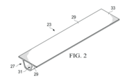
[00040] A FIG. 2 é uma ilustração de uma vista em perspectiva de uma longarina de resina compósita curada usando o sistema de bexiga não ven-tilada mostrado na FIG. 1.[00040] FIG. 2 is an illustration of a perspective view of a composite resin stringer cured using the non-ventilated bladder system shown in FIG. 1.
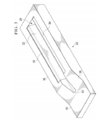
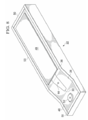
[00041] A FIG. 3 é uma ilustração de uma vista em perspectiva de uma ferramenta de cura usada na cura de uma carga de longarina compósita.[00041] FIG. 3 is an illustration of a perspective view of a curing tool used to cure a composite stringer load.
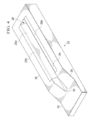
[00042] A FIG. 4 é uma ilustração similar à FIG. 3, porém, que mostra uma carga de longarina que foi colocada sobre a ferramenta.[00042] FIG. 4 is an illustration similar to FIG. 3, however, which shows a stringer load that was placed on the tool.
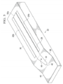
[00043] A FIG. 5 é uma ilustração similar à FIG. 4, porém, que mostra uma bexiga inflável que foi colocada dentro da cavidade da carga de longa-rina.[00043] FIG. 5 is an illustration similar to FIG. 4, however, showing an inflatable bladder that has been placed inside the long-ridge cargo cavity.
[00044] A FIG. 6 é uma ilustração similar à FIG. 5, porém, que mostra adicionalmente uma carga de revestimento que foi colocada sobre a carga de longarina.[00044] FIG. 6 is an illustration similar to FIG. 5, however, which additionally shows a coating load that has been placed on the stringer load.
[00045] A FIG. 7 é uma ilustração similar à FIG. 6, porém, que mostra uma placa de coifa que foi instalada ao longo da carga de revestimento.[00045] FIG. 7 is an illustration similar to FIG. 6, however, showing a hood plate that has been installed along the coating load.
[00046] A FIG. 8 é uma ilustração similar à FIG. 7, porém, que mostra a fita selante que foi aplicada ao redor da periferida da ferramenta de cura.[00046] FIG. 8 is an illustration similar to FIG. 7, however, which shows the sealing tape that was applied around the periphery of the curing tool.
[00047] A FIG. 9 é uma ilustração de uma vista em perspectiva de uma extremidade da ferramenta de cura mostrada na FIG. 8, um reservatório de fluido flexível que foi instalado na ferramenta de cura e acoplado à bexiga flexível.[00047] FIG. 9 is an illustration of a perspective view of an end of the curing tool shown in FIG. 8, a flexible fluid reservoir that was installed in the curing tool and attached to the flexible bladder.
[00048] A FIG. 10 é uma ilustração de uma vista transversal tomada ao longo da linha 10-10 na FIG. 9, porém, que mostra adicionalmente um saco de vácuo que foi instalado e vedado à ferramenta de cura.[00048] FIG. 10 is an illustration of a cross-sectional view taken along line 10-10 in FIG. 9, however, which additionally shows a vacuum bag that has been installed and sealed to the curing tool.
[00049] A FIG. 11 é uma ilustração de uma vista transversal similar à FIG. 10, porém, que mostra uma modalidade alternativa que emprega uma divisória dentro da bexiga, sendo que a bexiga é mostrada em seu estado não pressurizado.[00049] FIG. 11 is an illustration of a cross-sectional view similar to FIG. 10, however, which shows an alternative modality that employs a partition inside the bladder, with the bladder being shown in its non-pressurized state.
[00050] A FIG. 12 é uma ilustração similar à FIG. 11, porém, que mostra a bexiga que foi pressurizada através da pressão da autoclave aplicada ao reservatório de fluido através do saco de vácuo.[00050] FIG. 12 is an illustration similar to FIG. 11, however, showing the bladder that was pressurized through the pressure of the autoclave applied to the fluid reservoir through the vacuum bag.
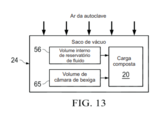
[00051] A FIG. 13 é uma ilustração de uma vista diagramática que mos-tra os volumes de fluido que atingem a carga compósita no caso de um va-zamento no sistema de bexiga não ventilada.[00051] FIG. 13 is an illustration of a diagrammatic view showing the fluid volumes that reach the composite load in the event of a leak in the non-ventilated bladder system.
[00052] A FIG. 14 é uma ilustração de um fluxograma de um método de cura em autoclave de uma carga de peça compósita que tem uma cavidade interna que usa um sistema de bexiga não ventilada.[00052] FIG. 14 is an illustration of a flow chart of an autoclave curing method for a composite part load that has an internal cavity that uses an unventilated bladder system.
[00053] A FIG. 15 é uma ilustração de um fluxograma de um método al-ternativo de cura em autoclave de uma carga de peça compósita que usa um sistema de bexiga não ventilada.[00053] FIG. 15 is an illustration of a flowchart of an alternative method of autoclave curing of a composite part load using an unventilated bladder system.
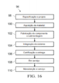
[00054] A FIG. 16 é uma ilustração de um fluxograma de metodologia de produção e serviço de aeronave.[00054] FIG. 16 is an illustration of a flowchart of aircraft production and service methodology.
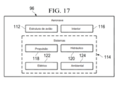
[00055] A FIG. 17 é uma ilustração de um diagrama de blocos de uma aeronave.[00055] FIG. 17 is an illustration of an aircraft block diagram.
[00056] Referindo-se primeiro à FIG. 1, uma peça de resina compósita não curada 20, posteriormente referida como uma "carga", uma "carga com-pósita", uma "carga de peça compósita" ou uma "carga de longarina", é cu-rada em uma ferramenta de cura 22 situada em uma autoclave 26 em que calor e pressão de autoclave são aplicados à carga compósita 20. A carga compósita 20 inclui um ou mais espaços vazios internos, áreas aprisiona-das ou delimitadas, ou cavidades, que para facilidade de descrição, serão coletivamente referidas posteriormente no presente documento como uma cavidade 28. Uma bexiga inflável flexível 30 se situa dentro da cavidade 28 antes de um ciclo de cura, a fim de reagir as pressões da autoclave aplica-das à carga 20 durante a cura. Um reservatório de fluido flexível 32 é mon-tado na ferramenta de cura 22 e é acoplado à bexiga 30 de uma maneira que forme um sistema fechado de bexiga 25 que não seja ventilado até a atmosfera dentro da autoclave 26. Em outras palavras, a bexiga 30 e o re-servatório de fluido 32 formam um sistema de fluido fechado que não é dire-tamente exposto à atmosfera interna da autoclave 26. Um saco flexível, tal como, um saco de vácuo 24, é colocado ao longo e vedado à ferramenta de cura 22, que cobre a carga compósita 20, a bexiga 30 e o reservatório de fluido 32. O saco flexível 24 é adaptado para ser acoplado a uma fonte de vácuo adequada 64 para evacuar o saco flexível 24. Durante a cura, a bexiga 30 é pressurizada usando um fluido substancialmente não compressível (não mostrado) fornecido a partir do reservatório de fluido 32.[00056] Referring first to FIG. 1, an uncured
[00057] Conforme será discutido em mais detalhes abaixo, devido ao fa-to de tanto a bexiga 30 como o reservatório de fluido 32 se situarem embaixo do saco de vácuo 24, a bexiga 30 não é ventilada até a atmosfera interna da autoclave 26, isto é, a bexiga 30 é não ventilada. De preferência, a combi-nação da bexiga 30 e do reservatório de fluido 32 forma um sistema de be-xiga não ventilada fechado 25 que é controlado pela pressão de ar da auto-clave exercida no saco de vácuo 24. De maneira opcional, a bexiga 30 pode incluir uma divisória interna 35 que separa substancialmente o volume interno total da bexiga 30 do fluido fornecido a partir do reservatório de fluido 32. A redução da pressão dentro do reservatório de fluido 32 permite que a bexiga 30 sofra um colapso ligeiramente parcial impedindo, deste modo, que a bexiga 30 se torne "travada" na carga compósita 20 e facilite a remo-ção fácil da bexiga 30 da carga compósita curada 20.[00057] As will be discussed in more detail below, due to the fact that both the
[00058] Referindo-se agora à FIG. 2, o sistema de bexiga não ventilada e o método de cura descritos podem ser empregados para curar qualquer uma entre uma variedade de peças de resina compósita de diversas geome-trias, que tem uma ou mais cavidades internas. Por exemplo, e sem limita-ção, o sistema e método descritos podem ser usados na fabricação de uma longarina de resina compósita reforçada com fibra 23, que pode compreen-der uma bandeja multicamadas de pré-impregnado. A longarina 23 inclui um perfilado reforçador 27 que forma uma cavidade interna 31, um par de seções de flange que se estende lateralmente 29 e uma seção de revesti-mento substancialmente plana 33 que é consolidada junto com as seções de flange 29 durante a cura. Outras geometrias de longarina são possíveis.[00058] Referring now to FIG. 2, the unventilated bladder system and the curing method described can be employed to cure any of a variety of composite resin pieces of various geometries, which have one or more internal cavities. For example, and without limitation, the described system and method can be used in the manufacture of a fiber-reinforced
[00059] As FIGS. 3 a 10 ilustram respectivamente os sucessivos está-gios na preparação do aparelho mostrado na FIG. 1 para cura da longarina 23 mostrada na FIG. 2. Referindo-se particularmente à FIG. 3, uma ferra-menta de cura 22 produzida a partir de qualquer material adequado inclui uma cavidade interna 28 que define uma face de ferramenta de perfilado reforçador 32, e um par de faces de ferramenta de seção de flange que se estende lateralmente 34. As faces de ferramenta 32, 34 são configuradas para combinar respectivamente a geometria do perfilado reforçador e seções de flange 27, 29, respectivamente, da longarina 23. A ferramenta de cura 22 tem uma superfície de ferramenta superior substancialmente plana 36 que circunda a cavidade interna 28, uma superfície chanfrada 38 em uma ex-tremidade da cavidade 28, e uma seção de extremidade substancialmente plana 40. Uma extremidade da cavidade interna 28 é aberta em 42. Confor-me será discutido abaixo, a ferramenta de cura 22 pode ser usada para montar as cargas de longarina compósita, e curar as cargas montadas den-tro de uma autoclave 26 (FIG. 1). Embora a ferramenta de cura ilustrada 22 tenha uma geometria que seja adaptada para combinar os recursos da lon-garina 23, deve-se notar que o sistema de bexiga não ventilada descrito 25 pode ser usado com as ferramentas de cura que têm qualquer uma de di-versas outras geometrias, dependendo da aplicação e da carga de peça compósita particular a ser curada.[00059] FIGS. 3 to 10 respectively illustrate the successive stages in the preparation of the apparatus shown in FIG. 1 for curing
[00060] Referindo-se à FIG. 4, uma carga de longarina compósita 20 é colocada na ferramenta de cura 22. A carga de longarina 20 compreende uma cobertura 20a que preenche a cavidade 28 e engata a face de ferra-menta 32 (FIG. 3), e um par de flanges que se estendem lateralmente 20b, que engatam respectivamente as faces de ferramenta 34. A carga de longa-rina 20 pode ser depositada em uma ferramenta de bandeja separada (não mostrada) e, então, transferida para a ferramenta de cura 22, ou de maneira alternativa, dependendo da geometria da carga de peça, é possível deposi-tar a longarina diretamente na ferramenta de cura 22.[00060] Referring to FIG. 4, a
[00061] Referindo-se agora à FIG. 5, após a carga de longarina 20 ter si-do colocada na ferramenta de cura 22, uma bexiga flexível 30 é colocada dentro da cavidade 28 (FIG. 4) da carga de longarina 20 a fim de reagir as pressões da autoclave que são aplicadas durante um ciclo de cura. A bexi-ga 30 pode ser formada de qualquer material adequado tal como, por exem-plo, e sem limitação, um elastômero. Um agente de liberação pode ser apli-cado à bexiga 30 antes de ser instalada para facilitar a remoção posterior da bexiga da cavidade 28 seguindo a cura. A bexiga 30 inclui um orifício de ventilação de bexiga 44 que é adaptado para ser acoplado ao reservatório de fluido 32 mostrado na FIG. 1, conforme será discutido abaixo. Neste exemplo, a bexiga 30 é configurada para combinar substancialmente a ge-ometria da cavidade 28 e tem uma superfície superior substancialmente plana 30a que é substancialmente alinhada às superfícies de ferramenta planas 36 da ferramenta de cura 22.[00061] Referring now to FIG. 5, after the
[00062] Referindo-se agora à FIG. 6, após a bexiga 30 ter sido instalada, conforme mostrado na FIG. 5, uma carga de revestimento compósita subs-tancialmente plana 46 é colocada na ferramenta de cura 22, sobrepondo a bexiga 30 e em contato face a face com os flanges 20b (FIG. 5) da carga de longarina 20 e das superfícies de ferramenta planas 36. A seguir, conforme mostrado na FIG. 7, uma placa de coifa 48 pode ser instalada ao longo da carga de revestimento compósita plana 46, a fim de aplicar a pressão substancialmente uniforme ao longo da carga de revestimento 46 durante um processo de cura. Também, embora não mostrado na FIG. 7, peel plies, fil-mes de liberação e/ou respiradores ou outros componentes podem ser insta-lados junto com a placa de coifa 48, dependendo da aplicação. Conforme mostrado na FIG. 8, uma fita selante adequada 50 ou outro vedante ade-quado é aplicado ao perímetro da ferramenta de cura 22 em preparação para o ensacamento a vácuo da ferramenta 22. Neste ponto, uma base de sonda de vácuo 52 pode ser aplicada à seção de extremidade plana 40 da ferra-menta de cura 22.[00062] Referring now to FIG. 6, after the
[00063] A seguir, conforme mostrado na FIG. 9, um reservatório de fluido flexível 32 é conectado à bexiga 30, de modo que a bexiga 30 e o reservató-rio de fluido 32 possam ser instalados e removidos como uma única monta-gem, se desejado. O reservatório de fluido 32 é acoplado ao orifício de venti-lação 44 (FIG. 8) na bexiga 30 e é suportado na superfície chanfrada 38 da ferramenta de cura 22 quando a bexiga 30 estiver no lugar dentro da cavi-dade de carga compósita 28. O reservatório de fluido 32 pode ser permanen-temente conectado e vedado à bexiga 30 livrando-se, deste modo, da necessidade de reconectar a bexiga 30 a uma fonte de pressão toda vez que a bexiga 30 for instalada em uma carga compósita 20 em preparação para um processo de cura. Esta disposição também elimina a necessidade de colo-car um selante ao redor do orifício de ventilação 44 toda vez que a bexiga for instalada em uma carga compósita 20. O reservatório de fluido 32 pode ser fabricado a partir de qualquer material adequado, tal como, sem limita-ção, um elastômero. Uma sonda de vácuo 54 é montada na base de sonda de vácuo 52, e é adaptada para ser acoplada a uma fonte de vácuo (não mostrada) para evacuar o saco de vácuo 24 durante um ciclo de cura.[00063] Next, as shown in FIG. 9, a
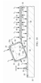
[00064] Referindo-se agora à FIG. 10, o reservatório de fluido 32 pode ter um formato em corte transversal geralmente retangular ou quadrado com lados 32a que são flexíveis e podem se deformar plasticamente para dentro, conforme mostrado pelas linhas tracejadas 32b quando a pressão externa for aplicada ao reservatório de fluido 32. Uma porção 32b do reservatório de fluido 32 é conectada em contato face a face a uma extremidade da bexiga 30 e inclui uma saída de fluido 41 que é alinhada e acoplada ao orifício de ventilação 44 na bexiga 30, permitindo que o fluido flua entre o reservatório de fluido 32 e a bexiga 30. Em outras modalidades, o reservatório de fluido 32 pode ter um formato diferente, e pode ser ou não conectado à bexiga 30. Seguindo a instalação do reservatório de fluido 32 mostrado na FIG. 9, o saco flexível 24, algumas vezes referido como um saco de vácuo 24, forma-do por qualquer material adequado, tal como, poliéster ou nylon, é instalado ao longo da ferramenta 22, cobrindo o reservatório de fluido 32, as cargas de longarina 20, 46 e a bexiga 30. O saco de vácuo 24 fica em contato face a face com o reservatório de fluido 32. O saco de vácuo 24 é vedado à peri-feria da ferramenta de cura 22 e ao redor da sonda de vácuo 54 usando a fita selante 50 ou outros selantes adequados. A evacuação do saco de vá-cuo 24 baixa o saco de vácuo 24 em contato face a face com os lados do reservatório de fluido 32, permitindo que a pressão da autoclave PA seja aplicada ao reservatório de fluido 32.[00064] Referring now to FIG. 10, the
[00065] De maneira opcional, o reservatório de fluido 32 pode incluir uma porta de vácuo 60 que é adaptada para ser acoplada a uma fonte de vácuo (não mostrada) após o saco de vácuo 24 ter sido removido seguindo um ciclo de cura. A porta de vácuo 60 é fechada e vedada embaixo do saco de vácuo 24 durante a cura, porém, inclui uma válvula ou outro dispositivo (não mostrado) que permite a conexão do volume interno 56 do reservatório de fluido 32 à fonte de vácuo após a cura ser concluída e o saco de vácuo ter sido removido. O acoplamento do reservatório de fluido 32 à fonte de vá-cuo, desta maneira, alivia a pressão de fluido dentro do reservatório de flui-do 32 que, por sua vez, reduz a pressão dentro da bexiga 30, permitindo que a bexiga 30 esvazie ou entre ligeiramente em colapso. O esvaziamento da bexiga 30, desta maneira, reduz a dimensão em corte transversal máxima (não mostrada) da bexiga 30 em uma quantidade que é suficiente para per-mitir que a bexiga 30 seja removida da longarina curada.[00065] Optionally, the
[00066] Durante uma cura realizada dentro de uma autoclave, a pressão da autoclave PA força o saco de vácuo 24 contra a ferramenta de cura 22 compactando, deste modo, a carga compósita 20 enquanto também aplica pressão ao reservatório de fluido 32. A pressão da autoclave PA aplicada ao reservatório de fluido 32 faz com que o fluido flua 45 a partir do volume in-terno 56 do reservatório de fluido 32 através do orifício de ventilação de be-xiga 44 para dentro da bexiga 30 pressurizando, deste modo, intemamente a bexiga 30. Esta pressurização da bexiga 30 faz com que uma força 55 seja aplicada à carga compósita 20 que reage a pressão da autoclave PA aplica-da à carga compósita 20. Quando a cura for concluída, a pressão da autoclave PA é removida do saco de vácuo 22 e, deste modo, é removida do re-servatório de fluido 32. A redução resultante na pressão de fluido dentro do reservatório de fluido 32 permite que o fluido flua a partir da bexiga 58 atra-vés do orifício de ventilação 44 de volta para o reservatório de fluido 32.[00066] During a cure performed inside an autoclave, the pressure of the PA autoclave forces the
[00067] Conforme previamente discutido, o reservatório de fluido 32 po-de ser permanentemente vedado à bexiga 30 se livrando, deste modo, da necessidade de colocar um selante ao redor do orifício de ventilação 44 (FIG. 8) toda vez que a bexiga 30 for instalada em uma carga compósita 20. A vedação permanente do reservatório de fluido 32 à bexiga 30, portanto, pode eliminar o vazamento ao redor do orifício de ventilação 44 para dentro da carga compósita 20. No caso de um vazamento na bexiga 30 ou no re-servatório de fluido 32, o vazamento de fluido para dentro da carga compósi-ta 20 é limitado ao volume total da bexiga 30 e do reservatório de fluido 32, uma vez que o sistema de bexiga 25 (FIG. 1) é um sistema fechado e não permite que o ar da autoclave entre na cavidade de carga compósita 28 (FIG. 4).[00067] As previously discussed, the
[00068] Uma modalidade alternativa do sistema de bexiga não ventilada descrito é mostrada nas FIGS. 11 e 12. Nesta modalidade, a bexiga 30 inclui uma divisória interna 35 que separa a câmara interior 65 da bexiga 30 do fluido fornecido pelo reservatório de fluido 32. A divisória 35 é produzida de um material flexível e pode ser formada integral à bexiga 30. A câmara de bexiga 65 é preenchida com um material de preenchimento fluxível 66 que tem um CTE (coeficiente de expansão térmica) relativamente baixo e uma densidade selecionada para dotar a bexiga 30 com um nível desejado de rigidez. Um lado 75 da divisória 35 é exposto ao fluido fornecido pelo reser-vatório de fluido 32. O fluido a partir do reservatório 56, que é forçado contra a bexiga 30 através da pressão da autoclave PA, exerce a pressão de fluido PF (FIG. 12) contra a divisória 35, fazendo com que a divisória 35 flexione para dentro até a posição 35a mostrada na FIG. 12 pressurizando, deste modo, o material de preenchimento 66. A pressurização do material de pre-enchimento 66 resulta em uma pressão para fora 68 que é exercida contra a carga compósita 20.[00068] An alternative embodiment of the described non-ventilated bladder system is shown in FIGS. 11 and 12. In this embodiment, the
[00069] Referindo-se agora à FIG. 13, no caso de um vazamento no sis-tema de bexiga não ventilada 25 descrito acima, o volume de ar dentro da autoclave 26 (FIG. 1) não atinge a carga compósita 20, porque o sistema de bexiga 25 é vedado embaixo do saco de vácuo 24. De preferência, a quanti-dade total de fluido que atinge possivelmente a carga compósita 20 no caso de um vazamento da bexiga 30 ou do reservatório de fluido 32 (FIGS. 10-12) é limitada ao volume interior do reservatório de fluido 56 mais o volume da câmara de bexiga 65.[00069] Referring now to FIG. 13, in the case of a leak in the
[00070] A atenção é voltada agora à FIG. 14 que ilustra amplamente as etapas de um método para cura em autoclave que usa o sistema de bexiga não ventilada 25 descrito acima. Começando na etapa 70, uma carga de resina compósita 20 é colocada em uma ferramenta adequada, que pode ser uma ferramenta de cura. Em 72, uma bexiga inflável flexível 30 é insta-lada em uma cavidade interna 28 da carga 20. Em 74, a bexiga flexível 30 é acoplada a um reservatório de fluido flexível 32 que contém uma quantida-de de fluido. Em 76, a carga compósita 20 junto com o reservatório de fluido 32 é coberta com um saco flexível 24, tal como, um saco de vácuo que, en-tão, é vedado à ferramenta de cura 22. Em 78, a pressão da autoclave PA é aplicada ao saco 24, a fim de comprimir o reservatório de fluido 32 e forçar o fluido a partir do reservatório 32 para dentro da bexiga 30 pressurizando, deste modo, a bexiga 30 para reagir as forças aplicadas à carga compósita 20 através da pressão da autoclave. De maneira opcional, na etapa 80, uma divisória interna 35 dentro da bexiga 30 pode ser empregada para transmitir a pressão para a bexiga 30 usando a pressão de fluido gerada pelo reserva-tório de fluido 32. Também, de maneira opcional, na etapa 82, seguindo a cura e a remoção do saco de vácuo 24, a pressão dentro do reservatório de fluido 32 pode ser aliviada para auxiliar na remoção da bexiga, acoplando-se o reservatório de fluido 32 a uma fonte de vácuo adequada.[00070] Attention is now turned to FIG. 14 which broadly illustrates the steps of an autoclave healing method using the
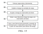
[00071] Um método alternativo de cura de uma carga de peça compósita 20 é mostrado na FIG. 15. Em 84, uma carga de peça compósita 20 é colo-cada em uma ferramenta 22, e em 86, uma bexiga 30 é instalada em uma cavidade 28 da carga de peça compósita 20. A bexiga 60 é acoplada a um reservatório de fluido 32 na etapa 88. A seguir, conforme mostrado na etapa 90, um saco flexível 24 é vedado ao longo da carga de peça compósita 20 e do reservatório de fluido 32. Na etapa 92, o saco flexível 24 é usado para transmitir a pressão da autoclave para o reservatório de fluido 32 para forçar o fluido a partir do reservatório 32 para dentro da bexiga 60.[00071] An alternative method of curing a
[00072] As modalidades da descrição podem encontrar uso em uma va-riedade de aplicações potenciais, particularmente, na indústria de transpor-te, que incluem, por exemplo, aplicações aeroespaciais, marítimas, automo-tivas e outras aplicações onde a cura em autoclave de peças compósitas possa ser usada. Deste modo, referindo-se agora às FIGS. 16 e 17, as mo-dalidades da descrição podem ser usadas no contexto de um método de fabricação e serviço de aeronave 94, conforme mostrado na FIG. 16 e uma aeronave 96, conforme mostrado na FIG. 16. As aplicações de aeronave das modalidades descritas podem incluir, por exemplo, sem limitação, a cura de elementos mais rígidos, tais como, sem limitação, vigas, longerões e longa-rinas, para citar apenas alguns. Durante a pré-produção, o método exempli-ficativo 94 pode incluir a especificação e o projeto 98 da aeronave 96 e a aquisição de material 100. Durante a produção, a fabricação de componente e submontagem 102 e a integração de sistema 104 da aeronave 96 ocorrem. Posteriormente, a aeronave 96 pode passar por certificação e entrega 96 a fim de ser colocada em serviço 108. Enquanto em serviço por um cliente, a aeronave 96 é programada para manutenção e serviço de rotina 110, que também podem incluir modificação, reconfiguração, restauração, e assim por diante.[00072] The description modalities can find use in a variety of potential applications, particularly in the transport industry, which include, for example, aerospace, marine, automotive and other applications where autoclave curing composite parts can be used. Thus, referring now to FIGS. 16 and 17, the modalities of the description can be used in the context of an aircraft manufacturing and
[00073] Cada um dos processos do método 94 pode ser executado ou realizado por um integrador de sistema, terceiros e/ou um operador (por exemplo, um cliente). Para os propósitos desta descrição, um integrador de sistema pode incluir sem limitação qualquer número de fabricantes de ae-ronave e subcontratantes de sistema principais; terceiros podem incluir, sem limitação, qualquer número de vendedores, subcontratantes e fornecedores; e um operador pode ser uma companhia aérea, empresa de leasing, entida-de militar, organização de serviços, e assim por diante.[00073] Each of the
[00074] Conforme mostrado na FIG. 17, a aeronave 96 produzida pelo método exemplificativo 94 pode incluir uma estrutura de avião 112 com uma pluralidade de sistemas 114 e um interior 116. Os exemplos de sistemas de alto nível 114 incluem um ou mais entre um sistema de propulsão 18, um sistema elétrico 120, um sistema hidráulico 122 e um sistema ambiental 124. Qualquer número de outros sistemas pode ser incluído. Embora um exem-plo aeroespacial seja mostrado, os princípios da descrição podem ser apli-cados a outras indústrias, tais como, as indústrias marítimas e automotivas.[00074] As shown in FIG. 17,
[00075] Os sistemas e os métodos incorporados no presente documento podem ser empregados durante qualquer um ou mais dos estágios do mé-todo de produção e serviço 94. Por exemplo, os componentes ou submonta-gens que correspondem ao processo de produção 102 podem ser fabrica-dos ou manufaturados de uma maneira similar aos componentes ou sub-montagens produzidos enquanto a aeronave 96 se encontra em serviço. Também, uma ou mais modalidades de aparelho, modalidades de método, ou uma combinação destas podem ser utilizadas durante os estágios de produção 102 e 104, por exemplo, promovendo-se substancialmente a mon-tagem ou a redução do custo de uma aeronave 96. De maneira similar, uma ou mais modalidades de aparelho, modalidades de método, ou uma combi-nação destas podem ser utilizadas enquanto a aeronave 96 se encontra em serviço, por exemplo, e sem limitação, em manutenção e serviço 110.[00075] The systems and methods incorporated in this document can be used during any one or more of the stages of the production and
[00076] A descrição das diferentes modalidades vantajosas foi apresen-tada para propósitos de ilustração e descrição, e não se destina a ser exaus-tiva ou limitada às modalidades na forma descrita. Muitas modificações e variações serão aparentes para aqueles versados na técnica. Ademais, dife-rentes modalidades vantajosas podem proporcionar diferentes vantagens quando comparadas a outras modalidades vantajosas. A modalidade ou as modalidades selecionadas são escolhidas e descritas a fim de explicar me-lhor os princípios das modalidades, a aplicação prática, e permitir que outros versados na técnica entendam a descrição para diversas modalidades com diversas modificações, à medida que são adequadas ao uso particular con-templado.[00076] The description of the different advantageous modalities has been presented for purposes of illustration and description, and is not intended to be exhaustive or limited to the modalities in the manner described. Many modifications and variations will be apparent to those skilled in the art. In addition, different advantageous modalities can provide different advantages when compared to other advantageous modalities. The selected modality or modalities are chosen and described in order to better explain the principles of the modalities, their practical application, and to allow others skilled in the art to understand the description for various modalities with various modifications, as they are suitable for use particularly contemplated.
Claims (14)
uma bexiga flexível (30) adaptada para ser colocada na cavidade para aplicar pressão sobre a carga compósita (20) durante a cura;
um reservatório de fluido (32) para pressurizar a bexiga (30), o reservatório (32) e a bexiga (30) sendo acoplados entre si em um sistema fechado (25); e
um saco flexível (24) vedado ao longo da bexiga flexível (30) e do reservatório de fluido (32) em que o saco flexível (24) está em contato frente a frente com o reservatório de fluido (32).Apparatus for use in autoclave curing (26) of a composite load (20) that has an internal cavity (28), characterized by the fact that it comprises:
a flexible bladder (30) adapted to be placed in the cavity to apply pressure on the composite load (20) during curing;
a fluid reservoir (32) for pressurizing the bladder (30), the reservoir (32) and the bladder (30) being coupled together in a closed system (25); and
a flexible bag (24) sealed along the flexible bladder (30) and the fluid reservoir (32) in which the flexible bag (24) is in contact face to face with the fluid reservoir (32).
uma ferramenta de cura (22) adaptada para ter a carga compósita (20) situada nesta, e
em que o reservatório de fluido (32) se situa na ferramenta (22) de cura (22) e o saco flexível (24) é vedado à ferramenta (22) curada.Apparatus according to claim 1 or 2, characterized by the fact that it further comprises:
a curing tool (22) adapted to have the composite load (20) located there, and
wherein the fluid reservoir (32) is located on the curing tool (22) and the flexible bag (24) is sealed to the cured tool (22).
a bexiga (30) inclui um orifício de ventilação (44), e
uma porção (32) do reservatório de fluido (32) é conectada à bexiga (30) e inclui uma saída de fluido (41) acoplada ao orifício de ventilação na bexiga (30).Apparatus according to any one of claims 1 to 4, characterized by the fact that:
the bladder (30) includes a ventilation hole (44), and
a portion (32) of the fluid reservoir (32) is connected to the bladder (30) and includes a fluid outlet (41) coupled to the ventilation hole in the bladder (30).
uma divisória (35) que forma uma câmara interior (65) dentro da bexiga (30), e
um material de preenchimento (66) que preenche a câmara interior (65) e que tem uma densidade que é suficiente para endurecer a bexiga (30) quando a bexiga (30) for pressurizada pelo fluido a partir do reservatório de fluido (32).Apparatus according to any of the preceding claims, characterized by the fact that the bladder (30) includes:
a partition (35) that forms an inner chamber (65) within the bladder (30), and
a filling material (66) that fills the inner chamber (65) and that has a density that is sufficient to harden the bladder (30) when the bladder (30) is pressurized by the fluid from the fluid reservoir (32).
a divisória (35) inclui um lado flexível que é exposto ao fluido a partir do fluido do reservatório de fluido (32), e
o lado flexível flexiona para aplicar a pressão ao material de preenchimento (66) quando o reservatório de fluido (32) pressurizar a bexiga (30).Apparatus, according to claim 7, characterized by the fact that:
the partition (35) includes a flexible side that is exposed to the fluid from the fluid in the fluid reservoir (32), and
the flexible side flexes to apply pressure to the filling material (66) when the fluid reservoir (32) pressurizes the bladder (30).
colocar (70) a carga compósita (20) em uma ferramenta (22);
instalar (72) uma bexiga (30) dentro da cavidade;
acoplar (74) a bexiga (30) a um reservatório de fluido (32);
vedar (76) um saco flexível (24) ao longo da carga compósita (20) e do reservatório (32) em contato frente a frente com o reservatório de fluido (32); e
usar (78) o saco flexível (24) para transmitir a pressão da autoclave (26) para o reservatório (32) para forçar o fluido a partir do reservatório (32) para dentro da bexiga (30).Autoclave curing method (26) of a composite load (20) that has an internal cavity (28), characterized by the fact that it comprises:
placing (70) the composite load (20) on a tool (22);
installing (72) a bladder (30) into the cavity;
coupling (74) the bladder (30) to a fluid reservoir (32);
seal (76) a flexible bag (24) along the composite load (20) and the reservoir (32) in contact face to face with the fluid reservoir (32); and
use (78) the flexible bag (24) to transmit the pressure from the autoclave (26) to the reservoir (32) to force the fluid from the reservoir (32) into the bladder (30).
endurecer a bexiga (30) preenchendo-se a bexiga (30) com um material de preenchimento (66), e
separar o material de preenchimento (66) do fluido colocando-se (80) uma divisória (35) na bexiga (30).Method according to any one of claims 9 to 11, characterized by the fact that it further comprises:
harden the bladder (30) by filling the bladder (30) with a filling material (66), and
separate the filling material (66) from the fluid by placing (80) a divider (35) in the bladder (30).
usar um vácuo para extrair o saco flexível (24) para baixo contra os lados do reservatório (32).Method according to any one of claims 9 to 12, characterized by the fact that it further comprises:
use a vacuum to extract the flexible bag (24) down against the sides of the reservoir (32).
remover o saco flexível (24) da carga compósita (20) e do reservatório (32) após a carga compósita (20) ter sido curada; e
aliviar a pressão dentro da bexiga (30) carregando-se o reservatório (32) até uma fonte de vácuo (64) após o saco flexível (24) ter sido removido (82).Method according to any one of claims 9 to 13, characterized by the fact that it further comprises:
removing the flexible bag (24) from the composite load (20) and the reservoir (32) after the composite load (20) has been cured; and
relieve pressure inside the bladder (30) by loading the reservoir (32) to a vacuum source (64) after the flexible bag (24) has been removed (82).
Applications Claiming Priority (2)
| Application Number | Priority Date | Filing Date | Title |
|---|---|---|---|
| US13/491,698 | 2012-06-08 | ||
| US13/491,698 US9381704B2 (en) | 2012-06-08 | 2012-06-08 | Non-vented bladder system for curing composite parts |
Publications (2)
| Publication Number | Publication Date |
|---|---|
| BR102013014257A2 BR102013014257A2 (en) | 2015-06-23 |
| BR102013014257B1 true BR102013014257B1 (en) | 2020-12-01 |
Family
ID=48468178
Family Applications (1)
| Application Number | Title | Priority Date | Filing Date |
|---|---|---|---|
| BR102013014257-3A BR102013014257B1 (en) | 2012-06-08 | 2013-06-07 | apparatus and method for use in autoclave curing of a composite load |
Country Status (9)
| Country | Link |
|---|---|
| US (2) | US9381704B2 (en) |
| EP (1) | EP2671709B1 (en) |
| JP (1) | JP6170346B2 (en) |
| KR (1) | KR102052923B1 (en) |
| CN (1) | CN103481433B (en) |
| BR (1) | BR102013014257B1 (en) |
| CA (1) | CA2812376C (en) |
| ES (1) | ES2564140T3 (en) |
| RU (1) | RU2660136C9 (en) |
Families Citing this family (16)
| Publication number | Priority date | Publication date | Assignee | Title |
|---|---|---|---|---|
| US9381704B2 (en) | 2012-06-08 | 2016-07-05 | The Boeing Company | Non-vented bladder system for curing composite parts |
| US9399509B2 (en) * | 2014-04-10 | 2016-07-26 | The Boeing Company | Vent stringer fitting |
| US9914244B2 (en) * | 2014-08-04 | 2018-03-13 | The Boeing Company | Bladder system for curing composite parts |
| US9399510B2 (en) * | 2014-08-20 | 2016-07-26 | The Boeing Company | Hat stringer closeout fitting and method of making same |
| US10144185B2 (en) * | 2015-04-01 | 2018-12-04 | The Boeing Company | Method and apparatus for high-temperature post-curing of UV-cured photopolymers |
| US10315366B2 (en) | 2015-05-11 | 2019-06-11 | Gulfstream Aerospace Corporation | Apparatuses and methods for making reinforcement structures |
| US10843416B2 (en) | 2015-05-11 | 2020-11-24 | Gulfstream Aerospace Corporation | Composite reinforcement structures and aircraft assemblies comprising composite reinforcement structures |
| US20160339682A1 (en) | 2015-05-18 | 2016-11-24 | The Boeing Company | Bladder System for Curing Composite Parts |
| US10293552B2 (en) | 2015-11-17 | 2019-05-21 | The Boeing Company | Heat shrinkable film tube and method for manufacturing hollow composite parts |
| US10639855B2 (en) * | 2017-02-07 | 2020-05-05 | General Electric Company | Applicator systems for applying pressure to a structure |
| US10751955B2 (en) | 2017-04-10 | 2020-08-25 | The Boeing Company | Unitized composite structure manufacturing system |
| US10710319B2 (en) * | 2017-08-02 | 2020-07-14 | The Boeing Company | Controlling application of forces to different portions of object surface using bladder |
| US10710320B2 (en) * | 2017-08-02 | 2020-07-14 | The Boeing Company | Controlling application of forces to different portions of object surface using flexible wall |
| EP3587063B1 (en) | 2017-09-07 | 2022-03-09 | Kawasaki Jukogyo Kabushiki Kaisha | Mold for manufacturing composite material molded products, and method for manufacturing composite material molded products |
| CN108162433B (en) * | 2018-03-01 | 2020-04-10 | 江苏金风科技有限公司 | Vacuum infusion auxiliary device and vacuum infusion process |
| GB2575102A (en) * | 2018-06-29 | 2020-01-01 | Airbus Operations Ltd | Duct stringer with bulkhead |
Family Cites Families (19)
| Publication number | Priority date | Publication date | Assignee | Title |
|---|---|---|---|---|
| US4178406A (en) * | 1977-12-29 | 1979-12-11 | Rohm And Haas Company | Three-layered fiberglass construction |
| US4222721A (en) * | 1978-09-08 | 1980-09-16 | The Firestone Tire & Rubber Company | Apparatus for curing tires and the like |
| US5484277A (en) | 1989-12-26 | 1996-01-16 | Mcdonnell Douglas Corporation | Mandreless molding system |
| SU1785910A1 (en) * | 1990-02-19 | 1993-01-07 | B Yuzhn K | Method and device for producing composite laminated structures |
| US5366684A (en) * | 1992-12-31 | 1994-11-22 | Grumman Aerospace Corporation | Molding composite method using an inflatable bladder pressurized in an autoclave |
| CN100396472C (en) * | 2001-01-25 | 2008-06-25 | 快速科技有限公司 | Composite and metal component production, forming and bonding system |
| CA2484174C (en) * | 2002-05-29 | 2008-12-02 | The Boeing Company | Controlled atmospheric pressure resin infusion process |
| US7335012B2 (en) * | 2004-12-22 | 2008-02-26 | General Electric Company | Apparatus for fabricating reinforced composite materials |
| US8834782B2 (en) * | 2007-08-07 | 2014-09-16 | William L. Rodman | Composite structures and methods of making same |
| US9238335B2 (en) | 2008-07-10 | 2016-01-19 | The Boeing Company | Mandrel for autoclave curing applications |
| US9327467B2 (en) | 2008-07-10 | 2016-05-03 | The Boeing Company | Composite mandrel for autoclave curing applications |
| US8652371B2 (en) * | 2008-11-20 | 2014-02-18 | Cytec Technology Corp. | Constant pressure infusion process for resin transfer molding |
| JP5313646B2 (en) * | 2008-12-04 | 2013-10-09 | 株式会社ニューケミカル | Manufacturing method of fiber reinforced resin molded product |
| US8293051B2 (en) | 2008-12-10 | 2012-10-23 | The Boeing Company | Method for producing composite laminates using a collapsible mandrel |
| US20100186899A1 (en) * | 2009-01-15 | 2010-07-29 | Airtech International, Inc. | Thermoplastic mandrels for composite fabrication |
| US8074694B2 (en) | 2009-05-28 | 2011-12-13 | The Boeing Company | Stringer transition method |
| JP5430424B2 (en) * | 2010-01-28 | 2014-02-26 | 本田技研工業株式会社 | Method for forming aircraft wing structure |
| US8430984B2 (en) * | 2010-05-11 | 2013-04-30 | The Boeing Company | Collapsible mandrel employing reinforced fluoroelastomeric bladder |
| US9381704B2 (en) | 2012-06-08 | 2016-07-05 | The Boeing Company | Non-vented bladder system for curing composite parts |
-
2012
- 2012-06-08 US US13/491,698 patent/US9381704B2/en active Active
-
2013
- 2013-04-09 CA CA2812376A patent/CA2812376C/en active Active
- 2013-04-18 KR KR1020130042634A patent/KR102052923B1/en active IP Right Grant
- 2013-05-23 ES ES13169023.2T patent/ES2564140T3/en active Active
- 2013-05-23 EP EP13169023.2A patent/EP2671709B1/en active Active
- 2013-06-04 RU RU2013125720A patent/RU2660136C9/en active
- 2013-06-05 JP JP2013119019A patent/JP6170346B2/en active Active
- 2013-06-07 BR BR102013014257-3A patent/BR102013014257B1/en active IP Right Grant
- 2013-06-07 CN CN201310224985.1A patent/CN103481433B/en active Active
-
2016
- 2016-07-01 US US15/200,330 patent/US10040256B2/en active Active
Also Published As
| Publication number | Publication date |
|---|---|
| US10040256B2 (en) | 2018-08-07 |
| ES2564140T3 (en) | 2016-03-18 |
| RU2660136C2 (en) | 2018-07-05 |
| CN103481433B (en) | 2017-03-01 |
| US9381704B2 (en) | 2016-07-05 |
| CN103481433A (en) | 2014-01-01 |
| RU2660136C9 (en) | 2018-11-29 |
| CA2812376C (en) | 2015-06-23 |
| JP2014012399A (en) | 2014-01-23 |
| US20160311179A1 (en) | 2016-10-27 |
| BR102013014257A2 (en) | 2015-06-23 |
| US20130327477A1 (en) | 2013-12-12 |
| CA2812376A1 (en) | 2013-12-08 |
| KR20130138099A (en) | 2013-12-18 |
| EP2671709B1 (en) | 2016-02-03 |
| KR102052923B1 (en) | 2019-12-11 |
| JP6170346B2 (en) | 2017-07-26 |
| RU2013125720A (en) | 2014-12-10 |
| EP2671709A1 (en) | 2013-12-11 |
Similar Documents
| Publication | Publication Date | Title |
|---|---|---|
| BR102013014257B1 (en) | apparatus and method for use in autoclave curing of a composite load | |
| RU2687438C1 (en) | Method for determining composite articles using vacuum transfer | |
| KR102207476B1 (en) | Sealing and testing segmented tools | |
| BR112015004435B1 (en) | autoclave apparatus for curing composite stiffeners against a composite film, and method for curing composite stiffeners and a film within an autoclave | |
| US9925697B2 (en) | Method for bladder repair during composite part curing | |
| EP3365159B1 (en) | Method and apparatus for forming a composite skin-stiffener assembly | |
| BR112015006389B1 (en) | COMPOSITE TOOL HAVING VACUUM INTEGRITY, AND COMPOSITE TOOL FOR USE IN COMPOSITE PROCESSING PARTS WITH VACUUM BAG | |
| JP6594674B2 (en) | Air bag system for curing composite parts | |
| US11897210B2 (en) | Caul plate system for aircraft fabrication | |
| NL2027386B1 (en) | Caul plate system for aircraft fabrication | |
| EP4011606A2 (en) | Caul plate system for aircraft fabrication |
Legal Events
| Date | Code | Title | Description |
|---|---|---|---|
| B03A | Publication of a patent application or of a certificate of addition of invention [chapter 3.1 patent gazette] | ||
| B06F | Objections, documents and/or translations needed after an examination request according [chapter 6.6 patent gazette] | ||
| B06F | Objections, documents and/or translations needed after an examination request according [chapter 6.6 patent gazette] | ||
| B06I | Publication of requirement cancelled [chapter 6.9 patent gazette] |
Free format text: ANULADA A PUBLICACAO CODIGO 6.6.1 NA RPI NO 2462 DE 13/03/2018 POR TER SIDO INDEVIDA. |
|
| B06U | Preliminary requirement: requests with searches performed by other patent offices: procedure suspended [chapter 6.21 patent gazette] | ||
| B09A | Decision: intention to grant [chapter 9.1 patent gazette] | ||
| B16A | Patent or certificate of addition of invention granted [chapter 16.1 patent gazette] |
Free format text: PRAZO DE VALIDADE: 20 (VINTE) ANOS CONTADOS A PARTIR DE 07/06/2013, OBSERVADAS AS CONDICOES LEGAIS. |