JP6594674B2 - Air bag system for curing composite parts - Google Patents
Air bag system for curing composite parts Download PDFInfo
- Publication number
- JP6594674B2 JP6594674B2 JP2015125396A JP2015125396A JP6594674B2 JP 6594674 B2 JP6594674 B2 JP 6594674B2 JP 2015125396 A JP2015125396 A JP 2015125396A JP 2015125396 A JP2015125396 A JP 2015125396A JP 6594674 B2 JP6594674 B2 JP 6594674B2
- Authority
- JP
- Japan
- Prior art keywords
- bolt
- end fitting
- bladder
- tool
- pressure
- Prior art date
- Legal status (The legal status is an assumption and is not a legal conclusion. Google has not performed a legal analysis and makes no representation as to the accuracy of the status listed.)
- Active
Links
Images


Classifications
-
- B—PERFORMING OPERATIONS; TRANSPORTING
- B29—WORKING OF PLASTICS; WORKING OF SUBSTANCES IN A PLASTIC STATE IN GENERAL
- B29C—SHAPING OR JOINING OF PLASTICS; SHAPING OF MATERIAL IN A PLASTIC STATE, NOT OTHERWISE PROVIDED FOR; AFTER-TREATMENT OF THE SHAPED PRODUCTS, e.g. REPAIRING
- B29C70/00—Shaping composites, i.e. plastics material comprising reinforcements, fillers or preformed parts, e.g. inserts
- B29C70/04—Shaping composites, i.e. plastics material comprising reinforcements, fillers or preformed parts, e.g. inserts comprising reinforcements only, e.g. self-reinforcing plastics
- B29C70/28—Shaping operations therefor
- B29C70/40—Shaping or impregnating by compression not applied
- B29C70/42—Shaping or impregnating by compression not applied for producing articles of definite length, i.e. discrete articles
- B29C70/44—Shaping or impregnating by compression not applied for producing articles of definite length, i.e. discrete articles using isostatic pressure, e.g. pressure difference-moulding, vacuum bag-moulding, autoclave-moulding or expanding rubber-moulding
-
- B—PERFORMING OPERATIONS; TRANSPORTING
- B29—WORKING OF PLASTICS; WORKING OF SUBSTANCES IN A PLASTIC STATE IN GENERAL
- B29C—SHAPING OR JOINING OF PLASTICS; SHAPING OF MATERIAL IN A PLASTIC STATE, NOT OTHERWISE PROVIDED FOR; AFTER-TREATMENT OF THE SHAPED PRODUCTS, e.g. REPAIRING
- B29C33/00—Moulds or cores; Details thereof or accessories therefor
- B29C33/44—Moulds or cores; Details thereof or accessories therefor with means for, or specially constructed to facilitate, the removal of articles, e.g. of undercut articles
- B29C33/48—Moulds or cores; Details thereof or accessories therefor with means for, or specially constructed to facilitate, the removal of articles, e.g. of undercut articles with means for collapsing or disassembling
- B29C33/50—Moulds or cores; Details thereof or accessories therefor with means for, or specially constructed to facilitate, the removal of articles, e.g. of undercut articles with means for collapsing or disassembling elastic or flexible
- B29C33/505—Moulds or cores; Details thereof or accessories therefor with means for, or specially constructed to facilitate, the removal of articles, e.g. of undercut articles with means for collapsing or disassembling elastic or flexible cores or mandrels, e.g. inflatable
-
- B—PERFORMING OPERATIONS; TRANSPORTING
- B29—WORKING OF PLASTICS; WORKING OF SUBSTANCES IN A PLASTIC STATE IN GENERAL
- B29C—SHAPING OR JOINING OF PLASTICS; SHAPING OF MATERIAL IN A PLASTIC STATE, NOT OTHERWISE PROVIDED FOR; AFTER-TREATMENT OF THE SHAPED PRODUCTS, e.g. REPAIRING
- B29C43/00—Compression moulding, i.e. applying external pressure to flow the moulding material; Apparatus therefor
- B29C43/003—Compression moulding, i.e. applying external pressure to flow the moulding material; Apparatus therefor characterised by the choice of material
-
- B—PERFORMING OPERATIONS; TRANSPORTING
- B29—WORKING OF PLASTICS; WORKING OF SUBSTANCES IN A PLASTIC STATE IN GENERAL
- B29C—SHAPING OR JOINING OF PLASTICS; SHAPING OF MATERIAL IN A PLASTIC STATE, NOT OTHERWISE PROVIDED FOR; AFTER-TREATMENT OF THE SHAPED PRODUCTS, e.g. REPAIRING
- B29C70/00—Shaping composites, i.e. plastics material comprising reinforcements, fillers or preformed parts, e.g. inserts
- B29C70/04—Shaping composites, i.e. plastics material comprising reinforcements, fillers or preformed parts, e.g. inserts comprising reinforcements only, e.g. self-reinforcing plastics
- B29C70/28—Shaping operations therefor
- B29C70/40—Shaping or impregnating by compression not applied
- B29C70/42—Shaping or impregnating by compression not applied for producing articles of definite length, i.e. discrete articles
- B29C70/44—Shaping or impregnating by compression not applied for producing articles of definite length, i.e. discrete articles using isostatic pressure, e.g. pressure difference-moulding, vacuum bag-moulding, autoclave-moulding or expanding rubber-moulding
- B29C70/446—Moulding structures having an axis of symmetry or at least one channel, e.g. tubular structures, frames
-
- B—PERFORMING OPERATIONS; TRANSPORTING
- B29—WORKING OF PLASTICS; WORKING OF SUBSTANCES IN A PLASTIC STATE IN GENERAL
- B29C—SHAPING OR JOINING OF PLASTICS; SHAPING OF MATERIAL IN A PLASTIC STATE, NOT OTHERWISE PROVIDED FOR; AFTER-TREATMENT OF THE SHAPED PRODUCTS, e.g. REPAIRING
- B29C70/00—Shaping composites, i.e. plastics material comprising reinforcements, fillers or preformed parts, e.g. inserts
- B29C70/04—Shaping composites, i.e. plastics material comprising reinforcements, fillers or preformed parts, e.g. inserts comprising reinforcements only, e.g. self-reinforcing plastics
- B29C70/28—Shaping operations therefor
- B29C70/54—Component parts, details or accessories; Auxiliary operations, e.g. feeding or storage of prepregs or SMC after impregnation or during ageing
-
- B—PERFORMING OPERATIONS; TRANSPORTING
- B29—WORKING OF PLASTICS; WORKING OF SUBSTANCES IN A PLASTIC STATE IN GENERAL
- B29C—SHAPING OR JOINING OF PLASTICS; SHAPING OF MATERIAL IN A PLASTIC STATE, NOT OTHERWISE PROVIDED FOR; AFTER-TREATMENT OF THE SHAPED PRODUCTS, e.g. REPAIRING
- B29C43/00—Compression moulding, i.e. applying external pressure to flow the moulding material; Apparatus therefor
- B29C43/32—Component parts, details or accessories; Auxiliary operations
- B29C43/36—Moulds for making articles of definite length, i.e. discrete articles
- B29C43/3642—Bags, bleeder sheets or cauls for isostatic pressing
-
- B—PERFORMING OPERATIONS; TRANSPORTING
- B29—WORKING OF PLASTICS; WORKING OF SUBSTANCES IN A PLASTIC STATE IN GENERAL
- B29L—INDEXING SCHEME ASSOCIATED WITH SUBCLASS B29C, RELATING TO PARTICULAR ARTICLES
- B29L2031/00—Other particular articles
- B29L2031/001—Profiled members, e.g. beams, sections
- B29L2031/003—Profiled members, e.g. beams, sections having a profiled transverse cross-section
Description
本開示は、複合樹脂部品を作製するための方法および装置に関し、より詳細には、複合部品を硬化させるのに利用される空気袋システムに関する。 The present disclosure relates to methods and apparatus for making composite resin parts, and more particularly, to air bag systems utilized to cure composite parts.
複合樹脂部品は、硬化サイクルにおいてこの部品に熱および圧力を加えるオートクレーブ内で硬化させることができる。一部の部品の幾何学形状には、膨張式の空気袋などの特定の工具が空隙部内に配置されなければ、オートクレーブ圧の下にこの部品をつぶれさせる可能性がある内部空隙部が含まれる。このような膨張式空気袋は、この部品に加えられるオートクレーブ圧の力に対応するために硬化プロセス中に膨らませることができる。典型的には、このような膨張式空気袋は、真空バッグを介してそれらをオートクレーブ圧に対して通気孔を付けることによって加圧される。 The composite resin part can be cured in an autoclave that applies heat and pressure to the part during the curing cycle. Some part geometries include an internal cavity that can cause the part to collapse under autoclave pressure if certain tools, such as inflatable bladders, are not placed in the cavity. . Such inflatable bladders can be inflated during the curing process to accommodate the force of autoclave pressure applied to the part. Typically, such inflatable bladders are pressurized by venting them against the autoclave pressure through a vacuum bag.
上記に記載した通気孔が付けられた空気袋に関していくつかの問題があり、これは硬化後の部品における矛盾につながる可能性がある。例えば空気袋を適切に通気させなかった場合、空気袋が加えられるオートクレーブ圧に対して対応するのに十分に加圧されなくなる恐れがある。同様に不十分な空気袋の加圧は、空気袋を外側の通気孔に結合する通気穴を密閉するのに使用されるシーラントの故障につながる可能性がある。また空気袋の壁が弱るまたは貫通される可能性もあり、この事象においてオートクレーブガスが硬化サイクルの間ずっとこの部品の中に強制的に侵入する可能性がある。したがって、空気袋における漏れ、または空気袋を適切に加圧できなかったことによる悪影響を抑えるまたはなくすことができる空気袋システムに対する要望がある。また空気袋システムを外圧に対して、例えばオートクレーブ圧に対して通気するのに利用し、それと同時に真空バッグ通気穴シールの必要性をなくす空気袋システムおよび硬化方法に対する要望もある。 There are several problems with air bags with vents as described above, which can lead to inconsistencies in the cured parts. For example, if the air bag is not properly vented, the air bag may not be sufficiently pressurized to accommodate the applied autoclave pressure. Similarly, inadequate bladder pressure can lead to failure of the sealant used to seal the vent that connects the bladder to the outer vent. The bladder walls can also weaken or penetrate, and in this event autoclave gas can be forced into the part throughout the cure cycle. Accordingly, there is a need for an air bag system that can reduce or eliminate the adverse effects of leakage in the air bag or the failure to pressurize the air bag properly. There is also a need for an air bag system and curing method that utilizes the air bag system to vent against external pressure, eg, autoclave pressure, while simultaneously eliminating the need for a vacuum bag vent seal.
内部空隙部を有する複合装入物を硬化させるのに使用する方法および装置が提示されている。例示の装置は、オートクレーブ硬化作業において複合装入物に圧力を加えるために空隙部内に配置されるように適合された可撓性の空気袋を含む。端部取付具が、可撓性の空気袋に作動可能に結合される。端部取付具は、ボルト穴と水平方向の穴を画定する。通気ボルトが端部取付具のボルト穴に作動可能に結合される際、通気ボルトおよび水平方向の穴が、空気袋の内部が、外圧、例えばオートクレーブ圧を受けるようになることを可能にする圧力経路を画定する。 A method and apparatus is presented for use in curing composite charges having internal voids. The exemplary apparatus includes a flexible bladder adapted to be placed in the cavity to apply pressure to the composite charge in an autoclave curing operation. An end fitting is operably coupled to the flexible bladder. The end fitting defines a bolt hole and a horizontal hole. When the vent bolt is operably coupled to the end fitting bolt hole, the vent bolt and the horizontal hole allow the interior of the bladder to be exposed to external pressure, for example autoclave pressure. Define the path.
装置はまた、可撓性の空気袋、空気袋の端部取付具および通気ボルトを覆うように密閉される可撓性のバックを備えることができる。装置はまた、複合装入物をその上に配置させるように適合された硬化工具を含んでよく、この場合可撓性の空気袋は、硬化工具の上に配置され、可撓性のバッグは硬化工具に対して密閉される。硬化工具は、金属製の硬化工具または複合硬化工具であってよい。さらに空気袋の端部取付具のボルト穴は、硬化工具の合致面に沿って設けられた工具穴と整列するように位置決めされてよい。一構成において、通気ボルトが空気袋の端部取付具のボルト穴にインサートされる際、通気ボルトが所定の場所に回転されることで、通気ボルトが工具穴にねじ込み式に接続する。代替として、通気ボルトは、工具穴に設けられたねじ山付きのインサートにねじ込み式に接続する場合もある。 The device may also comprise a flexible bag sealed to cover the flexible bladder, the bladder end fitting and the vent bolt. The apparatus may also include a curing tool adapted to place the composite charge thereon, wherein a flexible bladder is placed over the curing tool, and the flexible bag is Sealed against the curing tool. The curing tool may be a metal curing tool or a composite curing tool. Further, the bolt hole in the end fitting of the bladder may be positioned to align with the tool hole provided along the mating surface of the curing tool. In one configuration, when the ventilation bolt is inserted into the bolt hole of the end fitting of the air bag, the ventilation bolt is rotated into place so that the ventilation bolt is screwed into the tool hole. Alternatively, the vent bolt may be screwed into a threaded insert provided in the tool hole.
代替の一構成において、空気袋の端部取付具のボルト穴は、空気袋の端部取付具の第1の面から第2の面まで延伸する。 In one alternative configuration, the bolt hole in the end fitting of the bladder extends from the first side to the second side of the end fitting of the bladder.
別の構成において、工具は、真空供給源と結合されるように適合された真空ポートを備えることで可撓性のバッグ内で選択的に圧力を解放する。 In another configuration, the tool selectively relieves pressure within the flexible bag by including a vacuum port adapted to be coupled with a vacuum source.
さらに別の構成において、空気袋の端部取付具のボルト穴は、第1のボルト穴部分と、第2のボルト穴部分とを備え、この場合第1のボルト穴部分の直径は、第2のボルト穴部分の直径と異なる。第1のボルト穴部分の直径は、第2のボルト穴部分の直径より大きい可能性がある。 In yet another configuration, the bolt hole of the end fitting of the air bag comprises a first bolt hole portion and a second bolt hole portion, wherein the diameter of the first bolt hole portion is the second bolt hole portion. Different from the diameter of the bolt hole. The diameter of the first bolt hole portion may be larger than the diameter of the second bolt hole portion.
別の構成において、通気ボルトの内部ボルト穴および端部取付具の水平方向の穴は、空気袋の内部が外圧、例えばオートクレーブ圧を受けるようになることを可能にする圧力経路を画定する。 In another configuration, the inner bolt hole of the vent bolt and the horizontal hole of the end fitting define a pressure path that allows the interior of the bladder to become exposed to external pressure, eg, autoclave pressure.
別の構成において、内部空隙部を柚須売る複合部品装入物をオートクレーブにより硬化させる方法は、複合部品装入物をオートクレーブ内で支持するステップと、複合部品装入物の中に空気袋を設置するステップと、空気袋を空気袋の端部取付具に結合するステップと、通気ボルトを利用して空気袋の端部取付具を硬化工具に固定するステップとを含み、通気ボルトおよび空気袋の端部取付具が、空気袋の内部に対して外圧を供給するための圧力経路を画定する。一構成において、この方法はまた、通気ボルトと、空気袋の端部取付具によって画定される圧力経路を経由して空気袋の内部を外圧に曝すことによって空気袋を加圧するステップを含む場合もある。付加的に、方法はまた、可撓性の空気袋、空気袋の端部取付具および通気ボルトを覆うように可撓性のバッグを密閉するステップを含む場合もある。 In another configuration, the method of curing the composite part charge that sells the internal voids by autoclave includes supporting the composite part charge in the autoclave and installing an air bag in the composite part charge. Coupling the bladder to the bladder end fitting, and utilizing the vent bolt to secure the bladder end fitting to the curing tool, the vent bolt and bladder The end fitting defines a pressure path for supplying external pressure to the interior of the bladder. In one configuration, the method may also include the step of pressurizing the bladder by exposing the interior of the bladder to external pressure via a pressure path defined by the vent bolt and the end fitting of the bladder. is there. Additionally, the method may also include the step of sealing the flexible bag over the flexible bladder, the bladder end fitting, and the vent bolt.
別の構成において、方法はさらに、硬化工具をその上に配置された複合装入物に適合させるステップを含む場合があり、この場合可撓性の空気袋は、複合装入物の空隙部内に配置される。 In another configuration, the method may further include the step of adapting the curing tool to the composite charge disposed thereon, wherein the flexible bladder is within the composite charge cavity. Be placed.
この特徴、機能および利点は、本開示の種々の実施形態において独立して達成することができる、あるいは以下の記載および図面を参照してさらなる詳細を理解することができるさらに他の実施形態に合体される場合もある。 This feature, function, and advantage can be achieved independently in various embodiments of the present disclosure, or incorporated into yet other embodiments that can be further understood with reference to the following description and drawings. Sometimes it is done.
例示の実施形態の特性と考えられる新規の特徴が添付の特許請求の範囲において記載されている。しかしながら例示の実施形態、ならびにその好ましい利用の態様、さらなる目的および記載は、添付の図面と併せて読んだとき本開示の例示の一実施形態の以下の詳細な記載を参照することによって最適に理解されるであろう。 The novel features believed characteristic of the exemplary embodiments are set forth in the appended claims. However, the exemplary embodiment, as well as its preferred mode of use, further objects and description, are best understood by referring to the following detailed description of an exemplary embodiment of the present disclosure when read in conjunction with the accompanying drawings. Will be done.
開示される実施形態は次に添付の図面を参照して以下により完全に記載されるが、そこには開示される実施形態の一部が示されており、その全てが示されているわけではない。当然のことながら、複数の異なる実施形態が提供される可能性があり、本明細書に記載される実施形態に限定されるものと解釈すべきではない。むしろこのような実施形態は、本開示が完璧かつ完全であり、本開示の範囲を当業者に十分に伝えるために提供されている。 The disclosed embodiments will now be described more fully hereinafter with reference to the accompanying drawings, in which some of the disclosed embodiments are shown, not all of which are shown. Absent. Of course, multiple different embodiments may be provided and should not be construed as limited to the embodiments set forth herein. Rather, such embodiments are provided so that this disclosure will be thorough and complete, and will fully convey the scope of the disclosure to those skilled in the art.
本開示は、少なくとも1つの端部取付具を有する空気袋システムの実施形態を提供する。構造および方法の実施形態は、航空機、宇宙船技術、自動車技術、船艇技術および他の技術などならびに車両および他の同様の構造物において使用されてよい。加えて、構造および方法の実施形態は、冷却用途および軽量構造からのエネルギー採集の両方の目的で統合された商業建物材と共に使用される場合もある。 The present disclosure provides an embodiment of a bladder system having at least one end fitting. Structure and method embodiments may be used in aircraft, spacecraft technology, automotive technology, boating technology and other technologies, as well as vehicles and other similar structures. In addition, the structure and method embodiments may be used with integrated commercial building materials for both cooling applications and energy harvesting from lightweight structures.
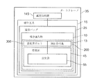
先ず図1を参照すると、未硬化の複合樹脂部品10は、以下「装入物」、「複合装入物」、「複合部品装入物」または「水平材装入物」と呼ばれる場合もある。このような装入物は、オートクレーブ内に支持されてよい。具体的には装入物10は、オートクレーブ35内に配置された硬化工具15上で硬化されてよく、その中でオートクレーブ熱および圧力が複合装入物10に加えられる。複合装入物10は、1つまたは複数の内部の空隙、閉じ込められたまたは囲まれた領域または空隙部を含み、これは記載を容易にする目的で、装入空隙部13として以下で集合的に呼ぶことにする。
Referring first to FIG. 1, the uncured
空気袋端部取付具200に作動式に結合された可撓性の膨張式空気袋55を備える空気袋システムもまた設けられている。単なる一例として、可撓性の膨張式空気袋55は、空気袋端部取付具200の一部に対して密閉されてよい。可撓性の膨張式空気袋55は、例えばオートクレーブ硬化プロセスにおいてなど、硬化プロセスにおいて装入物10に加えられる外圧に対応するために、硬化サイクルより前に硬化工具15の内部空隙部45内に配置される、あるいはその中にインサートされてよい。空気袋端部取付具200は、この構成において可撓性の膨張式空気袋55に接着される、またはこれに対して密閉されてよい。好ましい一構成において、および以下でより詳細に説明するように、空気袋端部取付具200は、概ね平坦な頂部面と概ね平坦な底部面とを備える実質的に矩形の外形を有する金属(例えばアルミニウムの)または複合材料を有する場合がある。好ましくは、空気袋端部取付具は、端部取付具の第1の面から第2の面まで延伸するボルト穴を画定する。このボルト穴は、通気用ボルト300を受けるように構成されてよい。このような通気用ボルト300は、内部を取り除いたボルトであってよく、これはまた当分野においてバンジョーボルトとも呼ばれる。好ましくは、空気袋端部取付具200はまた、端部取付具の第2の部分に沿って延伸する水平方向の穴も画定する。膨張式空気袋55の内部にあるのは端部取付具のこの第2の部分である。
An air bag system is also provided that includes a flexible
通気用ボルト300と組み合わせた空気袋端部取付具200は、通気用ボルト300が作動式に空気袋端部取付具のボルト穴に結合される際、外圧を空気袋の内部に加えることを可能にする内部経路を画定するために通気用ボルト300の内側の穴と、端部取付具の水平方向の穴とが協働して作用するように構成される。そういうものとして、真空の袋状になった硬化工具の外側にある外圧が、工具の底部側から、通気用ボルトの穴を通って空気袋端部取付具を通り、そして空気袋55へと侵入することが可能になる。したがって開示される空気袋システムは、真空バッグ25内にあらゆる種類の通気用ポートを設ける必要がなく、可撓性の膨張式空気袋55に対してオートクレーブ通気作用を提供する。よって、空気袋端部取付具200、通気用ボルト300および膨張式空気袋55が閉鎖システムを形成するために協働して作用することで、空気袋55の内部をオートクレーブ35の内部空気に直接曝すことができる。
The air bag end fitting 200 combined with the
可撓性のバッグ、例えば真空バッグ25などが、可撓性の空気袋55、空気袋端部取付具200、通気ボルトを覆うように配置され、それらを覆うように密閉され、その後硬化工具15に対して固定される。よって真空バッグ25は、複合装入物10、膨張式空気袋55、空気袋端部取付具200および通気用ボルト300の頂部を覆う真空空間を形成する。重要なことには、この空気袋システム構成において、可撓性の空気袋55の内部に外圧をもたらすために真空バッグ25内に通気用の穴は全く必要ない。可撓性のバッグ25は、可撓性のバッグ25を真空にするために好適な真空供給源145と結合されるように適合されている。
A flexible bag, such as a
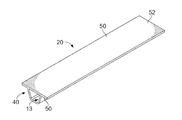
次に図2を参照すると、開示される空気袋システムおよび硬化方法は、1つまたは複数の内部空隙部を有する種々の幾何学形状の多様な複合樹脂部品を硬化させるために採用されてよい。例えばおよび限定ではなく、開示される空気袋システムおよび方法は、繊維強化複合樹脂水平材20の作製に使用される場合がある。好ましい一構成において、この水平材20は、プリプレグの複数層のレイアップであってよい。この例示の構成において、水平材20は、内部の水平材の空隙部45を形成するハット部分40と、一対の横方向に延伸するフランジ部分50と、硬化作業においてフランジ部分50と一緒に凝固されるほぼ平坦な皮膜部分52とを備える。当業者が認識するように、代替の水平材の幾何学形状が可能である。
Referring now to FIG. 2, the disclosed bladder system and curing method may be employed to cure a variety of composite resin parts of various geometries having one or more internal voids. For example and without limitation, the disclosed bladder system and method may be used to make the fiber reinforced composite resin
図3〜図11はそれぞれ、図2に示される水平材20の硬化作業のために、図1に示される装置の準備における連続する段階を示している。特に図3を参照すると、硬化工具15は、任意の好適な材料を含む。例えば特定の用途に関して、好適な硬化工具材料は、インバールなどのニッケルと鉄の合金であってよい。代替として、硬化工具は、複合材料を含む場合もある。硬化工具が複合工具である場合、ねじ山付きインサートを使用して、通気用ボルトを硬化工具にねじ込み式に取り付けることができる。
3 to 11 each show successive steps in the preparation of the apparatus shown in FIG. 1 for the curing operation of the
この例示の構成において、硬化工具15は、少なくとも1つの装入空隙部45を画定し、この装入空隙部は、水平方向に延伸する一対のフランジ部分工具面70と共にハット部分工具面65を画定することができる。好ましい一構成において、工具面65、70は、図2に示される水平材20のハット部分40と、フランジ部分50それぞれの幾何学形状にそれぞれ合致するように構成される。硬化工具15はさらに、内部空隙部45を取り囲むほぼ平坦な上部工具面80を備える。工具はさらに、空隙部45の一端における壁構造82と、壁構造82から延伸するほぼ平坦な端部部分95とを画定する。ほぼ平坦な端部部分95は、工具穴98を画定する。好ましい一構成において、この工具穴98は、端部部分95の頂面100から端部部分95の底面102まで延伸する。好ましい一構成において、この工具穴98は、図1に関して考察した通気用ボルト300などの通気ボルトを受けるように構成されてよい。加えて、および例示されるように、内部空隙部45の第1の端部は47において開放しており、この開放端は、工具穴98の位置に概ね隣接している。
In this exemplary configuration, the curing
以下で考察するように、硬化工具15は、図1を参照して概ね考察したように、複合水平材装入物を組み立て、組み立てられた装入物をオートクレーブ35内で硬化させるのに利用することができる。例示の硬化工具15は、当業者が認識するように、水平材20の特徴に合致するように適合された幾何学形状を備えるが、硬化工具15ならびに膨張式空気袋55、空気袋端部取付具200および通気用ボルト300を備える空気袋システム60は、用途および硬化すべき特定の複合部品装入物に応じて、何らかの様々な他の幾何学形状を有する硬化工具と共に使用される場合もある。単なる一例として、このような硬化工具および空気袋システムは、複数の水平材をマンドレルに沿って同時に共同で硬化させるためのシステムにおいて利用される場合もある。
As discussed below, the curing
図4を参照すると、複合水平材装入物10は、硬化工具15上に積み上げる、またはその上に置くことによってオートクレーブ内で支持することができる。例示のこの構成において、水平材装入物10は、空隙部45を満たし工具面65(図3)と係合するハット12と、工具面65にそれぞれ係合する一対の横方向に延伸するフランジ14とを備える。好ましい一構成において、水平材装入物10は、別個のレイアップ工具(図示せず)上に積み重ねられ、その後硬化工具15に移し変えられる場合もある。代替の好ましい一構成において、部品装入物10の幾何学形状および/または複雑さに応じて、硬化工具15上に直接水平材を積み重ねる場合もある。
Referring to FIG. 4, the composite
水平材装入物10が硬化工具15内に配置された後、可撓性空気袋55と、空気袋端部取付具200と、通気ボルトとを備える空気袋システム60が、硬化工具15に作動式に結合することができる。好ましい一構成において、および本明細書により詳細に記載されるように、可撓性の空気袋55は、工具の空隙部45にインサートされてよく、空気袋端部取付具200は工具穴98を覆うように位置決めされ、空気袋端部取付具200は、空隙部45の開放端部47にインサートされる。この位置において、端部取付具200は部分的に可撓性の空気袋55の中にあることになる。
After the
例えば図5は、空気袋システム60(例えば図7を参照)と共に使用され得る空気袋端部取付具200の一構成を示す。例示されるように、好ましい一構成において、空気袋端部取付具200は、第1の面取りされた表面部分210と、第2の矩形の部分220とを備える。第1の部分210は、端部取付具の第1の、すなわち底面230から端部取付具の第2の、すなわち頂面250に向かって延伸する面取りされた面212を備えることができる。さらにこの第1の部分210は、第1の面230と第2の面250の間に延伸するボルト穴260を画定する。この例示の構成において、ボルト穴260は、頂面250付近に第1の穴部分262と、第1の穴部分262の真下にある第2の穴部分264とを備える。例示されるように、第1のボルト穴部分の直径は、第2のボルト穴部分の直径と異なる。具体的には、第1の穴部分の直径は、第2のボルト穴部分の直径より大きい。このようなボルト穴構成の1つの利点は、それがバンジョー取付具またはボルトなどの内側が取り除かれたボルトなどの通気ボルトの利用を可能にする点である。このようなボルトをここで開示される空気袋システムと共に使用することの1つの利点は、例えば、複合装入物が、硬化ステップにおいてオートクレーブ内で支持される間に通常受ける高圧などの高圧用途に耐えるそれぞれの能力である。
For example, FIG. 5 illustrates one configuration of a bladder end fitting 200 that may be used with a bladder system 60 (see, eg, FIG. 7). As illustrated, in one preferred configuration, the bladder end fitting 200 includes a first chamfered
加えて、滑らかで平坦な表面を形成する座繰りされたまたは械加工された機構266もまた、ボルト穴260の底面230に沿って形成されてよい。この機械加工された機構266は、端部取付具が図3〜図4の硬化工具15のほぼ平坦な表面部分95に対して設置される際など端部取付具200が硬化工具に対して設置される際、第1の圧力密閉部材(例えば図6Cにおける第1の密閉部材150)を受けるように構成されてよい。同様のやり方において、第1の穴部分262の底面261もまた、第2の圧力密閉部材160(例えば、図6Dにおける密閉部材160)を受けるように構成されてよい。
In addition, a countersunk or machined mechanism 266 that forms a smooth, flat surface may also be formed along the
例えば図6Cは、第1の圧力密閉部材150を示しており、図6Dは、第2の密閉部材160を示している。好ましい一構成において、このような圧力密閉部材150は、エラストマー密閉リングまたは圧縮可能なOリングの形態を採る場合がある。別の好ましい構成において、圧力密閉部材150は、カリフォルニア州、ロングビーチのRubbercraftによって提供されるDuo−SealガスケットなどのガスケットのようにOリングが内側に内蔵された金属ワッシャの形態を採る場合もある。設置される際、このような圧力密閉部材は、密閉し、これにより外圧を圧力経路390(例えば図11を参照)内に適切に封じ込めるために、通気用ボルト300と端部取付具200の間、ならびに端部取付具と工具15の平坦な部分95の間で圧縮されてよい。
For example, FIG. 6C shows the first
好ましい一構成において、機械加工された機構261内に設けられた第2の圧力密閉部材160は、図6Dに示されるようにOリングが金属ワッシャの内周161上に内蔵された金属ワッシャである。好ましい一構成において、第1の穴部分262の底面261に設けられた第2の圧力密閉部材は、エラストマー密閉リングである。代替の圧力密閉部材構成もまた利用されてよい。
In a preferred configuration, the second
空気袋端部取付具200はさらに水平方向の穴280を画定する。例示されるように、水平方向の穴280は、端部取付具200の第2の部分220に水平方向に沿って、第2の穴部分264から第2の部分220の壁部分290に向かって延伸する。よってボルト穴264(すなわち第2の穴部分)と、水平方向の穴280は、互いに流体連通して存在している。また示されるように、端部取付具200の第2の端部220は、概ね矩形形状を備え、その全体の高さHSP272は端部取付具の第1の端部の全体の高さHFP270よりわずかに小さい。第2の部分220の高さが小さいことの1つの理由は、空気袋の内部をこの矩形端部220の外側面275に作動可能に結合させる、または取り付けることを可能にするためである。当業者が理解するように、異なる高さHSP272、HFP270構成もまた利用されてよい。例えば代替の一構成では、高さHSP272は、高さHFP270と等しいか、それより大きい場合もある。
The bladder end fitting 200 further defines a
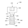
図6Aは、図5に示される端部取付具200と共に利用され得る通気用ボルト300の斜視図を示している。図6Bは、図6Aに示される通気用ボルト300の頂面図を示している。好ましい一構成において、この通気ボルトはバンジョーボルトである。
FIG. 6A shows a perspective view of a
次に図6Aおよび図6Bを参照すると、通気用ボルト300は、拡大されたヘッド開口部310を画定する拡大された通気ボルトヘッド305を備える。図6Bから分かるように、拡大されたヘッド開口部310は、通気ボルトが端部取付具200の頂面250より上に飛び出さないように(例えば図5を参照)空気袋端部取付具200の穴に配置される際、同様に成形された駆動工具が通気ボルトを硬化工具の頂面上の所定の場所に推し進めるおよび/またはねじ込むことができるように六角形に成形された開口部を備えることができる。
Referring now to FIGS. 6A and 6B, the
通気用ボルト300はさらに、拡大されたヘッド305から離れるように延伸するボルトシャフト340を備える。重要なことには、このボルトシャフト340は、ボルトシャフト340の少なくとも一部に沿って延伸する内部ボルト穴355を画定する。シャフト340はさらに、拡大されたヘッド305から直接延伸する第1のネック部分315を備える。第2のネック部分320が、第1のネック部分315から延伸し、第3のネック部分330が、この第2のネック部分320から延伸している。この第3のネック部分330は、環状の溝370に隣接して存在する。ボルトシャフト340はさらに、ねじ山360を備える接続端部350を備える。この構成において、ねじ山360は、外側のねじ山である。重要なことには、この例示される構成において、シャフト340の内部の穴355は、ボルトシャフト340の底部ボルト面380から第2のネック部分320まで延伸している。通気ボルトはさらに軸方向の通気ポート325を備える。この通気ポート325もまた、第2のネック部分320上に設けられ、内部ボルト穴355と流体整列されている。
The
次のステップにおいて、図7に示されるように、空気袋システム60が硬化工具15に対して設置される。具体的には、空気袋システム60の膨張式空気袋55が、硬化サイクルにおいて加えられる外圧に対応するために水平材装入物10の内部空隙部45内に配置される。空気袋55は、任意の好適な材料、例えばおよび限定ではなくエラストマーなどで形成されてよい。空気袋を硬化作業の後に空隙部45から取り出し易くするために、空気袋が設置される前に解放作用物または解放フィルムが空気袋55に適用される場合もある。好ましい一構成において、空気袋55は、図5に示される空気袋端部取付具200の第2の部分220(すなわち矩形の部分)と結合されるように適合される。この例において、空気袋55は、内部空隙部45の幾何学形状のほぼ合致するように構成され、硬化工具15の平坦な工具面80とほぼ同一面にあるほぼ平坦な上部面57を有する。
In the next step, the
図7にも示されるように、空気袋端部取付具200は、工具15の端部部分95に沿って配置されている。この設置位置において、空気袋端部取付具200のボルト穴260は、硬化工具15の上部面に沿って設けられたボルト穴98と整列するように位置決めされる。加えて、空気袋55は、空気袋端部取付具200に取り外せないように取り付けられ、これに対して密閉されることで、空気袋55が硬化プロセスのための準備において複合装入物10内に設置される度に空気袋55を空気袋端部ユニット200に接続し直す必要性をなくす。
As shown in FIG. 7, the air bag end fitting 200 is arranged along the
次に通気用ボルト300を空気袋端部取付具200のボルト穴260に作動式にインサートすることができる。この通気ボルトがボルト穴260にインサートされる際、通気ボルトはさらに、それが通気用ボルト300の接続端部350を工具15のボルト穴98(例えば図4を参照)にねじ込み式に接続するように所定の場所へと回転されてよい。適切にインサートされると、通気用ボルト300は、通気用ボルト300の通気ポート325が空気袋端部取付具の水平方向の穴280と整列するように空気袋端部取付具200内に位置決めされる。通気用ボルト300を所定の場所に回転させることで、通気用ボルト300と端部取付具200の間の第1の圧力密閉部材と、端部取付具と工具15の平坦な部分95の間の第2の圧力密閉部材とを圧縮することで、密閉し、これにより外圧を圧力経路390(例えば図11を参照)内に適切に封じ込める。
The
次に図8を参照すると、図7に示されるように空気袋システム60が設置された後、ほぼ平坦な複合皮膜装入物115が、硬化工具15上に置かれ、膨張式空気袋55の上にかぶさり、水平材装入物10のフランジ14(図7)および平坦な工具面80と向き合って接触する。
Referring now to FIG. 8, after the
次に図9に示されるように、当て板120が平坦な複合皮膜装入物115を覆うように設置されることで、硬化プロセスにおいて皮膜装入物115全体にわたって実質的に均一な圧力を加えることができる。また図7には示されないが、用途に応じて剥離式の層、解放フィルムおよび/または通気穴あるいは他の構成要素が当て板120と共に設置される場合がある。次に、および図10に示されるように好適なシーラントテープ125または他の好適なシーラントが、工具15の真空の袋状にするための準備において硬化工具15の外周に塗布される場合もある。この時点で真空プローブベース130が、設置された空気袋端部取付具200に隣接して硬化工具15の平坦な端部部分95に適用されてよい。次に、真空プローブ135が、真空プローブベース130上に設置されてよい。この真空プローブは、硬化サイクルにおいて真空バッグ25内の圧力を排気するまたは選択式に解放するために真空供給源145(図示せず)と結合されるように適合されてよい。
Next, as shown in FIG. 9, a
例えば好ましい空気袋システム接続の一実装形態が図11に示されている。図11は次のプロセスステップを示している。第1および第2の圧力密閉部材150、160および図10に示される通気用ボルト300の設置に続いて、ポリエステルまたはナイロンなどの好適な材料で形成された可撓性のバッグ25(真空バッグ25と呼ばれる場合もある)が、工具15を覆うように設置され、空気袋端部取付具200、通気用ボルトの拡大されたヘッド305、水平材装入物10および空気袋55を覆う。真空バッグ25は、シーラントテープ125または他の好適なシーラントを利用して硬化工具15の外周に対して、かつ真空プローブベース130を囲むように密閉される。
For example, one implementation of a preferred bladder system connection is shown in FIG. FIG. 11 shows the next process step. Following installation of the first and second
真空バッグ25の排気は、真空バッグ25を空気袋端部取付具200、通気用ボルト300の頂部、空気袋55および工具15の頂面に向けて下方に引っ張る。オートクレーブ内で行なわれる硬化ステップにおいて、オートクレーブ圧PAが真空バッグ25を硬化工具15に当たるように押しやり、これにより複合装入物10を圧縮する。加えて、オートクレーブ圧PAは通気用ボルト300の底部と通じているため、オートクレーブ圧PAもまた空気袋55の内部に加えられる。具体的には工具15の底部はオートクレーブ圧を受けるように配管され、この圧力は、通気用経路を経由して空気袋55の内部と通じることになる。圧力密閉部材150、160が、通気用ボルト300と端部取付具200の間ならびに端部取付具と工具15の平坦な部分95の間で圧縮されることで、密閉し、これにより外圧を圧力経路390中に適切に封じ込めることになる。
The
ここで考察される空気袋システム60が多数の水平材を同時に共同で硬化させるのに利用される場合、水平材の各々に対して各々別々の空気袋が、同一のオートクレーブ圧に対して配管される場合もある。このようなオートクレーブ圧PAが空気袋55の内部75に到達するために、オートクレーブ圧PAは、圧力経路390をたどることになる。このような圧力経路390は、通気用ボルト300の軸方向のポート325を経由して空気袋端部取付具200の水平方向の穴280に結合された通気用ボルト300の内部の穴355を備え、これにより空気袋55の内部をオートクレーブ圧PAによって内側から加圧する。この空気袋55の内部加圧によって、特定の力PAを複合装入物10に対して加える。したがって空気袋55がその膨張した状態を維持する間、成型される複合装入物をオートクレーブ内で硬化させることができる。これは、硬化および成型作業の合間に、複合装入物の外側面が、工具15および当て板シート115の各々の工具面に当たるように押しつけられることを確実にするのに役立つ。硬化作業が完了すると、オートクレーブ圧PAは、真空バッグ25から除去され、これにより空気袋55の内部75からも除去される。
If the
次に上記に記載した空気袋システム60を使用するオートクレーブ硬化作業のための方法400のステップを広く例示する図12に注目されたい。例えば、およびステップ402で始めると、複合樹脂装入物10が、好適な工具、本明細書で考察され例示されるような硬化工具15などの上に配置されることによってオートクレーブ内で支持される。ステップ404において、空気袋55が装入物の空隙部内に設置される。その後ステップ406において、空気袋55は、先に記載したような空気袋システム60を形成するために空気袋端部取付具200および通気用ボルト300に結合されてよい。好ましい一構成において、空気袋端部取付具200は硬化工具15の概ね平坦な頂面に取り外し可能に結合され、可撓性の膨張式空気袋55が装入物10の内部空隙部45内に設置される。通気用ボルト300の内部ボルト穴355が、空気袋端部取付具200の水平方向の穴280に流体結合されることで、オートクレーブ圧PAが空気袋55の内部75に侵入することを可能にするためにオートクレーブと空気袋55の間に圧力経路を画定する。ステップ408において、空気袋55を伴う複合装入物20、空気袋端部取付具200および通気用ボルト300の頂部は、真空バッグなどの可撓性のバッグ25によって覆われ、この可撓性のバッグはこのとき硬化工具15に対して密閉される。
Attention is now directed to FIG. 12, which broadly illustrates the steps of a
ステップ410において、複合装入物を圧縮するためにオートクレーブ圧PAがバッグ25に加えられる。加えてオートクレーブ圧PAは圧力経路390を経由して空気袋55の内部75にも加えられ、これにより空気袋55を加圧してオートクレーブ圧によって複合装入物10に加えられる力に対応する。
In
本開示の実施形態は、特に、例えば航空宇宙、船舶、自動車用途および複合部品のオートクレーブ硬化作業が利用される可能性のある他の用途を含めた輸送産業において、多様な種類の潜在的な用途における利用法を見いだす可能性がある。したがって図13および図14を次に参照すると、本開示の実施形態は、図13に示される航空機の製造および保守点検方法500ならびに図14に示される航空機550の文脈においてにおいて使用されてよい。開示される実施形態の航空機用途には、これに限定するものではなく、ほんのいくつか挙げるとすると梁、桁および水平材など補剛材の、例えば限定するものではなく硬化作業などが含まれてよい。製造の前に、例示の方法500は、航空機550の仕様および設計502と、材料調達504とを含む場合がある。製造する際、航空機550の構成要素および部分組立品の製造506ならびにシステム統合508が行なわれる。その後航空機550は、就航中512となるように認証および搬送510を受けることができる。顧客によって就航中にある間、航空機550は定期的な整備および保守点検514が予定され、これは修正、再構成、改修などを含む場合もある。
Embodiments of the present disclosure are particularly useful in various types of potential applications in the transportation industry, including, for example, aerospace, marine, automotive applications and other applications where composite part autoclave curing operations may be utilized. There is a possibility of finding usage in. Accordingly, with reference now to FIGS. 13 and 14, the embodiments of the present disclosure may be used in the context of the aircraft manufacturing and
方法500のプロセスは各々、システム統合者、第3者および/またはオペレータ(例えば顧客)によって実行される、または行なわれてよい。この記載の目的に関して、システム統合者には、限定するのではなく、任意の数の航空機の製造元および主要なシステムの下請け業者が含まれてよく、第3者には、限定するのはなく任意の数の供給業者、下請け業者および部品供給元が含まれてよく、オペレータには、エアライン、リース会社、軍事団体、サービス組織などが含まれてよい。
Each of the processes of
図14に示されるように、例示の方法500によって形成された航空機550は、複数のシステム554を備えた機体552と、内部556とを含むことができる。ハイレベルシステム554の例には、1つまたは複数の推進システム518、電気システム520、油圧システム522および環境システム524が含まれる。任意の数の他のシステムが含まれる場合もある。航空宇宙の一例が示されているが、本開示の原理は、他の産業、例えば船舶および自動車産業に適用される場合もある。
As shown in FIG. 14, an
本明細書で具現化されるシステムおよび方法は、製造および保守点検方法500の1つまたは複数の段階において採用されてよい。例えば、製造プロセス502に相当する構成要素または部分組立品は、航空機550が就航中に形成される構成要素または部分組立品と同様のやり方で作製または製造されてよい。また1つまたは複数の装置実施形態、方法実施形態またはそれらの組み合わせが、例えば航空機550の組み立てを実質的に早める、または航空機550のコストを抑えることによって製造段階502および504において利用される場合もある。同様に、1つまたは複数の装置実施形態、方法実施形態またはそれらの組み合わせが、航空機550が就航中に、例えば限定するものではなく整備および保守点検514に対して利用される場合もある。さらに本開示は以下の項による実施形態を有する。
The systems and methods embodied herein may be employed at one or more stages of manufacturing and
項1.内部空隙部を有する複合装入物の硬化作業において利用するための装置であって、
オートクレーブ硬化作業において複合装入物に対して圧力を加えるために空隙部内に配置されるように適合された可撓性の空気袋と、
可撓性の空気袋に作動式に結合され、ボルト穴と水平方向の穴とを画定する端部取付具とを備え、
端部取付具のボルト穴に通気ボルトが作動式に結合される際、通気ボルトと水平方向の穴が、空気袋の内部が外圧を受けることを可能にする圧力経路を画定する、装置。
Item 1. An apparatus for use in a curing operation of a composite charge having an internal void,
A flexible bladder adapted to be placed in the cavity to apply pressure to the composite charge in an autoclave curing operation;
An end fitting operably coupled to the flexible bladder and defining a bolt hole and a horizontal hole;
The apparatus wherein the vent bolt and the horizontal hole define a pressure path that allows the interior of the bladder to receive external pressure when the vent bolt is operatively coupled to the bolt hole of the end fitting.
項2.可撓性の空気袋、端部取付具および通気ボルトを覆うように密閉された可撓性のバッグをさらに備える、項1の装置。 Item 2. The apparatus of claim 1, further comprising a flexible bag sealed to cover the flexible bladder, the end fitting, and the vent bolt.
項3.複合装入物を上に配置させるように適合された硬化工具をさらに備え、
可撓性の空気袋が、複合装入物上に配置され、可撓性のバッグが硬化工具に対して密閉される、項2の装置。
Item 3. Further comprising a curing tool adapted to place the composite charge on top,
The apparatus of paragraph 2, wherein a flexible bladder is disposed on the composite charge and the flexible bag is sealed against the curing tool.
項4.硬化工具が複合硬化工具である項3の装置。 Item 4. Item 4. The apparatus according to Item 3, wherein the curing tool is a composite curing tool.
項5.端部取付具のボルト穴が、硬化工具の合致面に沿って設けられた工具穴と整列するように位置決めされる、項4の装置。 Item 5. Item 5. The apparatus of clause 4, wherein the bolt holes in the end fitting are positioned to align with tool holes provided along the mating surface of the curing tool.
項6.通気ボルトが、端部取付具のボルト穴にインサートされ、
通気ボルトが、通気ボルトが工具穴にねじ込み式に接続するように所定の場所に回転される、項4の装置。
Item 6. A ventilation bolt is inserted into the bolt hole of the end fitting,
The apparatus of paragraph 4, wherein the ventilation bolt is rotated into place such that the ventilation bolt is screwed into the tool hole.
項7.通気ボルトが、端部取付具のボルト穴にインサートされ、
通気ボルトが、通気ボルトが工具穴の中に設けられたねじ込み式のインサートにねじ込み式に接続するように所定の場所に回転される、項5の装置。
Item 7. A ventilation bolt is inserted into the bolt hole of the end fitting,
6. The apparatus of clause 5, wherein the ventilation bolt is rotated into place so that the ventilation bolt is threadedly connected to a threaded insert provided in the tool hole.
項8.端部取付具のボルト穴が、端部取付具の第1の面から第2の面まで延伸する、項1の装置。 Item 8. The apparatus of paragraph 1, wherein the bolt holes in the end fitting extend from the first surface to the second surface of the end fitting.
項9.工具が、可撓性バッグ内で選択的に圧力を解放するために真空供給源と結合されるように適合された真空ポートを備える、項3の装置。 Item 9. The apparatus of claim 3, wherein the tool comprises a vacuum port adapted to be coupled with a vacuum source to selectively relieve pressure within the flexible bag.
項10.端部取付具のボルト穴が、
第1のボルト穴部分および第2のボルト穴部分とを備え、
第1のボルト穴部分の直径が第2のボルト穴部分の直径と異なる、項1の装置。
A first bolt hole portion and a second bolt hole portion;
The apparatus of paragraph 1, wherein the diameter of the first bolt hole portion is different from the diameter of the second bolt hole portion.
項11.第1のボルト穴部分の直径が第2のボルト穴部分の直径より大きい、項10の装置。
項12.通気ボルトの内部のボルト穴と、端部取付具の水平方向の穴が、空気袋の内部が外圧を受けることができるように圧力経路を画定する、項1の装置。
項13.通気用ボルトと端部取付具の間に位置決めされた第1の圧力密閉部材をさらに備え、
第1の密閉部材が、外圧を圧力経路内に封じ込める、項3の装置。
The apparatus of paragraph 3, wherein the first sealing member contains the external pressure in the pressure path.
項14.端部取付具と工具の間に位置決めされた第2の圧力密閉部材をさらに備え、
第2の密閉部材が、外圧を圧力経路内に封じ込める、項13の装置。
項15.内部空隙部を有する複合装入物を硬化させる方法であって、
複合装入物を硬化工具上で支持するステップと、
複合装入物内に空気袋を設置するステップと、
空気袋を空気袋端部取付具に結合するステップと、
通気ボルトを利用して空気袋端部取付具を硬化工具に固定するステップとを含み、
通気ボルトと、空気袋端部取付具が、空気袋の内部に外圧を供給するための圧力経路を画定する方法。
Supporting the composite charge on a curing tool;
Installing an air bag within the composite charge;
Coupling the bladder to the bladder end fitting;
Securing the bladder end fitting to the curing tool using a ventilation bolt,
A method wherein the vent bolt and the bladder end fitting define a pressure path for supplying external pressure to the interior of the bladder.
項16.通気ボルトと空気袋端部取付具によって画定された圧力経路を経由して空気袋の内部を外圧に曝すことによって空気袋を加圧するステップをさらに含む、項15の方法。
Item 16. 16. The method of
項17.空気袋端部取付具が、空気袋の内部に対して密閉される、項15の方法。
Item 17. Item 16. The method of
項18.空気袋、空気袋端部取付具および通気ボルトヘッドを覆うように可撓性のバッグを密閉するステップをさらに含む、項17の方法。 Item 18. Item 18. The method of Item 17, further comprising the step of sealing the flexible bag over the bladder, bladder end fitting, and vent bolt head.
項19.硬化工具を複合装入物を上に配置させるように適合させるステップをさらに含み、
空気袋が、複合装入物の空隙部内に配置される、項18の方法。
Item 19. Further comprising adapting the curing tool to place the composite charge on top,
Item 19. The method of Item 18, wherein the bladder is disposed within the void of the composite charge.
項20.可撓性バッグを硬化工具に対して密閉するステップをさらに含む、項19の方法。
項21.第1の圧力密閉部材を通気用ボルトと端部取付具の間に位置決めすることで、第1の密閉部材が、圧力経路内に外圧を封じ込めるステップをさらに含む、項20の方法。
Item 21. 21. The method of
項22.第2の圧力密閉部材を端部取付具と工具の間に位置決めすることで、第2の密閉部材が、圧力経路内に外圧を封じ込めるステップをさらに含む、項21の方法。 Item 22. Item 22. The method of Item 21, further comprising the step of positioning the second pressure sealing member between the end fitting and the tool so that the second sealing member contains an external pressure in the pressure path.
種々の有利な実施形態の記載は、例示および記述する目的で提示されており、これは網羅的である、または開示される形態に限定されることは意図されていない。多くの修正形態および変形形態が、当業者には明らかであろう。さらに種々の有利な実施形態は、他の有利な実施形態と比べて異なる利点を提供する可能性がある。選択された1つまたは複数の実施形態は、実施形態の原理、すなわち実際の用途を最適に説明するため、および企図される特定の利用に適合されるように、他の当業者が種々の修正形態と併せて種々の実施形態に関する開示を理解することを可能にするために選択され記載されている。 The description of the various advantageous embodiments is presented for purposes of illustration and description, and is not intended to be exhaustive or limited to the forms disclosed. Many modifications and variations will be apparent to practitioners skilled in this art. Furthermore, various advantageous embodiments may provide different advantages compared to other advantageous embodiments. The selected embodiment or embodiments may be modified by various skilled artisans in order to best illustrate the principles of the embodiment, ie, the actual application, and to be adapted to the particular application contemplated. It has been chosen and described to enable understanding of the disclosure relating to the various embodiments in conjunction with the forms.
10 複合装入物(複合装入物、複合部品装入物、水平材装入物)
12 ハット
13 装入空隙部
14 フランジ
15 硬化工具
20 繊維強化複合樹脂水平材
25 真空バッグ
35 オートクレーブ
40 ハット部分
45 空隙部
47 開放端部
50 フランジ部分
52 皮膜部分
55 空気袋
57 上部面
60 空気袋システム
65、70 工具面
75 内部
80 上部工具面
82 壁構造
95 端部部分
98 工具穴
100 頂面
102 底面
115 皮膜装入物
120 当て板
125 シーラントテープ
130 真空プローブベース
135 真空プローブ
145 真空供給源
150 第1の圧力密閉部材
160 第2の圧力密閉部材
161 内周
200 空気袋端部取付具
210 第1の部分
212 面取りされた面
220 第2の部分
230 底面
250 頂面
260 ボルト穴
261 機械加工された機構
262 第1の部分
264 第2の部分
266 機械加工された機構
270 第1の端部の全体の高さ
272 第2の端部の全体の高さ
275 外側面
280 水平方向の穴
290 壁部分
300 通気用ボルト
305 拡大された通気ボルトヘッド
310 ヘッド開口部
315 第1のネック部分
320 第2のネック部分
325 通気ポート
330 第3のネック部分
340 ボルトシャフト
350 接続端部
355 内部ボルト穴
360 ねじ山
370 環状の溝
380 底部のボルト面
390 圧力経路
400 方法
402 ステップ
404 ステップ
406 ステップ
408 ステップ
410 ステップ
500 航空機の製造および保守点検方法
502 仕様および設計
504 材料調達
506 構成要素および部分組立品の製造
508 システム統合
510 認証および搬送
512 就航中
514 整備および保守点検
518 推進システム
520 電気システム
522 油圧システム
524 環境システム
550 航空機
552 機体
554 システム
556 内部
PA オートクレーブ圧
HFP 第1の端部の全体の高さ
HSP 第2の端部の全体の高さ
10 Composite charge (Composite charge, Composite part charge, Horizontal material charge)
12 Hat 13 Loading gap 14 Flange 15 Curing tool 20 Fiber reinforced composite resin horizontal material 25 Vacuum bag 35 Autoclave 40 Hat part 45 Gap 47 Open end 50 Flange part 52 Film part 55 Air bag 57 Upper surface 60 Air bag system 65, 70 Tool surface 75 Inside 80 Upper tool surface 82 Wall structure 95 End portion 98 Tool hole 100 Top surface 102 Bottom surface 115 Coating charge 120 Pad plate 125 Sealant tape 130 Vacuum probe base 135 Vacuum probe 145 Vacuum supply source 150 First 1st pressure sealing member 160 2nd pressure sealing member 161 inner circumference 200 air bag end fitting 210 first part 212 chamfered surface 220 second part 230 bottom surface 250 top surface 260 bolt hole 261 machined Mechanism 262 first part 264 Second portion 266 Machined mechanism 270 Overall height of first end 272 Overall height of second end 275 External surface 280 Horizontal hole 290 Wall portion 300 Ventilation bolt 305 Enlarge Ventilated bolt head 310 Head opening 315 First neck portion 320 Second neck portion 325 Vent port 330 Third neck portion 340 Bolt shaft 350 Connection end 355 Internal bolt hole 360 Screw thread 370 Annular groove 380 Bottom Bolt surface 390 pressure path 400 method 402 step 404 step 406 step 408 step 410 step 500 aircraft manufacturing and service method 502 specification and design 504 material procurement 506 component and subassembly manufacturing 508 system integration 510 certification and transport 512 flying in 514 maintenance and maintenance 518 propulsion system 520 electrical system 522 hydraulic system 524 environment system 550 aircraft 552 fuselage 554 System 556 internal P A autoclave pressure H FP total height H SP second end of the first end portion Overall height of the part
Claims (10)
オートクレーブ硬化作業において前記複合装入物(10)に対して圧力を加えるために前記内部空隙部(45)内に配置されるように適合された可撓性の空気袋(55)と、
前記可撓性の空気袋(55)に作動式に結合され、第1の穴であるボルト穴(260)と水平方向の第2の穴(280)とを画定する端部取付具(200)とを備え、
前記端部取付具(200)の前記ボルト穴(260)に通気ボルト(300)が作動式に結合される際、前記通気ボルト(300)と前記水平方向の穴(280)が、前記空気袋(55)の内部が外圧を受けることを可能にする圧力経路(390)を画定し、
前記装置が、
前記複合装入物(10)を上に配置させるように適合された硬化工具(15)をさらに備え、
前記可撓性の空気袋(55)が、前記複合装入物(10)上に配置され、
前記端部取付具(200)の前記ボルト穴(260)が、前記硬化工具(15)の合致面に沿って設けられた工具穴(98)と整列するように位置決めされており、
前記可撓性の空気袋(55)、前記端部取付具(200)および前記通気ボルト(300)を覆うように密閉された可撓性のバッグ(25)をさらに備え、
前記可撓性のバッグ(25)が前記硬化工具(15)に対して密閉され、
前記通気ボルト(300)が、前記端部取付具(200)の前記ボルト穴(260)にインサートされ、
前記通気ボルト(300)が、前記通気ボルトが前記工具穴(98)にねじ込み式に接続するように所定の場所に回転され、
前記通気ボルト(300)と前記端部取付具(200)の間に位置決めされた第1の圧力密閉部材(150)をさらに備え、
前記第1の圧力密閉部材(150)が、前記外圧を前記圧力経路(390)内に封じ込め、
前記端部取付具(200)と前記硬化工具(15)の間に位置決めされた第2の圧力密閉部材(160)をさらに備え、
前記第2の圧力密閉部材(160)が、前記外圧を前記圧力経路(390)内に封じ込めることを特徴とする、装置。 A device for use in the curing operation of a composite charge (10) having an internal void (45),
A flexible bladder (55) adapted to be placed in the internal cavity (45) for applying pressure to the composite charge (10) in an autoclave curing operation;
An end fitting (200) operatively coupled to the flexible bladder (55) and defining a first hole, a bolt hole (260) and a horizontal second hole (280). And
When the ventilation bolt (300) is operatively coupled to the bolt hole (260) of the end fitting (200), the ventilation bolt (300) and the horizontal hole (280) are connected to the air bag. Defining a pressure path (390) that allows the interior of (55) to receive external pressure;
The device is
Further comprising a curing tool (15) adapted to position said composite charge (10) on top thereof;
The flexible bladder (55) is disposed on the composite charge (10);
The bolt hole (260) of the end fitting (200) is positioned to align with a tool hole (98) provided along a mating surface of the hardening tool (15) ;
A flexible bag (25) hermetically sealed to cover the flexible bladder (55), the end fitting (200) and the vent bolt (300);
The flexible bag (25) is sealed against the curing tool (15);
The ventilation bolt (300) is inserted into the bolt hole (260) of the end fitting (200);
The vent bolt (300) is rotated into place so that the vent bolt is screwed into the tool hole (98);
A first pressure sealing member (150) positioned between the ventilation bolt (300) and the end fitting (200);
The first pressure sealing member (150) contains the external pressure in the pressure path (390);
A second pressure sealing member (160) positioned between the end fitting (200) and the curing tool (15);
Device, wherein the second pressure sealing member (160) contains the external pressure in the pressure path (390) .
前記通気ボルト(300)が、前記通気ボルトが前記工具穴(98)の中に設けられたねじ込み式のインサートにねじ込み式に接続するように所定の場所に回転される、請求項1に記載の装置。 The ventilation bolt (300) is inserted into the bolt hole (260) of the end fitting (200);
The vent screw (300), said vent bolt is rotated into place to connect to screw-threadedly insert provided in said tool bore (98) of claim 1 apparatus.
前記複合装入物(10)を硬化工具(15)上で支持するステップ(420)と、
前記複合装入物(10)内に空気袋(55)を設置するステップ(404)と、
前記空気袋(55)を空気袋端部取付具(200)に結合するステップ(406)と、
通気ボルト(300)を利用して前記空気袋端部取付具(200)を前記硬化工具(15)に固定するステップとを含み、
前記通気ボルト(300)と、前記空気袋端部取付具(200)が、前記空気袋の内部に外圧を供給するための圧力経路(390)を画定する方法。 A method (400) for curing a composite charge (10) having an internal void (45) using the apparatus according to any one of claims 1-4 .
Supporting the composite charge (10) on a curing tool (15) (420);
Installing an air bag (55) in the composite charge (10) (404);
Coupling (406) the bladder (55) to a bladder end fitting (200);
Securing the bladder end fitting (200) to the curing tool (15) using a ventilation bolt (300);
The method wherein the vent bolt (300) and the bladder end fitting (200) define a pressure path (390) for supplying external pressure to the interior of the bladder.
前記空気袋(55)が、前記複合装入物(10)の空隙部(45)内に配置される、請求項8に記載の方法。 Further comprising the step of adapting the curing tool (15) to place the composite charge (10) thereon;
The method of claim 8 , wherein the bladder (55) is disposed within a void (45) of the composite charge (10).
Applications Claiming Priority (2)
| Application Number | Priority Date | Filing Date | Title |
|---|---|---|---|
| US14/450,947 | 2014-08-04 | ||
| US14/450,947 US9914244B2 (en) | 2014-08-04 | 2014-08-04 | Bladder system for curing composite parts |
Publications (3)
| Publication Number | Publication Date |
|---|---|
| JP2016034749A JP2016034749A (en) | 2016-03-17 |
| JP2016034749A5 JP2016034749A5 (en) | 2018-08-02 |
| JP6594674B2 true JP6594674B2 (en) | 2019-10-23 |
Family
ID=53488201
Family Applications (1)
| Application Number | Title | Priority Date | Filing Date |
|---|---|---|---|
| JP2015125396A Active JP6594674B2 (en) | 2014-08-04 | 2015-06-23 | Air bag system for curing composite parts |
Country Status (5)
| Country | Link |
|---|---|
| US (1) | US9914244B2 (en) |
| EP (1) | EP2982496B1 (en) |
| JP (1) | JP6594674B2 (en) |
| KR (1) | KR102347455B1 (en) |
| CN (1) | CN105313349B (en) |
Families Citing this family (4)
| Publication number | Priority date | Publication date | Assignee | Title |
|---|---|---|---|---|
| US20160339682A1 (en) * | 2015-05-18 | 2016-11-24 | The Boeing Company | Bladder System for Curing Composite Parts |
| CN105904742B (en) * | 2016-04-25 | 2018-09-04 | 大连理工大学 | A kind of winding, molding method of full composite material shell |
| US10751955B2 (en) | 2017-04-10 | 2020-08-25 | The Boeing Company | Unitized composite structure manufacturing system |
| US10960619B2 (en) * | 2019-04-08 | 2021-03-30 | The Boeing Company | Hollow bladder repair process |
Family Cites Families (21)
| Publication number | Priority date | Publication date | Assignee | Title |
|---|---|---|---|---|
| US5037599A (en) * | 1989-06-26 | 1991-08-06 | Basf Aktiengesellschaft | Single diaphragm forming of drapeable thermoplastic impregnated composite materials |
| US5116216A (en) * | 1991-02-28 | 1992-05-26 | The United States Of America As Represented By The Secretary Of The Navy | Apparatus for preparing thermoplastic composites |
| DE4116169A1 (en) | 1991-05-17 | 1992-11-19 | Bosch Gmbh Robert | DEVICE FOR ADJUSTING THE TURNING ANGLE ASSIGNMENT OF A CAMSHAFT TO YOUR DRIVE ELEMENT |
| US5366684A (en) | 1992-12-31 | 1994-11-22 | Grumman Aerospace Corporation | Molding composite method using an inflatable bladder pressurized in an autoclave |
| US6685232B2 (en) | 2001-09-06 | 2004-02-03 | Franklin Fastener Company | Banjo clip for flange head flow bolt |
| DE102006035619B3 (en) * | 2006-07-31 | 2007-11-29 | Airbus Deutschland Gmbh | Connector for delivery of pressure medium to form core used in the manufacture of aerospace composite components |
| US8834782B2 (en) | 2007-08-07 | 2014-09-16 | William L. Rodman | Composite structures and methods of making same |
| JP5088213B2 (en) * | 2008-04-09 | 2012-12-05 | トヨタ自動車株式会社 | Internal pressure forming device |
| US9327467B2 (en) | 2008-07-10 | 2016-05-03 | The Boeing Company | Composite mandrel for autoclave curing applications |
| US9238335B2 (en) | 2008-07-10 | 2016-01-19 | The Boeing Company | Mandrel for autoclave curing applications |
| DE102008044069B3 (en) * | 2008-11-26 | 2010-08-05 | Airbus Deutschland Gmbh | Shaped body for producing a fiber composite component |
| US8293051B2 (en) | 2008-12-10 | 2012-10-23 | The Boeing Company | Method for producing composite laminates using a collapsible mandrel |
| US8074694B2 (en) | 2009-05-28 | 2011-12-13 | The Boeing Company | Stringer transition method |
| JP5588645B2 (en) * | 2009-09-15 | 2014-09-10 | 川崎重工業株式会社 | Jig for manufacturing a composite material structure having a thick portion in a cross section |
| JP5416554B2 (en) * | 2009-11-06 | 2014-02-12 | 川崎重工業株式会社 | Jig for manufacturing composite material structures |
| US8430984B2 (en) | 2010-05-11 | 2013-04-30 | The Boeing Company | Collapsible mandrel employing reinforced fluoroelastomeric bladder |
| DE102010024120B4 (en) | 2010-06-17 | 2014-10-23 | Premium Aerotec Gmbh | support profile |
| US8292332B2 (en) | 2011-01-13 | 2012-10-23 | Private Brand Tools (Australia) Pty Ltd | Swivel connector |
| US8556618B2 (en) | 2011-04-07 | 2013-10-15 | Spirit Aerosystems, Inc. | Method and bladder apparatus for forming composite parts |
| US9381704B2 (en) | 2012-06-08 | 2016-07-05 | The Boeing Company | Non-vented bladder system for curing composite parts |
| US9333713B2 (en) * | 2012-10-04 | 2016-05-10 | The Boeing Company | Method for co-curing composite skins and stiffeners in an autoclave |
-
2014
- 2014-08-04 US US14/450,947 patent/US9914244B2/en active Active
-
2015
- 2015-06-22 EP EP15173173.4A patent/EP2982496B1/en active Active
- 2015-06-23 JP JP2015125396A patent/JP6594674B2/en active Active
- 2015-07-16 KR KR1020150101055A patent/KR102347455B1/en active IP Right Grant
- 2015-07-29 CN CN201510454014.5A patent/CN105313349B/en active Active
Also Published As
| Publication number | Publication date |
|---|---|
| CN105313349B (en) | 2019-03-01 |
| CN105313349A (en) | 2016-02-10 |
| US9914244B2 (en) | 2018-03-13 |
| JP2016034749A (en) | 2016-03-17 |
| EP2982496A1 (en) | 2016-02-10 |
| KR20160016607A (en) | 2016-02-15 |
| EP2982496B1 (en) | 2018-08-08 |
| US20160031167A1 (en) | 2016-02-04 |
| KR102347455B1 (en) | 2022-01-04 |
Similar Documents
| Publication | Publication Date | Title |
|---|---|---|
| US10040256B2 (en) | Non-vented bladder system for curing composite parts | |
| US8333864B2 (en) | Compaction of prepreg plies on composite laminate structures | |
| JP6594674B2 (en) | Air bag system for curing composite parts | |
| JP6659749B2 (en) | Composite tool with vacuum integrity and method of manufacturing the same | |
| JP6043542B2 (en) | Monolithically reinforced reusable vacuum bag and method for manufacturing the same | |
| US20110146906A1 (en) | Double Vacuum Cure Processing of Composite Parts | |
| KR102207476B1 (en) | Sealing and testing segmented tools | |
| JP6181190B2 (en) | Method and apparatus for co-curing composite skin and composite stiffener in an autoclave | |
| US9925697B2 (en) | Method for bladder repair during composite part curing | |
| US9862154B2 (en) | Apparatuses and methods for efficient sealing of vacuum bag seams | |
| US9227384B2 (en) | Pressure debulking system | |
| JP2021151771A (en) | Method and device for supporting a variety of different pre-cured composite stringers | |
| US20220332060A1 (en) | Apparatus and method for processing a composite structure | |
| US20190061285A1 (en) | Fibre Composite Component Having An Elastomer Seal And A Method Of Production Thereof |
Legal Events
| Date | Code | Title | Description |
|---|---|---|---|
| A521 | Request for written amendment filed |
Free format text: JAPANESE INTERMEDIATE CODE: A523 Effective date: 20180621 |
|
| A621 | Written request for application examination |
Free format text: JAPANESE INTERMEDIATE CODE: A621 Effective date: 20180621 |
|
| A131 | Notification of reasons for refusal |
Free format text: JAPANESE INTERMEDIATE CODE: A131 Effective date: 20190318 |
|
| A977 | Report on retrieval |
Free format text: JAPANESE INTERMEDIATE CODE: A971007 Effective date: 20190320 |
|
| A521 | Request for written amendment filed |
Free format text: JAPANESE INTERMEDIATE CODE: A523 Effective date: 20190617 |
|
| TRDD | Decision of grant or rejection written | ||
| A01 | Written decision to grant a patent or to grant a registration (utility model) |
Free format text: JAPANESE INTERMEDIATE CODE: A01 Effective date: 20190826 |
|
| A61 | First payment of annual fees (during grant procedure) |
Free format text: JAPANESE INTERMEDIATE CODE: A61 Effective date: 20190925 |
|
| R150 | Certificate of patent or registration of utility model |
Ref document number: 6594674 Country of ref document: JP Free format text: JAPANESE INTERMEDIATE CODE: R150 |
|
| R250 | Receipt of annual fees |
Free format text: JAPANESE INTERMEDIATE CODE: R250 |
|
| R250 | Receipt of annual fees |
Free format text: JAPANESE INTERMEDIATE CODE: R250 |