JP6163779B2 - Element folding method and element folding apparatus - Google Patents
Element folding method and element folding apparatus Download PDFInfo
- Publication number
- JP6163779B2 JP6163779B2 JP2013027613A JP2013027613A JP6163779B2 JP 6163779 B2 JP6163779 B2 JP 6163779B2 JP 2013027613 A JP2013027613 A JP 2013027613A JP 2013027613 A JP2013027613 A JP 2013027613A JP 6163779 B2 JP6163779 B2 JP 6163779B2
- Authority
- JP
- Japan
- Prior art keywords
- wafer
- opening
- wafer mounting
- length
- folding
- Prior art date
- Legal status (The legal status is an assumption and is not a legal conclusion. Google has not performed a legal analysis and makes no representation as to the accuracy of the status listed.)
- Expired - Fee Related
Links
Images


Landscapes
- Piezo-Electric Or Mechanical Vibrators, Or Delay Or Filter Circuits (AREA)
- Dicing (AREA)
Description
本発明は、素子の折り取り方法および素子折り取り装置に関する。 The present invention relates to an element folding method and an element folding apparatus.
従来から、半導体素子(IC)あるいは圧電振動素子などを製造する方法として、一般的にウェハーと呼ばれる基板に、複数の素子をフォトリソグラフィー技術などによって形成し、この基板の形態で配線や電極などを形成した後に、基板から各素子をダイシングあるいは折り取りによって個片化して素子単体を得る方法が知られている。中でも、折り取りにより個片化する方法は、特別な装置や工程を必要とせず、低コストで製造する方法として多用されている。
しかし、近年の前述の素子を用いたデバイスの小型・薄型化の要求に伴い、素子の小型化が図られ、手動による折り取りでは、工数が増大し低コスト化が図れないという問題があった。
そのため、特許文献1では、ウェハーに形成された複数の素子に対向する折り取りピンを有し、その折り取りピンを素子に押し当てウェハーから複数の素子を同時に折り取ると共に、折り取った複数の素子を以降の作業工程に利用し易いようにして、作業効率を向上できる素子の折り取り方法や素子折り取り装置が開示されている。
Conventionally, as a method of manufacturing a semiconductor element (IC) or a piezoelectric vibration element, a plurality of elements are formed on a substrate generally called a wafer by a photolithography technique, and wiring, electrodes, etc. are formed in the form of this substrate. There is known a method of obtaining a single element by forming each element from a substrate by dicing or breaking after formation. In particular, the method of dividing into pieces by folding is not widely required as a method of manufacturing at low cost without requiring a special device or process.
However, along with recent demands for smaller and thinner devices using the aforementioned elements, there has been a problem that the elements have been reduced in size, and manual folding has increased man-hours and cost reduction cannot be achieved. .
For this reason, in Patent Document 1, there are folding pins opposed to a plurality of elements formed on the wafer, the folding pins are pressed against the elements, and the plurality of elements are simultaneously folded from the wafer. An element folding method and an element folding apparatus that can improve the working efficiency by making the element easy to use in subsequent work processes are disclosed.
しかし、折り取りピンを素子に直接押し当てることで、ウェハーから素子を折り取るため、素子に形成された電極を傷つけてしまい素子の特性が劣化するという問題があった。 However, since the element is broken from the wafer by directly pressing the folding pin against the element, there is a problem that the electrode formed on the element is damaged and the characteristics of the element deteriorate.
本発明は、上述の課題の少なくとも一部を解決するためになされたものであり、以下の形態又は適用例として実現することが可能である。 SUMMARY An advantage of some aspects of the invention is to solve at least a part of the problems described above, and the invention can be implemented as the following forms or application examples.
[適用例1]本適用例に係る素子の折り取り方法は、素子を支持しているウェハーと、第1の開口部を有しているウェハー載置部と前記ウェハー載置部の前記第1の開口部よりも前記素子の長辺方向に沿った長さが短い第2の開口部を有しているウェハー押さえ部とを備えた素子折り取り装置と、を準備する工程と、前記ウェハー載置部と前記ウェハーと前記ウェハー押さえ部とを平面視で、前記素子が前記ウェハー載置部の前記第1の開口部の外縁の内側に位置し、且つ、前記ウェハー載置部の前記第1の開口部と前記ウェハー押さえ部の前記第2の開口部との中心がずれるような位置に、前記ウェハー載置部と前記ウェハーと前記ウェハー押さえ部とを積層し配置する工程と、前記素子に対して前記ウェハー押さえ部側よりも前記ウェハー載置部側の気圧を低くして、前記ウェハーから前記素子を折り取る工程と、を含むことを特徴とする。 Application Example 1 An element folding method according to this application example includes a wafer supporting an element, a wafer mounting part having a first opening, and the first of the wafer mounting part. Preparing a device folding device including a wafer pressing portion having a second opening portion having a shorter length along the long side direction of the device than the opening portion of the wafer, and mounting the wafer The device is positioned inside the outer edge of the first opening of the wafer mounting unit in the plan view of the mounting unit, the wafer, and the wafer pressing unit, and the first of the wafer mounting unit Laminating and arranging the wafer mounting portion, the wafer and the wafer pressing portion at a position where the center of the opening of the wafer and the second opening of the wafer pressing portion is shifted, and the element On the other hand, the wafer is more than the wafer holding part side. The pressure of the mounting portion side and lower, characterized in that it comprises the steps of break off the device from the wafer.
本適用例によれば、ウェハー載置部の第1の開口部の素子の長辺方向に沿った長さがウェハー押さえ部の第2の開口部の素子の長辺方向に沿った長さより長くした構成とすることで、ウェハー載置部側からウェハーを吸引した場合、ウェハー載置部側をより気圧を低くすることができるため、素子を折り取りし易くできるという効果がある。また、ウェハー載置部の第1の開口部とウェハー押さえ部の第2の開口部との中心をずれるように配置し、特に、ウェハー押さえ部の開口部を素子のウェハーとの支持部とは反対側の先端部側へずれるように配置することで、ウェハー載置部側から吸引した場合、素子の先端部がより気圧が低くなりウェハー載置部側への変位量が大きくなるため、素子をより折り取りし易くできるという効果がある。 According to this application example, the length along the long side direction of the element of the first opening portion of the wafer mounting portion is longer than the length along the long side direction of the element of the second opening portion of the wafer holding portion. With this configuration, when the wafer is sucked from the wafer mounting portion side, the pressure on the wafer mounting portion side can be further lowered, so that the element can be easily broken off. Further, the first opening portion of the wafer mounting portion and the second opening portion of the wafer holding portion are arranged so as to be shifted from each other, and in particular, the opening portion of the wafer holding portion is a support portion for the wafer of the element. By disposing it so as to shift to the tip side on the opposite side, when sucked from the wafer mounting part side, the pressure at the tip part of the element becomes lower and the amount of displacement to the wafer mounting part side becomes larger. There is an effect that can be more easily broken.
[適用例2]上記適用例に記載の素子の折り取り方法において、前記折り取る工程では、前記ウェハー載置部側から前記素子を吸引して前記素子を折り取ることを特徴とする。 Application Example 2 In the element folding method according to the application example described above, in the folding step, the element is sucked from the wafer mounting portion side to break the element.
本適用例によれば、ウェハー載置部側から吸引して気圧を低くすることにより、素子がウェハー載置部側へ変位し、ウェハーとの支持部に応力が集中するので、素子を折り取りし易くできるという効果がある。 According to this application example, since the element is displaced to the wafer mounting part side by sucking from the wafer mounting part side and lowering the atmospheric pressure, the stress is concentrated on the supporting part with the wafer. There is an effect that it is easy to do.
[適用例3]上記適用例に記載の素子の折り取り方法において、前記ウェハー載置部と前記ウェハーと前記ウェハー押さえ部とを積層する方向の平面視で、前記ウェハー押さえ部の前記第2の開口部が前記素子と前記ウェハーとの支持部とは反対側の前記素子の端部側に配置することを特徴とする。 [Application Example 3] In the element folding method according to the application example described above, the second of the wafer pressing unit in a plan view in a direction in which the wafer mounting unit, the wafer, and the wafer pressing unit are stacked. The opening is arranged on the end side of the element opposite to the support portion between the element and the wafer.
本適用例によれば、ウェハー押さえ部の第2の開口部が素子とウェハーとの支持部とは反対側の素子の端部側に配置することで、ウェハー載置部側からウェハーを吸引した場合、素子の先端部がより気圧が低くなり変位量が大きくなるため、素子をより折り取りし易くできるという効果がある。 According to this application example, the wafer is sucked from the wafer mounting portion side by disposing the second opening of the wafer pressing portion on the end portion side of the element opposite to the support portion between the element and the wafer. In this case, since the tip of the element has a lower atmospheric pressure and a larger displacement, the element can be more easily folded.
[適用例4]上記適用例に記載の素子の折り取り方法において、前記ウェハー押さえ部の前記第2の開口部の前記素子の長辺方向に沿った長さは、前記ウェハー載置部の前記第1の開口部の前記素子の長辺方向に沿った長さの1/2以上3/4以下の範囲内であることを特徴とする。 Application Example 4 In the element folding method according to the application example described above, the length of the second opening of the wafer pressing unit along the long side direction of the element is the length of the wafer mounting unit. The first opening is in the range of ½ or more and 3/4 or less of the length along the long side direction of the element.
本適用例によれば、ウェハー押さえ部の第2の開口部の素子の長辺方向に沿った長さをウェハー載置部の第1の開口部の素子の長辺方向に沿った長さの1/2より小さくすると、ウェハー押さえ部の第2の開口部の面積が小さいため、ウェハー搭載部側から吸引した際に、ウェハー押さえ部側とウェハー搭載部側との気圧差が小さくなり、素子を吸引する力が低下し折り取り難くなる。また、ウェハー押さえ部の第2の開口部の長さが3/4より大きい場合には、ウェハー押さえ部の第2の開口部が素子の先端部より長くなり、素子の先端部との開放部が広がるので、ウェハー押さえ部側からウェハー搭載部側へ流出する空気が多くなり、ウェハー押さえ部側とウェハー搭載部側との気圧差が小さくなることで、素子を吸引する力が低下し折り取り難くなる。従って、ウェハー押さえ部の第2の開口部の長さをウェハー載置部の第1の開口部の長さの1/2以上3/4以下の範囲内とすることで、素子が折り取りし難くなる要因を低減することができるため、素子をより折り取りし易くできるという効果がある。 According to this application example, the length along the long side direction of the element of the second opening portion of the wafer holding portion is set to the length along the long side direction of the element of the first opening portion of the wafer mounting portion. If it is smaller than 1/2, the area of the second opening of the wafer holding part is small, so that when the air is sucked from the wafer mounting part side, the pressure difference between the wafer holding part side and the wafer mounting part side becomes small. The suction force is reduced, making it difficult to break. In addition, when the length of the second opening of the wafer pressing portion is larger than 3/4, the second opening of the wafer pressing portion is longer than the tip of the element, and is an opening portion from the tip of the element. Therefore, the air that flows out from the wafer holding part side to the wafer mounting part side increases, and the pressure difference between the wafer holding part side and the wafer mounting part side is reduced, so that the force for sucking the element is reduced and the wafer is removed. It becomes difficult. Therefore, the length of the second opening of the wafer holding unit is set within a range of 1/2 or more and 3/4 or less of the length of the first opening of the wafer mounting unit, so that the element can be folded. Since the factor which becomes difficult can be reduced, there is an effect that the element can be easily broken.
[適用例5]上記適用例に記載の素子の折り取り方法において、前記ウェハー押さえ部は突起部を有し、前記配置する工程では、前記ウェハーと前記ウェハー押さえ部とを積層する方向の平面視で、前記突起部が前記素子と重なるように配置することを特徴とする。 Application Example 5 In the element folding method according to the application example described above, the wafer pressing portion has a protrusion, and in the arranging step, the planar view in a direction in which the wafer and the wafer pressing portion are stacked. The protrusions are arranged so as to overlap the elements.
本適用例によれば、ウェハー押さえ部は突起部が素子と重なるように配置することで、ウェハーを押さえた際に、突起部が素子をウェハー搭載部側へ押し込むため、より折れ易くなるという効果がある。 According to this application example, the wafer pressing portion is arranged so that the protruding portion overlaps with the element, so that when the wafer is pressed, the protruding portion pushes the element toward the wafer mounting portion, so that it becomes easier to break. There is.
[適用例6]上記適用例に記載の素子の折り取り方法において、前記ウェハー押さえ部の前記第2の開口部の前記素子の長辺方向に沿った長さは、前記ウェハー載置部の前記第1の開口部の前記素子の長辺方向に沿った長さの1/8以上1/2以下の範囲内であることを特徴とする。 Application Example 6 In the device folding method according to the application example described above, the length of the second opening of the wafer pressing portion along the long side direction of the device is the length of the wafer mounting portion. The first opening is in the range of 1/8 to 1/2 of the length along the long side direction of the element.
本適用例によれば、ウェハー押さえ部の第2の開口部の素子の長辺方向に沿った長さをウェハー搭載部の第1の開口部の素子の長辺方向に沿った長さに対し1/8以上1/2以下の範囲内とすることで、1/8より小さい場合に起こるウェハー押さえ部側とウェハー搭載部側との気圧差が小さくなることで生じる吸引力の低下による折り取り難くなる虞を低減できる。また、1/2より大きい場合にはウェハー押さえ部の第2の開口部が素子の端部より長くなり、素子の端部との開放部が広がるので、ウェハー押さえ部側からウェハー搭載部側へ流出する空気が多くなり、ウェハー押さえ部側とウェハー搭載部側との気圧差が小さくなり、素子の吸引力が低下するため、折り取り難くなる虞を低減することができるという効果がある。 According to this application example, the length along the long side direction of the element of the second opening portion of the wafer pressing portion is set to the length along the long side direction of the element of the first opening portion of the wafer mounting portion. Breaking down due to a decrease in suction force caused by a decrease in the pressure difference between the wafer holding part side and the wafer mounting part side that occurs when the value is within the range of 1/8 to 1/2. The risk of difficulty can be reduced. On the other hand, when the ratio is larger than ½, the second opening of the wafer pressing portion is longer than the end portion of the element, and the open portion with respect to the end portion of the element is widened. The amount of air that flows out increases, the pressure difference between the wafer pressing portion side and the wafer mounting portion side decreases, and the suction force of the element decreases, so that there is an effect that the possibility of difficulty in folding can be reduced.
[適用例7]上記適用例に記載の素子の折り取り方法において、前記突起部の高さは0.03mm以上0.18mm以下の範囲内であることを特徴とする。 Application Example 7 In the element folding method according to the application example described above, the height of the protrusion is in the range of 0.03 mm to 0.18 mm.
本適用例によれば、突起部の高さを0.03mm以上0.18mm以下の範囲内とすることで、0.03mmより低い場合に生じる素子を押し込む変位量が小さくなることで折り取り難くなる虞を低減し、0.18mmより高い場合にはより折り取りがし易くなるが素子に傷を付け特性劣化を生じさせる虞を低減することができるという効果がある。 According to this application example, when the height of the protrusion is in the range of 0.03 mm or more and 0.18 mm or less, the amount of displacement that pushes in the element that occurs when the height is lower than 0.03 mm becomes small, and it is difficult to break off. If it is higher than 0.18 mm, it is easier to bend off, but there is an effect that it is possible to reduce the risk of scratching the element and causing deterioration of characteristics.
[適用例8]上記適用例に記載の素子の折り取り方法において、前記ウェハー載置部側には吸引口を有し、前記ウェハー載置部側の前記吸引口は、前記ウェハー載置部と前記ウェハーとを積層する方向の平面視で、前記素子の外縁の内側にあることを特徴とする。 Application Example 8 In the element folding method according to the application example described above, the wafer mounting portion side includes a suction port, and the wafer mounting portion side suction port includes the wafer mounting portion and the wafer mounting portion side. It is inside the outer edge of the element in a plan view in a direction in which the wafer is laminated.
本適用例によれば、ウェハー載置部側の吸引口が素子の外縁の内側にあることで、ウェハー載置部側から吸引した場合、素子の中央部を吸引することができるため、吸引力が増しより折り取りし易くすることができるという効果がある。 According to this application example, since the suction port on the wafer mounting part side is inside the outer edge of the element, when the suction is performed from the wafer mounting part side, the center part of the element can be sucked. There is an effect that it is possible to make it easier to break off.
[適用例9]本適用例に係る素子折り取り装置は、第1の開口部を有し、素子を支持しているウェハーを載置するためのウェハー載置部と、前記ウェハー載置部の前記第1の開口部よりも前記素子の長辺方向に沿った長さが短い第2の開口部を有し、前記ウェハー載置部とともに前記ウェハーを挟むように固定するためのウェハー押さえ部と、前記ウェハー載置部側に前記素子を吸引するための吸引手段と、を備えていることを特徴とする。 Application Example 9 An element folding apparatus according to this application example includes a wafer mounting unit for mounting a wafer having a first opening and supporting an element, and the wafer mounting unit. A wafer pressing portion having a second opening portion having a shorter length along the long side direction of the element than the first opening portion and fixing the wafer so as to sandwich the wafer together with the wafer mounting portion; And a suction means for sucking the element on the wafer mounting portion side.
本適用例の素子折り取り装置によれば、第1の開口部を有し、素子を支持しているウェハーを載置するためのウェハー載置部と、ウェハー載置部の第1の開口部よりも素子の長辺方向に沿った長さが短い第2の開口部を有し、ウェハー載置部とともにウェハーを挟むように固定するためのウェハー押さえ部と、ウェハー載置部側にウェハーを吸引するための吸引手段と、を備えた装置とすることで、素子を傷つけることなく、ウェハーから複数の素子を一括して折り取ることができるという効果がある。 According to the element folding apparatus of this application example, the wafer mounting unit for mounting the wafer having the first opening and supporting the element, and the first opening of the wafer mounting unit A wafer holding portion for fixing the wafer so as to sandwich the wafer together with the wafer placement portion, and a wafer on the wafer placement portion side. By using the suction device for sucking, there is an effect that a plurality of elements can be collectively broken from the wafer without damaging the elements.
[適用例10]上記適用例に記載の素子折り取り装置において、前記ウェハー押さえ部の前記第2の開口部の前記素子の長辺方向に沿った長さは、前記ウェハー載置部の前記第1の開口部の前記素子の長辺方向に沿った長さの1/2以上3/4以下の範囲内であることを特徴とする。 Application Example 10 In the element folding apparatus according to the application example described above, the length of the second opening of the wafer pressing unit along the long side direction of the element is the first of the wafer mounting unit. One opening is in a range of ½ or more and 3/4 or less of the length along the long side direction of the element.
本適用例の素子折り取り装置によれば、ウェハー押さえ部の第2の開口部の素子の長辺方向に沿った長さをウェハー載置部の第1の開口部の素子の長辺方向に沿った長さの1/2より短くすると、ウェハー押さえ部の第2の開口部の面積が小さいため、ウェハー搭載部側から吸引した際に、ウェハー押さえ部側とウェハー搭載部側との気圧差が小さくなり、素子を吸引する力が低下し折り取り難くなる。また、ウェハー押さえ部の第2の開口部の長さが3/4より長い場合には、ウェハー押さえ部の第2の開口部が素子の端部より長くなり、素子の端部との開放部が広がるので、ウェハー押さえ部側からウェハー搭載部側へ流出する空気が多くなり、ウェハー押さえ部側とウェハー搭載部側との気圧差が小さくなることで、素子を吸引する力が低下し折り取り難くなる。従って、ウェハー押さえ部の第2の開口部の素子の長辺方向に沿った長さをウェハー載置部の第1の開口部の素子の長辺方向に沿った長さの1/2以上3/4以下の範囲内とすることで、素子が折り取りし難くなる要因を低減することができるため、素子をより折り取りし易くできるという効果がある。 According to the element folding apparatus of this application example, the length along the long side direction of the element of the second opening portion of the wafer holding portion is set in the long side direction of the element of the first opening portion of the wafer mounting portion. If the length is smaller than ½ of the length, the area of the second opening of the wafer holding part is small, so when sucked from the wafer mounting part side, the pressure difference between the wafer holding part side and the wafer mounting part side Becomes smaller, the force for attracting the element is reduced, and it becomes difficult to break off. In addition, when the length of the second opening of the wafer pressing portion is longer than 3/4, the second opening of the wafer pressing portion is longer than the end of the element, and is an open portion from the end of the element. Therefore, the air that flows out from the wafer holding part side to the wafer mounting part side increases, and the pressure difference between the wafer holding part side and the wafer mounting part side is reduced, so that the element suction force is reduced and the element is removed. It becomes difficult. Therefore, the length along the long side direction of the element of the second opening portion of the wafer holding portion is not less than ½ of the length along the long side direction of the element of the first opening portion of the wafer mounting portion. By making it within the range of / 4 or less, it is possible to reduce the factor that makes it difficult for the element to be broken, so that there is an effect that the element can be easily broken.
[適用例11]上記適用例に記載の素子折り取り装置において、前記ウェハー押さえ部は突起部を有することを特徴とする。 Application Example 11 In the element folding apparatus according to the application example described above, the wafer pressing portion has a protrusion.
本適用例の素子折り取り装置によれば、ウェハー押さえ部に突起部を設け、その突起部を素子と重なるように配置することで、ウェハーを押さえた際に、突起部が素子をウェハー搭載部側へ押し込むため、より折れ易くなるという効果がある。 According to the element folding apparatus of this application example, the protrusion is provided on the wafer holding portion, and the protrusion is arranged so as to overlap the element. Since it pushes in to the side, there exists an effect that it becomes easy to break.
[適用例12]上記適用例に記載の素子折り取り装置において、前記ウェハー押さえ部の前記第2の開口部の前記素子の長辺方向に沿った長さは、前記ウェハー載置部の前記第1の開口部の前記素子の長辺方向に沿った長さの1/8以上1/2以下の範囲内であることを特徴とする。 Application Example 12 In the element folding apparatus according to the application example described above, the length of the second opening of the wafer pressing unit along the long side direction of the element is the first of the wafer mounting unit. One opening is within a range of 1/8 to 1/2 of the length along the long side direction of the element.
本適用例の素子折り取り装置によれば、ウェハー押さえ部の第2の開口部の素子の長辺方向に沿った長さをウェハー搭載部の第1の開口部の素子の長辺方向に沿った長さに対し1/8以上1/2以下の範囲内とすることで、1/8より短い場合に起こるウェハー押さえ部側とウェハー搭載部側との気圧差が小さくなることで生じる吸引力の低下による折り取り難くなる虞を低減できる。また、1/2より長い場合にはウェハー押さえ部の第2の開口部が素子の先端部より長くなり、素子の先端部との開放部が広がるので、ウェハー押さえ部側からウェハー搭載部側へ流出する空気が多くなり、ウェハー押さえ部側とウェハー搭載部側との気圧差が小さくなり、素子の吸引力が低下するため、折り取り難くなる虞を低減することができるという効果がある。 According to the element folding apparatus of this application example, the length along the long side direction of the element of the second opening portion of the wafer pressing portion is set along the long side direction of the element of the first opening portion of the wafer mounting portion. The suction force generated by reducing the pressure difference between the wafer pressing portion side and the wafer mounting portion side that occurs when the length is shorter than 1/8 by setting it within the range of 1/8 to 1/2 of the length. It is possible to reduce the possibility that it will be difficult to break off due to the lowering of. When the length is longer than ½, the second opening of the wafer pressing portion is longer than the tip of the element and the open portion with respect to the tip of the element is widened, so that the wafer holding portion side is shifted to the wafer mounting portion side. The amount of air that flows out increases, the pressure difference between the wafer pressing portion side and the wafer mounting portion side decreases, and the suction force of the element decreases, so that there is an effect that the possibility of difficulty in folding can be reduced.
[適用例13]上記適用例に記載の素子折り取り装置において、前記突起部の高さは0.03mm以上0.18mm以下の範囲内であることを特徴とする。 Application Example 13 In the element folding apparatus according to the application example described above, the height of the protrusion is in the range of 0.03 mm to 0.18 mm.
本適用例の素子折り取り装置によれば、ウェハー押さえ部に設けた突起部の高さを0.03mm以上0.18mm以下の範囲内とすることで、0.03mmより低い場合に生じる素子を押し込む変位量が小さくなることで折り取り難くなる虞を低減し、0.18mmより高い場合にはより折り取りがし易くなるが素子に傷を付け特性劣化を生じる虞を低減することができるという効果がある。 According to the element folding apparatus of this application example, by setting the height of the protrusion provided on the wafer pressing portion within a range of 0.03 mm or more and 0.18 mm or less, an element generated when the height is lower than 0.03 mm is obtained. The possibility that it will be difficult to break by reducing the amount of displacement is reduced, and if it is higher than 0.18 mm, it will be easier to break, but the risk of damage to the element and deterioration of characteristics can be reduced. effective.
[適用例14]上記適用例に記載の素子折り取り装置において、前記ウェハー載置部側には吸引口を有し、前記ウェハー載置部側の前記吸引口は、前記ウェハー載置部と前記ウェハーとを積層する方向の平面視で、素子の外縁の内側にあることを特徴とする。 Application Example 14 In the element folding apparatus according to the application example described above, a suction port is provided on the wafer mounting unit side, and the suction port on the wafer mounting unit side includes the wafer mounting unit and the wafer mounting unit. It is characterized by being inside the outer edge of the element in a plan view in the direction in which the wafer is laminated.
本適用例の素子折り取り装置によれば、ウェハー載置部側の吸引口が素子の外縁の内側にあることで、ウェハー載置部側から吸引した場合、素子の中央部を吸引することができるため、吸引力が増しより折り取りし易くすることができるという効果がある。 According to the element folding apparatus of this application example, the suction port on the wafer mounting part side is inside the outer edge of the element, so that when the suction is performed from the wafer mounting part side, the central part of the element can be sucked. Therefore, there is an effect that the suction force is increased and it can be easily broken.
以下、本発明の実施の形態を図面に基づいて詳細に説明する。 Hereinafter, embodiments of the present invention will be described in detail with reference to the drawings.
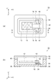
図1は、本発明の各実施形態に係る素子折り取り装置を用いて折り取った後の素子を搭載した振動子の概略図であり、図1(a)は平面図、図1(b)は図1(a)のA−A線断面図である。なお、図1(a)において、振動子10の内部の構成を説明する便宜上、リッド32を取り外した状態を図示している。
FIG. 1 is a schematic view of a vibrator on which an element is mounted after being folded using an element folding apparatus according to each embodiment of the present invention. FIG. 1 (a) is a plan view and FIG. 1 (b). FIG. 2 is a cross-sectional view taken along line AA in FIG. In FIG. 1A, for convenience of explaining the internal configuration of the
図1に示す振動子10は、本発明の各実施形態に係る素子折り取り装置により折り取られた素子12と、素子12を搭載するベース30と、素子12を気密封止するためのリッド32と、を含み構成されている。
ベース30とリッド32とは、素子12が実装されているキャビティ部を気密封止するために、低融点ガラスなどの接合部材40により接合されている。
A
The
素子12は、X軸方向を長辺方向とする略矩形形状であり、主面の表裏に励振電極14と、リード電極16と、パッド電極18とが形成されている。励振電極14は素子12のほぼ中央に、パッド電極18は素子12の端部に配置されており、励振電極14とパッド電極18とはリード電極16により電気的に接続されている。また、パッド電極18は、例えば、金属あるいは半田などからなるバンプや導電性接着剤などの接合部材42により、ベース30のキャビティ内に設けられた接続電極34に接合されている。なお、接続電極34はベース30の内部に設けられた貫通電極(図示せず)などを介して、外部端子36と電気的に接続されている。
The
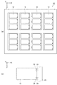
図2は、図1の振動子10に用いられる素子12が複数形成されたウェハー20の概略図であり、図2(a)はウェハー20の平面図、図2(b)は図2(a)の素子12とフレーム部22との支持部分の拡大図である。なお、素子12の励振電極14、リード電極16およびパッド電極18は図示を省略している。
2 is a schematic view of a
図2(a)に示すように、ウェハー20にはマトリックス状に配列された複数の素子12が形成されている。また、図2(b)に示すように、ウェハー20はフレーム部22を有し、このフレーム部22に支持部24を介して素子12が支持されている。支持部24は素子12と連結する側に、素子12を折り取りし易くするためのくびれ部26を有し、強度の弱くなったこのくびれ部26においてウェハー20のフレーム部22から素子12を分離することができる。なお、素子の長辺方向に沿った長さとは、支持部24と、支持部24の反対側にある自由端部とを結ぶ方向、即ちX軸方向の長さである。また、本実施形態では、1個の素子12に対して2本の支持部24で支持しているが、支持部24は1本以上であれば何本でも構わない。
As shown in FIG. 2A, the
<第1の実施形態>
図3は、本発明の第1の実施形態に係る素子折り取り装置を示す概略斜視図である。また、図4は、本発明の第1の実施形態に係る素子折り取り装置の素子折り取り部の拡大概略図であり、図4(a)は平面図、図4(b)は図4(a)のB−B線断面図である。
以下、ウェハー20から複数の素子12を折り取るための素子折り取り装置50についての説明とともに、この素子折り取り装置50を用いた素子の折り取り方法を説明する。
<First Embodiment>
FIG. 3 is a schematic perspective view showing the element breaker according to the first embodiment of the present invention. FIG. 4 is an enlarged schematic view of the element folding part of the element folding apparatus according to the first embodiment of the present invention, FIG. 4 (a) is a plan view, and FIG. 4 (b) is FIG. It is BB sectional drawing of a).
Hereinafter, the
本発明の第1の実施形態に係る素子折り取り装置50は、図3に示すように、ウェハー搭載部を有するウェハー搭載マスク70と、ウェハー20を押さえ込むように固定するウェハー押さえ部を有するウェハー押さえマスク60と、ウェハー搭載マスク70側からウェハー20に形成された素子12を吸引するための吸引手段と、を備えている。なお、吸引手段とは、吸引ボックス110の上部に設置された吸引プレート100の吸引口から吸引ボックス110に設けられた通気管112に接続した真空発生装置(図示せず)を駆動し、ウェハー搭載マスク70側の気圧を低くすることである。
As shown in FIG. 3, the
また、図4に示すように、ウェハー押さえマスク60に設けられた第2の開口部62と、ウェハー搭載マスク70に設けられた第1の開口部72と、素子収容トレー80に設けられた収容部82とはウェハー20に形成された複数の素子12にそれぞれ対向する位置に形成されている。更に、素子収容トレー80の収容部82に設けられた吸引口である吸引孔84と、吸引プレート100に設けられた吸引口である吸引孔102とはウェハー20に形成された複数の素子12にそれぞれ対向する位置で、且つ、素子12の外縁の内側に形成されている。
Further, as shown in FIG. 4, the
本発明の第1の実施形態に係る素子の折り取り方法は、先ず、複数の素子12を支持しているウェハー20と、ウェハー搭載マスク70とウェハー押さえマスク60とを備えた素子折り取り装置50を準備する。次に、位置決め用のピン(図示せず)とマスクを押さえるためのマグネット(図示せず)とを有するベースプレート90の上に素子収容トレー80を配置する。その後、素子収容トレー80の上にウェハー搭載マスク70、ウェハー20、ウェハー押さえマスク60の順に重ねて配置する。ここで、第1の開口部72、第2の開口部62、収容部82および吸引孔84の位置は、ウェハー押さえマスク60、ウェハー搭載マスク70および素子収容トレー80に設けられた位置決め用の孔(図示せず)をベースプレート90に設けられた位置決め用のピンに挿入することで、ウェハー20に形成された複数の素子12にそれぞれ対向する位置に合わせることができる。従って、ウェハー押さえマスク60と、ウェハー20と、ウェハー搭載マスク70とを積層する方向の平面視で、ウェハー押さえマスク60の第2の開口部62と、素子12と、ウェハー搭載マスク70の第1の開口部72とは重なるように配置される。
In the element folding method according to the first embodiment of the present invention, first, an
次に、ウェハー20を配置したベースプレート90を吸引ボックス110の上部に設置された吸引プレート100に重ねるように設置する。ここで、素子収容トレー80に設けられた吸引孔84と、吸引プレート100に設けられた吸引孔102とが重なり合うように配置する。次に、吸引ボックス110に設けられた通気管112に接続した真空ポンプなどの真空発生装置を駆動し素子12を吸引することで、ウェハー搭載マスク70の第1の開口部72側の気圧が低くなり素子12がウェハー搭載マスク70側に曲げられて折れる。よって、ウェハー20のフレーム部22に支持された複数の素子12を一括して折り取ることができる。その後、素子収容トレー80の収容部82に個片化して収容された素子12は、次工程であるパッケージへのマウント工程へ移される。
Next, the
次に、ウェハー押さえマスク60の第2の開口部62とウェハー搭載マスク70の第1の開口部72の位置関係について説明する。
図5は、本発明の第1の実施形態に係る素子折り取り装置の素子折り取り部の拡大概略図であり、図5(a)は平面図、図5(b)は図5(a)のC−C線断面図である。ここで、第1の開口部72の素子の長辺方向に沿った長さL1と第2の開口部62の素子の長辺方向に沿った長さL2とは、素子12の長さLXと同様に、X軸方向の長さのことである。
Next, the positional relationship between the
FIG. 5 is an enlarged schematic view of an element folding part of the element folding apparatus according to the first embodiment of the present invention, FIG. 5 (a) is a plan view, and FIG. 5 (b) is FIG. 5 (a). It is a CC sectional view taken on the line. Here, the length L1 along the long side direction of the element of the
図5に示すように、ウェハー搭載マスク70の第1の開口部72の長さL1(X軸方向の長さ)は、素子12の長さLX(X軸方向の長さ)より長い。これは折り取った素子12が確実に素子収容トレー80の収容部82に収まるようにするためである。また、ウェハー押さえマスク60の第2の開口部62の長さL2(X軸方向の長さ)は、素子12の長さLXより短く、ウェハー搭載マスク70の第1の開口部72の長さL1の1/2以上3/4以下の範囲内である。
As shown in FIG. 5, the length L1 (length in the X-axis direction) of the
これは、ウェハー押さえマスク60の第2の開口部62の長さL2が1/2より短い場合には、ウェハー押さえマスク60の第2の開口部62の面積が小さいため、ウェハー搭載マスク70側から吸引した際に、ウェハー押さえマスク60側とウェハー搭載マスク70側との気圧差が小さくなり、素子12を吸引する力が低下するため、折り取り難くなる。また、ウェハー押さえマスク60の第2の開口部62の長さL2が3/4より長い場合には、ウェハー押さえマスク60の第2の開口部62が素子12の端部より長くなり、素子12の端部との開放部が広がる。そのため、ウェハー押さえマスク60側からウェハー搭載マスク70側へ流出する空気が多くなり、ウェハー押さえマスク60側とウェハー搭載マスク70側との気圧差が小さくなることで、素子12を吸引する力が低下して折り取り難くなる。
This is because, when the length L2 of the
従って、ウェハー押さえマスク60の第2の開口部62の長さL2(X軸方向の長さ)は、素子12の長さLXより短く、ウェハー搭載マスク70の第1の開口部72の長さL1の1/2以上3/4以下の範囲内とすることで、ウェハー押さえマスク60側とウェハー搭載マスク70側との気圧差が小さくなることで生じる素子12が折り取り難くなる虞を低減することができる。
Therefore, the length L2 (the length in the X-axis direction) of the
更に、ウェハー押さえマスク60の第2の開口部62の長さL2の中心線C2は、ウェハー搭載マスク70の第1の開口部72の長さL1の中心線C1より、素子12と連結されたフレーム部22と反対側の素子12の端部方向(−X軸方向)にずらして設けられている。これはウェハー押さえマスク60の第2の開口部62が素子12の端部側にあることで、ウェハー搭載マスク70側からの吸引によって生じる吸引力を素子12の端部に集中させ、素子12の端部の変位量をより大きくし、折れ易くするためである。
Further, the center line C2 of the length L2 of the
このような第1の実施形態に係る素子の折り取り方法および素子折り取り装置50により、ウェハー搭載マスク70側から素子12を吸引することで、ウェハー20から複数の素子12を一括して折り取ることができ、従来の方法による素子12を傷つけることによる特性劣化を低減することができるという効果がある。
With the element folding method and the
<第2の実施形態>
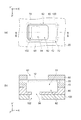
図6は、本発明の第2の実施形態に係る素子折り取り装置の素子折り取り部の拡大概略図であり、図6(a)は平面図、図6(b)は図6(a)のD−D線断面図である。
以下、第2の実施形態について、前述した第1の実施形態との相違点を中心に説明し、同様の事項については、その説明を省略する。
<Second Embodiment>
FIG. 6 is an enlarged schematic view of an element folding part of an element folding apparatus according to a second embodiment of the present invention, FIG. 6 (a) is a plan view, and FIG. 6 (b) is FIG. 6 (a). It is the DD sectional view taken on the line.
Hereinafter, the second embodiment will be described with a focus on differences from the first embodiment described above, and description of similar matters will be omitted.
図6に示すように、第2の実施形態に係るウェハー押さえマスク60aは、第1の実施形態に係るウェハー押さえマスク60と比較すると、素子12が配置されている側に突起部64が設けられている点が異なっている。ウェハー押さえマスク60aの突起部64は素子12に重なるように配置され、突起部64の高さH1(Y’軸方向の長さ)は0.03mm以上0.18mm以下の範囲内である。また、ウェハー押さえマスク60aの開口部の長さL3(X軸方向の長さ)はウェハー搭載マスク70の第1の開口部72の長さL1に対し1/8以上1/2以下の範囲内である。更に、ウェハー押さえマスク60aの第2の開口部62aの長さL3の中心線C3は、ウェハー搭載マスク70の第1の開口部72の長さL1の中心線C1より、素子12と連結されたフレーム部22と反対側の素子12の端部方向(−X軸方向)にずらして設けられている。
As shown in FIG. 6, the
ウェハー押さえマスク60aの突起部64が素子12と接する側に設けられ、素子12に重なるように配置されていることで、ウェハー20を押さえた際に、突起部64が素子12をウェハー搭載マスク70側へ押し込むためより折れ易くなるという効果がある。また、突起部64の高さH1を0.03mm以上0.18mm以下の範囲内とすることで、0.03mmより低い場合に生じる素子12を押し込む変位量が小さくなることで折り取り難くなる虞を低減し、0.18mmより高い場合にはより折り取りがし易くなるが素子12に傷を付け特性劣化を生じる虞を低減することができるという効果がある。
The
更に、ウェハー押さえマスク60aの第2の開口部62aの長さL3をウェハー搭載マスク70の第1の開口部72の長さL1に対し1/8以上1/2以下の範囲内とすることで、1/8より短い場合にウェハー押さえマスク60a側とウェハー搭載マスク70側との気圧差が小さくなることで生じる吸引力の低下による折り取り難くなる虞を低減できる。また、1/2より長い場合にはウェハー押さえマスク60の第2の開口部62aが素子12の先端部より長くなり、素子12の先端部との開放部が広がるので、ウェハー押さえマスク60a側からウェハー搭載マスク70側へ流出する空気が多くなり、ウェハー押さえマスク60a側とウェハー搭載マスク70側との気圧差が小さくなり、素子12を吸引する力が低下するため、折り取り難くなる虞を低減することができるという効果がある。
Further, the length L3 of the
また、第2の開口部62aの長さL3の中心線C3が第1の開口部72の長さL1の中心線C1より、素子12の端部方向(−X軸方向)にずらして設けられていることで、フレーム部22と連結されてない方向の素子12の端部を吸引することができるため、吸引による応力が増大し折り取りがし易くなるという効果がある。
Further, the center line C3 having the length L3 of the
<第3の実施形態>
図7は、本発明の第3の実施形態に係る素子の折り取り方法および素子折り取り装置を示す概略図である。
以下、素子折り取り装置50aの説明とともに、この素子折り取り装置50aを用いた折り取り方法を説明する。
また、第3の実施形態について、前述した第1の実施形態との相違点を中心に説明し、同様の事項については、その説明を省略する。
<Third Embodiment>
FIG. 7 is a schematic diagram showing an element folding method and element folding apparatus according to the third embodiment of the present invention.
Hereinafter, along with the description of the
In addition, the third embodiment will be described with a focus on differences from the first embodiment described above, and description of similar matters will be omitted.
図7に示すように、第3の実施形態に係る素子折り取り装置50aは、第1の実施形態に係る素子折り取り装置50と比較すると、アシストローラー120が設けられている点が異なっている。アシストローラー120により、吸引プレート100に設けられた吸引孔102から素子12を吸引している時に、ウェハー押さえマスク60の上をローリングすることで、吸引だけでは折り取れない素子12を折り取ることができるという効果がある。
As shown in FIG. 7, the
<第4の実施形態>
図8は、本発明の第4の実施形態に係る素子の折り取り方法および素子折り取り装置を示す概略図である。また、図9は、本発明の第4の実施形態に係る素子折り取り装置の素子折り取り部の拡大断面図である。
以下、素子折り取り装置50bの説明とともに、この素子折り取り装置50bを用いた折り取り方法を説明する。
また、第4の実施形態について、前述した第1の実施形態との相違点を中心に説明し、同様の事項については、その説明を省略する。
<Fourth Embodiment>
FIG. 8 is a schematic view showing an element folding method and element folding apparatus according to the fourth embodiment of the present invention. FIG. 9 is an enlarged cross-sectional view of an element folding part of an element folding apparatus according to the fourth embodiment of the present invention.
Hereinafter, along with the description of the
Further, the fourth embodiment will be described with a focus on the differences from the first embodiment described above, and the description of the same matters will be omitted.
図8に示すように、第4の実施形態に係る素子折り取り装置50bは、第1の実施形態に係る素子折り取り装置50と比較すると、アシストマスク130が設けられている点が異なっている。また、図9に示すように、アシストマスク130はウェハー押さえマスク60の第2の開口部62に収まる大きさの突起部134と開口部132を有している。なお、アシストマスク130の突起部134の高さH2(Y’軸方向の長さ)はウェハー押さえマスク60の板厚に0.03mm以上0.18mm以下の範囲内を加えた高さである。また、アシストマスク130の開口部の長さL4(X軸方向の長さ)はウェハー搭載マスク70の第1の開口部72の長さL1に対し1/8以上1/2以下の範囲内である。また、アシストマスク130の開口部の長さL4の中心線C4は、ウェハー搭載マスク70の第1の開口部72の長さL1の中心線C1より、素子12と連結されたフレーム部22と反対側の素子12の端部方向(−X軸方向)にずらして設けられている。
As shown in FIG. 8, the
アシストマスク130の突起部134の高さH2をウェハー押さえマスク60の板厚T1(Y’軸方向の長さ)に0.03mm以上0.18mm以下の範囲内を加えた高さとすることで、ウェハー20をウェハー押さえマスク60で押さえた状態で、突起部134が素子12をウェハー搭載マスク70側に押し込むことができるので、より確実に素子12を折り取ることができる。
By setting the height H2 of the
このような第4の実施形態に係る素子の折り取り方法および素子折り取り装置50bにより、素子12を吸引することで、ウェハー20から折り取られずに残っている素子12であっても、アシストマスク130の突起部134により素子12を押し込むことができるため、確実に折り取ることができるという効果がある。
Even if the
<第5の実施形態>
図10は、本発明の第5の実施形態に係る素子の折り取り方法および素子折り取り装置を示す概略図である。
以下、素子折り取り装置50cの説明とともに、この素子折り取り装置50cを用いた折り取り方法を説明する。
また、第5の実施形態について、前述した第4の実施形態との相違点を中心に説明し、同様の事項については、その説明を省略する。
<Fifth Embodiment>
FIG. 10 is a schematic view showing an element folding method and element folding apparatus according to the fifth embodiment of the present invention.
Hereinafter, along with the description of the
Further, the fifth embodiment will be described focusing on the differences from the above-described fourth embodiment, and description of similar matters will be omitted.
図10に示すように、第5の実施形態に係る素子折り取り装置50cは、第4の実施形態に係る素子折り取り装置50bと比較すると、アシストローラー120が設けられている点が異なっている。アシストローラー120により、吸引プレート100に設けられた吸引孔102から素子12を吸引している時に、アシストマスク130の上をローリングすることで、吸引だけでは折り取れない素子12を折り取ることができるという効果がある。
As shown in FIG. 10, the
10…振動子、12…素子、14…励振電極、16…リード電極、18…パッド電極、20…ウェハー、22…フレーム部、24…支持部、26…くびれ部、30…ベース、32…リッド、34…接続電極、36…外部端子、40…接合部材、42…接合部材、50…素子折り取り装置、60…ウェハー押さえマスク、62…第2の開口部、64…突起部、70…ウェハー搭載マスク、72…第1の開口部、80…素子収容トレー、82…収容部、84…吸引孔、90…ベースプレート、100…吸引プレート、102…吸引孔、110…吸引ボックス、112…通気管、120…アシストローラー、130…アシストマスク、132…開口部、134…突起部。
DESCRIPTION OF
Claims (14)
前記ウェハー載置部と前記ウェハーと前記ウェハー押さえ部とを平面視で、前記素子が前記ウェハー載置部の前記第1の開口部の外縁の内側に位置し、且つ、前記ウェハー載置部の前記第1の開口部と前記ウェハー押さえ部の前記第2の開口部との中心がずれるような位置に、前記ウェハー載置部と前記ウェハーと前記ウェハー押さえ部とを積層し配置する工程と、
前記素子に対して前記ウェハー押さえ部側よりも前記ウェハー載置部側の気圧を低くして、前記ウェハーから前記素子を折り取る工程と、
を含むことを特徴とする素子の折り取り方法。 A wafer supporting the element, a wafer mounting portion having a first opening, and a length along the long side direction of the element from the first opening of the wafer mounting portion. A step of preparing an element folding device including a wafer pressing portion having a short second opening;
The wafer mounting portion, the wafer, and the wafer pressing portion are viewed in plan, the element is located inside the outer edge of the first opening of the wafer mounting portion, and the wafer mounting portion Laminating and arranging the wafer mounting portion, the wafer, and the wafer pressing portion at a position where the center of the first opening and the second opening of the wafer pressing portion is deviated,
Lowering the pressure on the wafer mounting part side relative to the wafer holding part side with respect to the element, and folding the element from the wafer;
An element folding method comprising:
前記ウェハー載置部の前記第1の開口部よりも前記素子の長辺方向に沿った長さが短い第2の開口部を有し、前記ウェハー載置部とともに前記ウェハーを挟むように固定するためのウェハー押さえ部と、
前記ウェハー載置部側に前記素子を吸引するための吸引手段と、
を備えていることを特徴とする素子折り取り装置。 A wafer mounting portion for mounting a wafer having a first opening and supporting the element;
The wafer mounting portion has a second opening portion whose length along the long side direction of the element is shorter than that of the first opening portion, and is fixed so as to sandwich the wafer together with the wafer mounting portion. A wafer holding part for
A suction means for sucking the element toward the wafer mounting portion;
An element folding device comprising:
Priority Applications (1)
| Application Number | Priority Date | Filing Date | Title |
|---|---|---|---|
| JP2013027613A JP6163779B2 (en) | 2013-02-15 | 2013-02-15 | Element folding method and element folding apparatus |
Applications Claiming Priority (1)
| Application Number | Priority Date | Filing Date | Title |
|---|---|---|---|
| JP2013027613A JP6163779B2 (en) | 2013-02-15 | 2013-02-15 | Element folding method and element folding apparatus |
Publications (2)
| Publication Number | Publication Date |
|---|---|
| JP2014158148A JP2014158148A (en) | 2014-08-28 |
| JP6163779B2 true JP6163779B2 (en) | 2017-07-19 |
Family
ID=51578779
Family Applications (1)
| Application Number | Title | Priority Date | Filing Date |
|---|---|---|---|
| JP2013027613A Expired - Fee Related JP6163779B2 (en) | 2013-02-15 | 2013-02-15 | Element folding method and element folding apparatus |
Country Status (1)
| Country | Link |
|---|---|
| JP (1) | JP6163779B2 (en) |
Families Citing this family (1)
| Publication number | Priority date | Publication date | Assignee | Title |
|---|---|---|---|---|
| JP6385759B2 (en) * | 2014-08-29 | 2018-09-05 | 京セラ株式会社 | Piezoelectric piece breaker and method for manufacturing piezoelectric piece |
Family Cites Families (3)
| Publication number | Priority date | Publication date | Assignee | Title |
|---|---|---|---|---|
| JP4891001B2 (en) * | 2006-08-29 | 2012-03-07 | 日本電波工業株式会社 | Method for manufacturing vibrating piece, method for manufacturing crystal vibrating device, crystal vibrating piece and crystal vibrating device |
| JP4949937B2 (en) * | 2007-06-08 | 2012-06-13 | パイオニア株式会社 | Component division take-out apparatus and component division take-out method |
| JP5251369B2 (en) * | 2008-09-03 | 2013-07-31 | セイコーエプソン株式会社 | Method for manufacturing piezoelectric vibrating piece |
-
2013
- 2013-02-15 JP JP2013027613A patent/JP6163779B2/en not_active Expired - Fee Related
Also Published As
| Publication number | Publication date |
|---|---|
| JP2014158148A (en) | 2014-08-28 |
Similar Documents
| Publication | Publication Date | Title |
|---|---|---|
| US7902731B2 (en) | Piezoelectric resonator device and method for manufacturing the same | |
| JP2008004936A (en) | Device for detaching semiconductor chip with pair of ejector and method for detaching semiconductor chip using the same | |
| US10673408B2 (en) | Resonance device | |
| CN101199114A (en) | Piezoelectric vibration piece and piezoelectric vibration device | |
| JP4007143B2 (en) | Electronic component, electronic component manufacturing method and manufacturing apparatus | |
| JP6163779B2 (en) | Element folding method and element folding apparatus | |
| JP6301565B1 (en) | Method and apparatus for separating a microchip from a wafer and mounting the microchip on a substrate | |
| JP2002325024A (en) | Electronic component and method for forming substrate electrode thereof | |
| JP5376490B2 (en) | Manufacturing method of electronic component package | |
| EP3993024A1 (en) | Electronic component housing package, electronic device, and electronic module | |
| TWI442611B (en) | Method for manufacturing oscillator device and oscillator device | |
| JP2010021519A (en) | Flat frame member for lead frame, lead frame and method of manufacturing same, package body, package, semiconductor device, and microphone package | |
| JP5187299B2 (en) | Manufacturing method of semiconductor device | |
| JP4144036B2 (en) | Electronic component package and piezoelectric vibration device using the electronic component package | |
| JP2014150363A (en) | Piezoelectric device and method for manufacturing the same | |
| JP5631548B2 (en) | Electronic component package | |
| JP5632031B2 (en) | Manufacturing method of electronic component package | |
| JP5246691B2 (en) | Electronic component package | |
| JP2010273006A (en) | Vibration device | |
| JP5376492B2 (en) | Electronic component package and method of manufacturing electronic component package | |
| JP2006156558A (en) | Multiple wiring board, package for storing electronic component, and electronic device | |
| US10447237B2 (en) | Piezoelectric blank, piezoelectric vibration element and piezoelectric vibration device | |
| KR20240034948A (en) | Micro Electro-Mechanical Systems package and method for manufacturing the same | |
| JP5184427B2 (en) | Electronic component package and method of manufacturing electronic component package | |
| JP6004957B2 (en) | Quartz crystal resonator and manufacturing method thereof |
Legal Events
| Date | Code | Title | Description |
|---|---|---|---|
| RD04 | Notification of resignation of power of attorney |
Free format text: JAPANESE INTERMEDIATE CODE: A7424 Effective date: 20150109 |
|
| A621 | Written request for application examination |
Free format text: JAPANESE INTERMEDIATE CODE: A621 Effective date: 20160107 |
|
| RD04 | Notification of resignation of power of attorney |
Free format text: JAPANESE INTERMEDIATE CODE: A7424 Effective date: 20160610 |
|
| RD03 | Notification of appointment of power of attorney |
Free format text: JAPANESE INTERMEDIATE CODE: A7423 Effective date: 20160624 |
|
| A977 | Report on retrieval |
Free format text: JAPANESE INTERMEDIATE CODE: A971007 Effective date: 20160920 |
|
| A131 | Notification of reasons for refusal |
Free format text: JAPANESE INTERMEDIATE CODE: A131 Effective date: 20161101 |
|
| A521 | Request for written amendment filed |
Free format text: JAPANESE INTERMEDIATE CODE: A523 Effective date: 20161227 |
|
| TRDD | Decision of grant or rejection written | ||
| A01 | Written decision to grant a patent or to grant a registration (utility model) |
Free format text: JAPANESE INTERMEDIATE CODE: A01 Effective date: 20170523 |
|
| A61 | First payment of annual fees (during grant procedure) |
Free format text: JAPANESE INTERMEDIATE CODE: A61 Effective date: 20170605 |
|
| R150 | Certificate of patent or registration of utility model |
Ref document number: 6163779 Country of ref document: JP Free format text: JAPANESE INTERMEDIATE CODE: R150 |
|
| LAPS | Cancellation because of no payment of annual fees |