JP6163460B2 - Accompanying work system - Google Patents

Accompanying work system Download PDF

Info

Publication number
JP6163460B2
JP6163460B2 JP2014135416A JP2014135416A JP6163460B2 JP 6163460 B2 JP6163460 B2 JP 6163460B2 JP 2014135416 A JP2014135416 A JP 2014135416A JP 2014135416 A JP2014135416 A JP 2014135416A JP 6163460 B2 JP6163460 B2 JP 6163460B2
Authority
JP
Japan
Prior art keywords
work vehicle
traveling
accompanying
vehicle
control device
Prior art date
Legal status (The legal status is an assumption and is not a legal conclusion. Google has not performed a legal analysis and makes no representation as to the accuracy of the status listed.)
Active
Application number
JP2014135416A
Other languages
Japanese (ja)
Other versions
JP2015186473A (en
Inventor
敏史 平松
敏史 平松
中川 渉
渉 中川
青木 英明
英明 青木
Current Assignee (The listed assignees may be inaccurate. Google has not performed a legal analysis and makes no representation or warranty as to the accuracy of the list.)
Yanmar Co Ltd
Original Assignee
Yanmar Co Ltd
Priority date (The priority date is an assumption and is not a legal conclusion. Google has not performed a legal analysis and makes no representation as to the accuracy of the date listed.)
Filing date
Publication date
Application filed by Yanmar Co Ltd filed Critical Yanmar Co Ltd
Priority to JP2014135416A priority Critical patent/JP6163460B2/en
Publication of JP2015186473A publication Critical patent/JP2015186473A/en
Application granted granted Critical
Publication of JP6163460B2 publication Critical patent/JP6163460B2/en
Active legal-status Critical Current
Anticipated expiration legal-status Critical

Links

Images

Description

本発明は、自律走行する自律走行作業車両と、この自律走行作業車両に随伴して併走走行する随伴走行作業車両とにより作業を行う場合において、枕地等で旋回するときに自律走行作業車両と随伴走行作業車両が併走走行を維持する随伴作業システムに関する。 The present invention relates to an autonomous traveling work vehicle when turning on a headland or the like when working with an autonomous traveling working vehicle that travels autonomously and an accompanying traveling working vehicle that travels along with the autonomous traveling work vehicle. The present invention relates to an accompanying work system in which an accompanying traveling work vehicle maintains parallel traveling.

従来、マスター車両がオペレータにより運転操作され、スレーブ車両が無人車両として、マスター車両及びスレーブ車両はそれぞれ制御装置を備え、無線により車両間の連絡を可能とし、スレーブ車両はマスター車両に対して平行運転が可能なプログラムが備えられている。そして、マスター車両とスレーブ車両には距離測定装置を備え、マスター車両とスレーブ車両の間の距離が所定距離となるように調整される技術が公知となっている(例えば、特許文献1参照)。   Conventionally, the master vehicle is operated by an operator, the slave vehicle is an unmanned vehicle, the master vehicle and the slave vehicle are each equipped with a control device, and communication between the vehicles is possible by radio, and the slave vehicle is operated in parallel to the master vehicle. A program that can do this is provided. And the technique which adjusts so that the distance between a master vehicle and a slave vehicle may be provided with a distance measuring apparatus in a master vehicle and a slave vehicle may become well-known (for example, refer patent document 1).

特表2001−507843号公報JP-T-2001-507843

前記従来技術において、マスター車両とスレーブ車両が圃場端に至ると、スレーブ車両は手動操作に切り替えて、オペレータがスレーブ車両を運転して次の作業路に移動するようにしていた。従って、圃場端に至る毎に両車両を停止させて、乗り換えて一台ずつ旋回させる必要があった。そのため作業効率が悪くなっていた。   In the prior art, when the master vehicle and the slave vehicle reach the end of the field, the slave vehicle is switched to manual operation, and the operator drives the slave vehicle to move to the next work path. Therefore, it was necessary to stop both vehicles each time they reached the end of the field, change trains and turn them one by one. As a result, work efficiency has deteriorated.

本発明は、以上の如き状況に鑑みてなされたものであり、自律走行する自律走行作業車両が圃場端に至ると枕地旋回し、旋回終了後一定距離直進させて一旦停止させ、その後、遠隔操作装置から再開始信号に基づいて、自律走行作業車両と随伴走行作業車両との位置関係の如何を問わず、自律走行作業車両の自律走行を再開させる随伴作業システムを提供することを課題とする。 The present invention has been made in consideration of the above-mentioned circumstances, autonomous work vehicle to autonomous reaches the to headland turning in the field end, once stopped by turning after the end by a predetermined distance straight, after them, It is an object to provide an accompanying work system for resuming autonomous traveling of an autonomous traveling work vehicle based on a restart signal from a remote control device, regardless of the positional relationship between the autonomous traveling working vehicle and the accompanying traveling work vehicle. To do.

本発明の解決しようとする課題は以上の如くであり、次にこの課題を解決するための手段を説明する。
請求項1においては、衛星測位システムを利用して自律走行作業車両の位置を測位する位置算出手段と、操舵装置を作動させる操舵アクチュエータと、エンジン回転制御手段と、変速手段と、各部を制御して設定走行経路に沿って前記自律走行作業車両を自律走行させる制御装置と、前記自律走行作業車両の後方を走行する随伴走行作業車両に搭載可能であると共に前記制御装置に再開始信号を送信可能な遠隔操作装置と、を備え、前記制御装置は、前記自律走行作業車両が設定走行経路に沿って枕地旋回させた後に自律走行作業車両を一定距離直進させて一旦停止し、前記一旦停止させた後に前記遠隔操作装置から再開始信号を受信したときは、前記自律走行作業車両と前記随伴走行作業車両との位置関係の如何を問わず、前記自律走行作業車両の自律走行を再開させることが可能である随伴作業システムである。
The problem to be solved by the present invention is as described above. Next, means for solving the problem will be described.
According to the first aspect of the present invention, the position calculating means for positioning the position of the autonomous traveling work vehicle using the satellite positioning system, the steering actuator for operating the steering device, the engine rotation control means, the speed change means, and each part are controlled. Can be mounted on a control device that autonomously travels the autonomous traveling work vehicle along the set traveling route and an accompanying traveling work vehicle that travels behind the autonomous traveling work vehicle and can transmit a restart signal to the control device Remote control device, and after the autonomous traveling work vehicle turns the headland along the set traveling route, the control device causes the autonomous traveling work vehicle to go straight ahead for a certain distance, and then temporarily stops. When a restart signal is received from the remote control device after that, regardless of the positional relationship between the autonomous traveling work vehicle and the accompanying traveling working vehicle, the autonomous traveling operation Is associated working system it is possible to resume the autonomous vehicle.

請求項2においては、前記制御装置は、前記遠隔操作装置から再開始信号を受信する前に、前記遠隔操作装置から随伴走行作業車両の枕地旋回終了信号を受信した場合は、前記自律走行作業車両の自律走行を再開させるものである。 According to a second aspect of the present invention, when the control device receives a headland turn end signal of an accompanying traveling work vehicle from the remote operation device before receiving a restart signal from the remote operation device, the autonomous traveling work This is to restart the autonomous driving of the vehicle .

請求項3においては、前記制御装置は、前記遠隔操作装置から再開始信号を受信する前に、前記遠隔操作装置から取得した前記随伴走行作業車両の走行状態を示す信号に基づいて随伴走行作業車両の枕地旋回が終了したと判断した場合は、前記自律走行作業車両の自律走行を再開させるものである。 In Claim 3, the said control apparatus is based on the signal which shows the traveling state of the said accompanying traveling work vehicle acquired from the said remote operation apparatus before receiving the restart signal from the said remote operating apparatus. If it is determined that the headland turn of the vehicle has ended, the autonomous traveling of the autonomous traveling work vehicle is resumed .

請求項4においては、前記随伴走行作業車両の走行状態を示す信号は、前記随伴走行作業車両が備える操向センサまたは方位センサまたは車速センサの検出値を示す信号である。 According to a fourth aspect of the present invention, the signal indicating the traveling state of the accompanying traveling work vehicle is a signal indicating a detected value of a steering sensor, a direction sensor, or a vehicle speed sensor included in the accompanying traveling working vehicle.

請求項5においては、前記随伴走行作業車両の走行状態を示す情報は、前記随伴走行作業車両が備えるカメラの映像情報を示す信号である。 According to a fifth aspect of the present invention, the information indicating the traveling state of the accompanying traveling work vehicle is a signal indicating video information of a camera included in the accompanying traveling working vehicle.

請求項6においては、前記随伴走行作業車両の走行状態を示す情報は、前記随伴走行作業車両が備える作業機の昇降を検知する作業機昇降検知手段から出力される上昇信号及び下降信号である。 According to a sixth aspect of the present invention, the information indicating the traveling state of the accompanying traveling work vehicle is an ascending signal and a descending signal output from a work implement raising / lowering detecting unit that detects raising / lowering of a working implement included in the accompanying traveling work vehicle.

本発明によれば、自律走行作業車両が設定走行経路に沿って枕地旋回させた後に自律走行作業車両を一定距離直進させて一旦停止し、前記一旦停止させた後に遠隔操作装置から再開始信号を受信したときに、自律走行作業車両と随伴走行作業車両との位置関係の如何を問わず、自律走行作業車両の自律走行を再開させることが可能であるので、オペレータは自律走行作業車両に乗り換えて、自律走行作業車両を旋回操作する必要がなく、枕地旋回後、遠隔操作装置を介して自律走行を再開させ、効率よく作業ができ、自律走行作業車両と随伴走行作業車両がバラバラに作業することもない。 According to the present invention, after the autonomous traveling work vehicle turns the headland along the set traveling route, the autonomous traveling work vehicle goes straight for a certain distance and stops temporarily. Since the autonomous traveling work vehicle can be resumed autonomously regardless of the positional relationship between the autonomous traveling working vehicle and the accompanying traveling working vehicle , the operator switches to the autonomous traveling working vehicle. Therefore, it is not necessary to turn the autonomous traveling work vehicle, and after turning the headland, the autonomous traveling can be resumed via the remote control device, so that the work can be performed efficiently. The autonomous traveling work vehicle and the accompanying traveling working vehicle work separately. I don't have to.

自律走行作業車両とGPS衛星と基準局を示す概略側面図。The schematic side view which shows an autonomous traveling work vehicle, a GPS satellite, and a reference station. 制御ブロック図。Control block diagram. 枕地旋回制御を示すフローチャート図。The flowchart figure which shows headland turning control. 併走作業の圃場端前の状態を示す図。The figure which shows the state before the agricultural field end of parallel running. 併走作業の圃場端での旋回状態を示す図。The figure which shows the turning state in the agricultural field end of parallel running. 併走作業の圃場端での待機状態を示す図。The figure which shows the standby state in the agricultural field end of parallel operation. 前後一列作業の状態を示す図。The figure which shows the state of front-and-back one line work. 圃場端での旋回状態を示す図。The figure which shows the turning state in the field end.

無人で自動走行可能な自律走行作業車両1、及び、この自律走行作業車両1に随伴してオペレータが操向操作する有人の随伴走行作業車両100をトラクタとし、自律走行作業車両1及び随伴走行作業車両100には作業機としてロータリ耕耘装置がそれぞれ装着されている実施例について説明する。但し、作業車両はトラクタに限定するものではなく、コンバイン等でもよく、また、作業機はロータリ耕耘装置に限定するものではなく、畝立て機や草刈機やレーキや播種機や施肥機やワゴン等であってもよい。   The autonomous traveling work vehicle 1 capable of unmanned automatic traveling and the manned traveling traveling vehicle 100 operated by the operator accompanying the autonomous traveling working vehicle 1 as a tractor are used as the tractor. An embodiment will be described in which a rotary tiller is mounted as a work machine on the vehicle 100. However, the work vehicle is not limited to a tractor, and may be a combine. The work machine is not limited to a rotary tiller. A vertical machine, a mower, a rake, a seeder, a fertilizer, a wagon, etc. It may be.

図1、図2において、自律走行作業車両1となるトラクタの全体構成について説明する。ボンネット2内にエンジン3が内設され、該ボンネット2の後部のキャビン11内にダッシュボード14が設けられ、ダッシュボード14上に操向操作手段となるステアリングハンドル4が設けられている。該ステアリングハンドル4の回動により操舵装置を介して前輪9・9の向きが回動される。自律走行作業車両1の操舵方向は操向センサ20により検知される。操向センサ20はロータリエンコーダ等の角度センサからなり、前輪9の回動基部に配置される。但し、操向センサ20の検知構成は限定するものではなく操舵方向が認識されるものであればよく、ステアリングハンドル4の回動を検知したり、パワーステアリングの作動量を検知してもよい。操向センサ20により得られた検出値は制御装置30に入力される。制御装置30はCPU(中央演算処理装置)やRAMやROM等の記憶装置やインターフェース等を備え、記憶装置には自律走行作業車両1を動作させるためのプログラムやデータ等が記憶される。   1 and 2, an overall configuration of a tractor that becomes an autonomous traveling work vehicle 1 will be described. An engine 3 is installed in the hood 2, a dashboard 14 is provided in a cabin 11 at the rear of the hood 2, and a steering handle 4 serving as a steering operation means is provided on the dashboard 14. The steering wheel 4 is rotated to rotate the front wheels 9 and 9 through the steering device. The steering direction of the autonomous traveling work vehicle 1 is detected by the steering sensor 20. The steering sensor 20 is composed of an angle sensor such as a rotary encoder, and is disposed at the rotation base of the front wheel 9. However, the detection configuration of the steering sensor 20 is not limited as long as the steering direction is recognized, and the rotation of the steering handle 4 may be detected or the operation amount of the power steering may be detected. The detection value obtained by the steering sensor 20 is input to the control device 30. The control device 30 includes a CPU (Central Processing Unit), a storage device such as a RAM and a ROM, an interface, and the like, and the storage device stores programs, data, and the like for operating the autonomous traveling work vehicle 1.

前記ステアリングハンドル4の後方に運転席5が配設され、運転席5下方にミッションケース6が配置される。ミッションケース6の左右両側にリアアクスルケース8・8が連設され、該リアアクスルケース8・8には車軸を介して後輪10・10が支承される。エンジン3からの動力はミッションケース6内の変速装置(主変速装置や副変速装置)により変速されて、後輪10・10を駆動可能としている。変速装置は例えば油圧式無段変速装置で構成して、可変容量型の油圧ポンプの可動斜板をモータ等の変速手段44により作動させて変速可能としている。変速手段44は制御装置30と接続されている。後輪10の回転数は車速センサ27により検知され、走行速度として制御装置30に入力される。但し、車速の検知方法や車速センサ27の配置位置は限定するものではない。   A driver seat 5 is disposed behind the steering handle 4, and a mission case 6 is disposed below the driver seat 5. Rear axle cases 8 and 8 are connected to the left and right sides of the transmission case 6, and rear wheels 10 and 10 are supported on the rear axle cases 8 and 8 via axles. The power from the engine 3 is shifted by a transmission (a main transmission or an auxiliary transmission) in the mission case 6 so that the rear wheels 10 and 10 can be driven. The transmission is constituted by, for example, a hydraulic continuously variable transmission, and the movable swash plate of a variable displacement hydraulic pump is operated by a transmission means 44 such as a motor so that the transmission can be changed. The speed change means 44 is connected to the control device 30. The rotational speed of the rear wheel 10 is detected by the vehicle speed sensor 27 and is input to the control device 30 as the traveling speed. However, the vehicle speed detection method and the arrangement position of the vehicle speed sensor 27 are not limited.

ミッションケース6内にはPTOクラッチやPTO変速装置が収納され、PTOクラッチはPTO入切手段45により入り切りされ、PTO入切手段45は制御装置30と接続され、PTO軸への動力の断接を制御可能としている。   The transmission case 6 houses a PTO clutch and a PTO transmission. The PTO clutch is turned on and off by a PTO on / off means 45. The PTO on / off means 45 is connected to the control device 30 to connect and disconnect the power to the PTO shaft. It can be controlled.

前記エンジン3を支持するフロントフレーム13にはフロントアクスルケース7が支持され、該フロントアクスルケース7の両側に前輪9・9が支承され、前記ミッションケース6からの動力が前輪9・9に伝達可能に構成している。前記前輪9・9は操舵輪となっており、ステアリングハンドル4の回動操作により回動可能とするとともに、操舵装置の駆動手段となるパワステシリンダからなる操舵アクチュエータ40により前輪9・9が左右操舵回動可能となっている。操舵アクチュエータ40は制御装置30と接続され、自動走行手段により制御されて駆動される。   A front axle case 7 is supported on a front frame 13 that supports the engine 3, and front wheels 9 and 9 are supported on both sides of the front axle case 7, and power from the transmission case 6 can be transmitted to the front wheels 9 and 9. It is configured. The front wheels 9 and 9 are steered wheels, which can be turned by turning the steering handle 4, and the front wheels 9 and 9 are steered left and right by a steering actuator 40 comprising a power steering cylinder as a driving means of the steering device. It can be turned. The steering actuator 40 is connected to the control device 30 and is controlled and driven by automatic traveling means.

制御装置30にはエンジン回転制御手段となるエンジンコントローラ60が接続され、エンジンコントローラ60にはエンジン回転数センサ61や水温センサや油圧センサ等が接続され、エンジンの状態を検知できるようにしている。エンジンコントローラ60では設定回転数と実回転数から負荷を検出し、過負荷とならないように制御するとともに、後述する遠隔操作装置112にエンジン3の状態を送信してディスプレイ113で表示できるようにしている。   An engine controller 60 serving as engine rotation control means is connected to the control device 30, and an engine rotation speed sensor 61, a water temperature sensor, a hydraulic pressure sensor, and the like are connected to the engine controller 60 so that the state of the engine can be detected. The engine controller 60 detects the load from the set rotational speed and the actual rotational speed and controls it so as not to be overloaded, and transmits the state of the engine 3 to the remote operation device 112 described later so that it can be displayed on the display 113. Yes.

また、ステップ下方に配置した燃料タンク15には燃料の液面を検知するレベルセンサ29が配置されて制御装置30と接続され、自律走行作業車両1のダッシュボードに設ける表示手段49には燃料の残量を表示する燃料計が設けられ制御装置30と接続されている。そして、制御装置30から遠隔操作装置112に燃料残量に関する情報が送信されて、遠隔操作装置112のディスプレイ113に燃料残量と作業可能時間が表示される。   The fuel tank 15 disposed below the step is provided with a level sensor 29 for detecting the fuel level and is connected to the control device 30. The display means 49 provided on the dashboard of the autonomous traveling work vehicle 1 has a fuel supply. A fuel gauge for displaying the remaining amount is provided and connected to the control device 30. Then, information regarding the remaining amount of fuel is transmitted from the control device 30 to the remote operation device 112, and the remaining fuel amount and workable time are displayed on the display 113 of the remote operation device 112.

前記ダッシュボード14上にはエンジンの回転計や燃料計や油圧等や異常を示すモニタや設定値等を表示する表示手段49が配置されている。   On the dashboard 14, display means 49 for displaying an engine tachometer, a fuel gauge, a hydraulic pressure, etc., an abnormal monitor, a set value, and the like are arranged.

また、トラクタ機体後方に作業機装着装置23を介して作業機としてロータリ耕耘装置24が昇降自在に装設させて耕耘作業を行うように構成している。前記ミッションケース6上に昇降シリンダ26が設けられ、該昇降シリンダ26を伸縮させることにより、作業機装着装置23を構成する昇降アームを回動させてロータリ耕耘装置24を昇降できるようにしている。昇降シリンダ26は昇降アクチュエータ25の作動により伸縮され、昇降アクチュエータ25は制御装置30と接続されている。   Further, a rotary tiller 24 is installed as a work machine behind the tractor body via a work machine mounting device 23 so as to be able to move up and down to perform the tilling work. An elevating cylinder 26 is provided on the transmission case 6, and the elevating arm 26 constituting the work implement mounting device 23 is rotated by moving the elevating cylinder 26 to extend and lower the rotary tiller 24. The lift cylinder 26 is expanded and contracted by the operation of the lift actuator 25, and the lift actuator 25 is connected to the control device 30.

制御装置30には衛星測位システムを構成する移動通信機33が接続されている。移動通信機33には移動GPSアンテナ34とデータ受信アンテナ38が接続され、移動GPSアンテナ34とデータ受信アンテナ38は前記キャビン11上に設けられる。該移動通信機33には、位置算出手段を備えて緯度と経度を制御装置30に送信し、現在位置を把握できるようにしている。なお、GPS(米国)に加えて準天頂衛星( 日本) やグロナス衛星(ロシア)等の衛星測位システム(GNSS)を利用することで精度の高い測位ができるが、本実施形態ではGPSを用いて説明する。   A mobile communication device 33 constituting a satellite positioning system is connected to the control device 30. A mobile GPS antenna 34 and a data receiving antenna 38 are connected to the mobile communication device 33, and the mobile GPS antenna 34 and the data receiving antenna 38 are provided on the cabin 11. The mobile communicator 33 is provided with a position calculating means for transmitting latitude and longitude to the control device 30 so that the current position can be grasped. In addition to GPS (United States), high-precision positioning can be performed by using a satellite positioning system (GNSS) such as a quasi-zenith satellite (Japan) or a Glonus satellite (Russia). In this embodiment, GPS is used. explain.

自律走行作業車両1は、機体の姿勢変化情報を得るためにジャイロセンサ31、および進行方向を検知するために方位センサ32を具備し制御装置30と接続されている。但し、GPSの位置計測から進行方向を算出できるので、方位センサ32を省くことができる。ジャイロセンサ31は自律走行作業車両1の機体前後方向の傾斜(ピッチ)の角速度、機体左右方向の傾斜(ロール)の角速度、および旋回(ヨー)の角速度、を検出するものである。該三つの角速度を積分計算することにより、自律走行作業車両1の機体の前後方向および左右方向への傾斜角度、および旋回角度を求めることが可能である。ジャイロセンサ31の具体例としては、機械式ジャイロセンサ、光学式ジャイロセンサ、流体式ジャイロセンサ、振動式ジャイロセンサ等が挙げられる。ジャイロセンサ31は制御装置30に接続され、当該三つの角速度に係る情報を制御装置30に入力する。   The autonomous traveling work vehicle 1 includes a gyro sensor 31 for obtaining attitude change information of the airframe, and an orientation sensor 32 for detecting a traveling direction, and is connected to the control device 30. However, since the traveling direction can be calculated from the GPS position measurement, the direction sensor 32 can be omitted. The gyro sensor 31 detects an angular velocity of a tilt (pitch) in the longitudinal direction of the autonomous traveling work vehicle 1, an angular velocity of a tilt (roll) in the lateral direction of the aircraft, and an angular velocity of turning (yaw). By integrating and calculating the three angular velocities, it is possible to obtain the tilt angle in the front-rear direction and the left-right direction and the turning angle of the body of the autonomous traveling work vehicle 1. Specific examples of the gyro sensor 31 include a mechanical gyro sensor, an optical gyro sensor, a fluid gyro sensor, and a vibration gyro sensor. The gyro sensor 31 is connected to the control device 30 and inputs information relating to the three angular velocities to the control device 30.

方位センサ32は自律走行作業車両1の向き(進行方向)を検出するものである。方位センサ32の具体例としては磁気方位センサ等が挙げられる。方位センサ32は制御装置30に接続され、機体の向きに係る情報を制御装置30に入力する。   The direction sensor 32 detects the direction (traveling direction) of the autonomous traveling work vehicle 1. A specific example of the direction sensor 32 includes a magnetic direction sensor. The direction sensor 32 is connected to the control device 30 and inputs information related to the orientation of the aircraft to the control device 30.

こうして制御装置30は、上記ジャイロセンサ31、方位センサ32から取得した信号を姿勢・方位演算手段により演算し、自律走行作業車両1の姿勢(向き、機体前後方向及び機体左右方向の傾斜、旋回方向)を求める。   In this way, the control device 30 calculates the signals acquired from the gyro sensor 31 and the azimuth sensor 32 by the attitude / azimuth calculation means, and the attitude of the autonomous traveling work vehicle 1 (orientation, forward / backward direction of the body, left / right direction of the body, turning direction). )

次に、自律走行作業車両1の位置情報をGPS(グローバル・ポジショニング・システム)を用いて取得する方法について説明する。GPSは、元来航空機・船舶等の航法支援用として開発されたシステムであって、上空約二万キロメートルを周回する二十四個のGPS衛星(六軌道面に四個ずつ配置)、GPS衛星の追跡と管制を行う管制局、測位を行うための利用者の通信機で構成される。GPSを用いた測位方法としては、単独測位、相対測位、DGPS(ディファレンシャルGPS)測位、RTK−GPS(リアルタイムキネマティック−GPS)測位など種々の方法が挙げられ、これらいずれの方法を用いることも可能であるが、本実施形態では測定精度の高いRTK−GPS測位方式を採用し、この方法について図1、図2より説明する。   Next, a method for acquiring the position information of the autonomous traveling work vehicle 1 using the GPS (global positioning system) will be described. GPS was originally developed as a navigation support system for aircraft, ships, etc., and is composed of 24 GPS satellites (four on six orbital planes) orbiting about 20,000 kilometers above the sky. It consists of a control station that performs tracking and control, and a user communication device that performs positioning. As a positioning method using GPS, there are various methods such as single positioning, relative positioning, DGPS (differential GPS) positioning, RTK-GPS (real-time kinematics-GPS) positioning, and any of these methods can be used. However, in this embodiment, an RTK-GPS positioning method with high measurement accuracy is adopted, and this method will be described with reference to FIGS.

RTK−GPS(リアルタイムキネマティック−GPS)測位は、位置が判っている基準局と、位置を求めようとする移動局とで同時にGPS観測を行い、基準局で観測したデータを無線等の方法で移動局にリアルタイムで送信し、基準局の位置成果に基づいて移動局の位置をリアルタイムに求める方法である。   RTK-GPS (real-time kinematics-GPS) positioning is performed by simultaneously performing GPS observations on a reference station whose position is known and a mobile station whose position is to be obtained. Is transmitted in real time, and the position of the mobile station is obtained in real time based on the position result of the reference station.

本実施形態においては、自律走行作業車両1に移動局となる移動通信機33と移動GPSアンテナ34とデータ受信アンテナ38が配置され、基準局となる固定通信機35と固定GPSアンテナ36とデータ送信アンテナ39が圃場の作業の邪魔にならない所定位置に配設される。本実施形態のRTK−GPS(リアルタイムキネマティック−GPS)測位は、基準局および移動局の両方で位相の測定(相対測位)を行い、基準局の固定通信機35で測位したデータをデータ送信アンテナ39からデータ受信アンテナ38に送信する。   In the present embodiment, a mobile communication device 33 serving as a mobile station, a mobile GPS antenna 34, and a data receiving antenna 38 are arranged in the autonomous traveling work vehicle 1, and a fixed communication device 35 serving as a reference station, a fixed GPS antenna 36, and a data transmission antenna. 39 is disposed at a predetermined position that does not interfere with the work in the field. In the RTK-GPS (real-time kinematic-GPS) positioning of the present embodiment, phase measurement (relative positioning) is performed at both the reference station and the mobile station, and data measured by the fixed communication device 35 of the reference station is transmitted from the data transmission antenna 39. Transmit to the data receiving antenna 38.

自律走行作業車両1に配置された移動GPSアンテナ34はGPS衛星37・37・・・からの信号を受信する。この信号は移動通信機33に送信され測位される。そして、同時に基準局となる固定GPSアンテナ36でGPS衛星37・37・・・からの信号を受信し、固定通信機35で測位し移動通信機33に送信し、観測されたデータを解析して移動局の位置を決定する。こうして得られた位置情報は制御装置30に送信される。   The mobile GPS antenna 34 arranged in the autonomous traveling work vehicle 1 receives signals from GPS satellites 37, 37. This signal is transmitted to the mobile communication device 33 for positioning. At the same time, signals from GPS satellites 37, 37... Are received by a fixed GPS antenna 36 serving as a reference station, measured by a fixed communication device 35, transmitted to the mobile communication device 33, and the observed data is analyzed and moved. Determine the station location. The position information obtained in this way is transmitted to the control device 30.

こうして、この自律走行作業車両1における制御装置30は自動走行させる自動走行手段を備えて、自動走行手段はGPS衛星37・37・・・から送信される電波を受信して移動通信機33において設定時間間隔で機体の位置情報を求め、ジャイロセンサ31及び方位センサ32から機体の変位情報および方位情報を求め、これら位置情報と変位情報と方位情報に基づいて機体が予め設定した設定経路に沿って走行するように、操舵アクチュエータ40、変速手段44、昇降アクチュエータ25、PTO入切手段45、エンジンコントローラ60等を制御して自動走行し自動で作業できるようにしている。なお、作業範囲となる圃場Hの外周の位置情報も周知の方法によって予め設定され、記憶装置に記憶されている。   Thus, the control device 30 in the autonomous traveling work vehicle 1 includes automatic traveling means for automatically traveling. The automatic traveling means receives radio waves transmitted from the GPS satellites 37, 37. The position information of the aircraft is obtained at time intervals, the displacement information and the orientation information of the aircraft are obtained from the gyro sensor 31 and the orientation sensor 32, and along the set route preset by the aircraft based on the position information, the displacement information, and the orientation information. In order to run, the steering actuator 40, the speed change means 44, the elevating actuator 25, the PTO on / off means 45, the engine controller 60, and the like are controlled to automatically run and work automatically. Note that the position information of the outer periphery of the farm field H that is the work range is also set in advance by a known method and stored in the storage device.

また、自律走行作業車両1には障害物センサ41が配置されて制御装置30と接続され、障害物に当接しないようにしている。例えば、障害物センサ41はレーザセンサや超音波センサで構成して機体の前部や側部や後部に配置して制御装置30と接続し、機体の前方や側方や後方に障害物があるかどうかを検出し、障害物が設定距離以内に近づくと走行を停止させるように制御する。   In addition, an obstacle sensor 41 is disposed on the autonomous traveling work vehicle 1 and is connected to the control device 30 so as not to contact the obstacle. For example, the obstacle sensor 41 is composed of a laser sensor or an ultrasonic sensor, and is arranged at the front, side, or rear of the aircraft and connected to the control device 30, and there are obstacles at the front, side, or rear of the aircraft. Whether or not an obstacle approaches within a set distance is controlled to stop traveling.

また、自律走行作業車両1には前方や後方や作業機を撮影するカメラ42が搭載され制御装置30と接続されている。カメラ42で撮影された映像は随伴走行作業車両100に備えられた遠隔操作装置112のディスプレイ113に表示されるようにしている。ただし、ディスプレイ113の表示画面が小さい場合は大きい別のディスプレイで表示したり、カメラ映像は別の専用のディスプレイで常時または選択的に表示したり、自律走行作業車両1に設けた表示手段49で表示したりすることも可能である。また、前記カメラ42は一つのカメラ42を機体中心に配置して鉛直軸を中心に回転させて周囲を撮影しても、複数のカメラ42を機体の前部や後部または四隅に配置して機体周囲を撮影する構成であってもよく限定するものではない。   In addition, the autonomous traveling work vehicle 1 is mounted with a camera 42 for photographing the front, rear, and work implements and is connected to the control device 30. The video imaged by the camera 42 is displayed on the display 113 of the remote control device 112 provided in the accompanying traveling work vehicle 100. However, when the display screen of the display 113 is small, it is displayed on another large display, the camera image is always or selectively displayed on another dedicated display, or the display means 49 provided in the autonomous traveling work vehicle 1 is used. It is also possible to display it. In addition, even if one camera 42 is arranged at the center of the aircraft and rotated around the vertical axis to photograph the surroundings, a plurality of cameras 42 are arranged at the front, rear, or four corners of the aircraft. The configuration for photographing the surroundings is not limited.

遠隔操作装置112は前記自律走行作業車両1の走行経路Rを設定したり、自律走行作業車両1を遠隔操作したり、自律走行作業車両1の走行状態や作業機の作動状態を監視したり、作業データを記憶したりするものである。   The remote control device 112 sets the travel route R of the autonomous traveling work vehicle 1, remotely operates the autonomous traveling work vehicle 1, monitors the traveling state of the autonomous traveling work vehicle 1 and the operating state of the work implement, It stores work data.

有人走行車両となる随伴走行作業車両100はオペレータが乗車して運転操作するとともに、随伴走行作業車両100に遠隔操作装置112を搭載して自律走行作業車両1を操作可能としている。随伴走行作業車両100の基本構成は自律走行作業車両1と略同じ構成であるので詳細な説明は省略する。なお、随伴走行作業車両100にはGPS用の移動通信機33や移動GPSアンテナ34を備える構成とすることも可能である。   The accompanying traveling work vehicle 100, which is a manned traveling vehicle, is operated by an operator, and a remote operation device 112 is mounted on the accompanying traveling work vehicle 100 so that the autonomous traveling work vehicle 1 can be operated. Since the basic configuration of the accompanying traveling work vehicle 100 is substantially the same as that of the autonomous traveling work vehicle 1, detailed description thereof is omitted. The accompanying traveling work vehicle 100 may include a GPS mobile communication device 33 and a mobile GPS antenna 34.

遠隔操作装置112は、随伴走行作業車両100及び自律走行作業車両1のダッシュボード等の操作部に着脱可能としている。遠隔操作装置112は随伴走行作業車両100のダッシュボードに取り付けたまま操作することも、随伴走行作業車両100の外に持ち出して携帯して操作することも、自律走行作業車両1のダッシュボードに取り付けて操作可能としている。遠隔操作装置112は例えばノート型やタブレット型のパーソナルコンピュータで構成することができる。本実施形態ではタブレット型のコンピュータで構成している。   The remote operation device 112 can be attached to and detached from an operation unit such as a dashboard of the accompanying traveling work vehicle 100 and the autonomous traveling work vehicle 1. The remote control device 112 can be operated while attached to the dashboard of the accompanying traveling work vehicle 100, or can be taken out of the accompanying traveling work vehicle 100 to be carried and operated, or attached to the dashboard of the autonomous traveling work vehicle 1. Can be operated. The remote operation device 112 can be configured by, for example, a notebook or tablet personal computer. In this embodiment, a tablet computer is used.

さらに、遠隔操作装置112と自律走行作業車両1は無線で相互に通信可能に構成しており、自律走行作業車両1と遠隔操作装置112には通信するための送受信機110・111がそれぞれ設けられている。送受信機111は遠隔操作装置112に一体的に構成されている。通信手段は例えばWiFi等の無線LANで相互に通信可能に構成されている。遠隔操作装置112は画面に触れることで操作可能なタッチパネル式の操作画面としたディスプレイ113を筐体表面に設け、筐体内に送受信機111やCPUや記憶装置やバッテリ等を収納している。該ディスプレイ113には、前記カメラ42で撮影した周囲の画像や自律走行作業車両1の状態や作業の状態やGPSに関する情報や操作画面等を表示できるようにし、オペレータが監視できるようにしている。   Further, the remote operation device 112 and the autonomous traveling work vehicle 1 are configured to be able to communicate with each other wirelessly, and the autonomous traveling work vehicle 1 and the remote operation device 112 are provided with transceivers 110 and 111 for communication, respectively. ing. The transceiver 111 is configured integrally with the remote operation device 112. The communication means is configured to be able to communicate with each other via a wireless LAN such as WiFi. The remote operation device 112 is provided with a display 113 as a touch panel type operation screen that can be operated by touching the screen on the surface of the housing, and a transceiver 111, a CPU, a storage device, a battery, and the like are housed in the housing. The display 113 can display surrounding images taken by the camera 42, the state of the autonomous traveling work vehicle 1, the state of work, information on GPS, an operation screen, and the like so that the operator can monitor.

図4に示すように、自律走行作業車両1は設定走行経路Rに沿って走行し、その斜め後方(側方であってもよい)を随伴走行作業車両100が走行して、随伴走行作業車両100が自律走行作業車両1を監視しながら作業を行う。また、前記自律走行作業車両1は遠隔操作装置112により遠隔操作可能としている。例えば、遠隔操作装置112の操作により自律走行作業車両1の緊急停止や一時停止や再発進や車速の変更やエンジン回転数の変更や作業機の昇降やPTOクラッチの入り切り等を操作できるようにしている。つまり、遠隔操作装置112から送受信機111、送受信機110、制御装置30を介してアクセルアクチュエータや変速手段44やPTO入切手段45等を制御し作業者が容易に自律走行作業車両1を遠隔操作できるのである。   As shown in FIG. 4, the autonomous traveling work vehicle 1 travels along the set traveling route R, and the accompanying traveling working vehicle 100 travels obliquely behind (or may be on the side of) the traveling traveling vehicle 1. 100 performs work while monitoring the autonomous traveling work vehicle 1. The autonomous traveling work vehicle 1 can be remotely operated by a remote operation device 112. For example, by operating the remote control device 112, the emergency traveling work vehicle 1 can be operated to emergency stop, temporary stop, re-start, change of vehicle speed, change of engine speed, raising / lowering of work equipment, turning on / off of the PTO clutch, etc. Yes. That is, an operator can easily remotely operate the autonomous traveling work vehicle 1 by controlling the accelerator actuator, the speed change means 44, the PTO on / off means 45, and the like from the remote operation device 112 via the transceiver 111, the transceiver 110, and the control device 30. It can be done.

また、随伴走行作業車両100には、制御装置130が備えられ、該制御装置130は遠隔操作装置112と通信可能としている。また、随伴走行作業車両100には前記自律走行作業車両の操向センサ20と同様に構成した操向センサ120が設けられ制御装置130と接続されている。こうして、随伴走行作業車両100のステアリングハンドルの操向操作が操向センサ120により検知され、制御装置130に入力される。制御装置130からは、通信手段を介して遠隔操作装置112に操向操作信号が送信され、遠隔操作装置112の制御装置130は操向操作信号から機体が枕地旋回したか判断する。例えば、枕地旋回は、ステアリングハンドルを最大限回動して所定距離走行すると戻しながら180度機体の方向を変更するので、容易に枕地旋回と認識できる。なお、この操向センサ120は、前記自律走行作業車両の操向センサ20と同様に、ロータリエンコーダ等の角度センサで構成して、前輪9やナックルアームやステアリングハンドル4党の操向装置の回動を検知したり、パワーステアリングの作動量を検知するように構成しており、操舵方向が認識されるものであれば限定するものではない。ただし、随伴走行作業車両100の枕地旋回の終了の判断は制御装置30が行っても制御装置130が行ってもよい。   The accompanying traveling work vehicle 100 is provided with a control device 130, and the control device 130 can communicate with the remote operation device 112. Further, the accompanying traveling work vehicle 100 is provided with a steering sensor 120 configured similarly to the steering sensor 20 of the autonomous traveling work vehicle, and is connected to the control device 130. Thus, the steering operation of the steering handle of the accompanying traveling work vehicle 100 is detected by the steering sensor 120 and input to the control device 130. A steering operation signal is transmitted from the control device 130 to the remote operation device 112 via the communication means, and the control device 130 of the remote operation device 112 determines from the steering operation signal whether the aircraft has swiveled the headland. For example, the headland turning can be easily recognized as a headland turning because the direction of the body is changed 180 degrees while returning the steering wheel by turning the steering handle to the maximum and traveling a predetermined distance. Similar to the steering sensor 20 of the autonomous traveling work vehicle, the steering sensor 120 is composed of an angle sensor such as a rotary encoder, so that the front wheel 9, the knuckle arm, and the steering handle 4 steering device are operated. The present invention is not limited as long as it detects movement and detects the amount of operation of the power steering and recognizes the steering direction. However, the end of the headland turning of the accompanying traveling work vehicle 100 may be determined by the control device 30 or the control device 130.

また、枕地旋回を判断するために、随伴走行作業車両100に方位センサ132を備える構成であってもよい。方位センサ132は制御装置130と接続されている。こうして、随伴走行作業車両100が旋回して進行方向が変更されると、方位センサ132により進行方向の方位が検知され、制御装置130に入力される。制御装置130からは、通信手段を介して遠隔操作装置112に方位信号が送信され、遠隔操作装置112の制御装置は方位信号から機体が枕地旋回したか判断する。例えば、方位センサ132が機体の方向が徐々に変更され180度向きが変更されたことにより容易に枕地旋回と認識できる。   Moreover, in order to judge headland turning, the structure provided with the direction sensor 132 in the accompanying traveling work vehicle 100 may be sufficient. The direction sensor 132 is connected to the control device 130. Thus, when the accompanying traveling work vehicle 100 turns to change the traveling direction, the bearing of the traveling direction is detected by the bearing sensor 132 and input to the control device 130. From the control device 130, an azimuth signal is transmitted to the remote control device 112 via the communication means, and the control device of the remote control device 112 determines from the azimuth signal whether the aircraft has turned the headland. For example, the direction sensor 132 can be easily recognized as a headland turn by changing the direction of the aircraft gradually and changing the direction by 180 degrees.

また、枕地旋回を判断するために、自律走行作業車両1に設けたカメラ42により、随伴走行作業車両100を撮影し、その映像から枕地旋回したかを判断してもよい。カメラ42は、随伴走行作業車両100のキャビン11上部に設けて斜め後方を撮影するように配置し、または、カメラ42を機体中心に配置して回転させて外周を撮影するようにしてもよい。こうして、自律走行作業車両1が枕地旋回した後に、カメラ42により撮影した画像が制御装置30に入力され、制御装置30は斜め後方に随伴走行作業車両100が存在しているか画像処理して判断し、随伴走行作業車両100を確認すると、自律走行作業車両1は随伴走行作業車両100の枕地旋回が終了したと判断する。   Further, in order to determine headland turning, the accompanying traveling work vehicle 100 may be photographed by the camera 42 provided on the autonomous traveling work vehicle 1, and it may be determined from the video whether the headland has turned. The camera 42 may be provided in the upper part of the cabin 11 of the accompanying traveling work vehicle 100 so as to photograph an obliquely rearward direction, or the camera 42 may be disposed at the center of the body and rotated to photograph the outer periphery. In this way, after the autonomous traveling work vehicle 1 turns the headland, an image captured by the camera 42 is input to the control device 30, and the control device 30 determines whether the accompanying traveling work vehicle 100 exists diagonally backward by image processing. When the accompanying traveling work vehicle 100 is confirmed, the autonomous traveling work vehicle 1 determines that the headland turning of the accompanying traveling work vehicle 100 has ended.

また、枕地旋回を判断するために、随伴走行作業車両100の作業機(ロータリ耕耘装置24)の昇降を検知する作業機昇降検知手段を設けて、枕地旋回後に作業機を下げたことを枕地旋回終了と判断することも可能である。つまり、随伴走行作業車両100の作業機昇降検知手段としては、昇降スイッチや作業機装着装置(リフトアームやロアリンク)の回動を検知する角度センサ121等であり、随伴走行作業車両100が圃場端に至ると作業機を上昇させ、枕地旋回後に作業機を下げる。この作業機の上昇信号と下降信号を自律走行作業車両1の制御装置30に送信し、自律走行作業車両1が随伴走行作業車両100の枕地旋回が終了したと判断する。また、枕地旋回を判断するために、作業機の昇降の代わりに作業機のPTOの入切を検知するPTO入切検知手段124を設けて、その入切の信号により枕地旋回の終了を判断してもよい。   In addition, in order to determine the headland turning, the working machine lifting / lowering detecting means for detecting the lifting / lowering of the working machine (rotary tillage device 24) of the accompanying traveling work vehicle 100 is provided, and the working machine is lowered after the headland turning. It can also be determined that the headland turns have ended. In other words, the work implement lifting detection means of the accompanying traveling work vehicle 100 includes an elevation switch and an angle sensor 121 that detects the rotation of the work implement mounting device (lift arm or lower link). When it reaches the end, it raises the work implement and lowers the work implement after turning the headland. The work machine ascending signal and the descending signal are transmitted to the control device 30 of the autonomous traveling work vehicle 1, and the autonomous traveling work vehicle 1 determines that the headland turning of the accompanying traveling work vehicle 100 has ended. Further, in order to determine the headland turning, a PTO on / off detecting means 124 for detecting the on / off of the PTO of the work implement is provided instead of raising and lowering the work implement, and the end of the headland turn is determined by the on / off signal. You may judge.

また、枕地旋回を判断するために、随伴走行作業車両100の走行速度を検知する走行速度検知手段として車速センサ127を設けて、車速の増減から枕地旋回の終了を判断してもよい。つまり、随伴走行作業車両100が圃場端に近づくと走行速度を落とし(または更に停止し)、作業機を上げて低速で旋回し、枕地旋回が終了すると停止して作業機を下げて作業速度に加速して作業を再開する。こうして、枕地旋回の終了を判断できる。また、枕地旋回を判断するために、走行速度検知手段の代わりに随伴走行作業車両100の変速位置を検知する変速位置検出手段122を設けて、その変速位置信号の変化により枕地旋回の終了を判断してもよい。また、枕地旋回を判断するために、作業走行速度の代わりに随伴走行作業車両100のエンジン回転数を検知するエンジン回転数検知手段123を設けて、その回転数の増減により枕地旋回の終了を判断してもよい。   Moreover, in order to determine headland turning, the vehicle speed sensor 127 may be provided as a traveling speed detection means for detecting the traveling speed of the accompanying traveling work vehicle 100, and the end of headland turning may be determined from increase / decrease in vehicle speed. That is, when the accompanying traveling work vehicle 100 approaches the field edge, the traveling speed is reduced (or further stopped), the working machine is raised and turned at a low speed, and when the headland turning is finished, the working machine is lowered and the working machine is lowered to lower the working speed. Accelerate to resume work. Thus, the end of the headland turning can be determined. Further, in order to determine the headland turning, a speed change position detecting means 122 for detecting the speed change position of the accompanying traveling work vehicle 100 is provided in place of the travel speed detecting means, and the headland turning is ended by a change in the speed change position signal. May be judged. Further, in order to determine the headland turning, an engine speed detecting means 123 that detects the engine speed of the accompanying traveling work vehicle 100 instead of the work speed is provided, and the headland turning is ended by increasing or decreasing the speed. May be judged.

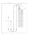
次に、併走作業時の枕地旋回の制御について図3乃至図6より説明する。まず、図3、図4に示すように、自律走行作業車両1が圃場端に至ると(S1)、作業を停止して、作業機を上昇させ(S2)、旋回動作に入る(S3)。図5に示すように、旋回が終了すると(S4)直進し(S5)、図6に示すように、設定距離Lだけ進行して待機位置に至ったか判断する(S6)。待機位置まで進行すると停止する(S7)。この待機位置は隣接行程の作業開始位置であってもよい。   Next, control of headland turning during parallel running will be described with reference to FIGS. First, as shown in FIGS. 3 and 4, when the autonomous traveling work vehicle 1 reaches the end of the field (S1), the work is stopped, the work implement is raised (S2), and the turning operation is started (S3). As shown in FIG. 5, when the turn is completed (S4), the vehicle travels straight (S5), and as shown in FIG. 6, it is determined whether the vehicle has traveled a set distance L to reach the standby position (S6). When it reaches the standby position, it stops (S7). This standby position may be a work start position in an adjacent process.

走行を停止した前記待機位置において随伴走行作業車両100の旋回終了を待つ(S8)。つまり、随伴走行作業車両100の旋回終了の判断は、第一実施例として、枕地旋回を随伴走行作業車両100に設けた操向センサ120により検知する。この場合、操向センサ120からの信号は制御装置130、通信手段を介して遠隔操作装置112に送信され、遠隔操作装置112の制御装置が枕地旋回したか判断する。枕地旋回が終了すると作業再開信号が送信され作業が再開される(S10)。枕地旋回していない場合は随伴走行作業車両100のオペレータが終了信号を発したか判断する(S9)。つまり、随伴走行作業車両100のダッシュボードまたは遠隔操作装置112に旋回終了確認スイッチ114が設けられ、オペレータが旋回終了確認スイッチ114をオンすることにより再開信号が自律走行作業車両1に送信されて自律走行作業車両1の制御装置30は枕地旋回が終了したと判断し、作業を再開する(S10)。なお、旋回終了確認スイッチ114は、オペレータが任意に操作して作業を再開できるようにするものであり、例えば、随伴走行作業車両100が旋回終了する前であっても、旋回途中であっても、旋回終了確認スイッチ114をオンすることで、強制的に旋回終了と判断させ、作業を再開させる。こうして自律走行作業車両1が待つ時間を省き作業時間の短縮化を図ることができる。なお、作業再開は走行再開も含むものである。   At the standby position where the traveling is stopped, the attendant traveling work vehicle 100 waits for the turn to end (S8). That is, the determination of the turn completion of the accompanying traveling work vehicle 100 is detected by the steering sensor 120 provided in the accompanying traveling work vehicle 100 as the first embodiment. In this case, a signal from the steering sensor 120 is transmitted to the remote operation device 112 via the control device 130 and communication means, and it is determined whether the control device of the remote operation device 112 has turned the headland. When the headland turning is completed, a work resumption signal is transmitted and the work is resumed (S10). If the headland is not turning, it is determined whether the operator of the accompanying traveling work vehicle 100 has issued an end signal (S9). In other words, the turning end confirmation switch 114 is provided on the dashboard of the accompanying traveling work vehicle 100 or the remote control device 112, and when the operator turns on the turning end confirmation switch 114, a restart signal is transmitted to the autonomous traveling work vehicle 1. The control device 30 of the traveling work vehicle 1 determines that the headland turning has ended, and resumes the work (S10). The turning end confirmation switch 114 is an operation that can be arbitrarily operated by the operator and can be resumed. For example, even before the accompanying traveling work vehicle 100 finishes turning or during turning. Then, by turning on the turn completion confirmation switch 114, it is determined that the turn is finished, and the work is resumed. In this way, it is possible to shorten the work time by omitting the time that the autonomous traveling work vehicle 1 waits. It should be noted that resuming work includes resuming traveling.

また、図4乃至図6は自律走行作業車両1と随伴走行作業車両100が併走し(左右方向に並んで走行し)、同じ作業を行い一度に二倍の幅を作業する実施形態について説明したが、図7、図8に示すように、自律走行作業車両1と随伴走行作業車両100が前後に並んで別々の作業を行う場合でも前記同様に、自律走行作業車両1が先に旋回して、設定距離Lだけ進行して待機し、図8に示すように、随伴走行作業車両100が枕地旋回を終了するのを待つように制御することも可能である。この場合、1条飛ばして旋回する。   4 to 6 illustrate an embodiment in which the autonomous traveling work vehicle 1 and the accompanying traveling work vehicle 100 travel side by side (run side by side in the left-right direction), perform the same work, and work twice the width at a time. However, as shown in FIGS. 7 and 8, even when the autonomous traveling work vehicle 1 and the accompanying traveling work vehicle 100 perform separate tasks in the front-rear direction, the autonomous traveling work vehicle 1 turns first as described above. It is also possible to perform control so that the vehicle travels by the set distance L and waits for the accompanying traveling work vehicle 100 to finish the headland turning as shown in FIG. In this case, it turns and skips 1 line.

以上のように、衛星測位システムを利用して機体の位置を測位する位置算出手段と、操舵装置を作動させる操舵アクチュエータ40と、エンジン回転制御手段となるエンジンコントローラ60と、変速手段44と、これらを制御する制御装置30とを備えた自律走行作業車両1を、前記制御装置30に記憶させた設定走行経路Rに沿って自律走行させるとともに、該自律走行作業車両1に随伴走行しながら作業を行う随伴走行作業車両100に搭載する遠隔操作装置112により自律走行作業車両1を操作可能とする併走作業車両の制御システムであって、自律走行作業車両1の制御装置30は、随伴走行作業車両100に設けた遠隔操作装置112と通信可能とされ、枕地旋回して設定距離走行すると一旦停止し、随伴走行作業車両100に設けた旋回終了確認スイッチ114の再開始信号が遠隔操作装置112を介して受信すると、あるいは、随伴走行作業車両100に設けた操向センサ120の検出値が遠隔操作装置112を介して自律走行作業車両1の制御装置30に送信され、随伴走行作業車両100が旋回して枕地旋回を終了したと認識すると、作業を再開するように制御するので、自律走行作業車両1が旋回した後に、随伴走行作業車両100と離れることなく、所定の距離を維持したまま作業が続行でき、枕地旋回の度にオペレータが自律走行作業車両1に乗り換えて旋回操作する必要がなく、作業効率を向上できる。   As described above, the position calculation means for positioning the position of the airframe using the satellite positioning system, the steering actuator 40 for operating the steering device, the engine controller 60 as the engine rotation control means, the speed change means 44, and these The autonomous traveling work vehicle 1 including the control device 30 for controlling the vehicle autonomously travels along the set traveling route R stored in the control device 30 and performs work while traveling along with the autonomous traveling work vehicle 1. A control system for a parallel running work vehicle 1 that allows the autonomous running work vehicle 1 to be operated by a remote operation device 112 mounted on the accompanying running work vehicle 100, wherein the control device 30 of the autonomous running work vehicle 1 Can be communicated with the remote control device 112 provided in the vehicle, and once the headland turns and travels a set distance, it stops temporarily and the accompanying travel work vehicle 100 When the re-start signal of the provided turning end confirmation switch 114 is received via the remote operation device 112, or the detected value of the steering sensor 120 provided on the accompanying travel work vehicle 100 is transmitted via the remote operation device 112. When it is transmitted to the control device 30 of the vehicle 1 and the accompanying traveling work vehicle 100 turns and recognizes that the headland turning has been completed, the operation is resumed. Therefore, after the autonomous traveling working vehicle 1 turns, The work can be continued while maintaining a predetermined distance without leaving the traveling work vehicle 100, and it is not necessary for the operator to change to the autonomous traveling work vehicle 1 every time the headland turns, and the work efficiency can be improved.

また、第二実施例として、随伴走行作業車両100が旋回を終了したかどうかは、随伴走行作業車両100に設けた方位センサ132の検出値が遠隔操作装置112を介して自律走行作業車両1の制御装置30に入力され、制御装置30において随伴走行作業車両100が枕地旋回したか判断される。つまり、方位センサ132により随伴走行作業車両100の進行方向を検知して、その方位から随伴走行作業車両100が圃場端でUターンして枕地旋回が終了したと判断すると、自律走行作業車両1及び随伴走行作業車両100による作業が再開される。こうして、自律走行作業車両1が旋回した後に、随伴走行作業車両100と離れることなく、所定の距離を維持したまま作業が続行でき、枕地旋回の度にオペレータが自律走行作業車両1に乗り換えて旋回操作する必要がなく、作業効率を向上できる。   In addition, as a second embodiment, whether or not the accompanying traveling work vehicle 100 has finished turning depends on whether the detected value of the azimuth sensor 132 provided on the accompanying traveling work vehicle 100 is determined by the autonomous traveling working vehicle 1 via the remote control device 112. It is input to the control device 30, and it is determined in the control device 30 whether the accompanying traveling work vehicle 100 has turned the headland. That is, when the traveling direction of the accompanying traveling work vehicle 100 is detected by the direction sensor 132 and it is determined that the accompanying traveling working vehicle 100 makes a U-turn at the end of the field and the headland turns are finished, the autonomous traveling working vehicle 1 And the work by the accompanying traveling work vehicle 100 is resumed. In this way, after the autonomous traveling work vehicle 1 turns, the work can be continued while maintaining a predetermined distance without leaving the accompanying traveling work vehicle 100, and the operator changes to the autonomous traveling work vehicle 1 each time the headland turns. There is no need to swivel, and work efficiency can be improved.

また、第三実施例として、自律走行作業車両1の斜め後方を随伴走行して作業を行う随伴走行作業車両100を撮影するようにカメラ42を自律走行作業車両1に取り付ける。例えば、キャビン11の天井の右後及び左後に取り付けて斜め後方を撮影するようにする。そして、自律走行作業車両1が圃場端に至り枕地旋回しているときは随伴走行作業車両100は撮影範囲外となる。枕地旋回状態とする。枕地旋回が終了し設定距離走行した後に停止した状態で、カメラ42で撮影した画像に随伴走行作業車両100が所定の範囲内の所定の位置に写っているか画像処理して判断する。つまり、随伴走行作業車両100が所定の撮影範囲内に写っていると、枕地旋回が終了したと判断でき、作業を再開することができる。こうして、自律走行作業車両1が旋回した後に、随伴走行作業車両100と離れることなく、所定の距離を維持したまま作業が続行でき、枕地旋回の度にオペレータが自律走行作業車両1に乗り換えて旋回操作する必要がなく、作業効率を向上できる。   Further, as a third embodiment, the camera 42 is attached to the autonomous traveling work vehicle 1 so as to photograph the accompanying traveling work vehicle 100 that performs the work while traveling obliquely behind the autonomous traveling work vehicle 1. For example, it is attached to the right rear and the left rear of the ceiling of the cabin 11 so as to photograph an oblique rear side. Then, when the autonomous traveling work vehicle 1 reaches the end of the field and makes a headland turn, the accompanying traveling work vehicle 100 is out of the imaging range. The headland turns. In a state where the headland turn is completed and the vehicle has stopped after traveling a set distance, it is determined by performing image processing whether the accompanying traveling work vehicle 100 is reflected in a predetermined position within a predetermined range in the image captured by the camera 42. That is, if the accompanying traveling work vehicle 100 is in the predetermined shooting range, it can be determined that the headland turning has ended, and the work can be resumed. In this way, after the autonomous traveling work vehicle 1 turns, the work can be continued while maintaining a predetermined distance without leaving the accompanying traveling work vehicle 100, and the operator changes to the autonomous traveling work vehicle 1 each time the headland turns. There is no need to swivel, and work efficiency can be improved.

前記自律走行作業車両の制御装置は、随伴走行作業車両に設けた遠隔操作装置と通信可能とされ、枕地旋回して設定距離走行すると一旦停止し、前記随伴走行作業車両に設けた作業機昇降検知手段の検出値が遠隔操作装置を介して自律走行作業車両の制御装置に送信され、随伴走行作業車両が旋回する前に作業機を上昇し、枕地旋回を終了して作業機を下げたときに枕地旋回の終了と認識すると、作業を再開するように制御する。こうして、自律走行作業車両1が旋回した後に、随伴走行作業車両100と離れることなく、所定の距離を維持したまま作業が続行でき、枕地旋回の度にオペレータが自律走行作業車両1に乗り換えて旋回操作する必要がなく、作業効率を向上できる。また、作業機昇降検知手段はハンドルポストに設けた昇降スイッチ、または、作業機耕深制御を行うときに利用するリフトアームの回動角センサを利用することで、部品点数を増加することなく、ソフトの追加で実現することができる。   The control device for the autonomous traveling work vehicle is capable of communicating with a remote control device provided in the accompanying traveling work vehicle, temporarily stops when the headland turns and travels a set distance, and the working machine provided in the accompanying traveling work vehicle is raised and lowered. The detection value of the detection means is transmitted to the control device of the autonomous traveling work vehicle via the remote control device, and the working machine is raised before the accompanying traveling working vehicle turns, the headland turning is finished, and the working machine is lowered. When it is recognized that the headland turning has ended, control is performed to resume the work. In this way, after the autonomous traveling work vehicle 1 turns, the work can be continued while maintaining a predetermined distance without leaving the accompanying traveling work vehicle 100, and the operator changes to the autonomous traveling work vehicle 1 each time the headland turns. There is no need to swivel, and work efficiency can be improved. Also, the work implement lifting detection means uses a lift switch provided on the handle post or a lift arm rotation angle sensor used when working machine plowing control is performed, so that the number of parts can be increased without increasing the number of parts. It can be realized by adding.

前記自律走行作業車両の制御装置は、随伴走行作業車両に設けた遠隔操作装置と通信可能とされ、枕地旋回して設定距離走行すると一旦停止し、前記随伴走行作業車両に設けた走行速度検知手段の検出値が遠隔操作装置を介して自律走行作業車両の制御装置に送信され、随伴走行作業車両が速度を落として旋回し停止したときを枕地旋回の終了として認識すると、作業を再開するように制御する。こうして、自律走行作業車両1が旋回した後に、随伴走行作業車両100と離れることなく、所定の距離を維持したまま作業が続行でき、枕地旋回の度にオペレータが自律走行作業車両1に乗り換えて旋回操作する必要がなく、作業効率を向上できる。また、走行速度検知手段は走行制御で利用する速度センサを利用することで、部品点数を増加することなく、ソフトの追加で実現することができる。   The control device for the autonomous traveling work vehicle is capable of communicating with a remote control device provided in the accompanying traveling work vehicle, temporarily stops when the headland turns and travels a set distance, and a traveling speed detection provided in the accompanying traveling work vehicle. When the detected value of the means is transmitted to the control device of the autonomous traveling work vehicle via the remote control device and the accompanying traveling work vehicle turns and stops at a reduced speed, the work is resumed when the end of the headland turning is recognized. To control. In this way, after the autonomous traveling work vehicle 1 turns, the work can be continued while maintaining a predetermined distance without leaving the accompanying traveling work vehicle 100, and the operator changes to the autonomous traveling work vehicle 1 each time the headland turns. There is no need to swivel, and work efficiency can be improved. Further, the traveling speed detecting means can be realized by adding software without increasing the number of parts by using a speed sensor used in traveling control.

1 自律走行作業車両
30 制御装置
40 操舵アクチュエータ
42 カメラ
44 変速手段
60 エンジンコントローラ
100 随伴走行作業車両
112 遠隔操作装置
114 旋回終了確認スイッチ
120 操向センサ
132 方位センサ
DESCRIPTION OF SYMBOLS 1 Autonomous traveling work vehicle 30 Control apparatus 40 Steering actuator 42 Camera 44 Shift means 60 Engine controller 100 Accompanied traveling work vehicle 112 Remote control device 114 Turning completion confirmation switch 120 Steering sensor 132 Direction sensor

Claims (6)

衛星測位システムを利用して自律走行作業車両の位置を測位する位置算出手段と、操舵装置を作動させる操舵アクチュエータと、エンジン回転制御手段と、変速手段と、各部を制御して設定走行経路に沿って前記自律走行作業車両を自律走行させる制御装置と、前記自律走行作業車両の後方を走行する随伴走行作業車両に搭載可能であると共に前記制御装置に再開始信号を送信可能な遠隔操作装置と、を備え、
前記制御装置は、前記自律走行作業車両が設定走行経路に沿って枕地旋回させた後に自律走行作業車両を一定距離直進させて一旦停止し、前記一旦停止させた後に前記遠隔操作装置から再開始信号を受信したときは、前記自律走行作業車両と前記随伴走行作業車両との位置関係の如何を問わず、前記自律走行作業車両の自律走行を再開させることが可能であることを特徴とする随伴作業システム。
A position calculating means for positioning the position of the autonomous traveling work vehicle using the satellite positioning system, a steering actuator for operating the steering device, an engine rotation control means, a speed change means, and each part are controlled to follow the set traveling route. A control device that autonomously travels the autonomous traveling work vehicle, a remote operation device that can be mounted on an accompanying traveling work vehicle that travels behind the autonomous traveling work vehicle and can transmit a restart signal to the control device, With
The control device, after the autonomous traveling work vehicle turns the headland along the set traveling route, linearly travels the autonomous traveling work vehicle for a certain distance, temporarily stops, and then restarts from the remote control device after the temporary stop. When the signal is received, the autonomous traveling of the autonomous traveling work vehicle can be resumed regardless of the positional relationship between the autonomous traveling working vehicle and the accompanying traveling working vehicle. Work system.
前記制御装置は、前記遠隔操作装置から再開始信号を受信する前に、前記遠隔操作装置から随伴走行作業車両の枕地旋回終了信号を受信した場合は、前記自律走行作業車両の自律走行を再開させることを特徴とする請求項1に記載の随伴作業システム。If the control device receives a headland turn end signal of an accompanying traveling work vehicle from the remote control device before receiving a restart signal from the remote control device, the control device resumes autonomous traveling of the autonomous traveling work vehicle. The accompanying work system according to claim 1, wherein: 前記制御装置は、前記遠隔操作装置から再開始信号を受信する前に、前記遠隔操作装置から取得した前記随伴走行作業車両の走行状態を示す信号に基づいて随伴走行作業車両の枕地旋回が終了したと判断した場合は、前記自律走行作業車両の自律走行を再開させることを特徴とする請求項1に記載の随伴作業システム。Before the control device receives the restart signal from the remote operation device, the headland turning of the accompanying travel work vehicle is completed based on the signal indicating the traveling state of the accompanying travel work vehicle acquired from the remote operation device. 2. The accompanying work system according to claim 1, wherein, when it is determined that the autonomous running work vehicle is autonomous, the autonomous running work vehicle is resumed. 前記随伴走行作業車両の走行状態を示す信号は、前記随伴走行作業車両が備える操向センサまたは方位センサまたは車速センサの検出値を示す信号であることを特徴とする請求項3に記載の随伴作業システム。The accompanying work according to claim 3, wherein the signal indicating the traveling state of the accompanying traveling work vehicle is a signal indicating a detected value of a steering sensor, a direction sensor, or a vehicle speed sensor included in the accompanying traveling working vehicle. system. 前記随伴走行作業車両の走行状態を示す情報は、前記随伴走行作業車両が備えるカメラの映像情報を示す信号であることを特徴とする請求項3に記載の随伴作業システム。4. The accompanying work system according to claim 3, wherein the information indicating the traveling state of the accompanying traveling work vehicle is a signal indicating video information of a camera included in the accompanying traveling work vehicle. 前記随伴走行作業車両の走行状態を示す情報は、前記随伴走行作業車両が備える作業機の昇降を検知する作業機昇降検知手段から出力される上昇信号及び下降信号であることを特徴とする請求項3に記載の随伴作業システム。The information indicating the traveling state of the accompanying traveling work vehicle is an ascending signal and a descending signal output from a work implement raising / lowering detecting unit that detects elevation of a working implement included in the accompanying traveling work vehicle. The accompanying work system according to 3.
JP2014135416A 2014-06-30 2014-06-30 Accompanying work system Active JP6163460B2 (en)

Priority Applications (1)

Application Number Priority Date Filing Date Title
JP2014135416A JP6163460B2 (en) 2014-06-30 2014-06-30 Accompanying work system

Applications Claiming Priority (1)

Application Number Priority Date Filing Date Title
JP2014135416A JP6163460B2 (en) 2014-06-30 2014-06-30 Accompanying work system

Related Parent Applications (1)

Application Number Title Priority Date Filing Date
JP2014063717 Division 2014-03-26 2014-03-26

Publications (2)

Publication Number Publication Date
JP2015186473A JP2015186473A (en) 2015-10-29
JP6163460B2 true JP6163460B2 (en) 2017-07-12

Family

ID=54429144

Family Applications (1)

Application Number Title Priority Date Filing Date
JP2014135416A Active JP6163460B2 (en) 2014-06-30 2014-06-30 Accompanying work system

Country Status (1)

Country Link
JP (1) JP6163460B2 (en)

Families Citing this family (7)

* Cited by examiner, † Cited by third party
Publication number Priority date Publication date Assignee Title
JP6716910B2 (en) * 2015-12-25 2020-07-01 井関農機株式会社 Autonomous traveling system for work vehicles
US10149468B2 (en) 2016-05-10 2018-12-11 Crinklaw Farm Services, Inc. Robotic agricultural system and method
US9877470B2 (en) 2016-05-10 2018-01-30 Crinklaw Farm Services, Inc. Robotic agricultural system and method
ES2958557T3 (en) 2016-08-29 2024-02-09 Guss Automation Llc Robotic farming system and method
JP7016747B2 (en) * 2018-03-28 2022-02-07 ヤンマーパワーテクノロジー株式会社 Collaborative work system
JP7320093B2 (en) * 2019-01-31 2023-08-02 ヤンマーパワーテクノロジー株式会社 Automatic driving system for work vehicles
EP3954190A4 (en) * 2019-04-09 2023-01-04 FJ Dynamics Technology Co., Ltd Image acquisition device and processing method for agricultural harvesting operation machine

Family Cites Families (7)

* Cited by examiner, † Cited by third party
Publication number Priority date Publication date Assignee Title
JP3016836B2 (en) * 1990-08-20 2000-03-06 ヤンマー農機株式会社 Control device for self-propelled trailer that follows work vehicle
JP3243648B2 (en) * 1991-12-03 2002-01-07 ヤンマー農機株式会社 Travel control system for mobile agricultural machines
JPH1139036A (en) * 1997-07-23 1999-02-12 Kubota Corp Travel controller for work vehicle
NL1007225C2 (en) * 1997-10-08 1999-04-09 Maasland Nv Vehicle combination.
JP2006018675A (en) * 2004-07-02 2006-01-19 Kubota Corp Automation structure for mobile work machine
DE102006015203A1 (en) * 2006-03-30 2007-11-15 Claas Selbstfahrende Erntemaschinen Gmbh Method for controlling agricultural machine systems
US8738238B2 (en) * 2009-11-12 2014-05-27 Deere & Company Coordination of vehicle movement in a field

Also Published As

Publication number Publication date
JP2015186473A (en) 2015-10-29

Similar Documents

Publication Publication Date Title
JP6368964B2 (en) Control device for work vehicle
JP6339427B2 (en) Parallel work system
JP6267626B2 (en) Travel route setting device
JP6163460B2 (en) Accompanying work system
JP6239441B2 (en) Work vehicle parallel running system
JP6450948B2 (en) Autonomous traveling work vehicle
JP6078025B2 (en) Parallel work system
KR20170037985A (en) Remote control apparatus
WO2015118731A1 (en) Control device for parallel travel work system
JP6267627B2 (en) Operation terminal
JP6267586B2 (en) Display device
JP2016095660A (en) Unmanned operation system
WO2015118730A1 (en) Remote operation device for parallel travel work system
JP6296926B2 (en) Parallel work system
JP2017174229A (en) Route generation device
JP2015222499A (en) Emergency stop system
JP2016095659A (en) Plurality-of-vehicles accompanying travel work system
JP6297436B2 (en) Parallel work system
JP2015222503A (en) Autonomous travel working vehicle
JP7065170B2 (en) Autonomous driving system
JP6258782B2 (en) Monitor device
JP2015222500A (en) Emergency stop system
JP6258781B2 (en) Emergency stop device
JP2015222502A (en) Emergency stop system
JP6618056B2 (en) Work system

Legal Events

Date Code Title Description
A621 Written request for application examination

Free format text: JAPANESE INTERMEDIATE CODE: A621

Effective date: 20160229

A131 Notification of reasons for refusal

Free format text: JAPANESE INTERMEDIATE CODE: A131

Effective date: 20161129

A521 Request for written amendment filed

Free format text: JAPANESE INTERMEDIATE CODE: A523

Effective date: 20170118

TRDD Decision of grant or rejection written
A01 Written decision to grant a patent or to grant a registration (utility model)

Free format text: JAPANESE INTERMEDIATE CODE: A01

Effective date: 20170613

A61 First payment of annual fees (during grant procedure)

Free format text: JAPANESE INTERMEDIATE CODE: A61

Effective date: 20170619

R150 Certificate of patent or registration of utility model

Ref document number: 6163460

Country of ref document: JP

Free format text: JAPANESE INTERMEDIATE CODE: R150

R250 Receipt of annual fees

Free format text: JAPANESE INTERMEDIATE CODE: R250

S533 Written request for registration of change of name

Free format text: JAPANESE INTERMEDIATE CODE: R313533

R350 Written notification of registration of transfer

Free format text: JAPANESE INTERMEDIATE CODE: R350