JP6157101B2 - Robot equipment - Google Patents
Robot equipment Download PDFInfo
- Publication number
- JP6157101B2 JP6157101B2 JP2012272339A JP2012272339A JP6157101B2 JP 6157101 B2 JP6157101 B2 JP 6157101B2 JP 2012272339 A JP2012272339 A JP 2012272339A JP 2012272339 A JP2012272339 A JP 2012272339A JP 6157101 B2 JP6157101 B2 JP 6157101B2
- Authority
- JP
- Japan
- Prior art keywords
- force sensor
- contact portion
- axis direction
- robot
- robot arm
- Prior art date
- Legal status (The legal status is an assumption and is not a legal conclusion. Google has not performed a legal analysis and makes no representation as to the accuracy of the status listed.)
- Active
Links
Images


Description
本発明は、ロボットアームを有するロボット装置に関する。 The present invention relates to a robot apparatus having a robot arm.
近年、より生産効率の高い生産装置としてロボットアームを用いた生産装置が使用されている。所望の製品を生産するにあたり、ロボットハンドが装着されたロボットアームによって、構成部品をピックアップし、部品同士を組み付けることで製品を高速かつ長時間にわたって休止することなく生産することが可能である。 In recent years, a production apparatus using a robot arm has been used as a production apparatus with higher production efficiency. In producing a desired product, it is possible to produce a product at high speed without taking a pause for a long time by picking up the component parts and assembling the parts with a robot arm to which a robot hand is attached.
ロボットアームをさらに精密に動作させるため、ロボットアームに力覚センサまたは加重によって生じた歪を検知する変位センサを取り付け、検知した力または歪に応じてロボットアームをフィードバック制御することで、高い精度での力制御および位置制御する技術が知られている。 In order to operate the robot arm more precisely, a force sensor or a displacement sensor that detects strain caused by weighting is attached to the robot arm, and feedback control of the robot arm is performed according to the detected force or strain. Techniques for controlling the force and the position of the motor are known.
特許文献1記載のハンドリング装置〔ロボットアーム9では、変位センサがロボットアームとグリッパ(ハンド)との間〕に設けられており、組み付け時にグリッパに加わった加重による歪を、変位センサで検知することでロボットアームやグリッパのフィードバック制御を行っている。 The handling device described in Patent Document 1 (in the robot arm 9, the displacement sensor is provided between the robot arm and the gripper (hand)), and the displacement sensor detects strain caused by weight applied to the gripper during assembly. The robot arm and gripper feedback control.
特許文献2に記載されているように力覚センサには過度な力が加わった際の破損を防止する機構が提案されている。
As described in
特許文献2に記載の力覚センサでは台座で支持された導電性のダイアフラム部に対して、その下方に配置された土台部の上面に電極が設けられている。ダイアフラム部の上面には、柱状接続部を介して盤状受力体が接続されており、盤状受力体に外力が作用するとダイアフラム部が撓むので、各電極との間の静電容量値に基づいて外力の検出を行う。盤状受力体には、下層孔部および上層孔部が設けられており、これら各孔部内に支柱部材およびストッパー部材が配置されている。支柱部材の下端は力覚センサの台座に固着されている。盤状受力体の変位は、台座の上面およびストッパー部材によって制限される。したがって、ダイアフラム部が破損しないように、盤状受力体とダイアフラム部との相対変位を規制する強固な構造を有することで過度な外力が作用しても、ダイアフラム部に損障が生じない構造になっている。
In the force sensor described in
しかしながら、力覚センサが単体として強固な構造をとる力覚センサをロボットアームに搭載した場合、力覚センサ自体は破損しないものの、ロボットアームとの連結部を介してロボットアームに強い内部応力が加わった場合に、ロボットアームの構成部品に変形が生じる場合がある。ロボットアームの自由端とエンドエフェクタの間に設けられる構造体は連結構造が複雑で変形が起きやすい。 However, when a force sensor that has a strong structure as a single unit is mounted on the robot arm, the force sensor itself is not damaged, but strong internal stress is applied to the robot arm through the connection with the robot arm. In such a case, the components of the robot arm may be deformed. The structure provided between the free end of the robot arm and the end effector has a complicated connection structure and is easily deformed.
本発明の目的は、過度の外力やモーメントに対して、ロボットアームの保護も考慮した、力覚センサを搭載したロボットアームを有するロボット装置を提供することにある。 An object of the present invention is to provide a robot apparatus having a robot arm on which a force sensor is mounted in consideration of protection of the robot arm against an excessive external force or moment.
特に、本発明の目的は、強い外力が加わった場合には所定の部品を誘導的に破損し、高価なロボットアームの大規模な破損を回避し得るロボット装置を提供することにある。 In particular, an object of the present invention is to provide a robot apparatus capable of inductively damaging a predetermined part when a strong external force is applied and avoiding a large-scale breakage of an expensive robot arm.
本発明のロボット装置は、ロボットアームと、前記ロボットアームに取り付けられている力覚センサと、前記力覚センサに、結合部材を介して取り付けられているエンドエフェクタと、結合部材を介して取り付けられているエンドエフェクタと、を有し、前記ロボットアームまたは前記力覚センサから前記エンドエフェクタに向かうZ軸方向に突出する第一の当接部と、前記エンドエフェクタから前記ロボットアームまたは前記力覚センサに向かうZ軸方向に突出する第二の当接部と、前記ロボットアームまたは前記力覚センサから前記エンドエフェクタに向かうZ軸方向に突出する第三の当接部と、前記エンドエフェクタから前記ロボットアームまたは前記力覚センサに向かうZ軸方向に突出する第四の当接部と、をさらに有し、前記第一の当接部および前記第二の当接部は、前記Z軸方向と垂直なX軸方向に所定のクリアランスをもって対向して設置され、前記第三の当接部および前記第四の当接部は、前記Z軸方向および前記X軸方向と垂直なY軸方向に所定のクリアランスをもって対向して設置されていることを特徴とする。 A robot apparatus according to the present invention is attached to a robot arm, a force sensor attached to the robot arm, an end effector attached to the force sensor via a coupling member, and a coupling member. A first abutting portion protruding in the Z-axis direction from the robot arm or the force sensor toward the end effector, and the robot arm or the force sensor from the end effector. A second contact portion projecting in the Z-axis direction toward the Z-axis, a third contact portion projecting in the Z-axis direction from the robot arm or the force sensor toward the end effector, and the robot from the end effector to the robot A fourth contact portion projecting in the Z-axis direction toward the arm or the force sensor, and The contact portion and the second contact portion are disposed to face each other with a predetermined clearance in the X-axis direction perpendicular to the Z-axis direction, and the third contact portion and the fourth contact portion are Further, they are arranged to face each other with a predetermined clearance in the Z-axis direction and the Y-axis direction perpendicular to the X-axis direction .
本発明は、ロボット装置に過度な外力が加わることによる力覚センサの破損を抑制するとともに、特定の方向の力やモーメントに対しては結合部材が優先的に破損されるような構造であることによってロボットアームの大規模な破損を抑制したロボット装置を提供することが可能である。 The present invention has a structure in which the force sensor is prevented from being damaged by excessive external force applied to the robot apparatus, and the coupling member is preferentially damaged with respect to a force or moment in a specific direction. Thus, it is possible to provide a robot apparatus that suppresses large-scale breakage of the robot arm.
以下、図面を参照しながら本発明のロボット装置に関して説明する。 Hereinafter, the robot apparatus of the present invention will be described with reference to the drawings.
図1は本発明のロボット装置の外観図を示す。不図示の台座や床に設置されたロボットアーム1の自由端に対して、力覚センサ2が連結されていて、さらに力覚センサ2とエンドエフェクタとしてのロボットハンド3が連結されている。ロボット装置による作業によってロボットハンド3に外力が加わり、外力は力覚センサ2に伝達し検出される。
FIG. 1 is an external view of a robot apparatus according to the present invention. A
力覚センサ2としては、磁気式力覚センサ、静電容量式力覚センサ、歪ゲージ式力覚センサの如き力覚センサが使用される。以下では、磁石の如き磁束発生源とホール素子の如き磁電変換素子の対からなる磁気式力覚センサを使用することが可能である。
As the
また、ロボットアームの自由端と力覚センサ2とエンドエフェクタを結ぶ方向をZ軸方向とし、Z軸方向と交差する異なる方向にそれぞれX軸方向、Y軸方向をとるものとすると、ロボットハンド3や、力覚センサ2に加わる外力は、Fx、Fy、Fzと、モーメントはMx、My、Mzとの6成分がそれぞれ加重されることになる。用途に応じて、上述の6成分のうちの3成分を検出する3軸センサや6軸センサなど、様々な型式のセンサを使用することが可能である。
If the direction connecting the free end of the robot arm, the
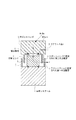
図2は、本発明のロボット装置の構造の概略的説明図である。ロボットアームの自由端に力覚センサ2が連結され、さらに深皿状の形状の結合部材4を介して力覚センサ2とロボットハンド3が連結されている。結合部材4はZ軸に対して軸対称な部材で構成されており、力覚センサ2と面接触して連結される底部と、底部に対して径方向に突出したフランジで形成されており、フランジとロボットハンド3とが図のようにボルト等で結合されている。
FIG. 2 is a schematic explanatory diagram of the structure of the robot apparatus of the present invention. The
結合部材4は、ロボットハンド3及び力覚センサ2の降伏点に対応するひずみより小さなひずみで降伏する。結合部材4は、ロボットハンド3と力覚センサ2は連結するとともに、過度な外力に対して、誘導的に破損する役割を担っている。
The coupling member 4 yields with a strain smaller than the strain corresponding to the yield point of the robot hand 3 and the
以下の説明では、応力、ひずみ及び降伏の用語を使用して説明をおこなう。 In the following description, the terms stress, strain and yield will be used.
結合部材4に外力が加わると、加重の大きさに応じてひずみが生じ応力が上昇する。加わる外力の大きさが増大するにつれて、ひずみに対して線形に応力が上昇する。このように、ひずみに対して線形に応力が上昇する弾性域では、外力が無くなるとひずみも元に戻る弾性的な変形が結合部材4に生じる。 When an external force is applied to the coupling member 4, a strain is generated according to the magnitude of the load, and the stress increases. As the magnitude of the applied external force increases, the stress increases linearly with respect to the strain. As described above, in the elastic region where the stress rises linearly with respect to the strain, when the external force is lost, the coupling member 4 undergoes an elastic deformation that returns the strain to its original state.
一方、強い外力によってひずみがある大きさを超えると降伏が生じ、外力によって結合部材4に生じた変形が元に戻らなくなる(塑性域)。この弾性域と塑性域の境界は降伏点と呼ばれる。 On the other hand, when the strain exceeds a certain magnitude due to a strong external force, yielding occurs, and the deformation generated in the coupling member 4 due to the external force cannot be restored (plastic region). The boundary between this elastic region and the plastic region is called the yield point.
また、ロボットアームに固定された第一の当接部5と、ロボットハンドに固定された第二の当接部6とがX軸方向に沿って互いに対向するように設けられている。これらは、力覚センサ2が破損せずに構造的に許容できるX軸方向への変形δxに対して小さいクリアランスΔx(Δx≦δx)を設けて対向している。クリアランスΔxを調整するためにさらに第一の当接部5または第二の当接部6の一方にX軸方向に沿ってネジ部を設けてネジの先端と他方の当接部との距離(クリアランスΔx)を調整させる構造をとっても良い。
Also, a
つまり、第一の当接部5及び第二の当接部6は、エンドエフェクタであるロボットハンドとロボットアームとの相対位置の変化が力覚センサのX軸方向に対する歪の限度より小さくなるように間隔(クリアランスΔx)が設けられている。
That is, the
第一の当接部5及び第二の当接部6は、過度なX軸方向の成分を有する外力が加わった場合に、互いに接触し、変位が規制されるストッパーとして機能する。
The
さらに、図2では不図示の紙面手前から奥に向かってのY軸方向に沿って同じくロボットアームに固定された第三の当接部7と、ロボットハンドに固定された第四の当接部8を設けても良い。 Further, in FIG. 2, a third contact portion 7 fixed to the robot arm along the Y-axis direction from the front side to the back side (not shown) and a fourth contact portion fixed to the robot hand. 8 may be provided.
ロボットハンド3に加わった力Fx、Fyに対しては、当接部がストッパーとして機能するため所定の大きさ以上のロボットハンド3とロボットアーム1との相対位置の変化は規制され、結果として結合部材4の変形は生じ難い。 For the forces Fx and Fy applied to the robot hand 3, the contact portion functions as a stopper, so that the change in the relative position between the robot hand 3 and the robot arm 1 of a predetermined size or more is restricted, resulting in the combination The deformation of the member 4 is difficult to occur.
一方、モーメントMx、Myに対しては結合部材4の底部が屈曲しやすいため、過度の大きさのモーメントMx、Myに対しては、結合部材4が降伏し、破損しやすい構造となっている。力覚センサ及びロボットハンドの降伏点に対応するひずみより小さなひずみで結合部材4は降伏するので、過度なモーメントが加わった際に結合部材4が優先的に変形し、破損する。 On the other hand, since the bottom of the coupling member 4 is easily bent with respect to the moments Mx and My, the coupling member 4 yields and is easily damaged when the moments Mx and My are excessively large. . Since the coupling member 4 yields with a strain smaller than the strain corresponding to the yield point of the force sensor and the robot hand, the coupling member 4 is preferentially deformed and damaged when an excessive moment is applied.
したがって、結合部材4および上述の当接部を具備することで、Fx、Fyの外力に強く、Mx,Myに対して結合部材4が犠牲的な破損を起こすような、外力に対して選択的な力感受性を持つロボット装置を提供することが可能である。 Therefore, by providing the coupling member 4 and the above-described contact portion, it is strong against the external force of Fx and Fy, and is selective to an external force that causes the sacrificial breakage of the coupling member 4 with respect to Mx and My. It is possible to provide a robot apparatus having a high force sensitivity.
また、単に力覚センサやロボットハンドを高強度に構成するよりも、本発明は、ロボット装置の構成要素の保護特性の良好なロボット装置を提供することが可能である。 In addition, the present invention can provide a robot apparatus with better protection characteristics of the components of the robot apparatus than simply configuring the force sensor and the robot hand with high strength.
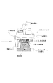
図3(a)は、本実施形態をより具体的に示している説明図である。図3(a)は、説明図中の左側断面を切り欠いて描いている。ロボットアームの自由端を台座として力覚センサ2が設けられ、力覚センサ2に対してその周囲に柱部材が複数配置されており、複数の柱部材によって天面9を支持している。また、天面9には中央に開口が設けられており、この開口を通して力覚センサ2、結合部材4、ロボットハンド3が接続されている。天面9には天面の表面に沿って突出して第一の当接部5が設けられている。力覚センサ2は結合部材4を介してフィンガーを備えたエンドエフェクタとしてのロボットハンド3に連結されている。ロボットハンド3には第二の当接部6が設けられており、天面9に設けられた第一の当接部5と対向して配置されている。天面9はロボットハンドとは間隔をあけて配置されており接触しないように配置されている。図3(a)におけるA−A断面を図3(b)に示す。第一の当接部5は、2個(5a、5b)設けられており、第二の当接部6は、2個(6a、6b)設けられており、第三の当接部7(7a、7b)設及び第四の当接部8もしれぞれ2個(8a、8b)設けられている。第一の当接部5(5a,5b)及び第二の当接部6(6a,6b)は、X軸方向に沿って所定のクリアランスΔxを設けて対向して設置されており、第三の当接部7(7a,7b)及び第四の当接部(8a,8b)は、Y軸方向に沿って所定のクリアランスΔyを設けて対向して設置されている。第一、第二、第三、第四の当接部によって外力Fxおよび外力Fyによる過負荷が生じても、対向して設けられた当接部がストッパーとして機能し、力覚センサ2を破損させるほどの力が力覚センサ2に加わることを抑制する。
FIG. 3A is an explanatory diagram showing the embodiment more specifically. FIG. 3A is drawn by cutting out the left cross section in the explanatory diagram. A
また、ロボットアームに連結された天面9に設けられた第一の当接部5及び第三の当接部7と、ロボットハンドに固定された第二の当接部6及び第三の当接部8とが、紙面の手前と奥を結ぶZ軸方向を回転軸として回転の方向に沿って、順に、第一の当接部5、第二の当接部6、第四の当接部8、第三の当接部7が設けられている。この配置は、回転の方向に沿って、順に、第二の当接部6、第一の当接部5、第三の当接部7、第四の当接部8が設けられていてもよい。
In addition, the
このような構成をとると、X軸方向およびY軸方向に対する変位に対するストッパー機能に加え、Z軸方向を回転軸とする回転に対して、時計回り、反時計回り、いずれの方向に対する回転に関しても変位が規制されるためモーメントMzに対するストッパー機能をも備えた構造とすることができる。 With such a configuration, in addition to a stopper function against displacement in the X-axis direction and the Y-axis direction, in addition to rotation about the Z-axis direction as a rotation axis, clockwise, counterclockwise, and rotation in any direction. Since the displacement is restricted, a structure having a stopper function for the moment Mz can be obtained.
このような当接部を備え、連結部材4を備えたロボット装置は、Fx、Fy、Mzに対する過度な力による力覚センサの破損を抑制しつつ、Mx方向や、Myの方向に過度なモーメントが加わった場合には、結合部材4が破損する。したがって、力覚センサやロボットハンド、ロボットアームのフレームに変形や歪みが生じることを抑制できる。ロボットアームの如き長手状の装置は、長手方向に対して交差する方向のモーメント成分であるMx、Myに対しては弾性域が狭く、比較的小さなひずみで降伏、変形しやすい。したがって、このようなモーメント成分に対しては犠牲的に破損し、交換が容易な部品をロボット装置に組み込んでおくことで、効果的にロボット装置を構成するロボットアームやロボットハンドの如き精密機器の破損を抑制できる。また生産用途に用いられるロボット装置の如く、高い稼働率が求められる装置において、不測の外力の印加による稼働停止トラブルが起きたとしても容易に部品交換して迅速に復旧できるメリットがある。 The robot apparatus including such a contact portion and the connecting member 4 has an excessive moment in the Mx direction and the My direction while suppressing damage to the force sensor due to an excessive force with respect to Fx, Fy, and Mz. When is added, the connecting member 4 is damaged. Therefore, it is possible to suppress deformation and distortion of the force sensor, the robot hand, and the robot arm frame. A longitudinal device such as a robot arm has a narrow elastic range with respect to Mx and My, which are moment components in a direction crossing the longitudinal direction, and easily yields and deforms with a relatively small strain. Therefore, such a moment component is damaged at the sacrifice, and parts that can be easily replaced are incorporated in the robot apparatus, so that the precision of the precision device such as the robot arm or robot hand that effectively constitutes the robot apparatus can be reduced. Damage can be suppressed. Further, in a device that requires a high operation rate, such as a robot device used for production purposes, there is an advantage that even if an operation stoppage trouble due to unexpected application of external force occurs, parts can be easily replaced and recovered quickly.
図4は、本実施形態のロボット装置が稼働時にクラッシュ等で不測の強い外力がフィンガーに加わった場合の様子を示す図である。例えば、ロボットの軌道上に誤配置された冶具や部品などの予期せぬ障害物にロボット装置が衝突しクラッシュすると、力覚センサ2にとって過負荷なモーメントMyがフィンガーに印加される場合がある。
FIG. 4 is a diagram illustrating a state where an unexpectedly strong external force is applied to the finger due to a crash or the like during operation of the robot apparatus of the present embodiment. For example, when the robot apparatus collides with an unexpected obstacle such as a jig or a part misplaced on the robot trajectory and crashes, an overload moment My for the
その時、ロボットハンド3は、ロボットアームの自由端に対して大きく姿勢が変化する。姿勢の変化に伴って、第一の当接部5と第二の当接部6とが接触し、X軸方向に沿っての変位は規制されるため力覚センサ2には、力覚センサ2が破損するほどの力が印加されることは抑制される。一方で、モーメントMyが印加されたことによる姿勢の変化によって結合部材4の底部に大きな力が加わり屈曲・破損する。このようなクラッシュが起きた際には、ただちにロボット装置が停止され、点検・復旧が行われる。結合部材4は、力覚センサ2とロボットハンド3の間に設けられた部品であり、ロボットハンド3を力覚センサ2から脱離させ、結合部材4を交換の上再びロボットハンド3を装着し、復旧させる。
At that time, the posture of the robot hand 3 changes greatly with respect to the free end of the robot arm. As the posture changes, the
一方、図4に示すようなロボットハンド3のフィンガーの台座に相当する位置に過負荷FxがX軸方向に沿って印加される場合、すなわち加わった加重の作用線と力覚センサ2との距離が比較的短い場合がある。この場合には、モーメントではなくX軸方向に沿った並進方向の加重が加わった場合は第一の当接部5及び第二の当接部6が接触してストッパー機能を果たす。
On the other hand, when an overload Fx is applied along the X-axis direction at a position corresponding to the finger base of the robot hand 3 as shown in FIG. 4, that is, the distance between the applied action line of the applied weight and the
<力覚センサについて>
本実施形態において好適に力覚センサ2の一例として、磁気式力覚センサについて以下に説明する。
<About force sensor>
A magnetic force sensor will be described below as an example of the
図5(a)は、磁気式力覚センサの概略的な断面図を示す図である。センシング部は筒状の筐体12の内部に収められている。
FIG. 5A is a schematic cross-sectional view of a magnetic force sensor. The sensing unit is housed in a
磁気式力覚センサは、外部からの力が作用する作用部14と、作用部14の力を変位に変換する弾性体15と、第1の磁電変換素子11と、第2の磁電変換素子12が実装される基板16と、複数の磁石から構成される磁束発生源17とを有している。基板16に実装される磁電変換素子11,12は十字形の作用部14に固定され、作用部14は環状の弾性体15を介して柱状構造体を、間隔をあけて環状部材に配置した支持部材20に変位可能に支持されている。さらに、基板16に配された磁電変換素子11,12の出力は不図示の配線を介して出力をA/D変換する変換部109に送信される。さらに、磁気式力覚センサは演算部110および記憶部111を有している。また、磁束発生源を構成する第1の磁石に対向する位置に第1の磁電変換素子が配置され、磁束発生源を構成する第1の磁石及び前記第2の磁石との境界に近い側に第2の磁電変換素子が配置されている。
The magnetic force sensor includes an
作用部14と弾性体15及び支持部材20は互いに一体に形成されていてもよいし、図のように各部材ごとに構成されていてもよい。また、支持部材20は円筒状部材など様々な形状が取り得るが、作用部14を支持できるものであればどのような構成でもよい。
The
つまり外力に対して磁電変換素子と磁束発生源との相対位置を変化できる構成であればどのような構成を採用してもよい。本実施形態ではSUS等の強度の高い部材で弾性体15や筐体12を形成している。
That is, any configuration may be adopted as long as the relative position between the magnetoelectric conversion element and the magnetic flux generation source can be changed with respect to the external force. In the present embodiment, the
図5(b)は、磁気式力覚センサのセンシング部(検出部)の斜視図である。本発明においては、力のセンシングに関係する第1磁電変換素子11と第2磁電変換素子12と磁束発生源17とを併せてセンシング部と称する。センシング部は以下で説明する作用部14と磁束発生源17との相対位置を、検知した磁場を電気信号に変換して検出する機能を果たす。センシング部は、磁石の磁極面に対向して配置された第1磁電変換素子11a〜11dと、第1磁電変換素子の間に配置された第2磁電変換素子12a〜12dと、磁束発生源(磁石)13a〜13dを有する。磁石13a〜13dは、磁極面に対して法線方向であるZ軸方向に対してそれぞれN極とS極とが互いに逆となるように配されている。
FIG. 5B is a perspective view of a sensing unit (detection unit) of the magnetic force sensor. In the present invention, the first magnetoelectric conversion element 11, the second
磁束発生源17は、隣り合う磁石、すなわち第1の磁石と第2の磁石の磁極面が互いに逆となるように配された2つ以上の磁石から構成されていればよく、磁束発生源17を構成する磁石は4つであることが好ましい。
The magnetic
第1の磁石の磁極面の第1の磁極と、第2の磁石の磁極面の第2の磁極とは、隣り合っており、かつ第1の磁極と、第2の磁極とは逆極性である。 The first magnetic pole of the magnetic pole face of the first magnet and the second magnetic pole of the magnetic pole face of the second magnet are adjacent to each other, and the first magnetic pole and the second magnetic pole are opposite in polarity. is there.
また、センシング部は一つである必要はなく、一つのセンサに複数のセンシング部が設けられていてもよい。 Moreover, the number of sensing units is not necessarily one, and a plurality of sensing units may be provided in one sensor.
また、力覚センサにおいて、配置された磁電変換素子の個数は、所望の精度に応じて適宜選択してよい。 In the force sensor, the number of arranged magnetoelectric transducers may be appropriately selected according to desired accuracy.
磁束発生源17は、N極とS極を一対有する2つ以上の磁石13から構成されている。磁束発生源17は、複数の磁石を連接してなるパターンを形成してもよい。すなわち、隣りあう磁石の境界を境にして、磁石から発生する磁場の向きが逆転するように構成されていれば良い。
The magnetic
また、磁石13および磁束発生源17はNd−Fe−B磁石、Sm−Co磁石、Sm−Fe−N磁石、フェライト磁石に代表されるような永久磁石であってもよく、磁性体まわりにコイルを巻き、通電することによって磁力を発生させる電磁石であってもよい。磁電変換素子11,12は、ホール素子、MR素子、磁気インピーダンス素子、フラックスゲート素子、巻き線コイルである。
Further, the
作用部14にX軸方向の力Fx、Y軸方向の力Fy、Z軸方向のモーメントMzを受けると、磁電変換素子11,12は、水平方向(X軸−Y軸平面上)に磁束発生源17に対して相対的に変位する。一方で、作用部14にX軸方向のモーメントMx、Y軸方向のモーメントMy、Z軸方向の力Fzを受けると、磁電変換素子11,12は、垂直方向(Z軸−X軸またはZ軸−Y軸平面上)に相対的に変位することになる。磁電変換素子11,12は、この相対的変位によって生じる磁電変換素子を通過する磁束密度の変化を検出して、力及びモーメントに変換する。
When the acting
[垂直方向成分Fz,Mx,Myの検出]
垂直方向成分Fz,Mx,Myを算出するためには、磁石の磁極面の中心に対向して配置される第1の磁電変換素子11a〜11dによって検出された垂直方向成分の磁場を用いる。第1の磁電変換素子11aの変位によって生じる出力変化を信号増幅部で増幅し、A/D変換器等を有する変換器19を用いてV1aとして検出する。同様に、第1の磁電変換素子11b〜11dについてもV1b〜V1dとする。
[Detection of vertical direction components Fz, Mx, My]
In order to calculate the vertical direction components Fz, Mx, My, the magnetic field of the vertical direction component detected by the first
Fz=V1a+V1b+V1c+V1d
Mx=(V1a+V1b)−(V1c+V1d)
My=(V1b+V1c)−(V1a+V1d)
Fz, Mx, My は、演算部110で以上のように計算される。Fzは4つの素子の総変化量により算出し、MxはX軸方向に対して平行に配置した素子2組のペアの変化量によって算出し、MyはY軸方向に対して平行に配置した素子2組のペアの変化量により算出することが可能である。
Fz = V1a + V1b + V1c + V1d
Mx = (V1a + V1b) − (V1c + V1d)
My = (V1b + V1c) − (V1a + V1d)
Fz, Mx, My are calculated by the
[水平方向成分Fx,Fy,Mzの検出]
水平方向成分Fx,Fy,Mzを算出するためには、第1の磁電変換素子の間にそれぞれ配置された第2の磁電変換素子12a〜12dによって検出される水平方向成分の磁場を用いる。第2の磁電変換素子12aの変位によって生じる出力変化を信号増幅部で増幅し、A/D変換器等で形成される変換器109を用いてV2aとして検出する。同様に、第2の磁電変換素子12b〜12dについてもV2b〜V2dとする。
[Detection of horizontal direction components Fx, Fy, Mz]
In order to calculate the horizontal direction components Fx, Fy, and Mz, the magnetic field of the horizontal direction component detected by the second
Fx=V2b−V2d
Fy=V2a−V2c
Mz=V1a+V1b+V1c+V1d
Fx, Fy, Mz は、演算部10で以上のように計算される。FxはX軸方向に対して垂直に配置した素子のペアの変化量によって算出し、FyはY軸方向に対して垂直に配置した素子のペアの変化量によって算出し、Mzは4つの素子の総変化量により算出することが可能である。
Fx = V2b−V2d
Fy = V2a-V2c
Mz = V1a + V1b + V1c + V1d
Fx, Fy, and Mz are calculated by the calculation unit 10 as described above. Fx is calculated from the amount of change of a pair of elements arranged perpendicular to the X-axis direction, Fy is calculated from the amount of change of a pair of elements arranged perpendicular to the Y-axis direction, and Mz is calculated from four elements. It can be calculated from the total amount of change.
以上説明したように、2×2個の磁石の磁極面に対向してそれぞれ配置される4個の第1の磁電変換素子が垂直方向成分の力を検出し、第1の磁電変換素子の間にそれぞれ配置された4個の第2の磁電変換素子により水平方向成分の力を検出する。水平方向成分と垂直方向成分の他軸干渉を低減する6軸の磁気式力覚センサを構成することができる。 As described above, the four first magnetoelectric transducers respectively arranged opposite to the magnetic pole surfaces of the 2 × 2 magnets detect the force of the vertical component, and between the first magnetoelectric transducers. The force in the horizontal direction component is detected by the four second magnetoelectric transducers arranged respectively in FIG. A six-axis magnetic force sensor that reduces other-axis interference between the horizontal component and the vertical component can be configured.
このような磁気式の力覚センサは、他軸干渉が抑えられ、高い検出精度を有するため、上述のロボット装置に好適に適用可能である。支持部材12は過度な力が加わると破損しやすいが、前述したロボット装置に搭載することで破損が抑制されて長期間にわたって使用することが可能である。
Such a magnetic force sensor can be suitably applied to the above-described robot apparatus because interference with other axes is suppressed and the detection accuracy is high. The
本発明は物品の生産などの産業用途のロボット装置として好適に利用できる。 The present invention can be suitably used as a robot apparatus for industrial use such as production of articles.
1 ロボットアーム
2 力覚センサ
3 ロボットハンド
4 結合部材
5 第一の当接部
6 第二の当接部
DESCRIPTION OF SYMBOLS 1
Claims (5)
前記ロボットアームに取り付けられている力覚センサと、
前記力覚センサに、結合部材を介して取り付けられているエンドエフェクタと、を有し、
前記ロボットアームまたは前記力覚センサから前記エンドエフェクタに向かうZ軸方向に突出する第一の当接部と、
前記エンドエフェクタから前記ロボットアームまたは前記力覚センサに向かうZ軸方向に突出する第二の当接部と、
前記ロボットアームまたは前記力覚センサから前記エンドエフェクタに向かうZ軸方向に突出する第三の当接部と、
前記エンドエフェクタから前記ロボットアームまたは前記力覚センサに向かうZ軸方向に突出する第四の当接部と、
をさらに有し、前記第一の当接部および前記第二の当接部は、前記Z軸方向と垂直なX軸方向に所定のクリアランスをもって対向して設置され、前記第三の当接部および前記第四の当接部は、前記Z軸方向および前記X軸方向と垂直なY軸方向に所定のクリアランスをもって対向して設置されていることを特徴とするロボット装置。 A robot arm,
A force sensor attached to the robot arm;
An end effector attached to the force sensor via a coupling member;
A first contact portion protruding in the Z-axis direction from the robot arm or the force sensor toward the end effector;
A second contact portion protruding in the Z-axis direction from the end effector toward the robot arm or the force sensor;
A third contact portion projecting in the Z-axis direction from the robot arm or the force sensor toward the end effector;
A fourth contact portion projecting in the Z-axis direction from the end effector toward the robot arm or the force sensor;
The first contact portion and the second contact portion are disposed to face each other with a predetermined clearance in the X-axis direction perpendicular to the Z-axis direction, and the third contact portion The robot device is characterized in that the fourth contact portion is disposed to face the Z-axis direction and the Y-axis direction perpendicular to the X-axis direction with a predetermined clearance.
Priority Applications (1)
| Application Number | Priority Date | Filing Date | Title |
|---|---|---|---|
| JP2012272339A JP6157101B2 (en) | 2012-12-13 | 2012-12-13 | Robot equipment |
Applications Claiming Priority (1)
| Application Number | Priority Date | Filing Date | Title |
|---|---|---|---|
| JP2012272339A JP6157101B2 (en) | 2012-12-13 | 2012-12-13 | Robot equipment |
Publications (3)
| Publication Number | Publication Date |
|---|---|
| JP2014117756A JP2014117756A (en) | 2014-06-30 |
| JP2014117756A5 JP2014117756A5 (en) | 2016-02-04 |
| JP6157101B2 true JP6157101B2 (en) | 2017-07-05 |
Family
ID=51173079
Family Applications (1)
| Application Number | Title | Priority Date | Filing Date |
|---|---|---|---|
| JP2012272339A Active JP6157101B2 (en) | 2012-12-13 | 2012-12-13 | Robot equipment |
Country Status (1)
| Country | Link |
|---|---|
| JP (1) | JP6157101B2 (en) |
Families Citing this family (2)
| Publication number | Priority date | Publication date | Assignee | Title |
|---|---|---|---|---|
| JP7206638B2 (en) * | 2018-06-01 | 2023-01-18 | セイコーエプソン株式会社 | ROBOT, CONTROL DEVICE, AND ROBOT CONTROL METHOD |
| CN110116326B (en) * | 2019-04-30 | 2023-10-17 | 宁波海天智联科技有限公司 | Automatic production line for machined parts machined by numerical control machine tool |
Family Cites Families (3)
| Publication number | Priority date | Publication date | Assignee | Title |
|---|---|---|---|---|
| JPS643532A (en) * | 1987-06-26 | 1989-01-09 | Toshiba Corp | Force sensation sensor |
| JP2685363B2 (en) * | 1991-03-25 | 1997-12-03 | 日立化成工業株式会社 | Robot hand attachment |
| JP5875382B2 (en) * | 2011-02-15 | 2016-03-02 | キヤノン株式会社 | Force sensor, robot device, robot hand and detection device |
-
2012
- 2012-12-13 JP JP2012272339A patent/JP6157101B2/en active Active
Also Published As
| Publication number | Publication date |
|---|---|
| JP2014117756A (en) | 2014-06-30 |
Similar Documents
| Publication | Publication Date | Title |
|---|---|---|
| US9200969B2 (en) | Force sensor | |
| JP6168868B2 (en) | Force sensor and robot arm equipped with force sensor | |
| US9975250B2 (en) | Force detecting device, robot, electronic component conveying apparatus | |
| JP5376859B2 (en) | Magnetic force sensor and robot arm having magnetic force sensor | |
| JP5875382B2 (en) | Force sensor, robot device, robot hand and detection device | |
| JP2018059854A (en) | Displacement measuring device, robot, robot arm, and method for manufacturing item | |
| JP2015001384A (en) | Force detection device, robot, electronic component conveyance device, electronic component testing device, component processing device, and mobile body | |
| US20130054027A1 (en) | Force control robot | |
| WO2010079660A1 (en) | Force sensor | |
| US20180217013A1 (en) | Force detecting device and robot | |
| JP4817747B2 (en) | Acceleration sensor, hard disk drive equipped with the same, and acceleration measurement method | |
| JP6157101B2 (en) | Robot equipment | |
| JP3168179U (en) | Force sensor and six-dimensional force detection device | |
| US8952684B2 (en) | Magnetic force sensor sensing magnetic flux to calculate forces | |
| JP2015166706A (en) | Force detection device, robot, electronic component transport device, electronic component inspection device, and component processing device | |
| JP2017167164A (en) | Force detection device and robot | |
| JP6232943B2 (en) | Force detection device, robot, and electronic component transfer device | |
| JP2016161310A (en) | Force detection device and robot | |
| JP6041621B2 (en) | Sensor and robot device | |
| JP6232942B2 (en) | Force detection device, robot, and electronic component transfer device | |
| Tsetserukou et al. | Design, control and evaluation of a whole-sensitive robot arm for physical human-robot interaction | |
| JP2014196921A (en) | Force detection device, robot, electronic component transport device, electronic component inspection device, component processing device, and moving body | |
| JP2015184010A (en) | Force detector and robot | |
| JP6481735B2 (en) | Force detection device and robot | |
| JP2015087291A (en) | Force detection device, robot, electronic component conveyance device, electronic component inspection device, component processing device, and temperature compensation method |
Legal Events
| Date | Code | Title | Description |
|---|---|---|---|
| A521 | Written amendment |
Free format text: JAPANESE INTERMEDIATE CODE: A523 Effective date: 20151211 |
|
| A621 | Written request for application examination |
Free format text: JAPANESE INTERMEDIATE CODE: A621 Effective date: 20151211 |
|
| A977 | Report on retrieval |
Free format text: JAPANESE INTERMEDIATE CODE: A971007 Effective date: 20161007 |
|
| A131 | Notification of reasons for refusal |
Free format text: JAPANESE INTERMEDIATE CODE: A131 Effective date: 20161018 |
|
| A521 | Written amendment |
Free format text: JAPANESE INTERMEDIATE CODE: A523 Effective date: 20161216 |
|
| A131 | Notification of reasons for refusal |
Free format text: JAPANESE INTERMEDIATE CODE: A131 Effective date: 20170131 |
|
| A521 | Written amendment |
Free format text: JAPANESE INTERMEDIATE CODE: A523 Effective date: 20170328 |
|
| TRDD | Decision of grant or rejection written | ||
| A01 | Written decision to grant a patent or to grant a registration (utility model) |
Free format text: JAPANESE INTERMEDIATE CODE: A01 Effective date: 20170509 |
|
| A61 | First payment of annual fees (during grant procedure) |
Free format text: JAPANESE INTERMEDIATE CODE: A61 Effective date: 20170606 |
|
| R151 | Written notification of patent or utility model registration |
Ref document number: 6157101 Country of ref document: JP Free format text: JAPANESE INTERMEDIATE CODE: R151 |