JP6157061B2 - Gas supply apparatus and substrate processing apparatus - Google Patents
Gas supply apparatus and substrate processing apparatus Download PDFInfo
- Publication number
- JP6157061B2 JP6157061B2 JP2012109798A JP2012109798A JP6157061B2 JP 6157061 B2 JP6157061 B2 JP 6157061B2 JP 2012109798 A JP2012109798 A JP 2012109798A JP 2012109798 A JP2012109798 A JP 2012109798A JP 6157061 B2 JP6157061 B2 JP 6157061B2
- Authority
- JP
- Japan
- Prior art keywords
- gas
- gas supply
- processing
- diffusion chamber
- gas diffusion
- Prior art date
- Legal status (The legal status is an assumption and is not a legal conclusion. Google has not performed a legal analysis and makes no representation as to the accuracy of the status listed.)
- Active
Links
- 239000000758 substrate Substances 0.000 title claims description 26
- 238000009792 diffusion process Methods 0.000 claims description 264
- 239000007789 gas Substances 0.000 description 697
- 230000002093 peripheral effect Effects 0.000 description 93
- 238000004891 communication Methods 0.000 description 33
- 238000001816 cooling Methods 0.000 description 14
- 238000000034 method Methods 0.000 description 12
- 238000012986 modification Methods 0.000 description 9
- 230000004048 modification Effects 0.000 description 9
- 239000003507 refrigerant Substances 0.000 description 3
- 238000001312 dry etching Methods 0.000 description 2
- 239000004065 semiconductor Substances 0.000 description 2
- XAGFODPZIPBFFR-UHFFFAOYSA-N aluminium Chemical compound [Al] XAGFODPZIPBFFR-UHFFFAOYSA-N 0.000 description 1
- 229910052782 aluminium Inorganic materials 0.000 description 1
- 239000004020 conductor Substances 0.000 description 1
- 230000005684 electric field Effects 0.000 description 1
- -1 for example Substances 0.000 description 1
- 239000012212 insulator Substances 0.000 description 1
- 230000000149 penetrating effect Effects 0.000 description 1
- 239000010453 quartz Substances 0.000 description 1
- 229910052710 silicon Inorganic materials 0.000 description 1
- 239000010703 silicon Substances 0.000 description 1
- VYPSYNLAJGMNEJ-UHFFFAOYSA-N silicon dioxide Inorganic materials O=[Si]=O VYPSYNLAJGMNEJ-UHFFFAOYSA-N 0.000 description 1
Images


Classifications
-
- H—ELECTRICITY
- H01—ELECTRIC ELEMENTS
- H01J—ELECTRIC DISCHARGE TUBES OR DISCHARGE LAMPS
- H01J37/00—Discharge tubes with provision for introducing objects or material to be exposed to the discharge, e.g. for the purpose of examination or processing thereof
- H01J37/32—Gas-filled discharge tubes
- H01J37/32009—Arrangements for generation of plasma specially adapted for examination or treatment of objects, e.g. plasma sources
- H01J37/32082—Radio frequency generated discharge
- H01J37/32091—Radio frequency generated discharge the radio frequency energy being capacitively coupled to the plasma
-
- H—ELECTRICITY
- H01—ELECTRIC ELEMENTS
- H01L—SEMICONDUCTOR DEVICES NOT COVERED BY CLASS H10
- H01L21/00—Processes or apparatus adapted for the manufacture or treatment of semiconductor or solid state devices or of parts thereof
- H01L21/67—Apparatus specially adapted for handling semiconductor or electric solid state devices during manufacture or treatment thereof; Apparatus specially adapted for handling wafers during manufacture or treatment of semiconductor or electric solid state devices or components ; Apparatus not specifically provided for elsewhere
- H01L21/67005—Apparatus not specifically provided for elsewhere
- H01L21/67011—Apparatus for manufacture or treatment
- H01L21/67017—Apparatus for fluid treatment
- H01L21/67063—Apparatus for fluid treatment for etching
- H01L21/67069—Apparatus for fluid treatment for etching for drying etching
-
- C—CHEMISTRY; METALLURGY
- C23—COATING METALLIC MATERIAL; COATING MATERIAL WITH METALLIC MATERIAL; CHEMICAL SURFACE TREATMENT; DIFFUSION TREATMENT OF METALLIC MATERIAL; COATING BY VACUUM EVAPORATION, BY SPUTTERING, BY ION IMPLANTATION OR BY CHEMICAL VAPOUR DEPOSITION, IN GENERAL; INHIBITING CORROSION OF METALLIC MATERIAL OR INCRUSTATION IN GENERAL
- C23C—COATING METALLIC MATERIAL; COATING MATERIAL WITH METALLIC MATERIAL; SURFACE TREATMENT OF METALLIC MATERIAL BY DIFFUSION INTO THE SURFACE, BY CHEMICAL CONVERSION OR SUBSTITUTION; COATING BY VACUUM EVAPORATION, BY SPUTTERING, BY ION IMPLANTATION OR BY CHEMICAL VAPOUR DEPOSITION, IN GENERAL
- C23C16/00—Chemical coating by decomposition of gaseous compounds, without leaving reaction products of surface material in the coating, i.e. chemical vapour deposition [CVD] processes
- C23C16/44—Chemical coating by decomposition of gaseous compounds, without leaving reaction products of surface material in the coating, i.e. chemical vapour deposition [CVD] processes characterised by the method of coating
- C23C16/455—Chemical coating by decomposition of gaseous compounds, without leaving reaction products of surface material in the coating, i.e. chemical vapour deposition [CVD] processes characterised by the method of coating characterised by the method used for introducing gases into reaction chamber or for modifying gas flows in reaction chamber
- C23C16/45563—Gas nozzles
- C23C16/45565—Shower nozzles
-
- H—ELECTRICITY
- H01—ELECTRIC ELEMENTS
- H01J—ELECTRIC DISCHARGE TUBES OR DISCHARGE LAMPS
- H01J37/00—Discharge tubes with provision for introducing objects or material to be exposed to the discharge, e.g. for the purpose of examination or processing thereof
- H01J37/32—Gas-filled discharge tubes
- H01J37/32431—Constructional details of the reactor
- H01J37/3244—Gas supply means
Landscapes
- Chemical & Material Sciences (AREA)
- Engineering & Computer Science (AREA)
- Physics & Mathematics (AREA)
- Plasma & Fusion (AREA)
- Analytical Chemistry (AREA)
- Chemical Kinetics & Catalysis (AREA)
- General Chemical & Material Sciences (AREA)
- Organic Chemistry (AREA)
- Metallurgy (AREA)
- Mechanical Engineering (AREA)
- Materials Engineering (AREA)
- Microelectronics & Electronic Packaging (AREA)
- Condensed Matter Physics & Semiconductors (AREA)
- Power Engineering (AREA)
- General Physics & Mathematics (AREA)
- Computer Hardware Design (AREA)
- Manufacturing & Machinery (AREA)
- Drying Of Semiconductors (AREA)
- Chemical Vapour Deposition (AREA)
Description
本発明は、基板を処理する処理空間が分割されて形成された複数の領域にガスを分配して供給するガス供給装置及び基板処理装置に関する。 The present invention relates to a gas supply device and a substrate processing apparatus that distribute and supply gas to a plurality of regions formed by dividing a processing space for processing a substrate.
基板としての半導体デバイス用ウエハ(以下、単に「ウエハ」という。)を処理室に収容し、該処理室内で生成されたプラズマによってウエハにプラズマ処理を施す基板処理装置では、ウエハに均一にプラズマ処理を施すために、処理室内のウエハに対向する処理空間において均一にプラズマを分布させる必要がある。 In a substrate processing apparatus in which a semiconductor device wafer (hereinafter simply referred to as “wafer”) as a substrate is accommodated in a processing chamber and plasma processing is performed on the wafer by plasma generated in the processing chamber, the wafer is uniformly plasma processed. Therefore, it is necessary to uniformly distribute the plasma in the processing space facing the wafer in the processing chamber.
プラズマの分布は処理空間における処理ガスの分布に左右されることから、処理空間を複数の領域に分割し、各領域に向けて導入される処理ガスの流量を制御可能な基板処理装置が提案されている(例えば、特許文献1参照)。 Since the plasma distribution depends on the processing gas distribution in the processing space, there has been proposed a substrate processing apparatus that can divide the processing space into a plurality of regions and control the flow rate of the processing gas introduced toward each region. (For example, refer to Patent Document 1).
上記基板処理装置では、処理空間に面するシャワーヘッド内に分割された複数の領域のそれぞれに対応して複数のガス拡散室が設けられ、各ガス拡散室に供給された処理ガスが多数のガス穴を介して各領域へ導入されるが、各ガス拡散室へ供給される処理ガスの流量が調整されることにより、各領域に向けて導入される処理ガスの流量が制御される。 In the substrate processing apparatus, a plurality of gas diffusion chambers are provided corresponding to each of the plurality of regions divided in the shower head facing the processing space, and the processing gas supplied to each gas diffusion chamber is a large number of gases. Although it introduce | transduces into each area | region through a hole, the flow volume of the process gas introduce | transduced toward each area | region is controlled by adjusting the flow volume of the process gas supplied to each gas diffusion chamber.
さらに、各領域において処理ガスを均等に分布させるためには、各ガス拡散室において処理ガスを均等に分布させるのが好ましく、そのために、各ガス拡散室へ処理ガスを供給するための複数のガス供給口を、当該ガス拡散室の中心に関して対称且つ均等に配置し、さらに、ガス供給源から各ガス供給口までの各ガス供給路の距離を同一にすることが提案されている(例えば、特許文献2参照。)。 Further, in order to distribute the processing gas evenly in each region, it is preferable to distribute the processing gas evenly in each gas diffusion chamber, and for this purpose, a plurality of gases for supplying the processing gas to each gas diffusion chamber It has been proposed to arrange the supply ports symmetrically and evenly with respect to the center of the gas diffusion chamber and to make the distances of the gas supply paths from the gas supply source to the gas supply ports the same (for example, patents). Reference 2).
特許文献2では、図24に示す、上下に貫通する複数のガス供給口250a,250bが均等に配置された板状のマニフォールド(ガス分配板)251を設け、マニフォールド251の上面に分岐するガス供給溝252a,252bを形成し、ガス供給溝252a,252bの各々において、ガス供給源(図示しない)との連通箇所253a,253bから各ガス供給口250a,250bまでの距離が同一に設定される。
In Patent Document 2, a plate-like manifold (gas distribution plate) 251 in which a plurality of
これにより、各ガス供給口250aから処理ガスを同一タイミング且つ同一圧力で供給することができるとともに、各ガス供給口250bから処理ガスを同一タイミング且つ同一圧力で供給することができる。
Accordingly, the processing gas can be supplied from each
しかしながら、今後ウエハのさらなる大口径化が進み、さらに、プラズマ処理、例えば、ドライエッチング処理による加工の微細化が要求されるため、処理空間においてより均一にプラズマを分布させる必要がある。そのため、シャワーヘッドにおいてガス拡散室の数を増やして処理空間をより数多くの領域に分割する必要があるが、特許文献2では、複数のガス供給溝を1つのガス分配板に形成するため、各ガス供給溝同士の干渉等を考慮すると、形成可能なガス供給溝の数が限られる。その結果、ガス供給溝の各々に対応するガス拡散室の数を増やすことができず、処理空間においてより均一にプラズマを分布させることができないという問題がある。 However, since the wafer diameter will further increase in the future, and further miniaturization of processing by plasma processing, for example, dry etching processing will be required, it is necessary to distribute the plasma more uniformly in the processing space. Therefore, it is necessary to increase the number of gas diffusion chambers in the shower head to divide the processing space into a larger number of regions. However, in Patent Document 2, each gas distribution plate is formed in one gas distribution plate. Considering interference between the gas supply grooves, the number of gas supply grooves that can be formed is limited. As a result, there is a problem that the number of gas diffusion chambers corresponding to each of the gas supply grooves cannot be increased, and plasma cannot be distributed more uniformly in the processing space.
本発明の目的は、処理空間においてより均一にプラズマを分布させることができるガス供給装置及び基板処理装置を提供することにある。 An object of the present invention is to provide a gas supply apparatus and a substrate processing apparatus that can distribute plasma more uniformly in a processing space.
上記目的を達成するために、請求項1記載のガス供給装置は、処理ガス供給源から処理空間へ処理ガスを供給し、且つ付加ガス供給源から前記処理空間へ付加ガスを供給するガス供給装置であって、前記処理空間に対向し且つ多数の貫通穴を有する対向板と、複数のガス分配板と、蓋板とを備え、前記対向板、前記複数のガス分配板、及び蓋板がこの順で積層され、最も前記対向板寄りの前記ガス分配板における前記対向板側の面には複数のガス拡散室が形成され、前記ガス分配板の各々には、前記処理ガス供給源から前記複数のガス拡散室の各々へ個別に前記処理ガスを供給するガス供給路、又は、前記付加ガス供給源から前記複数のガス拡散室の各々へ個別に前記付加ガスを供給する他のガス供給路が形成され、前記処理ガス供給源及び前記複数のガス拡散室の各々は、1つの前記処理ガス供給路のみで接続され、前記付加ガス供給源及び前記複数のガス拡散室の各々は、1つの前記他のガス供給路のみで接続され、前記ガス分配板の各々において、前記ガス供給路は複数の分岐路に分岐し、前記処理ガス供給源から各前記分岐路の先端までの距離は同一であり、又は、前記他のガス供給路は複数の他の分岐路に分岐し、前記付加ガス供給源から各前記他の分岐路の先端までの距離は同一であることを特徴とする。 To achieve the above object, the gas supply apparatus according to claim 1 supplies a processing gas from a processing gas supply source to the processing space and supplies an additional gas from the additional gas supply source to the processing space. And a counter plate facing the processing space and having a plurality of through holes, a plurality of gas distribution plates, and a cover plate, wherein the counter plate, the plurality of gas distribution plates, and the cover plate are are laminated in this order, and most said the surface of the opposite plate side in the gas distribution plate facing plate close formed a plurality of gas diffusion chamber, each of said gas distribution plate, said plurality of said processing gas supply source A gas supply path for individually supplying the processing gas to each of the gas diffusion chambers, or another gas supply path for individually supplying the additional gas from the additional gas supply source to each of the plurality of gas diffusion chambers. is formed, the process gas supply source and Each of the plurality of gas diffusion chambers is connected by only one processing gas supply path, and each of the additional gas supply source and the plurality of gas diffusion chambers is connected by only one other gas supply path. In each of the gas distribution plates, the gas supply path branches into a plurality of branch paths, and the distance from the processing gas supply source to the tip of each branch path is the same, or the other gas supply path Branches into a plurality of other branch paths, and the distance from the additional gas supply source to the tip of each of the other branch paths is the same.
請求項2記載のガス供給装置は、請求項1記載のガス供給装置において、各前記分岐路のコンダクタンスは同一であり、各前記他の分岐路のコンダクタンスは同一であることを特徴とする。 Gas supply device according to claim 2, wherein, in the gas supply device according to claim 1 Symbol placement, conductance of each of the branch passages are identical, the conductance of each of the other branch channel is characterized by the same.
請求項3記載のガス供給装置は、請求項1又は2記載のガス供給装置において、前記ガス供給装置は前記処理空間を介して円板状の基板に対向し、前記複数のガス拡散室は複数の溝状空間を含み、前記複数の溝状空間は前記基板の外縁よりも外側に対向するように形成されることを特徴とする。
Multiple gas supply device according to claim 3, wherein, in the gas supply device according to
請求項4記載のガス供給装置は、請求項1乃至3のいずれか1項に記載のガス供給装置において、前記複数のガス分配板の各々は円板状部材からなり、前記複数のガス拡散室は、前記円板状部材の中心に形成された円板状空間と、該円板状空間と同心に形成された前記複数の溝状空間とからなることを特徴とする。
The gas supply device according to claim 4 is the gas supply device according to any one of
上記目的を達成するために、請求項5記載の基板処理装置は、処理空間へ基板を収容する処理室と、前記基板と対向するように配置されて処理ガス供給源から前記処理空間へ処理ガスを供給し、且つ付加ガス供給源から前記処理空間へ付加ガスを供給するガス供給装置とを備える基板処理装置であって、前記ガス供給装置は、前記処理空間に対向し且つ多数の貫通穴を有する対向板と、複数のガス分配板と、蓋板とを有し、前記対向板、前記複数のガス分配板、及び蓋板がこの順で積層され、最も前記対向板寄りの前記ガス分配板における前記対向板側の面には複数のガス拡散室が形成され、前記ガス分配板の各々には、前記処理ガス供給源から前記複数のガス拡散室の各々へ個別に前記処理ガスを供給するガス供給路、又は、前記付加ガス供給源から前記複数のガス拡散室の各々へ個別に前記付加ガスを供給する他のガス供給路が形成され、前記処理ガス供給源及び前記複数のガス拡散室の各々は、1つの前記処理ガス供給路のみで接続され、前記付加ガス供給源及び前記複数のガス拡散室の各々は、1つの前記他のガス供給路のみで接続され、前記ガス分配板の各々において、前記ガス供給路は複数の分岐路に分岐し、前記処理ガス供給源から各前記分岐路の先端までの距離は同一であり、又は、前記他のガス供給路は複数の他の分岐路に分岐し、前記付加ガス供給源から各前記他の分岐路の先端までの距離は同一であることを特徴とする。
In order to achieve the above object, a substrate processing apparatus according to
本発明によれば、ガス分配板の各々には、ガス供給源からガス拡散室のいずれかへガスを供給するガス供給路が1つ形成されるので、ガス分配板を増やすことによってガス供給路を容易に増やすことができ、もって、ガス拡散室の数を増やして処理空間をより数多くの領域に分割することができる。また、ガス分配板の各々において、ガス供給路は複数の分岐路に分岐し、ガス供給源から各分岐路の先端までの距離は同一である。その結果、処理空間においてより均一にプラズマを分布させることができる。 According to the present invention, each gas distribution plate is provided with one gas supply path for supplying gas from the gas supply source to any of the gas diffusion chambers. Therefore, the gas supply path can be increased by increasing the number of gas distribution plates. Therefore, the number of gas diffusion chambers can be increased and the processing space can be divided into a larger number of regions. In each of the gas distribution plates, the gas supply path branches into a plurality of branch paths, and the distance from the gas supply source to the tip of each branch path is the same. As a result, plasma can be distributed more uniformly in the processing space.
以下、本発明の実施の形態について図面を参照しながら説明する。 Hereinafter, embodiments of the present invention will be described with reference to the drawings.
まず、本発明の実施の形態に係るガス供給装置を備える基板処理装置について説明する。 First, a substrate processing apparatus including a gas supply device according to an embodiment of the present invention will be described.
図1は、本実施の形態に係るガス供給装置を備える基板処理装置の構成を概略的に示す断面図である。 FIG. 1 is a cross-sectional view schematically showing a configuration of a substrate processing apparatus including a gas supply device according to the present embodiment.
図1において、基板処理装置10は、ウエハWを収容するチャンバ11(処理室)と、該チャンバ11内の略中央に配置されてウエハWを載置する略円柱状の載置台12と、該載置台12と対向するようにチャンバ11の天井に配置されるシャワーヘッド13(ガス供給装置)と、チャンバ11内を排気する排気装置14とを備える。
In FIG. 1, a
載置台12は、導電体、例えば、アルミからなる円柱状の基部15と、該基部15の上面に配置される静電チャック16と、基部15の周りを覆う絶縁体からなるシールド17を有する。また、静電チャック16には直流電源18に接続される静電電極板19が内蔵されている。さらに、載置台12は、静電チャック16に静電吸着されるウエハWの周りを囲むように配置される、半導体、例えば、シリコンからなるフォーカスリング20と、該フォーカスリング20の周りを囲む石英からなるシールドリング21とを有する。
The mounting table 12 includes a
載置台12の基部15には給電棒22、及び下の整合器23を介して高周波電源24が接続され、該高周波電源24は基部15へ高周波電力を供給し、載置台12の周りには多数の貫通穴を有するリング板状の排気プレート25が配置される。
A high-
シャワーヘッド13は、外部の処理ガス源及び付加ガス源から処理ガス及び付加ガスを載置台12及びシャワーヘッド13の間の処理空間Sに導入する。シャワーヘッド13の構成の詳細は後述する。
The
基板処理装置10では、基部15へ供給された高周波電力によって処理空間Sに生じる電界が、処理空間Sに導入された処理ガスを励起してプラズマを発生させ、該プラズマによってウエハWに所定のプラズマ処理、例えば、ドライエッチング処理を施す。ウエハWへ所定のプラズマ処理を施す際、排気装置14はチャンバ11内を減圧し、排気プレート25は処理空間Sのプラズマが排気装置14へ流入するのを防止する。
In the
シャワーヘッド13は、処理空間Sに対向し、多数の貫通ガス穴26を有する対向板27と、4つのガス分配板28〜31と、冷却板32と、蓋板33とを有する。対向板27、ガス分配板28〜31、冷却板32及び蓋板33は全て外径が同一の円板状部材からなり、図2に示すように、シャワーヘッド13においてこの順で積層される。
The
最も対向板27寄りのガス分配板28における対向板27側の面(図1における下面)には、中央ガス拡散室34、周縁ガス拡散室35及び最外ガス拡散室36が形成される。図4に示すように、中央ガス拡散室34はガス分配板28の中心に形成された円板状空間からなり、周縁ガス拡散室35及び最外ガス拡散室36は、中央ガス拡散室34と同心に形成された2つの環溝状空間からなる。中央ガス拡散室34及び周縁ガス拡散室35の間には壁部37が形成され、且つ周縁ガス拡散室35及び最外ガス拡散室36の間には壁部38が形成されるため、中央ガス拡散室34、周縁ガス拡散室35及び最外ガス拡散室36へ供給された処理ガスや付加ガスが混合されることはない。また、図1に示すように、周縁ガス拡散室35は載置台12に載置されたウエハWと対向するように形成され、周縁ガス拡散室35及び最外ガス拡散室36は、ウエハWに対向せず、フォーカスリング20やシールドリング21と対向するように形成される。
A central
さらに、シャワーヘッド13では、冷却板32の内部には冷媒通路32aが設けられ、該冷媒通路32a内を流れる冷媒によって冷却板32、引いてはシャワーヘッド13全体の温度が調整される。
Further, in the
シャワーヘッド13には、処理ガス源に接続されて処理ガスを導入する処理ガス導入系39と、付加ガス源に接続されて付加ガスを導入する付加ガス導入系40とが接続される。処理ガス導入系39において、処理ガス源に接続された配管41は分流器42によって2つの配管43,44に分岐され、配管44はさらに2つの配管44a,44bに分岐される。配管43,44a,44bはそれぞれ接続部45a〜45cを介して蓋板33へ接続され、中央ガス拡散室34、周縁ガス拡散室35及び最外ガス拡散室36へ処理ガスを供給する。また、付加ガス導入系40において、付加ガス源に接続された配管46は3つの配管46a〜46cに分岐される。配管46a〜46cはそれぞれ接続部47a〜47cを介して蓋板33へ接続され、中央ガス拡散室34、周縁ガス拡散室35及び最外ガス拡散室36へ付加ガスを供給する。
Connected to the
処理ガス導入系39では、配管44bにバルブ48が配され、分流器42による処理ガスの分配調整やバルブ48の開閉によって中央ガス拡散室34、周縁ガス拡散室35及び最外ガス拡散室36へ供給される処理ガスの流量が個別に調整される。中央ガス拡散室34、周縁ガス拡散室35及び最外ガス拡散室36へ供給された処理ガスは対向板27の各貫通ガス穴26を介して処理空間Sへ導入されるが、上述したように、中央ガス拡散室34、周縁ガス拡散室35及び最外ガス拡散室36へ供給される処理ガスの流量が個別に調整されるので、処理空間Sにおける中央ガス拡散室34に対向する部分(以下、「中央部分」という。)、周縁ガス拡散室35に対向する部分(以下、「周縁部分」という。)、及び最外ガス拡散室36に対向する部分(以下、「最外部分」という。)へ導入される処理ガスの流量も個別に制御される。すなわち、処理空間Sが3つの部分(中央部分、周縁部分、最外部分)に分割され、中央部分、周縁部分、最外部分へ導入される処理ガスの流量は個別に制御される。
In the processing
付加ガス導入系40では、配管46aにバルブ49aが配され、且つ配管46cにバルブ49cが配され、バルブ49a,49cの開閉によって中央ガス拡散室34、周縁ガス拡散室35及び最外ガス拡散室36へ供給される付加ガスの流量が個別に調整される。中央ガス拡散室34、周縁ガス拡散室35及び最外ガス拡散室36へ供給された付加ガスは対向板27の各貫通ガス穴26を介して処理空間Sへ導入されるが、上述したように、中央ガス拡散室34、周縁ガス拡散室35及び最外ガス拡散室36へ供給される付加ガスの流量が個別に調整されるので、処理空間Sにおける中央部分、周縁部分、及び最外部分へ導入される付加ガスの流量も個別に制御される。すなわち、付加ガスに関しても、処理空間Sにおける中央部分、周縁部分、最外部分へ導入される付加ガスの流量が個別に制御される。
In the additional
シャワーヘッド13では、接続部45a及び接続部47aが蓋板33の略中央に配置され、接続部45a及び接続部47aの各々から中央ガス拡散室34に向けて該シャワーヘッド13を厚み方向に貫通する垂直ガス供給路50,51が形成される。垂直ガス供給路50,51の各々は、図4に示すように、中央ガス拡散室34の略中央に開口するので、垂直ガス供給路50,51を介して中央ガス拡散室34へ供給される処理ガス及び付加ガスは中央ガス拡散室34において均等に自由拡散して分布する。その結果、中央ガス拡散室34に対応する各貫通ガス穴26から処理空間Sの中央部分へ均等に処理ガス及び付加ガスが導入されるため、該中央部分において処理ガスや付加ガスを均等に分布させ、さらには、プラズマを均一に分布させることができる。
In the
また、シャワーヘッド13のガス分配板28〜31のそれぞれには、周縁ガス拡散室35や最外ガス拡散室36へ処理ガス又は付加ガスを分配して供給するガス供給路が1つずつ形成される。
Each of the
具体的には、ガス分配板31には、図5や図10に示すように、蓋板33側の面(図10における上面)において、接続部45bを介して導入された処理ガスを周縁ガス拡散室35へ分配して供給するガス供給路52が形成される。ガス分配板30には、図7や図11に示すように、蓋板33側の面(図11における上面)において、接続部47bを介して導入された付加ガスを周縁ガス拡散室35へ分配して供給するガス供給路53が形成される。ガス分配板29には、図8や図12に示すように、蓋板33側の面(図12における上面)において、接続部45cを介して導入された処理ガスを最外ガス拡散室36へ分配して供給するガス供給路54が形成される。また、ガス分配板28には、図9や図13に示すように、蓋板33側の面(図13における上面)において、接続部47cを介して導入された付加ガスを最外ガス拡散室36へ分配して供給するガス供給路55が形成される。すなわち、1つのガス分配板に1つのガス供給路が形成される。なお、図5,7〜13では説明を簡単にするために一部の形状が省略され、各ガス供給路52〜55の断面は、図6に示すように、U字形状を呈し、幅及び深さはそれぞれ5〜10mmに設定される。
Specifically, as shown in FIGS. 5 and 10, the
より、具体的には、周縁ガス拡散室35へ供給される処理ガスに関し、シャワーヘッド13では、接続部45bから蓋板33及び冷却板32を厚み方向に貫通し、且つガス供給路52の端部である連通箇所52aに連通する垂直ガス供給路56が形成される。また、ガス供給路52からガス分配板28〜31を厚み方向に貫通して周縁ガス拡散室35(図5において破線で示す。)に開口する4つの垂直ガス供給路57a〜57dが形成される。4つの垂直ガス供給路57a〜57dは、周縁ガス拡散室35の中心に関して対称に配置され、且つ周方向に均等に配置される。
More specifically, with respect to the processing gas supplied to the peripheral
ガス供給路52はガス分配板31の上面において連通箇所52aから各垂直ガス供給路57a〜57dへ向けて各分岐路52b〜52eに分岐し、各分岐路52b〜52eの先端において各垂直ガス供給路57a〜57dが開口する。シャワーヘッド13では、連通箇所52aから各分岐路52b〜52eの先端までの距離が同一に設定されるので、接続部45bから各垂直ガス供給路57a〜57dの周縁ガス拡散室35における開口部までの距離は同一となる。また、シャワーヘッド13では、垂直ガス供給路57a〜57dの断面積は同一に設定され、且つ分岐路52b〜52eの断面積も同一に設定されるため、接続部45bから各垂直ガス供給路57a〜57dの周縁ガス拡散室35における開口部までのコンダクタンスも同一となる。
The
その結果、周縁ガス拡散室35において各垂直ガス供給路57a〜57dの開口部から供給される処理ガスの流量、圧力及びタイミングが同一となり、これにより、周縁ガス拡散室35において処理ガスが均等に分布する。
As a result, the flow rate, pressure, and timing of the processing gas supplied from the openings of the vertical
なお、図5において、ガス供給路52は平面視H字状に分岐するが、ガス供給路52の分岐形態はこれに限られず、連通箇所52aから各分岐路52b〜52eの先端までの距離が同一であれば、いずれの形態で形成されてもよい。
In FIG. 5, the
周縁ガス拡散室35へ供給される付加ガスに関し、シャワーヘッド13では、接続部47bから蓋板33、冷却板32及びガス分配板31を厚み方向に貫通し、且つガス供給路53の端部である連通箇所53aに連通する垂直ガス供給路58が形成される。また、ガス供給路53からガス分配板28〜30を厚み方向に貫通して周縁ガス拡散室35(図7において破線で示す。)に開口する4つの垂直ガス供給路59a〜59dが形成される。4つの垂直ガス供給路59a〜59dは、周縁ガス拡散室35の中心に関して対称に配置され、且つ周方向に均等に配置される。
Regarding the additional gas supplied to the peripheral
ガス供給路53はガス分配板30の上面において連通箇所53aから各垂直ガス供給路59a〜59dへ向けて各分岐路53b〜53eに分岐し、各分岐路53b〜53eの先端において各垂直ガス供給路59a〜59dが開口する。シャワーヘッド13では、連通箇所53aから各分岐路53b〜53eの先端までの距離が同一に設定されるので、接続部47bから各垂直ガス供給路59a〜59dの周縁ガス拡散室35における開口部までの距離は同一となる。また、シャワーヘッド13では、垂直ガス供給路59a〜59dの断面積は同一に設定され、且つ分岐路53b〜53eの断面積も同一に設定されるため、接続部47bから各垂直ガス供給路59a〜59dの周縁ガス拡散室35における開口部までのコンダクタンスも同一となる。
The
その結果、周縁ガス拡散室35において各垂直ガス供給路59a〜59dの開口部から供給される付加ガスの流量、圧力及びタイミングが同一となり、これにより、周縁ガス拡散室35において付加ガスが均等に分布する。
As a result, the flow rate, pressure, and timing of the additional gas supplied from the openings of the vertical
なお、図7において、ガス供給路53は平面視H字状に分岐するが、ガス供給路53の分岐形態はこれに限られず、連通箇所53aから各分岐路53b〜53eの先端までの距離が同一であれば、いずれの形態で形成されてもよい。
In FIG. 7, the
最外ガス拡散室36へ供給される処理ガスに関し、シャワーヘッド13では、接続部45cから蓋板33、冷却板32及びガス分配板31,30を厚み方向に貫通し、且つガス供給路54の端部である連通箇所54aに連通する垂直ガス供給路60が形成される。また、ガス供給路54からガス分配板28,29を厚み方向に貫通して最外ガス拡散室36(図8において破線で示す。)に開口する4つの垂直ガス供給路61a〜61dが形成される。4つの垂直ガス供給路61a〜61dは、最外ガス拡散室36の中心に関して対称に配置され、且つ周方向に均等に配置される。
Regarding the processing gas supplied to the outermost
ガス供給路54はガス分配板29の上面において連通箇所54aから各垂直ガス供給路61a〜61dへ向けて各分岐路54b〜54eに分岐し、各分岐路54b〜54eの先端において各垂直ガス供給路61a〜61dが開口する。シャワーヘッド13では、連通箇所54aから各分岐路54b〜54eの先端までの距離が同一に設定されるので、接続部45cから各垂直ガス供給路61a〜61dの最外ガス拡散室36における開口部までの距離は同一となる。また、シャワーヘッド13では、垂直ガス供給路61a〜61dの断面積は同一に設定され、且つ分岐路54b〜54eの断面積も同一に設定されるため、接続部45cから各垂直ガス供給路61a〜61dの最外ガス拡散室36における開口部までのコンダクタンスも同一となる。
The
その結果、最外ガス拡散室36において各垂直ガス供給路61a〜61dの開口部から供給される処理ガスの流量、圧力及びタイミングが同一となり、これにより、最外ガス拡散室36において処理ガスが均等に分布する。
As a result, the flow rate, pressure, and timing of the processing gas supplied from the openings of the vertical
なお、図8において、ガス供給路54は平面視H字状に分岐するが、ガス供給路54の分岐形態はこれに限られず、連通箇所54aから各分岐路54b〜54eの先端までの距離が同一であれば、いずれの形態で形成されてもよい。
In FIG. 8, the
また、最外ガス拡散室36へ供給される付加ガスに関し、シャワーヘッド13では、接続部47cから蓋板33、冷却板32及びガス分配板31〜29を厚み方向に貫通し、且つガス供給路55の端部である連通箇所55aに連通する垂直ガス供給路62が形成される。また、ガス供給路55からガス分配板28を厚み方向に貫通して最外ガス拡散室36(図9において破線で示す。)に開口する4つの垂直ガス供給路63a〜63dが形成される。4つの垂直ガス供給路63a〜63dは、最外ガス拡散室36の中心に関して対称に配置され、且つ周方向に均等に配置される。
In addition, regarding the additional gas supplied to the outermost
ガス供給路55はガス分配板28の上面において連通箇所55aから各垂直ガス供給路63a〜63dへ向けて各分岐路55b〜55eに分岐し、各分岐路55b〜55eの先端において各垂直ガス供給路63a〜63dが開口する。シャワーヘッド13では、連通箇所55aから各分岐路55b〜55eの先端までの距離が同一に設定されるので、接続部47cから各垂直ガス供給路63a〜63dの最外ガス拡散室36における開口部までの距離は同一となる。また、シャワーヘッド13では、垂直ガス供給路63a〜63dの断面積は同一に設定され、且つ分岐路55b〜55eの断面積も同一に設定されるため、接続部47cから各垂直ガス供給路63a〜63dの最外ガス拡散室36における開口部までのコンダクタンスも同一となる。
The
その結果、最外ガス拡散室36において各垂直ガス供給路63a〜63dの開口部から供給される付加ガスの流量、圧力及びタイミングが同一となり、これにより、最外ガス拡散室36において付加ガスが均等に分布する。
As a result, the flow rate, pressure, and timing of the additional gas supplied from the openings of the vertical
なお、図9において、ガス供給路55は平面視H字状に分岐するが、ガス供給路55の分岐形態はこれに限られず、連通箇所55aから各分岐路55b〜55eの先端までの距離が同一であれば、いずれの形態で形成されてもよい。
In FIG. 9, the
本実施の形態に係るガス供給装置としてのシャワーヘッド13によれば、ガス分配板28〜31の各々には、処理ガス供給源や付加ガス供給源から周縁ガス拡散室35や最外ガス拡散室36のいずれかへ処理ガス又は付加ガスを供給する1つのガス供給路52(53,54又は55)が形成される、すなわち、1つのガス分配板に1つのガス供給路が形成されるので、図3に示すように、ガス分配板28〜31、冷却板32及び蓋板33が積層されてガス供給路52〜55の配置箇所が平面視において重なった場合であっても、ガス供給路52〜55の各々は、他のガス供給路から独立して処理ガスや付加ガスを周縁ガス拡散室35や最外ガス拡散室36へ供給することができる。換言すれば、シャワーヘッド13では、各ガス供給路同士の干渉等を考慮する必要がないので、ガス分配板を増やすことによってガス供給路を容易に増やすことができ、もって、ガス拡散室の数を増やして処理空間Sをより数多くの領域に分割することができる。
According to the
また、接続部45bから各垂直ガス供給路57a〜57dの周縁ガス拡散室35における開口部までのコンダクタンスも同一とされ、接続部47bから各垂直ガス供給路59a〜59dの周縁ガス拡散室35における開口部までのコンダクタンスも同一とされる。さらに、接続部45cから各垂直ガス供給路61a〜61dの最外ガス拡散室36における開口部までのコンダクタンスも同一とされ、接続部47cから各垂直ガス供給路63a〜63dの最外ガス拡散室36における開口部までのコンダクタンスも同一とされる。その結果、周縁ガス拡散室35や最外ガス拡散室36において処理ガスや付加ガスが均等に分布する。その結果、処理空間Sにおける周縁部分や最外部分へ均等に処理ガス及び付加ガスが導入され、処理空間Sにおいてより均一にプラズマを分布させることができる。
Also, the conductance from the
上述したシャワーヘッド13の複数のガス拡散室は、円板状部材であるガス分配板28の中心に形成された円板状空間の中央ガス拡散室34と、該中央ガス拡散室34と同心に形成された2つの環溝状空間である周縁ガス拡散室35や最外ガス拡散室36とからなる。よって、処理ガスや付加ガスは中央ガス拡散室34、周縁ガス拡散室35や最外ガス拡散室36を介して処理空間Sへ対称に導入され、処理ガスや付加ガスから生成されるプラズマを処理空間においてより確実に均一に分布させることができる。
The plurality of gas diffusion chambers of the
また、上述したシャワーヘッド13では、周縁ガス拡散室35や最外ガス拡散室36は、ウエハWの外縁よりも外側に位置するフォーカスリング20やシールドリング21と対向するように形成される。これにより、周縁ガス拡散室35だけでなく最外ガス拡散室36から導入される処理ガスや付加ガスの流量を制御することによってウエハWの外縁近傍において導入される処理ガスや付加ガスの分布を細かく制御することができ、もって、ウエハWの外縁近傍におけるプラズマの分布をより詳細に制御することができる。
In the
さらに、上述したシャワーヘッド13では、中央ガス拡散室34、周縁ガス拡散室35や最外ガス拡散室36へ個別に付加ガスが供給されるので、付加ガスの影響を処理空間Sにおける中央部分、周縁部分及び最外部分毎に制御することができ、もって、処理空間Sにおいてプラズマの分布をより詳細に制御することができる。
Further, in the
上述したシャワーヘッド13では、各ガス分配板28〜31に対応する垂直ガス供給路の数は4であったが、周縁ガス拡散室35又は最外ガス拡散室36における各垂直ガス供給路の開口部が周縁ガス拡散室35又は最外ガス拡散室36の中心に関して対称に配置され、且つ周方向に均等に配置されれば、垂直ガス供給路の数はこれに限られない。また、ガス分配板28〜31はこの順に積層されなくてもよく、各垂直ガス供給路56,57a〜57d,58,59a〜59d,60,61a〜61d,62,63a〜63dが干渉しない限り、ガス分配板28〜31の積層順序は変更することができる。
In the
さらに、上述したシャワーヘッド13では、中央ガス拡散室34、周縁ガス拡散室35や最外ガス拡散室36がそれぞれ1つの空間からなるが、例えば、図14及び図15に示すように、ガス分配板28の下面に多数の環溝状空間64を同心状に形成し、各環溝状空間64を中央ガス拡散室34、周縁ガス拡散室35や最外ガス拡散室36の各々に割り当ててもよい。例えば、図14及び図15では、内側の6本の環溝状空間64が中央ガス拡散室34を構成し、中央ガス拡散室34の外側の3本の環溝状空間64が周縁ガス拡散室35を構成し、且つ最外周の1本の環溝状空間64が最外ガス拡散室36を構成する。なお、図14では、ガス供給路55が省略されている。
Furthermore, in the
以上、本発明について、実施の形態を用いて説明したが、本発明は上述した実施の形態に限定されるものではない。 Although the present invention has been described above by using the embodiment, the present invention is not limited to the above-described embodiment.
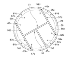
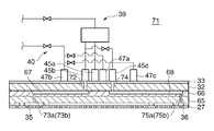
例えば、上述したシャワーヘッド13では、1つのガス分配板に1つのガス供給路が形成されたが、1つのガス分配板に2つのガス供給路が形成されてもよい。具体的には、シャワーヘッド71が、下から順に積層された対向板27、円板状部材からなる2つのガス分配板65,66、冷却板32及び蓋板33からなり、ガス分配板65には、ガス分配板28と同様に、中央ガス拡散室34、周縁ガス拡散室35及び最外ガス拡散室36が形成される。ガス分配板66には、図16や図18に示すように、蓋板33側の面(図18における上面)において、接続部45bを介して導入された処理ガスを周縁ガス拡散室35へ分配して供給するガス供給路67が形成されるとともに、接続部45cを介して導入された処理ガスを最外ガス拡散室36へ分配して供給するガス供給路68が形成される。また、ガス分配板65には、図17や図19に示すように、蓋板33側の面(図19における上面)において、接続部47bを介して導入された付加ガスを周縁ガス拡散室35へ分配して供給するガス供給路69が形成される。さらに、ガス分散板65には、接続部47cを介して導入された付加ガスを最外ガス拡散室36へ分配して供給するガス供給路70が形成される。なお、図16〜19では説明を簡単にするために一部の形状が省略される。
For example, in the
より、具体的には、周縁ガス拡散室35へ供給される処理ガスに関し、シャワーヘッド71では、接続部45bからガス供給路67の端部である連通箇所67aに連通する垂直ガス供給路72が形成される。また、ガス供給路67からガス分配板65,66を厚み方向に貫通して周縁ガス拡散室35(図16において破線で示す。)に開口する2つの垂直ガス供給路73a,73bが形成される。2つの垂直ガス供給路73a,73bは、周縁ガス拡散室35の中心に関して対称に配置され、且つ周方向に均等に配置される(図21参照。)。
More specifically, with respect to the processing gas supplied to the peripheral
ガス供給路67はガス分配板66の上面において連通箇所67aから各垂直ガス供給路73a,73bへ向けて各分岐路67b,67cに分岐し、各分岐路67b,67cの先端において各垂直ガス供給路73a,73bが開口する。シャワーヘッド71では、連通箇所67aから各分岐路67b,67cの先端までの距離が同一に設定され、垂直ガス供給路73a,73bの断面積は同一に設定され、且つ分岐路67b,67cの断面積も同一に設定されるため、接続部45bから各垂直ガス供給路73a,73bの周縁ガス拡散室35における開口部までのコンダクタンスは同一となる。
The
また、最外ガス拡散室36へ供給される処理ガスに関し、シャワーヘッド71では、接続部45cからガス供給路68の端部である連通箇所68aに連通する垂直ガス供給路74が形成される。また、ガス供給路68からガス分配板65,66を厚み方向に貫通して最外ガス拡散室36(図16において破線で示す。)に開口する2つの垂直ガス供給路75a,75bが形成される。2つの垂直ガス供給路75a,75bは、最外ガス拡散室36の中心に関して対称に配置され、且つ周方向に均等に配置される(図21参照。)。
Further, with respect to the processing gas supplied to the outermost
ガス供給路68はガス分配板66の上面において連通箇所68aから各垂直ガス供給路75a,75bへ向けて各分岐路68b,68cに分岐し、各分岐路68b,68cの先端において各垂直ガス供給路75a,75bが開口する。シャワーヘッド71では、連通箇所68aから各分岐路68b,68cの先端までの距離が同一に設定され、垂直ガス供給路75a,75bの断面積は同一に設定され、且つ分岐路68b,68cの断面積も同一に設定されるため、接続部45cから各垂直ガス供給路75a,75bの最外ガス拡散室36における開口部までのコンダクタンスは同一となる。
The
なお、図16において、ガス供給路67は平面視V字状に分岐し、ガス供給路68も平面視V字状に分岐するが、ガス供給路67,68の分岐形態はこれに限られず、連通箇所67aから各分岐路67b,67cの先端までの距離が同一であり、また、連通箇所68aから各分岐路68b,68cの先端までの距離が同一であれば、いずれの形態で形成されてもよい。
In FIG. 16, the
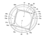
また、周縁ガス拡散室35へ供給される付加ガスに関し、シャワーヘッド71では、接続部47bからガス供給路69の端部である連通箇所69aに連通する垂直ガス供給路76が形成され、また、ガス供給路69からガス分配板65を厚み方向に貫通して周縁ガス拡散室35(図17において破線で示す。)に開口する2つの垂直ガス供給路77a,77bが形成される。2つの垂直ガス供給路77a,77bは、周縁ガス拡散室35の中心に関して対称に配置され、且つ周方向に均等に配置される(図21参照。)。ガス供給路69はガス分配板65の上面において連通箇所69aから各垂直ガス供給路77a,77bへ向けて各分岐路69b,69cに分岐し、各分岐路69b,69cの先端において各垂直ガス供給路77a,77bが開口する。シャワーヘッド71では、連通箇所69aから各分岐路69b,69cの先端までの距離が同一に設定される。また、垂直ガス供給路77a,77bの断面積は同一に設定され、且つ分岐路69b,69cの断面積も同一に設定される。その結果、接続部47bから各垂直ガス供給路77a,77bの周縁ガス拡散室35における開口部までのコンダクタンスは同一となる。
Further, with respect to the additional gas supplied to the peripheral
また、最外ガス拡散室36へ供給される付加ガスに関し、シャワーヘッド71では、接続部47cからガス供給路70の端部である連通箇所70aに連通する垂直ガス供給路78が形成される。また、ガス供給路70からガス分配板65を厚み方向に貫通して最外ガス拡散室36(図17において破線で示す。)に開口する2つの垂直ガス供給路79a,79bが形成される。2つの垂直ガス供給路79a,79bは、最外ガス拡散室36の中心に関して対称に配置され、且つ周方向に均等に配置される(図21参照。)。
Further, with respect to the additional gas supplied to the outermost
ガス供給路70はガス分配板65の上面において連通箇所70aから各垂直ガス供給路79a,79bへ向けて各分岐路70b,70cに分岐し、各分岐路70b,70cの先端において各垂直ガス供給路79a,79bが開口する。シャワーヘッド71では、連通箇所70aから各分岐路70b,70cの先端までの距離が同一に設定され、垂直ガス供給路79a,79bの断面積は同一に設定される。また、分岐路70b,70cの断面積も同一に設定される。したがって、接続部47cから各垂直ガス供給路79a,79bの最外ガス拡散室36における開口部までのコンダクタンスは同一となる。
The
なお、図17において、ガス供給路69は平面視V字状に分岐し、ガス供給路70も平面視V字状に分岐するが、ガス供給路69,70の分岐形態はこれに限られず、連通箇所69aから各分岐路69b,69cの先端までの距離が同一であり、また、連通箇所70aから各分岐路70b,70cの先端までの距離が同一であれば、いずれの形態で形成されてもよい。
In FIG. 17, the
シャワーヘッド71では、1つのガス分配板に2つのガス供給路が形成されるが、当該ガス分配板を複数積層することにより、図20に示すように、ガス分配板65,66、冷却板32及び蓋板33が積層されてガス供給路67〜70の配置箇所が平面視において重なった場合であっても、各ガス供給路67〜70同士の干渉等を考慮する必要がない。よって、ガス分配板を増やすことによってガス供給路を容易に増やすことができ、ガス拡散室の数を増やして処理空間Sをより数多くの領域に分割することができる。
In the
上述したシャワーヘッド13やシャワーヘッド71では、ガス分配板に形成されたガス供給路を用いて周縁ガス拡散室35や最外ガス拡散室36へ均等に処理ガスや付加ガスを供給することにより、周縁ガス拡散室35や最外ガス拡散室36において処理ガスや付加ガスを均等に分布させたが、上下に配置されて互いに連通する2つのガス拡散室を設けることにより、各ガス拡散室において処理ガスや付加ガスを均等に分布させてもよい。
In the
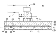
具体的には、図22や図23に示すように、シャワーヘッド80が、下から順に積層された対向板27、円板状部材からなる2つのガス分配板81,82、冷却板32及び蓋板33からなる。ガス分配板81には、ガス分配板28と同様に、中央ガス拡散室34、周縁ガス拡散室35及び最外ガス拡散室36が形成される。また、ガス分配板82にも、ガス分配板81と同様に、中央ガス拡散室34、周縁ガス拡散室35及び最外ガス拡散室36が形成される。
Specifically, as shown in FIGS. 22 and 23, the
ガス分配板81の中央ガス拡散室34(以下、「下の中央ガス拡散室34」という。)及びガス分配板82の中央ガス拡散室34(以下、「上の中央ガス拡散室34」という。)は、各中央ガス拡散室34の中心に関して対称に配置され、且つ周方向に均等に配置される複数の垂直ガス供給穴83によって連通する。また、ガス分配板81の周縁ガス拡散室35(以下、「下の周縁ガス拡散室35」という。)及びガス分配板82の周縁ガス拡散室35(以下、「上の周縁ガス拡散室35」という。)は、各周縁ガス拡散室35の中心に関して対称に配置され、且つ周方向に均等に配置される複数の垂直ガス供給穴84によって連通する。さらに、ガス分配板81の最外ガス拡散室36(以下、「下の最外ガス拡散室36」という。)及びガス分配板82の最外ガス拡散室36(以下、「上の最外ガス拡散室36」という。)は、各最外ガス拡散室36の中心に関して対称に配置され、且つ周方向に均等に配置される複数の垂直ガス供給穴85によって連通する。
The central
シャワーヘッド80では、上の中央ガス拡散室34に供給された処理ガスや付加ガスが自由拡散によって上の中央ガス拡散室34においてある程度均等に分布した後、周方向に均等に分布する垂直ガス供給穴83によって下の中央ガス拡散室34へ供給される。また、下の中央ガス拡散室34に供給された処理ガスや付加ガスはさらなる自由拡散によって下の中央ガス拡散室34において均等に分布する。上の周縁ガス拡散室35に供給された処理ガスや付加ガスが自由拡散によって上の周縁ガス拡散室35においてある程度均等に分布した後、周方向に均等に分布する垂直ガス供給穴84によって下の周縁ガス拡散室35へ供給される。また、下の周縁ガス拡散室35に供給された処理ガスや付加ガスはさらなる自由拡散によって下の周縁ガス拡散室35において均等に分布する。上の最外ガス拡散室36に供給された処理ガスや付加ガスが自由拡散によって上の最外ガス拡散室36においてある程度均等に分布した後、周方向に均等に分布する垂直ガス供給穴85によって下の最外ガス拡散室36へ供給される。また、下の最外ガス拡散室36に供給された処理ガスや付加ガスはさらなる自由拡散によって下の最外ガス拡散室36において均等に分布する。すなわち、シャワーヘッド80では、処理ガスや付加ガスが自由拡散を2回行うため、各ガス拡散室(下の中央ガス拡散室34、下の周縁ガス拡散室35、下の最外ガス拡散室36)において処理ガスや付加ガスを均等に分布させることができる。
In the
S 処理空間
W ウエハ
10 基板処理装置
11 チャンバ
13,71,80 シャワーヘッド
28〜31,65,66,81,82 ガス分配板
34 中央ガス拡散室
35 周縁ガス拡散室
36 最外ガス拡散室
39 処理ガス導入系
40 付加ガス導入系
52〜55,67〜70 ガス供給路
S Processing
Claims (5)
前記処理空間に対向し且つ多数の貫通穴を有する対向板と、複数のガス分配板と、蓋板とを備え、
前記対向板、前記複数のガス分配板、及び蓋板がこの順で積層され、
最も前記対向板寄りの前記ガス分配板における前記対向板側の面には複数のガス拡散室が形成され、
前記ガス分配板の各々には、前記処理ガス供給源から前記複数のガス拡散室の各々へ個別に前記処理ガスを供給するガス供給路、又は、前記付加ガス供給源から前記複数のガス拡散室の各々へ個別に前記付加ガスを供給する他のガス供給路が形成され、
前記処理ガス供給源及び前記複数のガス拡散室の各々は、1つの前記処理ガス供給路のみで接続され、前記付加ガス供給源及び前記複数のガス拡散室の各々は、1つの前記他のガス供給路のみで接続され、
前記ガス分配板の各々において、前記ガス供給路は複数の分岐路に分岐し、前記処理ガス供給源から各前記分岐路の先端までの距離は同一であり、又は、前記他のガス供給路は複数の他の分岐路に分岐し、前記付加ガス供給源から各前記他の分岐路の先端までの距離は同一であることを特徴とするガス供給装置。 A gas supply device that supplies a processing gas from a processing gas supply source to a processing space and supplies an additional gas from the additional gas supply source to the processing space,
A counter plate facing the processing space and having a plurality of through holes, a plurality of gas distribution plates, and a cover plate;
The counter plate, the plurality of gas distribution plates, and the cover plate are laminated in this order,
A plurality of gas diffusion chambers are formed on the surface on the counter plate side of the gas distribution plate closest to the counter plate,
In each of the gas distribution plates, a gas supply path for individually supplying the processing gas from the processing gas supply source to each of the plurality of gas diffusion chambers, or a plurality of gas diffusion chambers from the additional gas supply source Other gas supply paths for supplying the additional gas individually to each of
Each of the processing gas supply source and the plurality of gas diffusion chambers is connected by only one processing gas supply path, and each of the additional gas supply source and the plurality of gas diffusion chambers is one other gas. Connected only through the supply path,
In each of the gas distribution plates, the gas supply path branches into a plurality of branch paths, and the distance from the processing gas supply source to the tip of each branch path is the same, or the other gas supply paths are A gas supply device that branches into a plurality of other branch paths and that has the same distance from the additional gas supply source to the tip of each of the other branch paths.
前記複数のガス拡散室は複数の溝状空間を含み、
前記複数の溝状空間は前記基板の外縁よりも外側に対向するように形成されることを特徴とする請求項1又は2記載のガス供給装置。 The gas supply device faces a disk-shaped substrate through the processing space,
The plurality of gas diffusion chambers include a plurality of groove-like spaces,
3. The gas supply device according to claim 1, wherein the plurality of groove-like spaces are formed so as to face the outer side of the outer edge of the substrate.
前記ガス供給装置は、前記処理空間に対向し且つ多数の貫通穴を有する対向板と、複数のガス分配板と、蓋板とを有し、
前記対向板、前記複数のガス分配板、及び蓋板がこの順で積層され、
最も前記対向板寄りの前記ガス分配板における前記対向板側の面には複数のガス拡散室が形成され、
前記ガス分配板の各々には、前記処理ガス供給源から前記複数のガス拡散室の各々へ個別に前記処理ガスを供給するガス供給路、又は、前記付加ガス供給源から前記複数のガス拡散室の各々へ個別に前記付加ガスを供給する他のガス供給路が形成され、
前記処理ガス供給源及び前記複数のガス拡散室の各々は、1つの前記処理ガス供給路のみで接続され、前記付加ガス供給源及び前記複数のガス拡散室の各々は、1つの前記他のガス供給路のみで接続され、
前記ガス分配板の各々において、前記ガス供給路は複数の分岐路に分岐し、前記処理ガス供給源から各前記分岐路の先端までの距離は同一であり、又は、前記他のガス供給路は複数の他の分岐路に分岐し、前記付加ガス供給源から各前記他の分岐路の先端までの距離は同一であることを特徴とする基板処理装置。 A processing chamber that accommodates the substrate in the processing space, and is disposed so as to face the substrate, supplies processing gas from the processing gas supply source to the processing space, and supplies additional gas from the additional gas supply source to the processing space. A substrate processing apparatus comprising: a gas supply device that performs:
The gas supply device includes a counter plate facing the processing space and having a plurality of through holes, a plurality of gas distribution plates, and a cover plate,
The counter plate, the plurality of gas distribution plates, and the cover plate are laminated in this order,
A plurality of gas diffusion chambers are formed on the surface on the counter plate side of the gas distribution plate closest to the counter plate,
In each of the gas distribution plates, a gas supply path for individually supplying the processing gas from the processing gas supply source to each of the plurality of gas diffusion chambers, or a plurality of gas diffusion chambers from the additional gas supply source Other gas supply paths for supplying the additional gas individually to each of
Each of the processing gas supply source and the plurality of gas diffusion chambers is connected by only one processing gas supply path, and each of the additional gas supply source and the plurality of gas diffusion chambers is one other gas. Connected only through the supply path,
In each of the gas distribution plates, the gas supply path branches into a plurality of branch paths, and the distance from the processing gas supply source to the tip of each branch path is the same, or the other gas supply paths are A substrate processing apparatus that branches into a plurality of other branch paths and that has the same distance from the additional gas supply source to the tip of each of the other branch paths.
Priority Applications (7)
| Application Number | Priority Date | Filing Date | Title |
|---|---|---|---|
| JP2012109798A JP6157061B2 (en) | 2012-05-11 | 2012-05-11 | Gas supply apparatus and substrate processing apparatus |
| US14/391,482 US9887108B2 (en) | 2012-05-11 | 2013-05-09 | Gas supply device and substrate processing apparatus |
| CN201380019330.9A CN104205309B (en) | 2012-05-11 | 2013-05-09 | Gas supply device and substrate board treatment |
| PCT/JP2013/063616 WO2013168825A1 (en) | 2012-05-11 | 2013-05-09 | Gas supply device and substrate processing device |
| KR1020147028375A KR102070702B1 (en) | 2012-05-11 | 2013-05-09 | Gas supply device and substrate processing device |
| TW102116612A TWI611039B (en) | 2012-05-11 | 2013-05-10 | Gas supply device and substrate processing device |
| US15/852,194 US10199241B2 (en) | 2012-05-11 | 2017-12-22 | Gas supply device and substrate processing apparatus |
Applications Claiming Priority (1)
| Application Number | Priority Date | Filing Date | Title |
|---|---|---|---|
| JP2012109798A JP6157061B2 (en) | 2012-05-11 | 2012-05-11 | Gas supply apparatus and substrate processing apparatus |
Publications (3)
| Publication Number | Publication Date |
|---|---|
| JP2013239482A JP2013239482A (en) | 2013-11-28 |
| JP2013239482A5 JP2013239482A5 (en) | 2015-06-25 |
| JP6157061B2 true JP6157061B2 (en) | 2017-07-05 |
Family
ID=49550852
Family Applications (1)
| Application Number | Title | Priority Date | Filing Date |
|---|---|---|---|
| JP2012109798A Active JP6157061B2 (en) | 2012-05-11 | 2012-05-11 | Gas supply apparatus and substrate processing apparatus |
Country Status (6)
| Country | Link |
|---|---|
| US (2) | US9887108B2 (en) |
| JP (1) | JP6157061B2 (en) |
| KR (1) | KR102070702B1 (en) |
| CN (1) | CN104205309B (en) |
| TW (1) | TWI611039B (en) |
| WO (1) | WO2013168825A1 (en) |
Families Citing this family (25)
| Publication number | Priority date | Publication date | Assignee | Title |
|---|---|---|---|---|
| US8562785B2 (en) * | 2011-05-31 | 2013-10-22 | Lam Research Corporation | Gas distribution showerhead for inductively coupled plasma etch reactor |
| US9245717B2 (en) | 2011-05-31 | 2016-01-26 | Lam Research Corporation | Gas distribution system for ceramic showerhead of plasma etch reactor |
| JP6157061B2 (en) * | 2012-05-11 | 2017-07-05 | 東京エレクトロン株式会社 | Gas supply apparatus and substrate processing apparatus |
| JP6007143B2 (en) * | 2013-03-26 | 2016-10-12 | 東京エレクトロン株式会社 | Shower head, plasma processing apparatus, and plasma processing method |
| JP6169040B2 (en) * | 2014-05-12 | 2017-07-26 | 東京エレクトロン株式会社 | Upper electrode structure of plasma processing apparatus, plasma processing apparatus, and method of operating plasma processing apparatus |
| JP2016225018A (en) * | 2015-05-27 | 2016-12-28 | 東京エレクトロン株式会社 | Gas processing device and multi-division shower head used for the same |
| TWI723024B (en) * | 2015-06-26 | 2021-04-01 | 美商應用材料股份有限公司 | Recursive inject apparatus for improved distribution of gas |
| US20170002465A1 (en) * | 2015-06-30 | 2017-01-05 | Lam Research Corporation | Separation of Plasma Suppression and Wafer Edge to Improve Edge Film Thickness Uniformity |
| WO2017117221A1 (en) * | 2016-01-01 | 2017-07-06 | Applied Materials, Inc. | Non-metallic thermal cvd/ald gas injector and purge system |
| JP6696322B2 (en) * | 2016-06-24 | 2020-05-20 | 東京エレクトロン株式会社 | Gas processing apparatus, gas processing method and storage medium |
| CN106498367B (en) * | 2016-10-21 | 2018-09-14 | 哈尔滨工业大学 | A kind of compact type vacuum reaction unit for chemical vapor deposition diamond film |
| JP6851188B2 (en) * | 2016-11-28 | 2021-03-31 | 東京エレクトロン株式会社 | Plasma processing equipment and shower head |
| CN106783500A (en) * | 2017-01-03 | 2017-05-31 | 京东方科技集团股份有限公司 | Filming equipment |
| KR102493945B1 (en) * | 2017-06-06 | 2023-01-30 | 어플라이드 머티어리얼스, 인코포레이티드 | Deposition radial and edge profile tenability through independent control of teos flow |
| US20190119815A1 (en) * | 2017-10-24 | 2019-04-25 | Applied Materials, Inc. | Systems and processes for plasma filtering |
| US10541361B2 (en) | 2017-11-30 | 2020-01-21 | Taiwan Semiconductor Manufacturing Co., Ltd. | Magnetic random access memory and manufacturing method thereof |
| US10903054B2 (en) | 2017-12-19 | 2021-01-26 | Applied Materials, Inc. | Multi-zone gas distribution systems and methods |
| KR102576220B1 (en) * | 2018-06-22 | 2023-09-07 | 삼성디스플레이 주식회사 | Thin Film Processing Appartus and Method |
| KR102641752B1 (en) * | 2018-11-21 | 2024-03-04 | 삼성전자주식회사 | Gas injection module, substrate processing apparatus and method for manufacturing semiconductor device using the same |
| US11367594B2 (en) * | 2019-11-27 | 2022-06-21 | Applied Materials, Inc. | Multizone flow gasbox for processing chamber |
| US12011731B2 (en) * | 2020-07-10 | 2024-06-18 | Applied Materials, Inc. | Faceplate tensioning method and apparatus to prevent droop |
| US20220044917A1 (en) * | 2020-08-07 | 2022-02-10 | Semes Co., Ltd. | Substrate treating apparatus and substrate support unit |
| US20220199373A1 (en) * | 2020-12-18 | 2022-06-23 | Applied Materials, Inc. | Methods to eliminate of deposition on wafer bevel and backside |
| GB2610156A (en) * | 2021-04-29 | 2023-03-01 | Edwards Ltd | Semiconductor processing system |
| CN116130325A (en) * | 2021-11-12 | 2023-05-16 | 中微半导体设备(上海)股份有限公司 | Mounting base, spray header assembly, temperature control method and plasma processing device |
Family Cites Families (27)
| Publication number | Priority date | Publication date | Assignee | Title |
|---|---|---|---|---|
| US4537217A (en) * | 1982-12-09 | 1985-08-27 | Research Triangle Institute | Fluid distributor |
| JP3380091B2 (en) * | 1995-06-09 | 2003-02-24 | 株式会社荏原製作所 | Reactive gas injection head and thin film vapor phase growth apparatus |
| JPH0945624A (en) * | 1995-07-27 | 1997-02-14 | Tokyo Electron Ltd | Leaf-type heat treating system |
| JP3501930B2 (en) * | 1997-12-01 | 2004-03-02 | 株式会社ルネサステクノロジ | Plasma processing method |
| US6333019B1 (en) * | 1999-04-29 | 2001-12-25 | Marc-Olivier Coppens | Method for operating a chemical and/or physical process by means of a hierarchical fluid injection system |
| AU2976901A (en) * | 2000-01-27 | 2001-08-07 | Amalgamated Res Inc | Shallow bed fluid treatment apparatus |
| KR100516844B1 (en) * | 2001-01-22 | 2005-09-26 | 동경 엘렉트론 주식회사 | Device and method for treatment |
| JP4545330B2 (en) * | 2001-02-22 | 2010-09-15 | イビデン株式会社 | Gas ejection plate of plasma etching equipment |
| GB0111485D0 (en) * | 2001-05-11 | 2001-07-04 | Amersham Pharm Biotech Ab | Scalable liquid distribution system for large scale chromatography columns |
| ES2378144T3 (en) * | 2001-05-17 | 2012-04-09 | Amalgamated Research, Inc. | Fractal device for mixing and reactor applications |
| FI113527B (en) * | 2002-12-31 | 2004-05-14 | Raute Oyj | Nozzle unit for spreading foamed glue, has distribution canal network including compensation canal closed to external forming free flow channel between branches of distribution canal network |
| US20070299292A1 (en) * | 2006-06-23 | 2007-12-27 | Catalytic Distillation Technologies | Paraffin alkylation |
| US20080081114A1 (en) * | 2006-10-03 | 2008-04-03 | Novellus Systems, Inc. | Apparatus and method for delivering uniform fluid flow in a chemical deposition system |
| US20080099147A1 (en) * | 2006-10-26 | 2008-05-01 | Nyi Oo Myo | Temperature controlled multi-gas distribution assembly |
| JP2008117477A (en) | 2006-11-06 | 2008-05-22 | Pioneer Electronic Corp | Recording medium holding device, and disk device |
| US7674394B2 (en) | 2007-02-26 | 2010-03-09 | Applied Materials, Inc. | Plasma process for inductively coupling power through a gas distribution plate while adjusting plasma distribution |
| DE502007001071D1 (en) * | 2007-03-05 | 2009-08-27 | Re | Coating plant and gas pipeline system |
| JP5192214B2 (en) * | 2007-11-02 | 2013-05-08 | 東京エレクトロン株式会社 | Gas supply apparatus, substrate processing apparatus, and substrate processing method |
| US20090133631A1 (en) * | 2007-11-23 | 2009-05-28 | Applied Materials Inc. | Coating device and method of producing an electrode assembly |
| US20090159213A1 (en) * | 2007-12-19 | 2009-06-25 | Applied Materials, Inc. | Plasma reactor gas distribution plate having a path splitting manifold immersed within a showerhead |
| US8512509B2 (en) * | 2007-12-19 | 2013-08-20 | Applied Materials, Inc. | Plasma reactor gas distribution plate with radially distributed path splitting manifold |
| US20090275206A1 (en) * | 2008-05-05 | 2009-11-05 | Applied Materials, Inc. | Plasma process employing multiple zone gas distribution for improved uniformity of critical dimension bias |
| WO2010101369A2 (en) * | 2009-03-03 | 2010-09-10 | 주성엔지니어링㈜ | Gas distribution apparatus, and substrate-processing apparatus comprising same |
| KR101108879B1 (en) * | 2009-08-31 | 2012-01-30 | 주식회사 원익아이피에스 | Gas injecting device and Substrate processing apparatus using the same |
| US20110308458A1 (en) * | 2010-06-21 | 2011-12-22 | Semes Co., Ltd. | Thin Film Deposition Apparatus |
| JP5792563B2 (en) * | 2011-08-31 | 2015-10-14 | 東京エレクトロン株式会社 | Plasma etching method and plasma etching apparatus |
| JP6157061B2 (en) * | 2012-05-11 | 2017-07-05 | 東京エレクトロン株式会社 | Gas supply apparatus and substrate processing apparatus |
-
2012
- 2012-05-11 JP JP2012109798A patent/JP6157061B2/en active Active
-
2013
- 2013-05-09 CN CN201380019330.9A patent/CN104205309B/en active Active
- 2013-05-09 US US14/391,482 patent/US9887108B2/en active Active
- 2013-05-09 WO PCT/JP2013/063616 patent/WO2013168825A1/en active Application Filing
- 2013-05-09 KR KR1020147028375A patent/KR102070702B1/en active IP Right Grant
- 2013-05-10 TW TW102116612A patent/TWI611039B/en active
-
2017
- 2017-12-22 US US15/852,194 patent/US10199241B2/en active Active
Also Published As
| Publication number | Publication date |
|---|---|
| CN104205309B (en) | 2016-10-19 |
| US20150107772A1 (en) | 2015-04-23 |
| US10199241B2 (en) | 2019-02-05 |
| CN104205309A (en) | 2014-12-10 |
| WO2013168825A1 (en) | 2013-11-14 |
| JP2013239482A (en) | 2013-11-28 |
| TW201408812A (en) | 2014-03-01 |
| KR102070702B1 (en) | 2020-01-29 |
| US9887108B2 (en) | 2018-02-06 |
| KR20150018773A (en) | 2015-02-24 |
| US20180190519A1 (en) | 2018-07-05 |
| TWI611039B (en) | 2018-01-11 |
Similar Documents
| Publication | Publication Date | Title |
|---|---|---|
| JP6157061B2 (en) | Gas supply apparatus and substrate processing apparatus | |
| TWI713452B (en) | Substrate support with more uniform edge purge | |
| US11139150B2 (en) | Nozzle for multi-zone gas injection assembly | |
| TWI618141B (en) | Chemical control features in wafer process equipment | |
| JP5913312B2 (en) | Semiconductor wafer processing apparatus, semiconductor wafer processing system, and gas distribution unit for neutral / ion flux control | |
| CN104838476B (en) | For providing plasma to the device of processing chamber housing | |
| TWI615499B (en) | Tunable gas delivery assembly with internal diffuser and angular injection | |
| TW201411717A (en) | Proportional and uniform controlled gas flow delivery for dry plasma etch apparatus | |
| JP4142545B2 (en) | Gas supply device | |
| JP2016063221A5 (en) | ||
| JP2013541177A5 (en) | Semiconductor wafer processing apparatus, semiconductor wafer processing system, and gas distribution unit for neutral / ion flux control | |
| JP2013084602A5 (en) | ||
| TWI661462B (en) | Plasma processing device and gas supply member | |
| KR20060059305A (en) | Semiconductor processing equipment | |
| US11944988B2 (en) | Multi-zone showerhead | |
| CN110391124A (en) | Spray head and substrate-treating apparatus | |
| JP2024523698A (en) | Showerhead assembly having recursive gas channels - Patents.com | |
| CN116057664A (en) | Showerhead assembly with recursive gas passages |
Legal Events
| Date | Code | Title | Description |
|---|---|---|---|
| A521 | Request for written amendment filed |
Free format text: JAPANESE INTERMEDIATE CODE: A523 Effective date: 20150508 |
|
| A621 | Written request for application examination |
Free format text: JAPANESE INTERMEDIATE CODE: A621 Effective date: 20150508 |
|
| A131 | Notification of reasons for refusal |
Free format text: JAPANESE INTERMEDIATE CODE: A131 Effective date: 20160705 |
|
| A521 | Request for written amendment filed |
Free format text: JAPANESE INTERMEDIATE CODE: A523 Effective date: 20160829 |
|
| A131 | Notification of reasons for refusal |
Free format text: JAPANESE INTERMEDIATE CODE: A131 Effective date: 20161206 |
|
| A521 | Request for written amendment filed |
Free format text: JAPANESE INTERMEDIATE CODE: A523 Effective date: 20170123 |
|
| A521 | Request for written amendment filed |
Free format text: JAPANESE INTERMEDIATE CODE: A523 Effective date: 20170130 |
|
| TRDD | Decision of grant or rejection written | ||
| A01 | Written decision to grant a patent or to grant a registration (utility model) |
Free format text: JAPANESE INTERMEDIATE CODE: A01 Effective date: 20170523 |
|
| A61 | First payment of annual fees (during grant procedure) |
Free format text: JAPANESE INTERMEDIATE CODE: A61 Effective date: 20170606 |
|
| R150 | Certificate of patent or registration of utility model |
Ref document number: 6157061 Country of ref document: JP Free format text: JAPANESE INTERMEDIATE CODE: R150 |
|
| R250 | Receipt of annual fees |
Free format text: JAPANESE INTERMEDIATE CODE: R250 |
|
| R250 | Receipt of annual fees |
Free format text: JAPANESE INTERMEDIATE CODE: R250 |
|
| R250 | Receipt of annual fees |
Free format text: JAPANESE INTERMEDIATE CODE: R250 |
|
| R250 | Receipt of annual fees |
Free format text: JAPANESE INTERMEDIATE CODE: R250 |
|
| R250 | Receipt of annual fees |
Free format text: JAPANESE INTERMEDIATE CODE: R250 |