JP6150933B2 - Through-hole measure unit and through-hole measure structure - Google Patents

Through-hole measure unit and through-hole measure structure Download PDF

Info

Publication number
JP6150933B2
JP6150933B2 JP2016192785A JP2016192785A JP6150933B2 JP 6150933 B2 JP6150933 B2 JP 6150933B2 JP 2016192785 A JP2016192785 A JP 2016192785A JP 2016192785 A JP2016192785 A JP 2016192785A JP 6150933 B2 JP6150933 B2 JP 6150933B2
Authority
JP
Japan
Prior art keywords
hole
sleeve member
integrated
sleeve
fireproof
Prior art date
Legal status (The legal status is an assumption and is not a legal conclusion. Google has not performed a legal analysis and makes no representation as to the accuracy of the status listed.)
Active
Application number
JP2016192785A
Other languages
Japanese (ja)
Other versions
JP2017070199A (en
Inventor
古賀 誠一
誠一 古賀
翔太 勝部
翔太 勝部
Current Assignee (The listed assignees may be inaccurate. Google has not performed a legal analysis and makes no representation or warranty as to the accuracy of the list.)
Inaba Denki Sangyo Co Ltd
Original Assignee
Inaba Denki Sangyo Co Ltd
Priority date (The priority date is an assumption and is not a legal conclusion. Google has not performed a legal analysis and makes no representation as to the accuracy of the date listed.)
Filing date
Publication date
Application filed by Inaba Denki Sangyo Co Ltd filed Critical Inaba Denki Sangyo Co Ltd
Publication of JP2017070199A publication Critical patent/JP2017070199A/en
Application granted granted Critical
Publication of JP6150933B2 publication Critical patent/JP6150933B2/en
Active legal-status Critical Current
Anticipated expiration legal-status Critical

Links

Images

Landscapes

  • Building Environments (AREA)
  • Installation Of Indoor Wiring (AREA)
  • Electric Cable Installation (AREA)

Description

本発明は、貫通孔措置ユニット及び貫通孔措置構造に関する。   The present invention relates to a through-hole measure unit and a through-hole measure structure.

一般に、建築物の内部空間は壁・床・天井等の区画体によって複数の室空間に区画されている。これら複数の室空間に亘って例えば配管やケーブル等の長尺体を配設するため、区画体に貫通孔を形成して当該貫通孔に長尺体を挿通させる場合がある。この場合、その貫通孔と長尺体との間の隙間を充填材で埋める等の後処理が必要となる。例えば、ある室空間において火災が発生した場合における延焼を防止するためには、貫通孔と長尺体との間の隙間に防火措置を施す必要がある。   Generally, the internal space of a building is partitioned into a plurality of room spaces by partitions such as walls, floors, and ceilings. In order to arrange a long body such as a pipe or a cable over the plurality of chamber spaces, for example, a through hole may be formed in the partition body and the long body may be inserted through the through hole. In this case, post-processing such as filling the gap between the through hole and the elongated body with a filler is necessary. For example, in order to prevent the spread of fire when a fire occurs in a certain room space, it is necessary to take fire prevention measures in the gap between the through hole and the elongated body.

例えば特開2005−73357号公報(特許文献1)には、袋体の内部に密封されたペースト状の熱膨張性耐火材を含むパック部材を閉塞部材として用いた防火措置構造が開示されている。閉塞部材(パック部材)は、区画体の貫通孔に設置された受け具の開口側で、長尺体の周囲に巻き付けられて、その後、貫通孔(受け具)に押し込まれる。そして、閉塞部材は、受け具に保持された状態で貫通孔の内面と長尺体の外面との間に生じる隙間を埋める。ここで、特許文献1の閉塞部材は、袋体の内面が全面で高稠度の熱膨張性耐火材と密着しており、そのままで自由自在に変形できるようになっている。   For example, Japanese Patent Laying-Open No. 2005-73357 (Patent Document 1) discloses a fire protection structure using a pack member including a paste-like thermally expandable refractory material sealed inside a bag as a closing member. . The closing member (pack member) is wound around the elongated body on the opening side of the receiving device installed in the through hole of the partition body, and then pushed into the through hole (receiving device). Then, the closing member fills a gap generated between the inner surface of the through hole and the outer surface of the elongated body while being held by the receiver. Here, the closing member of Patent Document 1 has the inner surface of the bag body in close contact with the highly-consistent, heat-expandable refractory material, and can be freely deformed as it is.

特許文献1の閉塞部材は、変形自在な柔軟性を有しているので、凹凸のある曲面にもなじみやすいという利点があるものの、区画体の貫通孔への押込操作が容易でないという欠点があった。特に、長尺体の外面と貫通孔又は受け具の内面との間の隙間が狭い場合には、摺動抵抗が相対的に大きくなる一方で閉塞部材を押し込む際の押圧力が分散されるため、かかる押込操作に大きく手間取る場合があった。   Since the closure member of Patent Document 1 has flexibility that can be deformed, there is an advantage that it is easy to adapt to a curved surface with unevenness, but there is a disadvantage that the pushing operation to the through hole of the partition is not easy. It was. In particular, when the gap between the outer surface of the elongated body and the inner surface of the through hole or the receiver is narrow, the sliding force is relatively increased while the pressing force when pushing the closing member is dispersed. In some cases, this push-in operation takes time and effort.

特開2005−73357号公報JP 2005-73357 A

区画体の貫通孔に対して後処理を施す際の施工性に優れ、且つ、凹凸のある曲面部分によって形成される空間をも含めて貫通孔と長尺体との間の隙間を十分に埋めることのできる技術が求められている。   Excellent workability when performing post-processing on the through-holes of the partition body, and sufficiently fills the gap between the through-holes and the long body including the space formed by the curved surface part with unevenness. There is a need for technology that can.

本発明に係る貫通孔措置ユニットは、
建築物の区画体に形成された貫通孔に挿入される筒状のスリーブ部材と、
柔軟性を有する閉塞部材と、を備え、
前記閉塞部材が前記スリーブ部材に対して周方向に沿って重ねて配置されているとともに、前記スリーブ部材の軸方向の一端にて前記スリーブ部材と前記閉塞部材とが一体化されている。
The through hole measure unit according to the present invention is:
A cylindrical sleeve member inserted into a through-hole formed in a partition of a building;
A closure member having flexibility,
The closing member is disposed so as to overlap the sleeve member along the circumferential direction, and the sleeve member and the closing member are integrated at one end in the axial direction of the sleeve member.

この構成によれば、閉塞部材がスリーブ部材の内面に沿って筒状をなす状態で、区画体の貫通孔に対して、スリーブ部材と閉塞部材とを一体的に挿入することができる。閉塞部材が柔軟性を有して柔らかい場合であっても、ある程度の剛性を有するスリーブ部材と共に、閉塞部材を貫通孔の奥まで容易に挿入することができる。貫通孔内に挿入された後は、閉塞部材におけるスリーブ部材と一体化されていない部分(以下、「非一体化部分」と言う。)を容易に変形させて、凹凸のある曲面によって形成される空間を非一体化部分で埋めることができる。従って、本構成の貫通孔措置ユニットを用いることで、区画体の貫通孔に対して後処理を施す際の施工性を向上させることができるとともに、凹凸のある曲面部分によって形成される空間をも含めて貫通孔と長尺体との間の隙間を十分に埋めることができる。   According to this configuration, the sleeve member and the closing member can be integrally inserted into the through hole of the partition body in a state where the closing member forms a cylinder shape along the inner surface of the sleeve member. Even when the closing member is flexible and soft, the closing member can be easily inserted into the through hole together with the sleeve member having a certain degree of rigidity. After being inserted into the through-hole, a portion of the closing member that is not integrated with the sleeve member (hereinafter referred to as “non-integrated portion”) is easily deformed to form an uneven curved surface. The space can be filled with non-integrated parts. Therefore, by using the through-hole measure unit of this configuration, it is possible to improve the workability when performing post-processing on the through-holes of the partition body, and also to provide a space formed by uneven curved surface portions. Including the gap between the through hole and the elongated body can be sufficiently filled.

以下、本発明に係る貫通孔措置ユニットの好適な態様について説明する。但し、以下に記載する好適な態様例によって、本発明の範囲が限定される訳ではない。   Hereinafter, the suitable aspect of the through-hole measure unit which concerns on this invention is demonstrated. However, the scope of the present invention is not limited by the preferred embodiments described below.

1つの態様として、前記閉塞部材の周方向の長さが前記スリーブ部材の周方向の長さよりも長く、前記閉塞部材の周方向の両端部が互いに重複可能となっていると好適である。   As one aspect, it is preferable that the length in the circumferential direction of the closing member is longer than the length in the circumferential direction of the sleeve member, and both end portions in the circumferential direction of the closing member can overlap each other.

この構成によれば、スリーブ部材の内面に沿って閉塞部材を筒状とした際に、閉塞部材の周方向の両端部を互いに重複させることができる。よって、閉塞部材の非一体化部分を変形させた際にも、閉塞部材を全周に亘って途切れることなく配置することが容易である。また、閉塞部材が互いに重複した周方向の部分は、他の部分に比べて閉塞部材の量が多くなる。このため、当該重複部位を例えば凹凸のある曲面によって形成される複数の空間のうち相対的に大きな空間に配置することで、貫通孔と長尺体との間の隙間を十分に且つ効果的に埋めることができる。   According to this configuration, when the closing member is cylindrical along the inner surface of the sleeve member, both end portions in the circumferential direction of the closing member can overlap each other. Therefore, even when the non-integrated portion of the closing member is deformed, it is easy to dispose the closing member without interruption over the entire circumference. In addition, the circumferential portion where the closing members overlap each other has a larger amount of the closing member than the other portions. For this reason, by arranging the overlapping portion in a relatively large space among a plurality of spaces formed by, for example, an uneven curved surface, the gap between the through hole and the elongated body can be sufficiently and effectively obtained. Can be filled.

1つの態様として、前記スリーブ部材が、軸方向における前記閉塞部材と一体化されている方の一体化端部の外面に、当該一体化端部の端縁側に向かうに従って次第に縮径するテーパー面を有すると好適である。   As one aspect, a taper surface that gradually decreases in diameter toward the end edge side of the integrated end portion on the outer surface of the integrated end portion of the sleeve member that is integrated with the closing member in the axial direction. It is suitable to have.

この構成によれば、スリーブ部材の一体化端部の外面に形成されるテーパー面が、閉塞部材と一体化されたスリーブ部材を区画体の貫通孔に挿入する際に案内作用を発揮する。よって、区画体の貫通孔に対して、スリーブ部材及び閉塞部材を容易に挿入することができ、この点からも施工性を向上させることができる。   According to this configuration, the tapered surface formed on the outer surface of the integrated end portion of the sleeve member exhibits a guiding action when the sleeve member integrated with the closing member is inserted into the through hole of the partitioning body. Therefore, the sleeve member and the closing member can be easily inserted into the through hole of the partition body, and the workability can be improved from this point.

1つの態様として、前記閉塞部材の軸方向の長さが前記スリーブ部材の軸方向の長さよりも長く、前記閉塞部材における前記スリーブ部材と一体化されていない方の開放側端部が、前記スリーブ部材における前記閉塞部材と一体化されていない方の開放側端部から突出していると好適である。   As one aspect, the length of the closing member in the axial direction is longer than the length of the sleeve member in the axial direction, and the opening-side end portion of the closing member that is not integrated with the sleeve member is the sleeve. It is preferable that the member protrudes from the open side end portion that is not integrated with the closing member.

この構成によれば、閉塞部材の容積を一定量確保しつつ、閉塞部材の薄型化を図ることができる。よって、長尺体の外面と貫通孔の内面との間の隙間が狭い場合であっても、当該隙間に、スリーブ部材と共に閉塞部材を容易に挿入することができる。   According to this configuration, it is possible to reduce the thickness of the closing member while securing a certain amount of the closing member. Therefore, even when the gap between the outer surface of the elongated body and the inner surface of the through hole is narrow, the closing member can be easily inserted into the gap together with the sleeve member.

1つの態様として、前記スリーブ部材に対して当該スリーブ部材の前記開放側端部側から内挿されるガイド部材をさらに備え、前記閉塞部材の前記開放側端部にて前記ガイド部材と前記閉塞部材とが一体化されていると好適である。   As one aspect, the apparatus further comprises a guide member inserted from the open side end portion side of the sleeve member with respect to the sleeve member, and the guide member and the close member at the open side end portion of the close member Are preferably integrated.

この構成によれば、貫通孔内にスリーブ部材と共に閉塞部材を一端側から挿入した後、スリーブ部材の開放側端部から突出して未挿入となっている閉塞部材の開放側端部を、ガイド部材と共に容易にスリーブ部材の内側空間に挿入することができる。ガイド部材を押込操作するだけで、閉塞部材の開放側端部を直接的に操作することなく、凹凸のある曲面によって形成される空間を容易に埋めることができる。   According to this configuration, after the closing member is inserted into the through hole from the one end side together with the sleeve member, the opening side end portion of the closing member protruding from the opening side end portion of the sleeve member and not inserted is guided to the guide member. At the same time, it can be easily inserted into the inner space of the sleeve member. By simply pushing the guide member, the space formed by the curved surface with unevenness can be easily filled without directly operating the open end of the closing member.

1つの態様として、前記閉塞部材が、柔軟性を有する袋体と当該袋体の内部に封入されたペースト状の充填材とを含むパック部材であると好適である。   As one aspect, it is preferable that the closing member is a pack member including a flexible bag and a paste-like filler enclosed in the bag.

この構成によれば、袋体が柔軟性を有するとともに充填材がペースト状であるので、閉塞部材としてのパック部材に、変形自在な柔軟性を付与することができる。よって、凹凸のある曲面にもなじみやすく、貫通孔と長尺体との間の隙間をより確実に埋めることができる。しかも、上述したようにスリーブ部材と共にパック部材を貫通孔の奥まで容易に挿入することができるので、施工性も良好である。充填材が袋体の内部に封入されているので、作業者がペースト状の充填材に直接触れることがなく、作業者に不快感を与えることもない。   According to this configuration, since the bag body has flexibility and the filling material is in a paste form, the flexible flexibility can be imparted to the pack member as the closing member. Therefore, it is easy to adapt to a curved surface with unevenness, and the gap between the through hole and the elongated body can be filled more reliably. In addition, since the pack member can be easily inserted into the through hole together with the sleeve member as described above, the workability is also good. Since the filler is enclosed in the bag body, the operator does not directly touch the paste-like filler, and the operator does not feel uncomfortable.

1つの態様として、前記閉塞部材が、可撓性を有するシート状部材であると好適である。   As one aspect, it is preferable that the closing member is a flexible sheet-like member.

この構成によれば、閉塞部材としてのシート状部材が可撓性を有するシート状であるので、凹凸のある曲面に巻きやすく、貫通孔と長尺体との間の隙間を埋める際の施工性を向上させることができる。また、たわめることができる程度に柔軟で、ある程度の定形性を有するシート状部材であれば、重力等の作用を受けて下方に偏ってしまうことを抑制できる。よって、施工後も長期間に亘って、貫通孔と長尺体との間の隙間にシート状部材を均一に配置することができる。   According to this configuration, since the sheet-like member as the closing member is a flexible sheet-like member, it is easy to wind around an uneven curved surface, and workability when filling the gap between the through hole and the elongated body Can be improved. Moreover, if it is a sheet-like member which is flexible to such an extent that it can be bent and has a certain degree of formability, it can be suppressed from being biased downward under the action of gravity or the like. Therefore, a sheet-like member can be uniformly arrange | positioned in the clearance gap between a through-hole and a elongate body over a long period of time after construction.

1つの態様として、前記シート状部材における前記スリーブ部材と一体化されていない方の開放側端部に、軸方向に沿うスリットが設けられていると好適である。   As one aspect, it is preferable that a slit along the axial direction is provided at the open end of the sheet-like member that is not integrated with the sleeve member.

この構成によれば、シート状部材を筒状とした際に、スリットに対して周方向の両側に隣接する部分(以下、「スリット隣接部分」と言う。)どうしを互いに重ね合わせたり離間させたりすることができる。よって、シート状部材の開放側端部の開口の大きさを容易に調整することができる。   According to this configuration, when the sheet-like member is cylindrical, portions adjacent to both sides in the circumferential direction with respect to the slit (hereinafter referred to as “slit adjacent portions”) are overlapped or separated from each other. can do. Therefore, the size of the opening at the open end of the sheet-like member can be easily adjusted.

1つの態様として、前記スリットが、前記開放側端部に向かうに従って周方向幅が次第に広くなるV字状に形成されていると好適である。   As one aspect, it is preferable that the slit is formed in a V shape in which the circumferential width gradually increases toward the open side end.

この構成によれば、スリット隣接部分が、開放側端部に向かうに従って周方向幅が次第に狭くなる台形状に形成される。そして、周方向に隣り合う2つの台形状のスリット隣接部分のそれぞれの“脚”相当箇所どうしを互いに当接させることで、筒状のシート状部材を、開放側端部に向かうに従って次第に縮径するように形成できる。さらに、例えば複数のスリットが周方向に分散して設けられる場合には、いずれかのスリットに隣接するスリット隣接部分どうしを互いに重ね合わせたり離間させたりすることで、開放側端部の開口の大きさの微調整を容易に行うことができる。よって、貫通孔と長尺体との間の隙間が比較的広い場合にも、当該隙間を適切に埋めることができる。   According to this configuration, the slit adjacent portion is formed in a trapezoidal shape in which the circumferential width gradually becomes narrower toward the open side end. The cylindrical sheet-like member is gradually reduced in diameter toward the open end by bringing the portions corresponding to the “legs” of the two adjacent trapezoidal slits adjacent to each other in the circumferential direction into contact with each other. Can be formed. Furthermore, for example, when a plurality of slits are provided in a distributed manner in the circumferential direction, the size of the opening at the open side end can be increased by overlapping or separating the slit adjacent portions adjacent to any one of the slits. Fine adjustment of the thickness can be easily performed. Therefore, even when the gap between the through hole and the elongated body is relatively wide, the gap can be appropriately filled.

本発明に係る貫通孔措置構造は、
建築物の区画体に形成された貫通孔と前記貫通孔に挿通される複数の長尺体の束との間に設けられる貫通孔措置構造であって、
上述した貫通孔措置ユニットが、軸方向における前記スリーブ部材と前記閉塞部材とが一体化されている方の一体化端部側から前記貫通孔に挿入されており、
前記閉塞部材における前記スリーブ部材と一体化されていない非一体化部分が、互いに隣り合う前記長尺体のそれぞれの外面に亘る谷間空間に、当該谷間空間に対応する形状に変形した状態で配置されている。
The through hole measure structure according to the present invention is:
A through-hole measure structure provided between a through-hole formed in a partition of a building and a bundle of a plurality of long bodies inserted through the through-hole,
The above-described through-hole measure unit is inserted into the through-hole from the integrated end side where the sleeve member and the closing member in the axial direction are integrated,
A non-integrated portion of the closing member that is not integrated with the sleeve member is disposed in a valley space extending over each outer surface of the elongated bodies adjacent to each other in a deformed state corresponding to the valley space. ing.

この構成によれば、閉塞部材がスリーブ部材の内面に沿って筒状をなす状態で、区画体の貫通孔に対して、スリーブ部材と閉塞部材とを一体的に挿入することができる。閉塞部材が柔軟性を有して柔らかい場合であっても、ある程度の剛性を有するスリーブ部材と共に、閉塞部材を貫通孔の奥まで容易に挿入することができる。貫通孔措置ユニットを貫通孔内に挿入した後は、閉塞部材の非一体化部分を容易に変形させて、互いに隣り合う長尺体のそれぞれの外面に亘る谷間空間を非一体化部分で埋めることができる。従って、区画体の貫通孔に対して貫通孔措置を施す際の施工性に優れ、且つ、凹凸のある曲面部分によって形成される空間をも含めて貫通孔と長尺体との間の隙間を十分に埋めることのできる貫通孔措置構造を実現できる。   According to this configuration, the sleeve member and the closing member can be integrally inserted into the through hole of the partition body in a state where the closing member forms a cylinder shape along the inner surface of the sleeve member. Even when the closing member is flexible and soft, the closing member can be easily inserted into the through hole together with the sleeve member having a certain degree of rigidity. After the through-hole measure unit is inserted into the through-hole, the non-integrated portion of the blocking member is easily deformed, and the valley space over the outer surfaces of the adjacent elongated bodies is filled with the non-integrated portion. Can do. Therefore, it is excellent in workability when the through-hole measure is applied to the through-hole of the partition body, and the gap between the through-hole and the long body including the space formed by the uneven curved surface portion is provided. A through-hole measure structure that can be sufficiently filled can be realized.

本発明のさらなる特徴と利点は、図面を参照して記述する以下の例示的かつ非限定的な実施形態の説明によってより明確になるであろう。   Further features and advantages of the present invention will become more apparent from the following description of exemplary and non-limiting embodiments described with reference to the drawings.

第1の実施形態に係る防火措置構造の破断斜視図Broken perspective view of the fire protection structure according to the first embodiment 防火措置構造の断面図Cross section of fire protection structure 防火措置ユニットの斜視図Perspective view of fire protection unit 防火措置ユニットの展開図Exploded view of fire protection unit 防火措置構造の施工手順の一局面を示す斜視図Perspective view showing one aspect of construction procedure of fire prevention structure 防火措置構造の施工手順の一局面を示す斜視図Perspective view showing one aspect of construction procedure of fire prevention structure 防火措置構造の断面図Cross section of fire protection structure 第2の実施形態に係る防火措置ユニットの斜視図A perspective view of a fire protection unit according to the second embodiment. 防火措置構造の施工手順の一局面を示す斜視図Perspective view showing one aspect of construction procedure of fire prevention structure 防火措置構造の断面図Cross section of fire protection structure 第3の実施形態に係る防火措置ユニットの斜視図A perspective view of a fire protection unit according to a third embodiment 防火措置ユニットの展開図Exploded view of fire protection unit 別態様の防火措置ユニットの斜視図The perspective view of the fire protection unit of another aspect

〔第1の実施形態〕
本発明に係る貫通孔措置ユニット及び貫通孔措置構造の第1の実施形態について、図面を参照して説明する。本実施形態では、本発明に係る貫通孔措置ユニット及び貫通孔措置構造を、延焼防止を目的とする防火措置ユニット1及びそれを用いた防火措置構造に適用した例について説明する。本実施形態の防火措置ユニット1は、建築物の区画体6に形成された貫通孔6Hに挿入される筒状のスリーブ部材20と、柔軟性を有する耐火パック部材30とを備える。この防火措置ユニット1は、耐火パック部材30がスリーブ部材20に対して周方向Cに沿って重ねて配置されているとともに、スリーブ部材20の軸方向Lの一端にてスリーブ部材20と耐火パック部材30とが一体化されている点によって特徴付けられる。これにより、区画体6の貫通孔6Hに対して防火措置を施す際の施工性を向上させることができるとともに、凹凸のある曲面部分によって形成される空間をも含めて貫通孔6Hと長尺体7との間の隙間空間Sを十分に埋めることができる。以下、本実施形態の防火措置ユニット1及び防火措置構造について、詳細に説明する。
[First Embodiment]
1st Embodiment of the through-hole measure unit and through-hole measure structure which concern on this invention is described with reference to drawings. In the present embodiment, an example in which the through-hole measure unit and the through-hole measure structure according to the present invention are applied to a fire-protection measure unit 1 for the purpose of preventing the spread of fire and a fire-protection measure structure using the same will be described. The fire protection unit 1 of the present embodiment includes a cylindrical sleeve member 20 inserted into a through hole 6H formed in a building partition 6 and a fireproof pack member 30 having flexibility. In this fire protection unit 1, the fireproof pack member 30 is disposed so as to overlap the sleeve member 20 along the circumferential direction C, and the sleeve member 20 and the fireproof pack member are disposed at one end in the axial direction L of the sleeve member 20. 30 is characterized by being integrated. Thereby, while being able to improve the workability | operativity at the time of performing a fire prevention measure with respect to the through-hole 6H of the division body 6, the through-hole 6H and a long body including the space formed by a curved surface part with an unevenness | corrugation are included. It is possible to sufficiently fill the gap space S between the two. Hereinafter, the fire protection unit 1 and the fire protection structure of the present embodiment will be described in detail.

なお、以下の説明において、「軸方向L」、「周方向C」、及び「径方向」は、貫通孔6Hに挿入される筒状のスリーブ部材20を基準として定義するものとする。すなわち、スリーブ部材20の中心軸が延びる方向が軸方向Lであり、スリーブ部材20の中心軸周りに周回する方向が周方向Cであり、スリーブ部材20の中心軸に対して直交する方向に延びる方向が径方向である。また、以下の説明で用いる方向や寸法等に関する用語は、誤差(製造上許容され得る程度の誤差)による差異を有する状態も含む概念である。さらに、以下の説明で参照する図面においては、図示の容易化や理解の容易化等の観点から、縮尺や上下左右の寸法比率等が実際の製品とは異なる場合がある。   In the following description, the “axial direction L”, “circumferential direction C”, and “radial direction” are defined based on the cylindrical sleeve member 20 inserted into the through hole 6H. That is, the direction in which the central axis of the sleeve member 20 extends is the axial direction L, the direction around the central axis of the sleeve member 20 is the circumferential direction C, and extends in a direction perpendicular to the central axis of the sleeve member 20. The direction is the radial direction. Further, terms relating to directions, dimensions, and the like used in the following description are concepts including a state having a difference due to an error (an error that is acceptable in manufacturing). Further, in the drawings referred to in the following description, the scale, the vertical / left / right dimensional ratio, and the like may be different from those of an actual product from the viewpoint of easy illustration and easy understanding.

本実施形態では、防火措置構造が適用される区画体6は、建築物内の空間を複数の室空間に区画する耐火性及び防火性の構造体である。区画体6は、例えば図1に示すように複数の室空間を水平方向に区画する壁部であっても良いし、複数の室空間を鉛直方向に区画する床(又は天井;図示せず)であっても良い。区画体6は、例えば鉄筋コンクリート造(RC)や軽量気泡コンクリート造(ALC)等の中実壁であっても良いし、石膏ボード等の中空壁であっても良い。もちろん、これら以外の構造を有するものを区画体6として用いても良い。   In this embodiment, the division body 6 to which the fire prevention structure is applied is a fireproof and fireproof structure that divides a space in a building into a plurality of room spaces. For example, as shown in FIG. 1, the partition 6 may be a wall section that partitions a plurality of room spaces in the horizontal direction, or a floor (or ceiling; not shown) that partitions the plurality of chamber spaces in the vertical direction. It may be. The partition 6 may be a solid wall such as reinforced concrete (RC) or lightweight cellular concrete (ALC), or may be a hollow wall such as a gypsum board. Of course, one having a structure other than these may be used as the partition 6.

区画体6には、当該区画体6をその厚み方向(図示の例では水平方向)に貫通する貫通孔6Hが形成されている。本実施形態では、円形状の貫通孔6Hが形成されている。但し、そのような構成に限定されることなく、貫通孔6Hの具体的形状は、例えば楕円状や多角形状、その他の各種形状であって良い。   The partition body 6 is formed with a through hole 6H that passes through the partition body 6 in the thickness direction (horizontal direction in the illustrated example). In the present embodiment, a circular through hole 6H is formed. However, the specific shape of the through hole 6H is not limited to such a configuration, and may be, for example, an elliptical shape, a polygonal shape, or other various shapes.

区画体6の貫通孔6Hには、長尺体7が挿通されている。長尺体7は、例えば線状体、管状体、及び帯状体等の、一方向に延びる長尺状の構造を有するものである。このような長尺体7としては、例えば空調装置用の配管類を例示することができる。本実施形態では、長尺体7は、冷媒循環用の配管部材71とドレイン水排出用のドレイン管72と電気ケーブル73とを含む。   A long body 7 is inserted into the through hole 6H of the partition body 6. The long body 7 has a long structure extending in one direction, such as a linear body, a tubular body, and a strip-shaped body. As such a long body 7, for example, piping for an air conditioner can be exemplified. In the present embodiment, the long body 7 includes a piping member 71 for circulating the refrigerant, a drain pipe 72 for draining the drain water, and an electric cable 73.

配管部材71は、内部を冷媒が流通する流体管71Aと、その流体管71Aの周囲を被覆する被覆材71Bとを有する。流体管71Aは例えば金属製の管状部材であり、被覆材71Bは流体管71Aに外装された例えば合成樹脂製の断熱材である。ドレイン管72は例えば合成樹脂製の管状部材である。電気ケーブル73は、導体線の周囲に絶縁被覆材が設けられて構成される。本実施形態では、複数の長尺体7は、束となって貫通孔6Hに挿通されている。一束の長尺体7は、貫通孔6H内において、互いに外面どうしが接する状態で密集して配置されている。そして、互いに隣り合う長尺体7のそれぞれの外面に亘って、谷間空間Vが形成されている。   The piping member 71 includes a fluid pipe 71A through which a refrigerant flows and a covering material 71B that covers the periphery of the fluid pipe 71A. The fluid pipe 71A is, for example, a metallic tubular member, and the covering material 71B is a heat insulating material, for example, made of synthetic resin, which is sheathed by the fluid pipe 71A. The drain pipe 72 is a tubular member made of synthetic resin, for example. The electric cable 73 is configured by providing an insulating coating around the conductor wire. In the present embodiment, the plurality of long bodies 7 are inserted into the through hole 6H as a bundle. The bundle of elongate bodies 7 are densely arranged in the through hole 6H so that the outer surfaces are in contact with each other. A valley space V is formed across the outer surfaces of the long bodies 7 adjacent to each other.

貫通孔6Hと複数の長尺体7との間の隙間空間Sに、防火措置構造が設けられている。隙間空間Sは、貫通孔6Hの内面と複数の長尺体7のそれぞれの外面との間の径方向の隙間に広がる空間である。本実施形態の防火措置構造は、筒状のスリーブ部材20と、熱膨張性耐火材32を内包する耐火パック部材30とを備える防火措置ユニット1を用いて実現されている。   A fire prevention structure is provided in the gap space S between the through hole 6 </ b> H and the plurality of long bodies 7. The gap space S is a space that spreads in the radial gap between the inner surface of the through-hole 6H and the outer surfaces of the plurality of long bodies 7. The fire protection structure of the present embodiment is realized by using a fire protection unit 1 including a cylindrical sleeve member 20 and a fireproof pack member 30 containing a thermally expandable fireproof material 32.

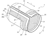
スリーブ部材20は、筒状に形成されている。スリーブ部材20は、貫通孔6Hの内面形状に対応する形状の筒状(円筒状、楕円筒状、及び多角筒状等)に形成されている。本実施形態のように区画体6の貫通孔6Hが円形状である場合には、スリーブ部材20は円筒状に形成される。本実施形態では、スリーブ部材20の軸方向Lの長さL1は、区画体6の軸方向Lの厚みにほぼ等しく(図2を参照)、スリーブ部材20の周方向Cの長さC1は、貫通孔6Hの内周面の周長にほぼ等しい。図3に示すように、本実施形態では、スリーブ部材20は、一体的に形成されているとともに、周方向Cの1箇所で軸方向Lの全域に亘って分断されている。そして、スリーブ部材20は、周方向Cの両側の分断端部20Eどうしが周方向Cに対向する状態(突き当てられた状態又は若干の隙間を隔てて向かい合う状態)で円筒状をなすように構成されている。通常の使用状態において筒状をなすスリーブ部材20は、建築物の区画体6に形成された貫通孔6Hの内面に沿って、当該貫通孔6Hに挿入(内挿)される。スリーブ部材20は、例えば樹脂材料、金属材料、及びセラミック材料等で形成されており、全体として一定以上の剛性及び強度を有している。   The sleeve member 20 is formed in a cylindrical shape. The sleeve member 20 is formed in a cylindrical shape (cylindrical shape, elliptical cylindrical shape, polygonal cylindrical shape, etc.) corresponding to the shape of the inner surface of the through hole 6H. When the through hole 6H of the partition 6 is circular as in the present embodiment, the sleeve member 20 is formed in a cylindrical shape. In this embodiment, the length L1 of the sleeve member 20 in the axial direction L is substantially equal to the thickness of the partition member 6 in the axial direction L (see FIG. 2), and the length C1 of the sleeve member 20 in the circumferential direction C is It is substantially equal to the peripheral length of the inner peripheral surface of the through hole 6H. As shown in FIG. 3, in the present embodiment, the sleeve member 20 is integrally formed and is divided across the entire region in the axial direction L at one place in the circumferential direction C. The sleeve member 20 has a cylindrical shape in a state where the split end portions 20E on both sides in the circumferential direction C face each other in the circumferential direction C (abutted state or a state facing each other with a slight gap). It is configured. The sleeve member 20 having a cylindrical shape in a normal use state is inserted (interpolated) into the through hole 6H along the inner surface of the through hole 6H formed in the partition body 6 of the building. The sleeve member 20 is made of, for example, a resin material, a metal material, a ceramic material, or the like, and has a certain level of rigidity and strength as a whole.

なお、本実施形態では、スリーブ部材20は、外力が作用しない状態で分断端部20Eどうしが周方向Cに離間して、貫通孔6Hよりも僅かに大径の円筒状をなすように構成されている。この場合、スリーブ部材20を貫通孔6Hに挿入する際には、分断端部20Eどうしを近づけ(典型的には突き当て)、スリーブ部材20を縮径させてから貫通孔6Hに挿入する。このようにすれば、貫通孔6Hの内周面と当該貫通孔6H内で再度拡径するスリーブ部材20の外周面とを密着させることができ、両者間に隙間が生じるのを有効に抑制することができる。   In the present embodiment, the sleeve member 20 is configured such that the divided end portions 20E are separated from each other in the circumferential direction C in a state in which no external force is applied, and has a cylindrical shape slightly larger in diameter than the through hole 6H. Has been. In this case, when the sleeve member 20 is inserted into the through hole 6H, the divided end portions 20E are brought close to each other (typically abutting), and the sleeve member 20 is reduced in diameter before being inserted into the through hole 6H. In this way, the inner peripheral surface of the through hole 6H and the outer peripheral surface of the sleeve member 20 that expands again in the through hole 6H can be brought into close contact with each other, and the occurrence of a gap between them can be effectively suppressed. be able to.

スリーブ部材20は、スリーブ本体部21と、このスリーブ本体部21の軸方向Lの一方の端部(後述する開放側端部28)に設けられたフランジ部22とを含む。本実施形態では、スリーブ本体部21は、周方向Cの両端部どうしが周方向Cに対向するように円筒状に湾曲した湾曲板状部として形成されている。フランジ部22は、スリーブ本体部21から径方向外側に向かって延びる状態で、スリーブ本体部21と一体的に形成されている。フランジ部22は、全周に亘って設けられている。スリーブ本体部21におけるフランジ部22が設けられた側とは反対側の端部(後述する一体化端部26)の外面には、テーパー面23が形成されている。このテーパー面23は、スリーブ本体部21における一体化端部26の外面に、当該一体化端部26の端縁26e側に向かうに従って次第に縮径するように形成されている。   The sleeve member 20 includes a sleeve main body portion 21 and a flange portion 22 provided at one end portion (an open side end portion 28 described later) of the sleeve main body portion 21 in the axial direction L. In the present embodiment, the sleeve main body 21 is formed as a curved plate-like portion that is curved in a cylindrical shape so that both end portions in the circumferential direction C are opposed to each other in the circumferential direction C. The flange portion 22 is formed integrally with the sleeve main body portion 21 so as to extend radially outward from the sleeve main body portion 21. The flange portion 22 is provided over the entire circumference. A tapered surface 23 is formed on the outer surface of the end portion (integrated end portion 26 to be described later) opposite to the side on which the flange portion 22 is provided in the sleeve main body portion 21. The tapered surface 23 is formed on the outer surface of the integrated end portion 26 in the sleeve main body 21 so as to gradually reduce the diameter toward the end edge 26 e side of the integrated end portion 26.

なお、このスリーブ部材20は、防火措置構造が適用される区画体6が中実壁である場合にも設けられる。また、スリーブ部材20は、区画体6が中空壁である場合には、当該中空壁からなる区画体6の貫通孔6Hに既に長尺体7が挿通された状態で設置される。この点で、本実施形態の防火措置ユニット1に備えられるスリーブ部材20は、中空壁からなる区画体6の貫通孔6Hに長尺体7に先立って予め設置される一般的な“貫通スリーブ”とは、使用目的及び施工態様が異なる。この点については、後述する。   In addition, this sleeve member 20 is provided also when the division body 6 to which a fire-protection structure is applied is a solid wall. Moreover, when the division body 6 is a hollow wall, the sleeve member 20 is installed in a state where the long body 7 has already been inserted into the through hole 6H of the division body 6 made of the hollow wall. In this regard, the sleeve member 20 provided in the fire protection unit 1 of the present embodiment is a general “penetrating sleeve” that is installed in advance in the through hole 6H of the partition body 6 formed of a hollow wall prior to the long body 7. Is different from the purpose of use and construction mode. This point will be described later.

耐火パック部材30は、貫通孔6Hと長尺体7との間の隙間空間Sを閉塞するための部材である。耐火パック部材30は柔軟性を有する。本実施形態の耐火パック部材30は、柔軟性を有する袋体31と、この袋体31の内部に封入されたペースト状の熱膨張性耐火材32とを含む。本実施形態では、熱膨張性耐火材32が「充填材」に相当し、耐火パック部材30が「パック部材」及び「閉塞部材」に相当する。袋体31は、例えば可燃性のプラスチックフィルム(例えばポリエチレンフィルムやナイロンフィルム等)で形成することができる。熱膨張性耐火材32は、熱膨張性(加熱により体積が増加する性質)と耐火性(火熱に耐えやすい性質、溶融温度が高く燃えにくい性質)とを有する部材である。熱膨張性耐火材32としては、公知の材質のものを特に制限なく用いることができ、例えばパテ状部材(熱膨張性パテ状耐火材)を用いることができる。但し、本実施形態の熱膨張性耐火材32は、可塑剤(水性の場合は水、油性の場合は油)の含有量が通常よりも多く、全体としてペースト状となっている。   The fireproof pack member 30 is a member for closing the gap space S between the through hole 6 </ b> H and the elongated body 7. The fireproof pack member 30 has flexibility. The fireproof pack member 30 of the present embodiment includes a flexible bag body 31 and a paste-like thermally expandable fireproof material 32 enclosed in the bag body 31. In the present embodiment, the thermally expandable refractory material 32 corresponds to a “filler”, and the refractory pack member 30 corresponds to a “pack member” and a “closure member”. The bag body 31 can be formed, for example with a combustible plastic film (for example, a polyethylene film, a nylon film, etc.). The heat-expandable refractory material 32 is a member having thermal expansibility (property that increases in volume by heating) and fire resistance (property that can easily withstand heat and properties that have high melting temperature and are difficult to burn). As the heat-expandable refractory material 32, a known material can be used without particular limitation. For example, a putty-like member (heat-expandable putty-like refractory material) can be used. However, the heat-expandable refractory material 32 of this embodiment has a plasticizer content (water in the case of water, oil in the case of oil) more than usual, and is in the form of a paste as a whole.

このペースト状の熱膨張性耐火材32は、公知のパテ状耐火材に比べて十分に柔らかい。従来のパテ状耐火材は稠度が50〜80程度であるのに対して、本実施形態のペースト状の熱膨張性耐火材32は、その稠度が例えば80〜400程度である。このような柔らかい熱膨張性耐火材32を柔軟性のある袋体31に封入して用いることで、耐火パック部材30は比較的自由に変形させることが可能となっている。そして、耐火パック部材30を変形させることで、互いに隣り合う長尺体7のそれぞれの外面に亘る谷間空間Vを熱膨張性耐火材32で容易に埋めることが可能となっている。ペースト状の熱膨張性耐火材32の稠度は、耐火パック部材30の変形を容易化する観点からは、大きい方が好ましい。熱膨張性耐火材32の稠度は、例えば150〜390程度が好ましく、300〜380程度がさらに好ましい。もちろん、耐火パック部材30単体でのダレ防止の観点から、例えば稠度が300以下の熱膨張性耐火材32を用いても良い。   This paste-like thermally expandable refractory material 32 is sufficiently soft as compared with a known putty-like refractory material. While the conventional putty-like refractory material has a consistency of about 50 to 80, the paste-like thermally expandable refractory material 32 of this embodiment has a consistency of about 80 to 400, for example. By using such a soft thermally expandable refractory material 32 enclosed in a flexible bag 31, the fireproof pack member 30 can be deformed relatively freely. Then, by deforming the fireproof pack member 30, it is possible to easily fill the valley space V across the outer surfaces of the adjacent long bodies 7 with the thermally expandable fireproof material 32. From the viewpoint of facilitating the deformation of the fireproof pack member 30, the consistency of the paste-like thermally expandable fireproof material 32 is preferably larger. For example, the consistency of the heat-expandable refractory material 32 is preferably about 150 to 390, and more preferably about 300 to 380. Of course, from the viewpoint of preventing sagging of the fireproof pack member 30 alone, for example, a thermally expandable fireproof material 32 having a consistency of 300 or less may be used.

なお、本明細書において、「稠度」は、JIS K2235 5.4.2(1)に規定される針入度計を用いて、JIS K2220 5.3(ちょう度試験方法)に規定されるちょう度計における針及びおもりを円錐に置き換えて測定するものとする。より具体的には、試料中に上記の円錐を垂直に5秒間進入させ、円錐が進入した深さを0.1mm単位で測定し、これを10倍した値(無名数)を「稠度」とする。ここで、円錐はJIS K2235 5.10.2(2)図9に示される形状・寸法のもので、その質量は102.5±0.05gとし、円錐を支える保持具はJIS K2235 5.4.2(3)に規定されるもので、その質量は47.5±0.05gとする。   In the present specification, “consistency” is defined in JIS K2220 5.3 (Consistency test method) using a penetration meter defined in JIS K2235 5.4.2 (1). The needle and weight in the dynamometer shall be replaced with a cone for measurement. More specifically, the above-mentioned cone is allowed to enter the sample vertically for 5 seconds, the depth at which the cone has entered is measured in units of 0.1 mm, and a value obtained by multiplying this by 10 (nameless number) is referred to as “consistency”. To do. Here, the cone has the shape and dimensions shown in JIS K2235 5.10.2 (2), and its mass is 102.5 ± 0.05 g, and the holder that supports the cone is JIS K2235 5.4. .2 (3) and its mass shall be 47.5 ± 0.05 g.

熱膨張性耐火材32は、例えば200℃以上に加熱された際に、その厚み方向に膨張する。熱膨張性耐火材32を含む耐火パック部材30の熱膨張率は、例えば2倍〜40倍等であって良い。   The thermally expandable refractory material 32 expands in the thickness direction when heated to, for example, 200 ° C. or higher. The thermal expansion coefficient of the fireproof pack member 30 including the heat-expandable fireproof material 32 may be, for example, 2 to 40 times.

耐火パック部材30は、スリーブ部材20に対して周方向Cに沿って重ねて配置されている。耐火パック部材30は、スリーブ部材20の周方向Cの全域において、当該スリーブ部材20の径方向内側に重ねて配置されている。また、スリーブ部材20と耐火パック部材30とが重ねて配置された状態で、軸方向Lの一端にて、スリーブ本体部21と袋体31とが一体化されている。スリーブ本体部21と袋体31とを一体化するための一体化手段としては、接着剤(接着層)、熱融着、クリップ部材、フック部材、及びハトメ部材等を、特に制限なく利用することができる。本実施形態では、この一体化手段は、スリーブ部材20の周方向Cの全域に亘って連続的に設けられている。言い換えれば、スリーブ本体部21と袋体31とは、スリーブ部材20の周方向Cの全域に亘って連続的に一体化されている。   The fireproof pack member 30 is disposed so as to overlap the sleeve member 20 along the circumferential direction C. The fireproof pack member 30 is disposed so as to overlap the inner side in the radial direction of the sleeve member 20 in the entire circumferential direction C of the sleeve member 20. In addition, the sleeve main body 21 and the bag body 31 are integrated at one end in the axial direction L in a state where the sleeve member 20 and the fireproof pack member 30 are arranged to overlap each other. As an integration means for integrating the sleeve main body 21 and the bag body 31, an adhesive (adhesive layer), heat fusion, a clip member, a hook member, a grommet member, and the like are used without particular limitation. Can do. In the present embodiment, this integration means is provided continuously over the entire area in the circumferential direction C of the sleeve member 20. In other words, the sleeve main body 21 and the bag body 31 are continuously integrated over the entire area in the circumferential direction C of the sleeve member 20.

本実施形態では、耐火パック部材30の周方向Cの長さC2が、スリーブ部材20の周方向Cの長さC1よりも長く設定されている。耐火パック部材30は、スリーブ部材20と周方向Cの一端を揃えて配置されている。これにより、本実施形態の耐火パック部材30は、スリーブ部材20と周方向Cの端部を揃えた側の端部とは反対側の端部に、図4に示す展開状態でスリーブ部材20から周方向Cに延出して径方向視でスリーブ部材20とは重ならない周方向延出部33を有する。このような周方向延出部33を有することにより、耐火パック部材30は、図3に示す筒状への組立状態で、その周方向Cの両端部が互いに重複可能となっている。つまり、筒状への組立状態で、スリーブ部材20は分断端部20Eどうしが対向して重複部分のない円筒状になるのに対して、耐火パック部材30は、周方向延出部33の存在によって周方向Cの両端部が互いに重複する円筒状となる。   In the present embodiment, the length C2 of the fireproof pack member 30 in the circumferential direction C is set to be longer than the length C1 of the sleeve member 20 in the circumferential direction C. The fireproof pack member 30 is arranged with the sleeve member 20 and one end in the circumferential direction C aligned. Thereby, the fireproof pack member 30 of the present embodiment is separated from the sleeve member 20 in the unfolded state shown in FIG. 4 at the end opposite to the end on the side where the end in the circumferential direction C is aligned with the sleeve member 20. A circumferentially extending portion 33 that extends in the circumferential direction C and does not overlap the sleeve member 20 when viewed in the radial direction is provided. By having such a circumferentially extending portion 33, the fireproof pack member 30 can be overlapped at both ends in the circumferential direction C in the assembled state shown in FIG. That is, in the assembled state in the cylindrical shape, the sleeve member 20 becomes a cylindrical shape with the overlapping end portions 20 </ b> E facing each other and without an overlapping portion, whereas the fireproof pack member 30 is formed of the circumferentially extending portion 33. Due to the presence, both end portions in the circumferential direction C have a cylindrical shape overlapping each other.

また、本実施形態では、耐火パック部材30の軸方向Lの長さL2が、スリーブ部材20の軸方向Lの長さL1よりも長く設定されている。耐火パック部材30は、スリーブ部材20と軸方向Lの一端(一体化端部26,36)を揃えて配置されている。これにより、耐火パック部材30におけるスリーブ部材20と一体化されていない方の開放側端部38が、スリーブ部材20における耐火パック部材30と一体化されていない方の開放側端部28から突出している。すなわち、本実施形態の耐火パック部材30は、一体化端部36とは反対側の端部であってスリーブ部材20とは一体化されていない方の端部(開放側端部38)に、スリーブ部材20から軸方向Lに延出して径方向視でスリーブ部材20とは重ならない軸方向延出部34を有する。このような軸方向延出部34を有することにより、内部に封入される熱膨張性耐火材32の量を一定量確保しながら、耐火パック部材30の薄型化を図ることが可能となっている。   In the present embodiment, the length L2 of the fireproof pack member 30 in the axial direction L is set to be longer than the length L1 of the sleeve member 20 in the axial direction L. The fireproof pack member 30 is arranged so that the sleeve member 20 and one end in the axial direction L (integrated end portions 26 and 36) are aligned. Thereby, the open side end portion 38 of the fireproof pack member 30 that is not integrated with the sleeve member 20 protrudes from the open side end portion 28 of the sleeve member 20 that is not integrated with the fireproof pack member 30. Yes. That is, the fireproof pack member 30 of the present embodiment is an end opposite to the integrated end 36 and is not integrated with the sleeve member 20 (open side end 38). It has an axially extending portion 34 that extends in the axial direction L from the sleeve member 20 and does not overlap the sleeve member 20 when viewed in the radial direction. By having such an axially extending portion 34, it is possible to reduce the thickness of the fireproof pack member 30 while securing a certain amount of the thermally expandable fireproof material 32 sealed inside. .

以下、本実施形態の防火措置ユニット1を用いて実現される防火措置構造の施工手順について説明する。まず、図5に示すように、建築物の区画体6に形成された貫通孔6Hに複数の長尺体7の束が配置された状態で、貫通孔6Hの外側で、一束の長尺体7の周囲を取り囲むように防火措置ユニット1を配置する。このとき、スリーブ部材20の分断端部20Eどうしを互いに離間させて拡開させた状態で、一束の長尺体7の周囲に防火措置ユニット1を配置する。その際、軸方向Lにおけるスリーブ部材20と耐火パック部材30とが一体化されている方の端部(一体化端部26,36)が区画体6側に位置する状態となるように防火措置ユニット1を配置する。   Hereinafter, the construction procedure of the fire protection structure realized using the fire protection unit 1 of the present embodiment will be described. First, as shown in FIG. 5, in a state where a bundle of a plurality of long bodies 7 is arranged in a through hole 6 </ b> H formed in a partition body 6 of a building, a long bundle of long outside the through hole 6 </ b> H. The fire protection unit 1 is arranged so as to surround the body 7. At this time, the fire protection unit 1 is arranged around the bundle of long bodies 7 in a state where the divided end portions 20E of the sleeve member 20 are separated from each other and expanded. At that time, the fire prevention measures are taken so that the end portions (integrated end portions 26, 36) in which the sleeve member 20 and the fireproof pack member 30 in the axial direction L are integrated are positioned on the partition body 6 side. Unit 1 is arranged.

その後、分断端部20Eどうしを近づけて周方向Cに対向させ、スリーブ部材20を筒状とする。その際、耐火パック部材30の周方向延出部33が径方向内側に配置された状態となるように、耐火パック部材30の周方向Cの両端部を重ねて配置する。この状態で、互いに隣り合う長尺体7のそれぞれの外面に亘る複数の谷間空間Vのうち、最も大きい谷間空間Vの位置に周方向延出部33が配置されるように、耐火パック部材30の周方向Cの位置を調整することが好ましい。このようにすれば、相対的に多量の熱膨張性耐火材32が必要となる最大の谷間空間Vを、二重に重ねて配置される分の周方向延出部33の熱膨張性耐火材32で、十分に埋めることができる。なお、そのような構成に限定されることなく、当初より、最も大きい谷間空間Vの位置に周方向延出部33を配置しつつ一束の長尺体7の周囲に防火措置ユニット1を配置することによって、耐火パック部材30の位相調整を行っても良い。   Thereafter, the divided end portions 20E are brought close to each other so as to face each other in the circumferential direction C, and the sleeve member 20 is formed into a cylindrical shape. At that time, both end portions in the circumferential direction C of the fireproof pack member 30 are overlapped so that the circumferentially extending portion 33 of the fireproof pack member 30 is disposed inward in the radial direction. In this state, the fireproof pack member 30 is arranged such that the circumferentially extending portion 33 is disposed at the position of the largest valley space V among the plurality of valley spaces V extending over the outer surfaces of the long bodies 7 adjacent to each other. It is preferable to adjust the position in the circumferential direction C. In this way, the thermal expansion refractory material of the circumferentially extending portion 33 corresponding to the maximum valley space V, which requires a relatively large amount of the thermal expansion refractory material 32, is arranged in a double layer. 32 can be sufficiently filled. In addition, without being limited to such a configuration, the fire protection unit 1 is disposed around the bundle of long bodies 7 while disposing the circumferentially extending portion 33 at the position of the largest valley space V from the beginning. By doing so, the phase of the fireproof pack member 30 may be adjusted.

次に、防火措置ユニット1を、軸方向Lにおけるスリーブ部材20と耐火パック部材30とが一体化されている方の一体化端部26,36側から貫通孔6Hに挿入する。このとき、耐火パック部材30が高稠度のペースト状の熱膨張性耐火材32を内包して形成されて柔らかい場合であっても、貫通孔6Hと複数の長尺体7との間の隙間空間Sに、一定以上の剛性を有するスリーブ部材20と共に耐火パック部材30を容易に奥まで挿入することができる。よって、区画体6の貫通孔6Hに対して防火措置を施す際の施工性を向上させることができる。スリーブ本体部21における一体化端部26の外面にはテーパー面23が形成されているので、このテーパー面23による案内作用により、防火措置ユニット1の一端を容易に貫通孔6Hの内部へと導くことができる。スリーブ本体部21の開放側端部28には外向きのフランジ部22が設けられてその厚みが増されているので、防火措置ユニット1を軸方向Lに押し込む押込操作も容易である。   Next, the fire protection unit 1 is inserted into the through-hole 6H from the side of the integrated ends 26 and 36 where the sleeve member 20 and the fireproof pack member 30 in the axial direction L are integrated. At this time, even if the fireproof pack member 30 is formed by including a paste-like heat-expandable fireproof material 32 having a high consistency and is soft, a gap space between the through-hole 6H and the plurality of long bodies 7 is used. The fireproof pack member 30 can be easily inserted into S together with the sleeve member 20 having a certain level of rigidity. Therefore, the workability at the time of applying a fire prevention measure to the through-hole 6H of the partition 6 can be improved. Since the tapered surface 23 is formed on the outer surface of the integrated end portion 26 in the sleeve main body 21, one end of the fire protection unit 1 is easily guided to the inside of the through hole 6 </ b> H by the guiding action by the tapered surface 23. be able to. Since the outward flange portion 22 is provided on the open side end portion 28 of the sleeve main body portion 21 and the thickness thereof is increased, the pushing operation for pushing the fire protection unit 1 in the axial direction L is also easy.

防火措置ユニット1の押込操作は、フランジ部22が区画体6の表面に当接するまで実施される(図2及び図6を参照)。この状態で、スリーブ部材20及び耐火パック部材30の一体化端部26,36が、区画体6の反対側の表面の位置に到達する。当該位置では、耐火パック部材30がスリーブ部材20に対して周方向Cの全域に亘って一体化されているので、耐火パック部材30が高稠度のペースト状の熱膨張性耐火材32を内包して形成されて柔らかい場合であっても、ダレの発生を効果的に抑制できる。特に、稠度が300以上の熱膨張性耐火材32を内包する耐火パック部材30を用いる場合であっても、ダレの発生を有効に抑制することができる。よって、耐火パック部材30の保形性を長期間に亘って維持することができる。   The push-in operation of the fire protection unit 1 is performed until the flange portion 22 comes into contact with the surface of the partition body 6 (see FIGS. 2 and 6). In this state, the integrated ends 26 and 36 of the sleeve member 20 and the fireproof pack member 30 reach the position of the surface on the opposite side of the partition body 6. At this position, the fireproof pack member 30 is integrated with the sleeve member 20 over the entire area in the circumferential direction C, so that the fireproof pack member 30 contains the paste-like thermally expandable fireproof material 32 having a high consistency. Even if it is formed and soft, the occurrence of sagging can be effectively suppressed. In particular, even when the fireproof pack member 30 containing the heat-expandable fireproof material 32 having a consistency of 300 or more is used, the occurrence of sagging can be effectively suppressed. Therefore, the shape retention of the fireproof pack member 30 can be maintained over a long period of time.

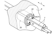
その後、図6に示すように、軸方向Lにおいてスリーブ部材20の開放側端部28から突出している耐火パック部材30の軸方向延出部34を、貫通孔6Hの内部へと押し込む。そして、耐火パック部材30における開放側端部38を含む領域であり、当該耐火パック部材30におけるスリーブ部材20と一体化されていない非一体化部分37の一部でもある軸方向延出部34を、互いに隣り合う長尺体7のそれぞれの外面に亘る谷間空間Vに配置する。その際、図7に示すように、耐火パック部材30の軸方向延出部34を含む非一体化部分37を、谷間空間Vに対応する形状に変形した状態で、当該谷間空間Vに配置する。耐火パック部材30は、高稠度のペースト状の熱膨張性耐火材32を内包して形成されて非常に柔らかいので、一束の長尺体7の外面に形成される複数の谷間空間Vに容易に形状追従させることができる。よって、複数の谷間空間Vも含めて貫通孔6Hと長尺体7との間の隙間空間Sを十分に埋めることができる。このとき、フランジ部22が区画体6の表面に当接しているので、耐火パック部材30の押込作業時に、その押込操作につられて防火措置ユニット1が軸方向Lに移動することがない。   Then, as shown in FIG. 6, the axially extending portion 34 of the fireproof pack member 30 protruding from the open end 28 of the sleeve member 20 in the axial direction L is pushed into the through hole 6H. And the axial direction extension part 34 which is an area | region including the open side edge part 38 in the fireproof pack member 30, and is also a part of the non-integrated part 37 which is not integrated with the sleeve member 20 in the fireproof pack member 30. In the valley space V over the outer surface of each of the long bodies 7 adjacent to each other. At that time, as shown in FIG. 7, the non-integrated portion 37 including the axially extending portion 34 of the fireproof pack member 30 is arranged in the valley space V in a state of being deformed into a shape corresponding to the valley space V. . The refractory pack member 30 is formed of a highly viscous paste-like heat-expandable refractory material 32 and is very soft. Therefore, the refractory pack member 30 is easily formed in a plurality of valley spaces V formed on the outer surface of the bundle of long bodies 7. Can follow the shape. Therefore, the gap space S between the through hole 6H and the elongated body 7 including the plurality of valley spaces V can be sufficiently filled. At this time, since the flange portion 22 is in contact with the surface of the partition body 6, the fire protection unit 1 is not moved in the axial direction L by the pushing operation when the fireproof pack member 30 is pushed.

建築物において火災が発生すると、火炎の熱によって周囲温度が上昇し、長尺体7を構成する被覆材71Bが溶融・燃焼し、貫通孔6Hと長尺体7との間の隙間空間Sがさらに拡大する可能性がある。この場合であっても、周囲温度の上昇に応じて耐火パック部材30に内包された熱膨張性耐火材32が熱膨張して、被覆材71Bの溶融・燃焼によって生じる空間を埋める(言い換えれば、隙間容積の増加分を補填する)ことができる。特に本実施形態では、柔らかい耐火パック部材30を谷間空間Vに形状追従させることで谷間空間Vが十分に埋められているので、十分な防火性能が付与される。従って、本実施形態の防火措置ユニット1を用いることで、施工性に優れ、且つ、十分な防火性能をもたらす防火措置構造を実現することができる。   When a fire occurs in a building, the ambient temperature rises due to the heat of the flame, the covering material 71B constituting the long body 7 melts and burns, and a gap space S between the through hole 6H and the long body 7 is formed. There is a possibility of further expansion. Even in this case, the thermally expandable refractory material 32 contained in the refractory pack member 30 is thermally expanded in accordance with an increase in the ambient temperature, and fills the space generated by melting and burning the covering material 71B (in other words, To compensate for the increase in the gap volume). In particular, in this embodiment, since the valley space V is sufficiently filled by causing the soft fireproof pack member 30 to follow the shape of the valley space V, sufficient fire prevention performance is imparted. Therefore, by using the fire protection unit 1 of the present embodiment, it is possible to realize a fire protection structure that is excellent in workability and provides sufficient fire prevention performance.

〔第2の実施形態〕
本発明に係る貫通孔措置ユニット及び貫通孔措置構造の第2の実施形態について、図面を参照して説明する。本実施形態も、本発明に係る貫通孔措置ユニット及び貫通孔措置構造を防火措置ユニット1及びそれを用いた防火措置構造に適用した例である。本実施形態では、防火措置ユニット1の具体的構成が第1の実施形態とは一部異なっている。以下、本実施形態の防火措置ユニット1及び防火措置構造について、主に第1の実施形態との相違点について説明する。なお、特に明記しない点に関しては、第1の実施形態と同様であり、同一の符号を付して詳細な説明は省略する。
[Second Embodiment]
2nd Embodiment of the through-hole measure unit and through-hole measure structure which concern on this invention is described with reference to drawings. This embodiment is also an example in which the through-hole measure unit and the through-hole measure structure according to the present invention are applied to the fire-proof measure unit 1 and the fire-proof measure structure using the same. In the present embodiment, the specific configuration of the fire protection unit 1 is partially different from that of the first embodiment. Hereinafter, the difference between the fire protection unit 1 and the fire protection structure of the present embodiment and the first embodiment will be mainly described. Note that the points not particularly specified are the same as those in the first embodiment, and the same reference numerals are given and detailed description thereof is omitted.

図8に示すように、本実施形態の防火措置ユニット1は、筒状のスリーブ部材20と、熱膨張性耐火材32を内包する耐火パック部材30とに加え、ガイド部材40をさらに備えている。ガイド部材40は、例えば樹脂材料、金属材料、及びセラミック材料等で形成され、全体として一定以上の剛性及び強度を有していることが好ましい。   As shown in FIG. 8, the fire protection unit 1 of the present embodiment further includes a guide member 40 in addition to the cylindrical sleeve member 20 and the fireproof pack member 30 containing the thermally expandable fireproof material 32. . The guide member 40 is preferably made of, for example, a resin material, a metal material, a ceramic material, or the like, and preferably has a certain level of rigidity and strength as a whole.

ガイド部材40は、耐火パック部材30の開放側端部38にて、耐火パック部材30の袋体31と一体化されている。ガイド部材40は、耐火パック部材30の径方向外側に配置された状態で、耐火パック部材30と一体化されている。本実施形態では、ガイド部材40と耐火パック部材30とは、周方向Cの全域に亘って連続的に一体化されている。ガイド部材40は、耐火パック部材30の軸方向延出部34と径方向視で重なる状態で、耐火パック部材30と一体化されている。スリーブ部材20とガイド部材40とは、耐火パック部材30に対して同じ側となる径方向外側で、軸方向Lにおける互いに反対側の端部にて耐火パック部材30と一体化されている。   The guide member 40 is integrated with the bag body 31 of the fireproof pack member 30 at the open end 38 of the fireproof pack member 30. The guide member 40 is integrated with the fireproof pack member 30 in a state where the guide member 40 is disposed on the radially outer side of the fireproof pack member 30. In the present embodiment, the guide member 40 and the fireproof pack member 30 are continuously integrated over the entire region in the circumferential direction C. The guide member 40 is integrated with the fireproof pack member 30 so as to overlap the axially extending portion 34 of the fireproof pack member 30 in the radial direction. The sleeve member 20 and the guide member 40 are integrated with the fireproof pack member 30 at the opposite ends in the axial direction L on the radially outer side which is the same side with respect to the fireproof pack member 30.

本実施形態では、ガイド部材40は、スリーブ部材20のスリーブ本体部21の形状に対応する形状のガイド本体部41と、耐火パック部材30と一体化された側の端部に設けられたフランジ部42とを含む。本実施形態では、ガイド本体部41は、円筒状のスリーブ本体部21の内径と同程度の外径を有する円筒状に形成されている。フランジ部42は、ガイド本体部41から径方向内側に向かって延びる状態で、ガイド本体部41と一体的に形成されている。   In this embodiment, the guide member 40 includes a guide main body portion 41 having a shape corresponding to the shape of the sleeve main body portion 21 of the sleeve member 20 and a flange portion provided at an end portion on the side integrated with the fireproof pack member 30. 42. In the present embodiment, the guide main body 41 is formed in a cylindrical shape having an outer diameter comparable to the inner diameter of the cylindrical sleeve main body 21. The flange portion 42 is formed integrally with the guide main body portion 41 so as to extend radially inward from the guide main body portion 41.

ガイド部材40の周方向Cの長さは、スリーブ部材20の周方向Cの長さC1と同程度に設定されても良いし(図8を参照)、或いは、それよりも長く設定されても良い。前者の場合には、ガイド部材40の周方向Cの端部どうしが周方向Cに対向する状態(突き当てられた状態又は若干の隙間を隔てて向かい合う状態)で、ガイド部材40が筒状をなす。後者の場合には、ガイド部材40の周方向Cの端部どうしが重ねられた状態で、ガイド部材40が筒状をなす。   The length in the circumferential direction C of the guide member 40 may be set to be approximately the same as the length C1 in the circumferential direction C of the sleeve member 20 (see FIG. 8) or may be set longer than that. good. In the former case, the guide member 40 has a cylindrical shape in a state where the end portions in the circumferential direction C of the guide member 40 face each other in the circumferential direction C (abutted state or a state facing each other with a slight gap). Eggplant. In the latter case, the guide member 40 has a cylindrical shape with the end portions in the circumferential direction C of the guide member 40 being overlapped with each other.

ガイド部材40の軸方向Lの長さは、耐火パック部材30の軸方向延出部34の軸方向Lの長さと同程度に又はそれよりも短く設定されても良いし(図8を参照)、或いは、軸方向延出部34の軸方向Lの長さよりも長く設定されても良い。前者の場合には、ガイド本体部41におけるフランジ部42が設けられた側とは反対側の端部の外面には、端縁側に向かうに従って次第に縮径するテーパー面が形成されても良い。   The length in the axial direction L of the guide member 40 may be set to be the same as or shorter than the length in the axial direction L of the axially extending portion 34 of the fireproof pack member 30 (see FIG. 8). Alternatively, it may be set longer than the length of the axially extending portion 34 in the axial direction L. In the former case, a tapered surface that gradually decreases in diameter toward the end edge may be formed on the outer surface of the end of the guide main body 41 opposite to the side on which the flange portion 42 is provided.

本実施形態の防火措置ユニット1を用いて防火措置構造を実現するには、第1の実施形態と同様にして区画体6の貫通孔6Hに防火措置ユニット1の全体を押込操作した後、貫通孔6Hにスリーブ部材20が保持された状態で、図9に示すようにガイド部材40を対象とする第2の押込操作を実施する。この第2の押込操作により、筒状のガイド部材40は、スリーブ部材20に対して、当該スリーブ部材20の開放側端部28側から内挿される。ガイド部材40は、ガイド本体部41におけるフランジ部42が設けられた側とは反対側の端部を先頭として、スリーブ部材20に対して軸方向Lに沿って内挿される。このとき、ガイド本体部41における挿入方向後端には内向きのフランジ部42が設けられてその厚みが増されているので、第2の押込操作を容易に行うことができる。   In order to realize the fire protection structure using the fire protection unit 1 of the present embodiment, the entire fire protection unit 1 is pushed into the through-hole 6H of the partition body 6 in the same manner as in the first embodiment, and then penetrated. In a state where the sleeve member 20 is held in the hole 6H, a second pushing operation for the guide member 40 is performed as shown in FIG. By this second pushing operation, the cylindrical guide member 40 is inserted into the sleeve member 20 from the open end 28 side of the sleeve member 20. The guide member 40 is inserted along the axial direction L with respect to the sleeve member 20 with the end of the guide main body 41 opposite to the side on which the flange portion 42 is provided as the head. At this time, since the inward flange portion 42 is provided at the rear end of the guide main body portion 41 in the insertion direction and the thickness thereof is increased, the second pushing operation can be easily performed.

ガイド部材40は耐火パック部材30の開放側端部38と一体化されているので、第1の押込操作後の状態ではスリーブ部材20の開放側端部28から突出して未挿入となっていた耐火パック部材30の軸方向延出部34が、第2の押込操作に伴い、ガイド部材40と共にスリーブ部材20の内側空間に挿入される。よって、ガイド部材40を押込操作するだけで、耐火パック部材30の開放側端部38を直接的に操作することなくスリーブ部材20の内側空間に挿入することができる。その後、耐火パック部材30における非一体化部分37を、互いに隣り合う長尺体7のそれぞれの外面に亘る谷間空間Vに押し込んで配置する。耐火パック部材30は、高稠度のペースト状の熱膨張性耐火材32を内包して形成されて非常に柔らかいので、一束の長尺体7の外面に形成される複数の谷間空間Vに容易に形状追従させることができる。よって、複数の谷間空間Vも含めて貫通孔6Hと長尺体7との間の隙間空間Sを十分に埋めることができる。   Since the guide member 40 is integrated with the open side end portion 38 of the fireproof pack member 30, the fireproof portion that protrudes from the open side end portion 28 of the sleeve member 20 and is not inserted after the first pushing operation has been performed. The axially extending portion 34 of the pack member 30 is inserted into the inner space of the sleeve member 20 together with the guide member 40 in accordance with the second pushing operation. Therefore, it is possible to insert the open side end portion 38 of the fireproof pack member 30 into the inner space of the sleeve member 20 by directly operating the guide member 40 without operating it. Thereafter, the non-integrated portion 37 of the fireproof pack member 30 is disposed by being pushed into the valley space V over the outer surfaces of the adjacent elongated bodies 7. The refractory pack member 30 is formed of a highly viscous paste-like heat-expandable refractory material 32 and is very soft. Therefore, the refractory pack member 30 is easily formed in a plurality of valley spaces V formed on the outer surface of the bundle of long bodies 7. Can follow the shape. Therefore, the gap space S between the through hole 6H and the elongated body 7 including the plurality of valley spaces V can be sufficiently filled.

本実施形態では、スリーブ部材20及び耐火パック部材30の一体化端部26,36とは反対側の端部の位置において、耐火パック部材30が、スリーブ部材20の径方向内側に保持されたガイド部材40に対して周方向Cの全域に亘って一体化されている。このように、耐火パック部材30は、軸方向Lの両端部のそれぞれにおいて、他の筒状部材に対して周方向Cの全域で一体化されているので、ダレの発生をさらに効果的に抑制することができる。よって、耐火パック部材30が高稠度のペースト状の熱膨張性耐火材32を内包して形成されて柔らかい場合であっても、耐火パック部材30の保形性を長期間に亘って維持することができる。   In the present embodiment, the guide in which the fireproof pack member 30 is held on the radially inner side of the sleeve member 20 at the position of the end opposite to the integrated ends 26 and 36 of the sleeve member 20 and the fireproof pack member 30. The member 40 is integrated over the entire region in the circumferential direction C. Thus, since the fireproof pack member 30 is integrated in the whole area in the circumferential direction C with respect to the other cylindrical members at each of both end portions in the axial direction L, the occurrence of sagging is more effectively suppressed. can do. Therefore, even if the fireproof pack member 30 is formed by including the paste-like thermally expandable fireproof material 32 having a high consistency and is soft, the shape retention of the fireproof pack member 30 is maintained for a long period of time. Can do.

〔第3の実施形態〕
本発明に係る貫通孔措置ユニット及び貫通孔措置構造の第3の実施形態について、図面を参照して説明する。本実施形態も、本発明に係る貫通孔措置ユニット及び貫通孔措置構造を防火措置ユニット1及びそれを用いた防火措置構造に適用した例である。本実施形態では、スリーブ部材20と一体化されて当該スリーブ部材20と共に貫通孔6Hに挿入される部材が第1及び第2の実施形態とは異なっている。以下、本実施形態の防火措置ユニット1及び防火措置構造について、主に第1の実施形態との相違点について説明する。なお、特に明記しない点に関しては、第1の実施形態と同様であり、同一の符号を付して詳細な説明は省略する。
[Third Embodiment]
3rd Embodiment of the through-hole measure unit and through-hole measure structure which concern on this invention is described with reference to drawings. This embodiment is also an example in which the through-hole measure unit and the through-hole measure structure according to the present invention are applied to the fire-proof measure unit 1 and the fire-proof measure structure using the same. In the present embodiment, a member that is integrated with the sleeve member 20 and inserted into the through hole 6H together with the sleeve member 20 is different from the first and second embodiments. Hereinafter, the difference between the fire protection unit 1 and the fire protection structure of the present embodiment and the first embodiment will be mainly described. Note that the points not particularly specified are the same as those in the first embodiment, and the same reference numerals are given and detailed description thereof is omitted.

図11に示すように、本実施形態の防火措置ユニット1は、筒状のスリーブ部材20と、熱膨張性耐火材51Bを主体とする耐火シート部材50とを備えている。耐火シート部材50は、貫通孔6Hと長尺体7との間の隙間空間Sを閉塞するための部材であり、シート状(薄板状)に形成されている。本実施形態では、耐火シート部材50が「シート状部材」及び「閉塞部材」に相当する。本実施形態の耐火シート部材50は、熱膨張性耐火シート51で構成されている。   As shown in FIG. 11, the fire protection unit 1 of the present embodiment includes a cylindrical sleeve member 20 and a fireproof sheet member 50 mainly composed of a thermally expandable fireproof material 51B. The refractory sheet member 50 is a member for closing the gap space S between the through hole 6H and the long body 7, and is formed in a sheet shape (thin plate shape). In the present embodiment, the refractory sheet member 50 corresponds to a “sheet-like member” and a “closing member”. The fireproof sheet member 50 of the present embodiment is composed of a thermally expandable fireproof sheet 51.

熱膨張性耐火シート51は、基体シート51Aと、熱膨張性耐火材51Bと、被覆シート51Cとが互いに積層されて構成されている。基体シート51Aは、例えばアルミワリフ、アルミガラスクロス、及びアルミクラフト等の金属製薄膜シートで構成することができる。熱膨張性耐火材51Bは、熱膨張性と耐火性とを有する部材であり、例えば熱膨張性基材と無機充填材と樹脂成分とを含有する樹脂組成物で構成することができる。熱膨張性基材としては、例えば熱膨張性黒鉛、アルカリ金属ケイ酸塩、及び未焼成バーミキュライト粉末等が例示される。無機充填材としては、例えば各種の無機フィラー等が例示される。樹脂成分としては、例えばエチレン・プロピレン・ジエンゴムやエチレン酢酸ビニルコポリマー、ブチルゴム等が例示される。熱膨張性耐火材51Bは、例えば200℃以上に加熱された際に、その厚み方向に膨張する。被覆シート51Cは、例えばポリエチレンフィルムやナイロンフィルム等の樹脂フィルムで構成することができる。なお、基体シート51Aを樹脂フィルムで構成し、被覆シート51Cを金属製薄膜シートで構成する等しても良い。   The heat-expandable fireproof sheet 51 is configured by laminating a base sheet 51A, a heat-expandable fireproof material 51B, and a covering sheet 51C. The base sheet 51A can be composed of a metal thin film sheet such as an aluminum walliff, an aluminum glass cloth, and an aluminum craft. The heat-expandable refractory material 51B is a member having heat-expandability and fire resistance, and can be composed of, for example, a resin composition containing a heat-expandable base material, an inorganic filler, and a resin component. Examples of the heat-expandable base material include heat-expandable graphite, alkali metal silicate, and unburned vermiculite powder. Examples of the inorganic filler include various inorganic fillers. Examples of the resin component include ethylene / propylene / diene rubber, ethylene vinyl acetate copolymer, and butyl rubber. The thermally expandable refractory material 51B expands in the thickness direction when heated to, for example, 200 ° C. or higher. The covering sheet 51C can be formed of a resin film such as a polyethylene film or a nylon film, for example. The base sheet 51A may be made of a resin film, and the covering sheet 51C may be made of a metal thin film sheet.

熱膨張性耐火シート51は、主に熱膨張性耐火材51Bの厚みに応じて、全体として所定厚さ(例えば1.5mm〜10mm)を有するように形成されている。また、熱膨張性耐火シート51は、主に熱膨張性耐火材51Bの構成材料に応じて、可撓性(たわめることが可能な性質)を有するように形成されている。熱膨張性耐火シート51で構成される耐火シート部材50は、柔軟性を有してはいるものの、第1の実施形態や第2の実施形態で説明した耐火パック部材30に比べると、柔軟性の程度は遥かに低い。耐火シート部材50は、柔軟性(可撓性)を有しつつ、ある程度の定形性をも有するように形成されている。   The heat-expandable fireproof sheet 51 is formed so as to have a predetermined thickness (for example, 1.5 mm to 10 mm) as a whole, mainly depending on the thickness of the heat-expandable fireproof material 51B. The thermally expandable refractory sheet 51 is formed so as to have flexibility (a property that can be flexed) mainly depending on the constituent material of the thermally expandable refractory material 51B. Although the fireproof sheet member 50 composed of the heat-expandable fireproof sheet 51 has flexibility, it is more flexible than the fireproof pack member 30 described in the first embodiment or the second embodiment. Is much lower. The fireproof sheet member 50 is formed to have a certain degree of regularity while having flexibility (flexibility).

耐火シート部材50は、スリーブ部材20に対して周方向Cに沿って重ねて配置されている。また、スリーブ部材20と耐火シート部材50とが重ねて配置された状態で、軸方向Lの一端(一体化端部56)にて、スリーブ部材20と耐火シート部材50とが一体化されている。本実施形態のように所定厚さを有する耐火シート部材50を閉塞部材として用いる場合には、一体化手段は、例えば耐火シート部材50に形成された貫通孔に係止されるフック部材で構成することができる。この場合、複数のフック部材を、スリーブ部材20の軸方向Lの一端において周方向Cに分散して設けると良い。   The fireproof sheet member 50 is disposed so as to overlap the sleeve member 20 along the circumferential direction C. In addition, the sleeve member 20 and the fireproof sheet member 50 are integrated at one end (integrated end portion 56) in the axial direction L in a state where the sleeve member 20 and the fireproof sheet member 50 are arranged to overlap each other. . When the fireproof sheet member 50 having a predetermined thickness is used as the closing member as in the present embodiment, the integration unit is configured by a hook member that is locked to a through hole formed in the fireproof sheet member 50, for example. be able to. In this case, it is preferable to disperse the plurality of hook members in the circumferential direction C at one end in the axial direction L of the sleeve member 20.

耐火シート部材50の周方向Cの長さは、スリーブ部材20の周方向Cの長さよりも長く設定されている。そして、耐火シート部材50は、周方向Cの一端に、図12に示す展開状態でスリーブ部材20から周方向Cに延出して径方向視でスリーブ部材20とは重ならない周方向延出部53を有する。また、耐火シート部材50の軸方向Lの長さは、スリーブ部材20の軸方向Lの長さよりも長く設定されている。そして、耐火シート部材50は、一体化端部56とは反対側の端部であってスリーブ部材20とは一体化されていない方の端部(開放側端部58)に、スリーブ部材20から軸方向Lに延出して径方向視でスリーブ部材20とは重ならない軸方向延出部54を有する。   The length of the fireproof sheet member 50 in the circumferential direction C is set longer than the length of the sleeve member 20 in the circumferential direction C. And the fireproof sheet member 50 is extended in the circumferential direction C from the sleeve member 20 in the unfolded state shown in FIG. 12 at one end in the circumferential direction C, and the circumferentially extending portion 53 that does not overlap the sleeve member 20 in the radial direction. Have Further, the length of the fireproof sheet member 50 in the axial direction L is set longer than the length of the sleeve member 20 in the axial direction L. The refractory sheet member 50 is connected to the end portion (open side end portion 58) that is the end portion opposite to the integrated end portion 56 and not integrated with the sleeve member 20, from the sleeve member 20. It has an axially extending portion 54 that extends in the axial direction L and does not overlap the sleeve member 20 when viewed in the radial direction.

図12に示すように、本実施形態では、耐火シート部材50の開放側端部58に、軸方向Lに沿う複数のスリット52が周方向Cに分散して設けられている。ここで、「軸方向Lに沿う」とは、当該スリット52を全体として見た場合の延在方向が軸方向Lに平行となる状態(実質的に平行とみなせる程度に僅かに傾斜する状態を含む)を意味する。スリット52の軸方向Lの長さは、耐火シート部材50の軸方向Lの長さよりも短い。これら複数のスリット52により、耐火シート部材50は、周方向Cに並ぶ複数のスリット間部分51Pに区画されている。複数のスリット間部分51Pは、軸方向Lの一端側(一体化端部56側)において継ぎ目なく連続するように一体化されている。なお、周方向Cに隣り合う2つのスリット間部分51Pは、それらの間に設けられるスリット52に対して周方向Cの両側に隣接する部分でもあり、この意味でそれぞれ“スリット隣接部分”とも称することができる。   As shown in FIG. 12, in this embodiment, a plurality of slits 52 along the axial direction L are provided in the open direction end 58 of the fireproof sheet member 50 in a distributed manner in the circumferential direction C. Here, “along the axial direction L” means a state in which the extending direction when the slit 52 is viewed as a whole is parallel to the axial direction L (a state in which the slit 52 is slightly inclined so as to be considered substantially parallel). Means). The length of the slit 52 in the axial direction L is shorter than the length of the fireproof sheet member 50 in the axial direction L. By the plurality of slits 52, the fireproof sheet member 50 is partitioned into a plurality of inter-slit portions 51 </ b> P arranged in the circumferential direction C. The plurality of inter-slit portions 51P are integrated so as to be seamlessly continuous at one end side in the axial direction L (on the integrated end portion 56 side). The two slit-to-slit portions 51P adjacent in the circumferential direction C are also portions adjacent to both sides in the circumferential direction C with respect to the slits 52 provided therebetween, and in this sense, they are also referred to as “slit adjacent portions”, respectively. be able to.

スリット52の形成態様は任意であって良い。スリット52は、軸方向Lの位置によらない一定の周方向幅を有するように形成されても良いし、軸方向Lの位置に応じて周方向幅が異なるように形成されても良い。本実施形態では、スリット52は、一体化端部56側の底部52bから開放側端部58に向かうに従って周方向幅が次第に広くなるように、V字状(より具体的には、底部52bの周方向位置を通る仮想平面に対して線対称となるV字状)に形成されている。   The formation mode of the slit 52 may be arbitrary. The slit 52 may be formed to have a constant circumferential width that does not depend on the position in the axial direction L, or may be formed so that the circumferential width varies depending on the position in the axial direction L. In the present embodiment, the slit 52 is V-shaped (more specifically, the bottom 52b is formed so that the circumferential width gradually increases from the bottom 52b on the integrated end 56 side toward the open end 58. V-shape that is line-symmetric with respect to a virtual plane passing through the circumferential position.

スリット間部分51Pは、台形状に形成されている。スリット間部分51Pは、スリット52の形状(V字状)に応じて、一体化端部56側の基端部から開放側端部58に向かうに従って周方向幅が次第に狭くなる台形状(本例では等脚台形状)に形成されている。この場合、各スリット間部分51Pにおいて、開放側端部58の外面は台形状のスリット間部分51Pの“上底”相当箇所となり、スリット52に臨む各側面は“脚(きゃく)”相当箇所となる。   The inter-slit portion 51P is formed in a trapezoidal shape. The inter-slit portion 51P has a trapezoidal shape in which the circumferential width gradually decreases from the base end portion on the integrated end portion 56 side toward the open end portion 58 in accordance with the shape (V-shape) of the slit 52 (this example). Is formed in an isosceles trapezoidal shape. In this case, in each inter-slit portion 51P, the outer surface of the open-side end portion 58 is a portion corresponding to the “upper bottom” of the trapezoidal inter-slit portion 51P, and each side facing the slit 52 is a portion corresponding to the “leg”. Become.

このような構成の耐火シート部材50を用い、周方向Cに隣り合う2つの台形状のスリット間部分51Pの側面(“脚”相当箇所)どうしを互いに当接させることで、筒状となる耐火シート部材50を、開放側端部58に向かうに従って次第に縮径するようにテーパー状に形成できる。そして、筒状の耐火シート部材50の開放側端部58を、スリーブ部材20に比べて小径化することができ、好適には開放側端部58で長尺体7の外周を隙間なく覆うことができる。よって、貫通孔6Hと長尺体7との間の隙間空間Sが径方向に比較的広い場合でも、当該隙間空間Sを適切に埋めることができる。   Using the fireproof sheet member 50 having such a configuration, the side surfaces (corresponding to “legs”) of two trapezoidal slit-to-slit portions 51P adjacent to each other in the circumferential direction C are brought into contact with each other to form a cylindrical fireproof. The sheet member 50 can be formed in a tapered shape so that the diameter thereof is gradually reduced toward the open end 58. The opening-side end portion 58 of the tubular fire-resistant sheet member 50 can be made smaller in diameter than the sleeve member 20, and preferably, the outer periphery of the long body 7 is covered with the opening-side end portion 58 without a gap. Can do. Therefore, even when the gap space S between the through hole 6H and the elongated body 7 is relatively wide in the radial direction, the gap space S can be appropriately filled.

なお、耐火シート部材50のサイズ(特に開放側端部58側の開口の大きさ)と長尺体7のサイズとの関係次第では、周方向Cに隣り合うスリット間部分51Pどうしを部分的に重ねて配置したり、互いに離間して配置したりすると良い。例えば長尺体7が相対的に小さい場合には、スリット間部分51Pの周方向Cの端部どうしを重ねて配置することで、筒状の耐火シート部材50の開放側端部58をより小径化して、当該開放側端部58を長尺体7の外面に沿わせることができる。また、例えば長尺体7が相対的に大きい場合には、スリット間部分51Pの周方向Cの端部どうしを当接させることなく離間して配置することで、筒状の耐火シート部材50の開放側端部58を大径化して長尺体7の外面に沿わせることができる。その際、開放側端部58側の開口の大きさの微調整は、必ずしも全周に亘って均等に行う必要はなく、一束の長尺体7の配設状態に対応させて、周方向の位置に応じて異なるように行われても良い。   Depending on the relationship between the size of the refractory sheet member 50 (particularly, the size of the opening on the open side end portion 58 side) and the size of the elongated body 7, the inter-slit portions 51P adjacent in the circumferential direction C are partially separated. It is good to arrange in piles or to be separated from each other. For example, when the long body 7 is relatively small, the opening-side end portion 58 of the tubular refractory sheet member 50 has a smaller diameter by overlapping the end portions in the circumferential direction C of the inter-slit portion 51P. Thus, the open end 58 can be made to follow the outer surface of the long body 7. For example, when the long body 7 is relatively large, the end portions in the circumferential direction C of the inter-slit portion 51P are arranged apart from each other without being brought into contact with each other, so that the cylindrical fireproof sheet member 50 is disposed. It is possible to increase the diameter of the open-side end portion 58 so as to follow the outer surface of the long body 7. At that time, the fine adjustment of the size of the opening on the open end 58 side does not necessarily have to be performed uniformly over the entire circumference, and the circumferential direction corresponds to the arrangement state of the bundle of long bodies 7. It may be performed differently depending on the position.

〔その他の実施形態〕
(1)上記の各実施形態では、スリーブ部材20が一体的に形成されている構成を例として説明した。しかし、そのような構成に限定されることなく、例えばスリーブ部材20が全体として筒状をなす複数のスリーブ分割体で構成されても良い。また、スリーブ部材20は、例えば図13に示すように、その厚み方向に貫通する貫通部(肉抜き部分)24を有する筒状に形成されても良い。このようにすれば、閉塞部材として耐火パック部材30を用いる場合において、耐火パック部材30の非一体化部分37を押し込んで変形させる際に、当該非一体化部分37の少なくとも一部を、貫通部24を通って貫通孔6Hの内面に接するように配置することができる。よって、仮に貫通孔6Hの内面とスリーブ部材20の外面との間に微小隙間が存在する場合であっても、当該微小隙間も含めて、貫通孔6Hと長尺体7との間の隙間空間Sを十分に埋めることができる。さらに、熱膨張性耐火材32が加熱された際には、膨張した熱膨張性耐火材32が貫通部24を通って貫通孔6Hの内面を圧接する。よって、貫通孔6Hの内面とスリーブ部材20の外面との間に存在し得る微小隙間も含めて、貫通孔6Hと長尺体7との間の隙間空間Sを確実に遮蔽することができる。第3の実施形態のように耐火パック部材30に代えて耐火シート部材50を用いる場合でも、同様である。
[Other Embodiments]
(1) In the above embodiments, the configuration in which the sleeve member 20 is integrally formed has been described as an example. However, the present invention is not limited to such a configuration, and for example, the sleeve member 20 may be configured by a plurality of sleeve divided bodies that form a tubular shape as a whole. Further, as shown in FIG. 13, for example, the sleeve member 20 may be formed in a cylindrical shape having a penetrating portion (thickening portion) 24 penetrating in the thickness direction. In this case, when the fireproof pack member 30 is used as the closing member, when the non-integrated portion 37 of the fireproof pack member 30 is pushed in and deformed, at least a part of the non-integrated portion 37 is passed through the penetration portion. 24 can be arranged so as to be in contact with the inner surface of the through hole 6H. Therefore, even if there is a minute gap between the inner surface of the through hole 6H and the outer surface of the sleeve member 20, the gap space between the through hole 6H and the elongated body 7 including the minute gap is included. S can be filled sufficiently. Furthermore, when the heat-expandable refractory material 32 is heated, the expanded heat-expandable refractory material 32 passes through the through portion 24 and presses the inner surface of the through hole 6H. Therefore, the gap space S between the through hole 6H and the elongated body 7 can be reliably shielded including the minute gap that may exist between the inner surface of the through hole 6H and the outer surface of the sleeve member 20. The same applies to the case where the fireproof sheet member 50 is used instead of the fireproof pack member 30 as in the third embodiment.

(2)上記の各実施形態では、スリーブ部材20が当初から貫通孔6Hの内面形状に対応する形状の筒状をなしている構成を主に想定して説明した。しかし、そのような構成に限定されることなく、スリーブ部材20は少なくとも貫通孔6Hへの挿入時に筒状となれば良く、挿入前の段階では例えば平板状をなす等、他の形状を呈するものであっても良い。 (2) In each of the above embodiments, the description has been given mainly assuming the configuration in which the sleeve member 20 has a cylindrical shape corresponding to the shape of the inner surface of the through hole 6H from the beginning. However, the sleeve member 20 is not limited to such a configuration, and the sleeve member 20 only needs to be cylindrical at least when inserted into the through-hole 6H. The sleeve member 20 has another shape such as a flat plate shape before insertion. It may be.

(3)上記の各実施形態では、スリーブ部材20が、スリーブ本体部21における開放側端部28に全周に亘るフランジ部22を有する構成を例として説明した。しかし、そのような構成に限定されることなく、例えばフランジ部22が周方向に沿って断続的に設けられても良い。或いは、スリーブ部材20にフランジ部22が設けられなくても良い。 (3) In each of the above embodiments, the configuration in which the sleeve member 20 has the flange portion 22 over the entire circumference at the open side end portion 28 of the sleeve main body portion 21 has been described as an example. However, without being limited to such a configuration, for example, the flange portion 22 may be provided intermittently along the circumferential direction. Alternatively, the flange portion 22 may not be provided on the sleeve member 20.

(4)上記の各実施形態では、スリーブ部材20が、スリーブ本体部21における一体化端部26側の外面にテーパー面23を有する構成を例として説明した。しかし、そのような構成に限定されることなく、例えばスリーブ部材20がテーパー面23を備えなくても良い。 (4) In each of the above embodiments, the configuration in which the sleeve member 20 has the tapered surface 23 on the outer surface of the sleeve main body portion 21 on the integrated end portion 26 side has been described as an example. However, the configuration is not limited to such a configuration. For example, the sleeve member 20 may not include the tapered surface 23.

(5)上記の第1及び第2の実施形態では、耐火パック部材30が周方向Cの一方側のみに周方向延出部33を有する構成を例として説明した。しかし、そのような構成に限定されることなく、耐火パック部材30が周方向Cの両側に周方向延出部33を有しても良い。但し、2つの周方向延出部33のうちの一方は、スリーブ部材20が分断端部20Eどうしを周方向Cに対向させて筒状となるのを妨げない程度の大きさとされる。第3の実施形態のように耐火パック部材30に代えて耐火シート部材50を用いる場合でも、同様である。 (5) In the above-described first and second embodiments, the configuration in which the fireproof pack member 30 has the circumferential extending portion 33 only on one side in the circumferential direction C has been described as an example. However, the fireproof pack member 30 may include the circumferentially extending portions 33 on both sides in the circumferential direction C without being limited to such a configuration. However, one of the two circumferentially extending portions 33 has a size that does not prevent the sleeve member 20 from becoming a cylindrical shape with the divided end portions 20E facing each other in the circumferential direction C. The same applies to the case where the fireproof sheet member 50 is used instead of the fireproof pack member 30 as in the third embodiment.

(6)上記の第1及び第2の実施形態では、耐火パック部材30が展開状態でスリーブ部材20とは重ならない周方向延出部33及び軸方向延出部34の両方を有する構成を例として説明した。しかし、そのような構成に限定されることなく、例えば耐火パック部材30が、周方向延出部33及び軸方向延出部34の少なくとも一方を有さなくても良い。第3の実施形態のように耐火パック部材30に代えて耐火シート部材50を用いる場合でも、同様である。 (6) In said 1st and 2nd embodiment, the structure which has both the circumferential direction extension part 33 and the axial direction extension part 34 which the fireproof pack member 30 does not overlap with the sleeve member 20 in the expansion | deployment state is an example As explained. However, without being limited to such a configuration, for example, the fireproof pack member 30 may not have at least one of the circumferentially extending portion 33 and the axially extending portion 34. The same applies to the case where the fireproof sheet member 50 is used instead of the fireproof pack member 30 as in the third embodiment.

(7)上記の第1及び第2の実施形態では、袋体31の内部にペースト状の熱膨張性耐火材32のみが封入されている耐火パック部材30を用いる構成を主に想定して説明した。しかし、そのような構成に限定されることなく、耐火パック部材30として、袋体31の内部に、ペースト状の熱膨張性耐火材32に加えて、非ペースト状の充填材として例えば無機繊維や無機球体等の他の成分を封入したものを用いても良い。 (7) In said 1st and 2nd embodiment, the structure using the fireproof pack member 30 by which only the paste-form thermally expansible fireproof material 32 is enclosed in the bag body 31 is mainly assumed, and is demonstrated. did. However, without being limited to such a configuration, as the fireproof pack member 30, in addition to the paste-like thermally expandable refractory material 32 inside the bag body 31, non-paste-like fillers such as inorganic fibers or You may use what enclosed other components, such as an inorganic sphere.

(8)上記の第1及び第2の実施形態では、スリーブ部材20と耐火パック部材30とが、袋体31の周縁部のみ(「軸方向Lの一端」の一例)で一体化されている構成を主に想定して説明した。しかし、そのような構成に限定されることなく、耐火パック部材30に十分な大きさの非一体化部分37が確保される限り、スリーブ部材20と耐火パック部材30とが所定範囲(例えば、軸方向Lの一端から中央部までの領域)に亘って一体化されても良い。或いは、スリーブ部材20と耐火パック部材30とが、軸方向Lの一端を含む複数箇所で一体化されても良い。 (8) In the first and second embodiments described above, the sleeve member 20 and the fireproof pack member 30 are integrated only in the peripheral portion of the bag body 31 (an example of “one end in the axial direction L”). The description has been given mainly assuming the configuration. However, without being limited to such a configuration, as long as a sufficiently large non-integrated portion 37 is secured in the fireproof pack member 30, the sleeve member 20 and the fireproof pack member 30 are within a predetermined range (for example, a shaft). It may be integrated over a region from one end in the direction L to the center portion). Alternatively, the sleeve member 20 and the fireproof pack member 30 may be integrated at a plurality of locations including one end in the axial direction L.

(9)上記の第1及び第2の実施形態では、単一のスリーブ部材20と単一の耐火パック部材30とが一体化されている構成を例として説明した。しかし、そのような構成に限定されることなく、例えば1つのスリーブ部材20に対して複数の耐火パック部材30が設けられ、1つのスリーブ部材20と複数の耐火パック部材30とが一体化されても良い。この場合において、周方向Cに互いに隣り合う一対の耐火パック部材30は、周方向Cの端部どうしを重ねた状態で配置されても良い。第3の実施形態のように耐火パック部材30に代えて耐火シート部材50を用いる場合でも、同様である。 (9) In the first and second embodiments, the configuration in which the single sleeve member 20 and the single fireproof pack member 30 are integrated has been described as an example. However, without being limited to such a configuration, for example, a plurality of fireproof pack members 30 are provided for one sleeve member 20, and the one sleeve member 20 and the plurality of fireproof pack members 30 are integrated. Also good. In this case, the pair of fireproof pack members 30 adjacent to each other in the circumferential direction C may be arranged in a state where the ends in the circumferential direction C are overlapped. The same applies to the case where the fireproof sheet member 50 is used instead of the fireproof pack member 30 as in the third embodiment.

(10)上記第2の実施形態では、ガイド部材40が一体的に形成されている構成を例として説明した。しかし、そのような構成に限定されることなく、例えばガイド部材40が全体として筒状をなす複数のガイド分割体で構成されても良い。また、ガイド部材40は、例えばその厚み方向に貫通する貫通部(肉抜き部分)を有する筒状に形成されても良い。或いは、ガイド部材40は、例えば針金等の芯材を用いて、当該芯材を全体として筒状又は環状に組んで形成されても良い。 (10) In the second embodiment, the configuration in which the guide member 40 is integrally formed has been described as an example. However, without being limited to such a configuration, for example, the guide member 40 may be configured by a plurality of guide divided bodies having a cylindrical shape as a whole. Moreover, the guide member 40 may be formed in the cylinder shape which has the penetration part (thickening part) penetrated in the thickness direction, for example. Alternatively, the guide member 40 may be formed by using a core material such as a wire, for example, and assembling the core material into a tubular shape or an annular shape as a whole.

(11)上記第2の実施形態では、耐火パック部材30とガイド部材40とが周方向Cの全域に亘って一体化されている構成を例として説明した。しかし、そのような構成に限定されることなく、例えば耐火パック部材30とガイド部材40とが周方向Cに断続的に一体化されても良い。 (11) In the second embodiment, the configuration in which the fireproof pack member 30 and the guide member 40 are integrated over the entire region in the circumferential direction C has been described as an example. However, without being limited to such a configuration, for example, the fireproof pack member 30 and the guide member 40 may be intermittently integrated in the circumferential direction C.

(12)上記第3の実施形態では、ある程度の定形性を具備させるべく、耐火シート部材50が所定厚さを有するように形成されている構成を例として説明した。しかし、そのような構成に限定されることなく、耐火シート部材50が、例えば厚みが1mm以下の薄膜シート状に形成されても良い。 (12) In the third embodiment, the configuration in which the refractory sheet member 50 is formed to have a predetermined thickness has been described as an example so as to have a certain degree of regularity. However, without being limited to such a configuration, the fireproof sheet member 50 may be formed into a thin film sheet having a thickness of 1 mm or less, for example.

(13)上記第3の実施形態では、耐火シート部材50の開放側端部58に、軸方向Lに沿う複数のスリット52が周方向Cに分散して設けられている構成を例として説明した。しかし、そのような構成に限定されることなく、耐火シート部材50にスリット52が1つだけ設けられても良い。 (13) In the third embodiment, the configuration in which the plurality of slits 52 along the axial direction L are provided in the circumferential direction C at the open end 58 of the fireproof sheet member 50 has been described as an example. . However, it is not limited to such a configuration, and only one slit 52 may be provided in the fireproof sheet member 50.

(14)上記第3の実施形態では、耐火シート部材50にV字状のスリット52が形成されている構成を例として説明した。しかし、そのような構成に限定されることなく、スリット52は例えば直線状に形成されても良い。また、スリット52は必ずしも当初より形成されていなくても良く、耐火シート部材50が、スリット52を容易に形成可能とするための構造(「スリット前駆部」と言う。)を備え、施工時に必要に応じて事後的にスリット52を現出可能に構成されても良い。スリット前駆部は、例えばミシン線やハーフカット線等で構成することができる。そのようなスリット前駆部を有する耐火シート部材50は、実際にはスリット52が未出の状態であっても、「スリット52が設けられている」とみなすことができる。なお、耐火シート部材50には、スリット52(スリット前駆部を含む)は必ずしも形成されなくても良い。 (14) In the third embodiment, the configuration in which the V-shaped slit 52 is formed in the fireproof sheet member 50 has been described as an example. However, the slit 52 may be formed in a straight line, for example, without being limited to such a configuration. Moreover, the slit 52 does not necessarily need to be formed from the beginning, and the fireproof sheet member 50 includes a structure (referred to as a “slit precursor”) that allows the slit 52 to be easily formed, and is necessary at the time of construction. Depending on the situation, the slit 52 may be made visible afterwards. A slit precursor part can be comprised, for example with a sewing machine line, a half cut line, etc. The refractory sheet member 50 having such a slit precursor can be regarded as “provided with the slit 52” even if the slit 52 is not actually present. In addition, the slit 52 (including the slit precursor) is not necessarily formed in the fireproof sheet member 50.

(15)上記の各実施形態では、建築物の区画体6に形成された貫通孔6Hと複数の長尺体7の束との間の隙間空間Sに対する防火措置構造(防火措置ユニット1)を例として説明した。しかし、そのような構成に限定されることなく、例えば貫通孔6Hと1本の長尺体7との間の隙間空間Sに対する防火措置構造(防火措置ユニット1)に対しても、同様に本発明を適用することができる。 (15) In each of the above embodiments, the fire prevention structure (fire prevention unit 1) for the gap space S between the through hole 6H formed in the partition 6 of the building and the bundle of the plurality of long bodies 7 is provided. Described as an example. However, the present invention is not limited to such a configuration. For example, the present invention is similarly applied to the fire prevention structure (fire prevention unit 1) for the gap space S between the through-hole 6H and one long body 7. The invention can be applied.

(16)上記の各実施形態では、袋体31の内部に熱膨張性耐火材32が封入されている耐火パック部材30又は熱膨張性耐火材51Bを主体とする耐火シート部材50を含む防火措置ユニット1を用いた防火措置構造を例として説明した。しかし、そのような構成に限定されることなく、例えば耐火性又は非耐火性の区画体6に形成された貫通孔6Hを単に埋めるための貫通孔措置構造(貫通孔措置ユニット)に対しても、本発明を適用することができる。この場合、閉塞部材として、例えば、袋体31と、その袋体31の内部に封入された繊維材やパテ材等の非耐火性の充填材とを含むパック部材を用いても良い。これらの場合において、内部に封入される充填材の性状次第では(例えば漏出等の心配がない場合には)、袋体31を繊維シート(例えば織物や不織布等)で構成する等、袋体31の材質は任意であって良い。或いは、一定形状を有しつつ柔軟性をも有する繊維材(例えばロックウール、セラミックウール、及びグラスウール等の無機繊維材)等からなる充填材を、袋体31に封入することなくそのまま閉塞部材として用いても良い。この場合、繊維材等からなる充填材を例えばシート状又は直方体状等に成形したものを用いても良い。このような閉塞部材をスリーブ部材20と一体化させて備える貫通孔措置ユニットであっても、同様に、施工性に優れ、且つ、貫通孔6Hと長尺体7との間の隙間空間Sを十分に埋めることができる貫通孔措置構造を実現できる。 (16) In each of the above-described embodiments, the fire protection measures include the fireproof pack member 30 in which the thermally expandable fireproof material 32 is sealed inside the bag body 31 or the fireproof sheet member 50 mainly composed of the thermally expandable fireproof material 51B. The fire prevention structure using the unit 1 has been described as an example. However, the present invention is not limited to such a configuration. For example, a through-hole measure structure (through-hole measure unit) for simply filling the through-hole 6H formed in the fireproof or non-fireproof compartment 6 is also used. The present invention can be applied. In this case, as the closing member, for example, a pack member including a bag body 31 and a non-fire-resistant filler such as a fiber material or a putty material sealed in the bag body 31 may be used. In these cases, depending on the properties of the filler filled inside (for example, when there is no concern about leakage or the like), the bag body 31 may be formed of a fiber sheet (for example, a woven fabric or a nonwoven fabric). The material of may be arbitrary. Alternatively, a filler made of a fibrous material having a certain shape and also having flexibility (for example, inorganic fiber materials such as rock wool, ceramic wool, and glass wool) or the like can be used as a closing member without being enclosed in the bag 31. It may be used. In this case, a filler formed of a fiber material or the like, for example, formed into a sheet shape or a rectangular parallelepiped shape may be used. Even in the case of a through-hole measure unit provided with such a closing member integrated with the sleeve member 20, the workability is excellent and the clearance space S between the through-hole 6H and the elongated body 7 is similarly provided. A through-hole measure structure that can be sufficiently filled can be realized.

なお、上述した各実施形態(上記の各実施形態及びその他の実施形態を含む;以下同様)で開示される構成は、矛盾が生じない限り、他の実施形態で開示される構成と組み合わせて適用することも可能である。   The configuration disclosed in each of the above-described embodiments (including each of the above-described embodiments and other embodiments; the same applies hereinafter) is applied in combination with the configuration disclosed in the other embodiments unless a contradiction arises. It is also possible to do.

その他の構成に関しても、本明細書において開示された実施形態は全ての点で例示であって、本発明の範囲はそれらによって限定されることはないと理解されるべきである。当業者であれば、本発明の趣旨を逸脱しない範囲内で、適宜改変が可能であることを容易に理解できるであろう。従って、本発明の趣旨を逸脱しない範囲で改変された別の実施形態も、当然、本発明の範囲に含まれる。   Regarding other configurations, it should be understood that the embodiments disclosed herein are illustrative in all respects and that the scope of the present invention is not limited thereby. Those skilled in the art will readily understand that modifications can be made as appropriate without departing from the spirit of the present invention. Accordingly, other embodiments modified without departing from the spirit of the present invention are naturally included in the scope of the present invention.

1 防火措置ユニット(貫通孔措置ユニット)
6 区画体
6H 貫通孔
7 長尺体
20 スリーブ部材
22 フランジ部
23 テーパー面
26 一体化端部
26e 端縁
28 開放側端部
30 耐火パック部材(閉塞部材、パック部材)
31 袋体
32 熱膨張性耐火材(充填材)
33 周方向延出部
34 軸方向延出部
36 一体化端部
37 非一体化部分
38 開放側端部
40 ガイド部材
50 耐火シート部材(閉塞部材、シート状部材)
52 スリット
58 開放側端部
S 隙間空間
V 谷間空間
L 軸方向
C 周方向
1 Fire protection unit (through-hole measure unit)
6 division body 6H through-hole 7 elongate body 20 sleeve member 22 flange portion 23 taper surface 26 integrated end portion 26e end edge 28 open side end portion 30 fireproof pack member (blocking member, pack member)
31 Bag 32 Thermally expandable refractory material (filler)
33 circumferentially extending portion 34 axially extending portion 36 integrated end 37 non-integrated portion 38 open side end 40 guide member 50 refractory sheet member (blocking member, sheet-like member)
52 Slit 58 Open side end S Gap space V Valley space L Axial direction C Circumferential direction

Claims (10)

建築物の区画体に形成された貫通孔に、挿入側端部から軸方向に挿入される筒状のスリーブ部材と、
柔軟性を有する閉塞部材と、を備え、
前記閉塞部材が前記スリーブ部材に対して周方向に沿って重ねて配置されているとともに、前記スリーブ部材の前記挿入側端部にて前記スリーブ部材と前記閉塞部材とが一体化され、かつ、前記スリーブ部材の軸方向における前記挿入側端部とは反対側の端部にて前記スリーブ部材と前記閉塞部材とが非一体となっている貫通孔措置ユニット。
A cylindrical sleeve member inserted in the axial direction from the insertion side end into the through hole formed in the partition of the building,
A closure member having flexibility,
The closing member is disposed so as to overlap the sleeve member along the circumferential direction, and the sleeve member and the closing member are integrated at the insertion side end of the sleeve member , and A through-hole measure unit in which the sleeve member and the closing member are not integrated with each other at the end opposite to the insertion-side end in the axial direction of the sleeve member .
前記閉塞部材の周方向の長さが前記スリーブ部材の周方向の長さよりも長く、前記閉塞部材の周方向の両端部が互いに重複可能となっている請求項1に記載の貫通孔措置ユニット。   2. The through-hole measure unit according to claim 1, wherein a circumferential length of the closing member is longer than a circumferential length of the sleeve member, and both end portions in the circumferential direction of the closing member can overlap each other. 前記スリーブ部材が、軸方向における前記挿入側端部の外面に、当該挿入側端部の端縁側に向かうに従って次第に縮径するテーパー面を有する請求項1又は2に記載の貫通孔措置ユニット。 The through-hole measure unit according to claim 1 or 2, wherein the sleeve member has a tapered surface that gradually decreases in diameter toward an end edge side of the insertion side end portion on an outer surface of the insertion side end portion in the axial direction. 前記閉塞部材の軸方向の長さが前記スリーブ部材の軸方向の長さよりも長く、前記閉塞部材における前記スリーブ部材と非一体となっている方の開放側端部が、前記スリーブ部材における前記閉塞部材と非一体となっている方の開放側端部から突出している請求項1から3のいずれか一項に記載の貫通孔措置ユニット。 The length of the closing member in the axial direction is longer than the length of the sleeve member in the axial direction, and the opening-side end portion of the closing member that is not integrated with the sleeve member is the closing portion of the sleeve member. The through-hole measure unit according to any one of claims 1 to 3, wherein the through-hole measure unit protrudes from an open end portion that is not integrated with the member. 前記スリーブ部材に対して当該スリーブ部材の前記開放側端部側から内挿されるガイド部材をさらに備え、
前記閉塞部材の前記開放側端部にて前記ガイド部材と前記閉塞部材とが一体化されている請求項4に記載の貫通孔措置ユニット。
A guide member inserted into the sleeve member from the open side end side of the sleeve member;
The through-hole measure unit according to claim 4, wherein the guide member and the closing member are integrated at the open side end of the closing member.
前記閉塞部材が、柔軟性を有する袋体と当該袋体の内部に封入されたペースト状の充填材とを含むパック部材である請求項1から5のいずれか一項に記載の貫通孔措置ユニット。   The through-hole measure unit according to any one of claims 1 to 5, wherein the closing member is a pack member including a flexible bag body and a paste-like filler enclosed in the bag body. . 前記閉塞部材が、可撓性を有するシート状部材である請求項1から5のいずれか一項に記載の貫通孔措置ユニット。   The through hole measure unit according to any one of claims 1 to 5, wherein the closing member is a flexible sheet-like member. 前記シート状部材における前記スリーブ部材と非一体となっている方の開放側端部に、軸方向に沿うスリットが設けられている請求項7に記載の貫通孔措置ユニット。 The through-hole measure unit according to claim 7, wherein a slit along the axial direction is provided at an open side end portion of the sheet-like member that is not integrated with the sleeve member. 前記スリットが、前記開放側端部に向かうに従って周方向幅が次第に広くなるV字状に形成されている請求項8に記載の貫通孔措置ユニット。   The through-hole measure unit according to claim 8, wherein the slit is formed in a V shape whose width in the circumferential direction gradually increases toward the open end. 建築物の区画体に形成された貫通孔と前記貫通孔に挿通される複数の長尺体の束との間に設けられる貫通孔措置構造であって、
前記貫通孔に挿入される筒状のスリーブ部材と、柔軟性を有する閉塞部材と、を備え、前記閉塞部材が前記スリーブ部材に対して周方向に沿って重ねて配置されているとともに、前記スリーブ部材の軸方向の一端にて前記スリーブ部材と前記閉塞部材とが一体化されている貫通孔措置ユニットを用い、
前記貫通孔措置ユニットが、軸方向における前記スリーブ部材と前記閉塞部材とが一体化されている方の一体化端部側から前記貫通孔に挿入されており、
前記閉塞部材における前記スリーブ部材と一体化されていない非一体化部分が、互いに隣り合う前記長尺体のそれぞれの外面に亘る谷間空間に、当該谷間空間に対応する形状に変形した状態で配置されている貫通孔措置構造。
A through-hole measure structure provided between a through-hole formed in a partition of a building and a bundle of a plurality of long bodies inserted through the through-hole,
A cylindrical sleeve member to be inserted into the through-hole, and a flexible closing member, wherein the closing member is disposed so as to overlap the sleeve member in the circumferential direction, and the sleeve Using a through-hole measure unit in which the sleeve member and the closing member are integrated at one end in the axial direction of the member,
The through-hole measure unit is inserted into the through-hole from the integrated end side where the sleeve member and the closing member in the axial direction are integrated,
A non-integrated portion of the closing member that is not integrated with the sleeve member is disposed in a valley space extending over each outer surface of the elongated bodies adjacent to each other in a deformed state corresponding to the valley space. Through-hole measures structure.
JP2016192785A 2015-10-02 2016-09-30 Through-hole measure unit and through-hole measure structure Active JP6150933B2 (en)

Applications Claiming Priority (2)

Application Number Priority Date Filing Date Title
JP2015196963 2015-10-02

Related Child Applications (1)

Application Number Title Priority Date Filing Date
JP2017095667A Division JP6748028B2 (en) 2015-10-02 2017-05-12 Through-hole measure unit

Publications (2)

Publication Number Publication Date
JP2017070199A JP2017070199A (en) 2017-04-06
JP6150933B2 true JP6150933B2 (en) 2017-06-21

Family

ID=58495514

Family Applications (3)

Application Number Title Priority Date Filing Date
JP2016192785A Active JP6150933B2 (en) 2015-10-02 2016-09-30 Through-hole measure unit and through-hole measure structure
JP2017095667A Active JP6748028B2 (en) 2015-10-02 2017-05-12 Through-hole measure unit
JP2020133679A Active JP7038767B2 (en) 2015-10-02 2020-08-06 Through hole measures unit

Family Applications After (2)

Application Number Title Priority Date Filing Date
JP2017095667A Active JP6748028B2 (en) 2015-10-02 2017-05-12 Through-hole measure unit
JP2020133679A Active JP7038767B2 (en) 2015-10-02 2020-08-06 Through hole measures unit

Country Status (1)

Country Link
JP (3) JP6150933B2 (en)

Cited By (1)

* Cited by examiner, † Cited by third party
Publication number Priority date Publication date Assignee Title
JP2021019948A (en) * 2019-07-29 2021-02-18 積水化学工業株式会社 Section penetration treatment structure, section penetration treatment material, and section penetration treatment structure construction method

Families Citing this family (17)

* Cited by examiner, † Cited by third party
Publication number Priority date Publication date Assignee Title
JP6902756B2 (en) * 2017-12-06 2021-07-14 井上商事株式会社 Fire protection compartment penetration kit and fire protection compartment penetration structure
JP6895933B2 (en) * 2018-08-31 2021-06-30 古河電気工業株式会社 Fire protection member, fire protection structure and its construction method
JP6952017B2 (en) * 2018-08-31 2021-10-20 古河電気工業株式会社 Fire protection member, manufacturing method of fire protection member and fire protection structure
CN109723912B (en) * 2019-01-22 2024-04-19 中国科学院理化技术研究所 Signal line transmission structure
EP3974033A4 (en) * 2019-05-23 2023-06-21 Furukawa Electric Co., Ltd. Fire resistant member, fire preventing structure, and method for installing fire preventing structure
EP3809029A1 (en) * 2019-10-15 2021-04-21 Hilti Aktiengesellschaft Cable duct
JP7030148B2 (en) * 2020-03-03 2022-03-04 因幡電機産業株式会社 Fireproof compartment structure, how to build fireproof compartment structure
JP7034369B2 (en) * 2020-03-03 2022-03-11 因幡電機産業株式会社 Fireproof compartment structure, how to build fireproof compartment structure
JP7270086B2 (en) * 2020-03-03 2023-05-09 因幡電機産業株式会社 Fire-resistant compartment structure, construction method of fire-resistant compartment structure
JP6980878B1 (en) * 2020-09-23 2021-12-15 因幡電機産業株式会社 Gap closing unit
JP6980879B1 (en) * 2020-09-23 2021-12-15 因幡電機産業株式会社 Gap closing method and gap closing unit
JP7527917B2 (en) 2020-09-29 2024-08-05 因幡電機産業株式会社 Bagged fireproofing materials
JP7505970B2 (en) 2020-11-24 2024-06-25 未来工業株式会社 Wall penetration piping device and partition wall penetration structure
JP7508435B2 (en) 2021-10-22 2024-07-01 古河電気工業株式会社 Fireproof construction
SE545508C2 (en) * 2022-05-03 2023-10-03 Hellbergs Doerrar I Mellerud Ab A fire isolating door comprising a door hole insert
JP7556005B2 (en) 2022-10-03 2024-09-25 因幡電機産業株式会社 Gap Closure Unit
JP2024067432A (en) * 2022-11-04 2024-05-17 株式会社プロテリアル Electric penetration assembly

Family Cites Families (10)

* Cited by examiner, † Cited by third party
Publication number Priority date Publication date Assignee Title
US5103609A (en) * 1990-11-15 1992-04-14 Minnesota Mining & Manufacturing Company Intumescable fire stop device
JPH07180238A (en) * 1993-11-11 1995-07-18 Inaba Denki Sangyo Co Ltd Through-hole filling structure
JPH1089545A (en) * 1996-09-18 1998-04-10 Toosetsu Kk Fire limit through member
JP2000355993A (en) * 1999-06-17 2000-12-26 Tosetz Co Ltd Fire compartment penetrating method
JP4336162B2 (en) * 2003-08-22 2009-09-30 株式会社古河テクノマテリアル Fireproof pad and fireproof structure of flammable long body penetration
JP4533006B2 (en) * 2004-06-08 2010-08-25 積水化学工業株式会社 Fire-proof compartment penetration structure and construction method of fire-proof compartment penetration
JP5236888B2 (en) * 2007-03-29 2013-07-17 因幡電機産業株式会社 Band-shaped refractory material for blocking through-holes
JP4955528B2 (en) * 2007-12-14 2012-06-20 未来工業株式会社 Thermally expansible fireproofing equipment and fireproof structure
JP2010255792A (en) * 2009-04-27 2010-11-11 Three M Innovative Properties Co Heat resistant packing member and fire spread preventing construction method
JP2011163553A (en) * 2010-07-02 2011-08-25 Cci Corp Method of blocking drain pipe by fireproof blocking implement

Cited By (2)

* Cited by examiner, † Cited by third party
Publication number Priority date Publication date Assignee Title
JP2021019948A (en) * 2019-07-29 2021-02-18 積水化学工業株式会社 Section penetration treatment structure, section penetration treatment material, and section penetration treatment structure construction method
JP7403254B2 (en) 2019-07-29 2023-12-22 積水化学工業株式会社 Compartment penetration treatment structure, division penetration treatment material, and construction method of division penetration treatment structure

Also Published As

Publication number Publication date
JP2017153364A (en) 2017-08-31
JP2017070199A (en) 2017-04-06
JP2020193712A (en) 2020-12-03
JP7038767B2 (en) 2022-03-18
JP6748028B2 (en) 2020-08-26

Similar Documents

Publication Publication Date Title
JP6150933B2 (en) Through-hole measure unit and through-hole measure structure
JP5460910B1 (en) Fire prevention structure, construction method for fire prevention structure, and prevention method for retaining member from falling off partition
JP2016165356A (en) Fireproof measure structure
JP6940318B2 (en) Support
JP2014007893A (en) Fire resistant structure of through hole and filler receiving tool in hollow wall
JP2019052746A (en) Fire-resistant member and fire-resistant structure
JP6664997B2 (en) Holding tool
JP5189028B2 (en) Fire prevention method
JP2017225812A (en) Fireproof pack member
JP7168547B2 (en) Fireproof materials, fireproof structures
JP2023169220A (en) Drainage piping member
JP6576868B2 (en) Refractory member and construction method of refractory member
JP2009041203A (en) Fireproof heat insulating sheet
JP2008111261A (en) Through-hole closing structure
JP6068093B2 (en) Fireproof structure of penetration
JP5937903B2 (en) Fireproofing tools and fireproof structure of penetrations
JP5457541B2 (en) Fireproofing member and fireproofing method
JP6980879B1 (en) Gap closing method and gap closing unit
JP7527917B2 (en) Bagged fireproofing materials
JP2022052435A (en) Gap closure unit
JP4741436B2 (en) Fire blocking hole closure
JP6231643B2 (en) Fireproof structure of penetration
JP2019127987A (en) Fire resistant structure and fireproof member
JP7556005B2 (en) Gap Closure Unit
JP6892763B2 (en) Through-hole measures unit and through-hole measures method

Legal Events

Date Code Title Description
A975 Report on accelerated examination

Free format text: JAPANESE INTERMEDIATE CODE: A971005

Effective date: 20170112

A131 Notification of reasons for refusal

Free format text: JAPANESE INTERMEDIATE CODE: A131

Effective date: 20170124

A521 Request for written amendment filed

Free format text: JAPANESE INTERMEDIATE CODE: A523

Effective date: 20170316

TRDD Decision of grant or rejection written
A01 Written decision to grant a patent or to grant a registration (utility model)

Free format text: JAPANESE INTERMEDIATE CODE: A01

Effective date: 20170425

A61 First payment of annual fees (during grant procedure)

Free format text: JAPANESE INTERMEDIATE CODE: A61

Effective date: 20170523

R150 Certificate of patent or registration of utility model

Ref document number: 6150933

Country of ref document: JP

Free format text: JAPANESE INTERMEDIATE CODE: R150

R250 Receipt of annual fees

Free format text: JAPANESE INTERMEDIATE CODE: R250

R250 Receipt of annual fees

Free format text: JAPANESE INTERMEDIATE CODE: R250