JP6150737B2 - Damper device - Google Patents
Damper device Download PDFInfo
- Publication number
- JP6150737B2 JP6150737B2 JP2014018924A JP2014018924A JP6150737B2 JP 6150737 B2 JP6150737 B2 JP 6150737B2 JP 2014018924 A JP2014018924 A JP 2014018924A JP 2014018924 A JP2014018924 A JP 2014018924A JP 6150737 B2 JP6150737 B2 JP 6150737B2
- Authority
- JP
- Japan
- Prior art keywords
- rotor
- annular
- stator
- damper device
- circumferential
- Prior art date
- Legal status (The legal status is an assumption and is not a legal conclusion. Google has not performed a legal analysis and makes no representation as to the accuracy of the status listed.)
- Active
Links
Images


Classifications
-
- F—MECHANICAL ENGINEERING; LIGHTING; HEATING; WEAPONS; BLASTING
- F16—ENGINEERING ELEMENTS AND UNITS; GENERAL MEASURES FOR PRODUCING AND MAINTAINING EFFECTIVE FUNCTIONING OF MACHINES OR INSTALLATIONS; THERMAL INSULATION IN GENERAL
- F16F—SPRINGS; SHOCK-ABSORBERS; MEANS FOR DAMPING VIBRATION
- F16F9/00—Springs, vibration-dampers, shock-absorbers, or similarly-constructed movement-dampers using a fluid or the equivalent as damping medium
- F16F9/10—Springs, vibration-dampers, shock-absorbers, or similarly-constructed movement-dampers using a fluid or the equivalent as damping medium using liquid only; using a fluid of which the nature is immaterial
- F16F9/12—Devices with one or more rotary vanes turning in the fluid any throttling effect being immaterial, i.e. damping by viscous shear effect only
-
- F—MECHANICAL ENGINEERING; LIGHTING; HEATING; WEAPONS; BLASTING
- F16—ENGINEERING ELEMENTS AND UNITS; GENERAL MEASURES FOR PRODUCING AND MAINTAINING EFFECTIVE FUNCTIONING OF MACHINES OR INSTALLATIONS; THERMAL INSULATION IN GENERAL
- F16F—SPRINGS; SHOCK-ABSORBERS; MEANS FOR DAMPING VIBRATION
- F16F9/00—Springs, vibration-dampers, shock-absorbers, or similarly-constructed movement-dampers using a fluid or the equivalent as damping medium
- F16F9/32—Details
- F16F9/36—Special sealings, including sealings or guides for piston-rods
- F16F9/369—Sealings for elements other than pistons or piston rods, e.g. valves
-
- F—MECHANICAL ENGINEERING; LIGHTING; HEATING; WEAPONS; BLASTING
- F16—ENGINEERING ELEMENTS AND UNITS; GENERAL MEASURES FOR PRODUCING AND MAINTAINING EFFECTIVE FUNCTIONING OF MACHINES OR INSTALLATIONS; THERMAL INSULATION IN GENERAL
- F16F—SPRINGS; SHOCK-ABSORBERS; MEANS FOR DAMPING VIBRATION
- F16F2230/00—Purpose; Design features
- F16F2230/30—Sealing arrangements
Landscapes
- Engineering & Computer Science (AREA)
- General Engineering & Computer Science (AREA)
- Mechanical Engineering (AREA)
- Fluid-Damping Devices (AREA)
- Sealing Devices (AREA)
Description
この発明は、ダンパー装置の改良に関する。 The present invention relates to an improvement of a damper device.
ローター(回転側部材)とステータ−(固定側部材、先行技術文献のハウジング)と両者の間に充填される粘性流体とからなり、ローターの回転又は相対的な回転に対する前記粘性流体の抵抗を制動力とするように構成された、いわゆるロータリーダンパーあるいは回転ダンパーなどと称されるダンパー装置がある(特許文献1参照)。 It consists of a rotor (rotating side member), a stator (fixed side member, a housing in the prior art document), and a viscous fluid filled between them, and controls the resistance of the viscous fluid to the rotation or relative rotation of the rotor. There is a damper device called a so-called rotary damper or a rotary damper configured to use power (see Patent Document 1).
特許文献1のものは、ハウジングは外筒と内筒とにより両者間に形成された環状空間にローターが納まる構造となっている。特許文献1のものでは、ローターは筒両端を共に開放させた筒状であり、前記ハウジングの内筒も筒両端を共に開放させている。このため、特許文献1のものでは、前記ローターとステーターとの間からの粘性流体の漏れ出しを、ローターの外側に装着される環状の第一のシール部材と、ローターの内側に装着される環状の第二のシール部材との二つのシール部材により阻止するようになっている。
In the one of
従って、特許文献1のものでは、ローターとステーターとをアッセンブリーするに際しては、第一のシール部材を弾性的に広げながらその内側にローターを通すようにしてこのローターの外側に第一のシール部材を嵌めると共に、ローターの内側に第二のシール部材を納め入れた状態から、このローターをステーターの環状空間内に納め入れる必要があり、かかるアッセンブリーにあたっては、シール部材の位置ズレや、脱落などについて格別の配慮を払う必要があった。アッセンブリーにあたり、シール部材の位置がズレたり、シール部材に捩れなどが生じるなどした場合、粘性流体の封止性が不十分となったり、ダンパー装置が所期の制動力を発揮しなくなるなどの不都合が生じることとなる。
Accordingly, in the assembly of
この発明が解決しようとする主たる問題点は、この種のダンパー装置において、粘性流体の漏れ出しを防ぐシール部材を、かかるダンパー装置を構成するローターの内外にそれぞれ、ステーターとのアッセンブリーを容易に行え、かつ、このアッセンブリー時にシール部材の位置ズレや捩れなどを生じることのない態様で、備えさせる点にある。 The main problem to be solved by the present invention is that in this type of damper device, a sealing member for preventing the leakage of viscous fluid can be easily assembled with the stator inside and outside the rotor constituting the damper device. In addition, the seal member is provided in such a manner that the seal member is not displaced or twisted during the assembly.
前記課題を達成するために、この発明にあっては、ダンパー装置を、ステーターと、ローターと、これらの間に充填されて前記ローターの回転又は相対的な回転に抵抗を付与する粘性流体とを備え、この抵抗を制動力とするダンパー装置であって、
前記ローターに、軟質合成樹脂よりなる環状シール部を一体成形により備えさせてなると共に、
前記ステーターは前記粘性流体の充填される環状空間を有し、前記ローターの主体部はこの環状空間に収まるようになっており、
前記環状シール部は、前記ローターの外周部に備えられる外側環状部分と、前記ローターの内周部に備えられる内側環状部分と、両者の連結部分とを備えた構成となっているものとした。
In order to achieve the above object, according to the present invention, a damper device includes a stator, a rotor, and a viscous fluid that is filled between the damper and provides resistance to rotation or relative rotation of the rotor. A damper device that uses this resistance as a braking force,
The rotor is provided with an annular seal portion made of a soft synthetic resin by integral molding,
The stator has an annular space filled with the viscous fluid, and the main part of the rotor is adapted to be accommodated in the annular space.
The said annular seal part shall be the structure provided with the outer side annular part provided in the outer peripheral part of the said rotor, the inner side annular part provided in the inner peripheral part of the said rotor, and the connection part of both.
この発明にかかるダンパー装置にあっては、前記内側環状部分によってステーターとローターの内周部との間をシールし、かつ、前記外側環状部分によってステーターとローターの外周部との間をシールすることができる。かかる内側環状部分と外側環状部分とは、前記連結部分によって一体化されていることから、ステーターとローターとのアッセンブリーに際し内側環状部分と外側環状部分は捩れたりズレたりすることなく、かかるアッセンブリーはスムースになすことができる。また、前記環状シール部は、前記ローターと一体でその一部となることから、ダンパー装置の部品点数は最小化される。また、ダンパー装置をアッセンブリーする際に、環状シール部のセットが必要ない。 In the damper device according to the present invention, the inner annular portion seals between the stator and the inner peripheral portion of the rotor, and the outer annular portion seals between the stator and the outer peripheral portion of the rotor. Can do. Since the inner annular portion and the outer annular portion are integrated by the connecting portion, the inner annular portion and the outer annular portion are not twisted or displaced during the assembly of the stator and the rotor. Can be made. Moreover, since the said annular seal part is integral with the said rotor and becomes a part, the number of parts of a damper apparatus is minimized. Further, when the damper device is assembled, it is not necessary to set the annular seal portion.
前記連結部分は、ローターの内外を貫通する貫通穴によって形成するようにしておくことが、好ましい態様の一つとされる。 One of the preferred embodiments is that the connecting portion is formed by a through hole penetrating the inside and outside of the rotor.
また、前記ステーターの環状空間を構成する前記ローターの内周部に向き合う内側周回壁部に、前記環状シール部の内側環状部分に前記連結部分の形成位置において当接される環状突部を形成させておくことが、好ましい態様の一つとされる。 In addition, an annular protrusion is formed on the inner circumferential wall portion facing the inner circumferential portion of the rotor that constitutes the annular space of the stator, and is brought into contact with the inner annular portion of the annular seal portion at the position where the coupling portion is formed. This is one of the preferred embodiments.
この発明によれば、この種のダンパー装置において、粘性流体の漏れ出しを防ぐシール部材を、かかるダンパー装置を構成するローターの内外にそれぞれ、ステーターとのアッセンブリーを容易に行え、かつ、このアッセンブリー時にシール部材の位置ズレや捩れなどを生じることのない態様で、備えさせることができる。 According to the present invention, in this type of damper device, the sealing member for preventing the leakage of viscous fluid can be easily assembled with the stator inside and outside the rotor constituting the damper device, and at the time of this assembly. The seal member can be provided in a manner that does not cause displacement or twist of the seal member.
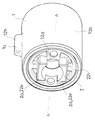
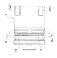
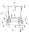
以下、図1〜図15に基づいて、この発明の典型的な実施の形態について、説明する。この実施の形態にかかるダンパー装置は、ステーター1と、ローター2と、これらの間に充填されて前記ローター2の回転又は相対的な回転に抵抗を付与する粘性流体とを備え、この抵抗を制動力とするものであって、いわゆるロータリーダンパーあるいは回転ダンパーなどと称されるものである。かかるステーター1及びローター2は、典型的には、合成樹脂材料から構成される。
Hereinafter, typical embodiments of the present invention will be described with reference to FIGS. The damper device according to this embodiment includes a
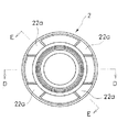
前記ローター2は図示しない一方対象物に対する取付部2aを、ステーター1は図示しない他方対象物に対する取付部1aを、それぞれ備える。そして、かかるダンパー装置は、一方対象物の可動又は相対的な可動によりローター2が回転又は相対的に回転するとき、かかる一方対象物の可動又は相対的な可動に前記粘性流体の抵抗に起因した一定の制動力を作用させるように用いられる。
The
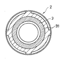
また、この実施の形態にかかるダンパー装置は、軟質合成樹脂よりなる環状シール部3を備えている。かかるダンパー装置は、かかる環状シール部3によって前記ステーター1とローター2との間に充填された粘性流体の漏れ出しを防ぐようになっている。
The damper device according to this embodiment includes an
この実施の形態にかかるダンパー装置にあっては、前記環状シール部3は、二色成形、あるいは、インサート成形により備えられるようになっている。すなわち、前記環状シール部3は、二色成形又はローター2をインサート物としたインサート成形により、このローター2に一体に備えられるようになっている。これにより、この実施の形態にかかるダンパー装置にあっては、前記環状シール部3は、前記ローター2と一体でその一部となることから、ダンパー装置の部品点数は最小化される。また、ダンパー装置をアッセンブリーする際に、環状シール部3のセットが必要ない。
In the damper device according to this embodiment, the
また、前記環状シール部3は、前記ローター2の回転軸x(図3参照)方向に突き出す部分3aを、その成形にあたり備えるようになっている。前記ローター2は、前記環状シール部3の成形時に、この環状シール部3に前記突き出す部分3aを備えさせるための凹み5を備えたものとなっている。これにより、この実施の形態にかかるダンパー装置にあっては、前記環状シール部3は、前記凹み5に前記ローター2の回転軸方向に突き出す部分3aをはめ込んだような態様で前記ローター2と強固に一体化され、かかる環状シール部3を単純なリング状部とした場合のように前記アッセンブリーの際にこのリング状部が捩れるなどしてかかるアッセンブリーを円滑に行ない難くするといった不都合は防止される。
Further, the
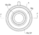
また、この実施の形態にあっては、前記ステーター1は前記粘性流体の充填される環状空間12gを有し、前記ローター2の主体部はこの環状空間12gに収まるようになっている。それと共に、前記環状シール部3は、前記ローター2の外周部22nに備えられる外側環状部分32と、前記ローター2の内周部22mに備えられる内側環状部分31と、両者の連結部分33とを備えた構成となっている。
In this embodiment, the
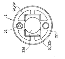
ローター2は筒両端を共に開放させた円筒状を呈している。ローター2の筒一端には、ローター2の回転軸x(図3参照)を周回する方向において、隣り合う割り欠き部22aとの間に略等しい間隔を開けて四箇所の割り欠き部22aが形成されている。ローター2の筒他端側には、この筒他端側においてローター2の内径を小さくさせる内鍔部22bが形成されており、この内鍔部22bによりローター2は筒他端側に周回段差面22cを備えている。ローター2はその筒一端側からステーター1の後述の環状空間12gに納め入れられる。ローター2の筒他端には、その筒口22dを挟んだ両側にそれぞれ、凸部22eが形成されている。
The
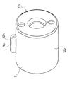
ステーター1は、共に円筒状をなす内筒部12aと外筒部12bとにより内側周回壁12cと外側周回壁12fとを有し、両者の間を環状空間12gとすると共に、外側周回壁12fの外面の一箇所に筒軸方向に沿って延びるリブ12hを有している。
The
図示の例では、ローター2は一方対象物に形成された図示しない凹部に前記凸部22eをはめ込んでこの一方対象物に取り付けられて一方対象物の回動又は相対的な回動に伴って一方対象物と一緒に回動又は相対的に回動するようになっている。一方、ステーター1は、他方対象物に形成された図示しない凹部に前記リブ12hをはめ込んで他方対象物側と一体化されるようになっている。すなわち、図示の例では、ローター2の凸部22eが一方対象物への取付部2aとして機能し、ステーター1のリブ12hが他方対象物への取付部1aとして機能するようになっている。
In the illustrated example, the
ステーター1は、前記内側周回壁12cと外側周回壁12fと底壁12iとを有し、これらの壁12c、12f、12iによって前記底壁12i側と反対の導入開口12jより前記ローター2をその開放端側から回転又は相対的な回転可能に納め入れ可能な有底の環状空間12gを備えている。底壁12iは、前記内筒部12aの筒一端と外筒部12bの筒一端との間に亘る底板によって形成されている。図示を省略する粘性流体は、かかる前記環状空間12gに充填されて前記一方対象物の可動又は相対的な可動に伴うローター2の回転又は相対的な回転に抵抗を付与する。かかる粘性流体としては、典型的には、シリコンオイルやグリスオイルを用いることができる。すなわち、外側周回壁12fと内側周回壁12cとの間には、ローター2の肉厚よりもやや大きい間隔が形成されている。
The
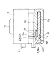
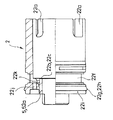
ローター2の筒他端側であってローター2の外周部22nには、この筒他端との間にやや間隔を開けるようにして、周回溝22fが形成されている。また、ローター2の筒他端とこの周回溝22fとの間には、ローター2の外周部22nにおいて、ステーター1の環状空間12gにローター2を入れ込みきった位置でステーター1の外側周回壁12fにおける導入開口12j側に形成された被係合部12kに係合される係合部22gが形成されている。かかる係合部22gは、周回凸部22hとして構成されている。また、かかる被係合部12kは、ステーター1の外筒部12bの導入開口12j側の内面に形成された周回凹部12mとして構成されている。ローター2のステーター1への前記納め入れ時には、外筒部12bの筒他端が周回凸部22hに当たって主としてこの外筒部12bの筒他端側が外側に弾性的に押し広げられてこの納め入れを許容すると共に、この納め入れの終了位置での弾性復帰により周回凸部22hは周回凹部12mに入り込み、これによりローター2とステーター1との前記組み合わせ状態が維持されるようになっている。この実施の形態にあっては、前記ローター2の筒他端が、ステーター1の導入開口12jを塞ぐキャップ部22iとして機能し、このキャップ部22i以外の箇所がローター2の主体部として機能するようになっている。
A
前記周回段差面22cには前記凹み5として機能する周回凹所52aが形成されている。ローター2のキャップ部22iには、筒口22dの側方に第一貫通穴22jが形成されている。この第一貫通穴22jは、ローター2の外側と、かかる周回段差面22cにおける周回凹所52aとローター2の内周部22mとの間となる箇所とを連絡するようになっている。また、ローター2のキャップ部22i側の側部には、ローター2の内外を連通する第二貫通穴22kが形成されている、この第二貫通穴22kは、ローター2の直径方向両側にそれぞれ形成されており、前記周回溝22fの溝底に通じている。
A circumferential recess 52a that functions as the recess 5 is formed in the
この実施の形態にあっては、第一に、前記第一貫通穴22jを通じて環状シール部3を構成する軟質の合成樹脂を導いて、ローター2の内周部22mに前記内側環状部分31を形成するようになっている。また、第二に、前記第二貫通穴22kを通じて前記合成樹脂をローター2の外周部22n側に導いて、この外周部22nに前記外側環状部分32を形成するようになっている。前記連結部分33はかかる第二貫通穴22k内に形成されることとなり、外側環状部分32と内側環状部分31とは環状シール部3の直径方向両側においてそれぞれ連結部分33により連結された態様となっている。
In this embodiment, first, the inner
図10に示されるように、前記内側環状部分31は、前記キャップ部22i側に位置される一端31aを前記周回段差面22cに密着させ、その外周面31bをローター2の内周部22mに密着させた短寸円筒状を呈している。この内側環状部分31の一端31aには、前記周回凹所52aによって、前記ローター2の回転軸x方向に突き出す部分3aが周回状に備えられている。内側環状部分31の他端31c側においては、内側環状部分31の内周面31dはこの他端31cに近づくに連れて内側環状部分31の肉厚を段階的に薄くするように形成されている。内側環状部分31のその余の内周面31dは前記周回状に突き出す部分3aの内周面と同面をなしローター2の回転軸x(図3参照)と実質的に平行である。
As shown in FIG. 10, the inner
前記外側環状部分32は、前記周回溝22fを埋める周回帯状の基部32aと、この基部32aと一体をなす断面半円弧状の周回隆起部32bとを備えた構成となっている。
The outer
前記連結部分33は、前記第二貫通穴22kによって形成され、前記内側環状部分31と外側環状部分32とは、環状シール部3の直径方向両側においてそれぞれかかる連結部分33によって連結されている。
The connecting
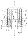
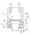
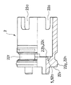
この実施の形態にあっては、ステーター1の内筒部12aにおける前記導入開口12j側に位置される端部12dがローター2の前記周回段差面22cに突き当たる位置までステーター1内にローター2の主体部が入れ込まれると、前記係合部22gと被係合部12kとが係合されると共に、前記内側環状部分31の内周面31dによってステーター1の内筒部12aの内面となる前記内側周回壁12cとローター2の内周部22mとの間がシールされ、かつ、前記外側環状部分32の周回隆起部32bによってステーター1の外筒部12bの外面となる前記外側周回壁12fとローター2の外周部22nとの間がシールされるようになっている。この実施の形態にあっては、ステーター1の内筒部12aとローター2の内鍔部22bの内方とが、これらの間にシャフトを挿通できるように、連通される構成となっている。かかる内側環状部分31と外側環状部分32とは、前記ローター2を貫通する連結部分33によって一体化されていることから(図3)、ステーター1とローター2とのアッセンブリーに際し内側環状部分31と外側環状部分32は捩れたりズレたりすることなく、かかるアッセンブリーはスムースになすことができる。
In this embodiment, the main body of the
また、この実施の形態にあっては、前記ステーター1の環状空間12gを構成する前記内側周回壁12cに、前記環状シール部3の内側環状部分31に前記連結部分33の形成位置において当接される環状突部12nが形成されている。図示の例では、前記内筒部12aは、前記周回段差面22cに突き当たる端部12dを開放させていると共に、この端部12d側を、この端部側の外径をその余の箇所よりも小さくさせる薄肉部12eとしている。そして、この薄肉部12eに前記環状突部12nを備えるようになっている。前記連結部分33の形成箇所において環状シール部3の径方向の肉厚y(図3参照)はその余の箇所の径方向の肉厚よりも大きくなるため、この連結部分33の形成箇所には成形後の収縮による「ひけ」が少なからず生じるが、前記環状突部12nによりかかる「ひけ」が生じても前記形成箇所における内側環状部分31及び外側環状部分32のシール性が低下しないようにすることができる。
In this embodiment, the inner
なお、当然のことながら、本発明は以上に説明した実施態様に限定されるものではなく、本発明の目的を達成し得るすべての実施態様を含むものである。 Of course, the present invention is not limited to the embodiments described above, but includes all embodiments that can achieve the object of the present invention.
1 ステーター
12g 環状空間
2 ローター
22m 内周部
22n 外周部
3 環状シール部
31 内側環状部分
32 外側環状部分
33 連結部分
DESCRIPTION OF
Claims (3)
前記ローターに、軟質合成樹脂よりなる環状シール部を一体成形により備えさせてなると共に、
前記ステーターは前記粘性流体の充填される環状空間を有し、前記ローターの主体部はこの環状空間に収まるようになっており、
前記環状シール部は、前記ローターの外周部に備えられる外側環状部分と、前記ローターの内周部に備えられる内側環状部分と、両者の連結部分とを備えた構成となっている、ダンパー装置。 A damper device comprising a stator, a rotor, and a viscous fluid that is filled between the stator and imparts resistance to rotation or relative rotation of the rotor, and uses this resistance as a braking force,
The rotor is provided with an annular seal portion made of a soft synthetic resin by integral molding,
The stator has an annular space filled with the viscous fluid, and the main part of the rotor is adapted to be accommodated in the annular space.
The said annular seal part is a damper apparatus comprised with the outer side annular part with which the outer peripheral part of the said rotor is equipped, the inner side annular part with which the inner peripheral part of the said rotor is provided, and a connection part of both.
Priority Applications (5)
| Application Number | Priority Date | Filing Date | Title |
|---|---|---|---|
| JP2014018924A JP6150737B2 (en) | 2014-02-03 | 2014-02-03 | Damper device |
| EP15743555.3A EP3106707B1 (en) | 2014-02-03 | 2015-01-28 | Damper device |
| PCT/JP2015/052368 WO2015115487A1 (en) | 2014-02-03 | 2015-01-28 | Damper device |
| CN201580007077.4A CN105980729B (en) | 2014-02-03 | 2015-01-28 | Damping unit |
| US15/115,786 US9909637B2 (en) | 2014-02-03 | 2015-01-28 | Damper device |
Applications Claiming Priority (1)
| Application Number | Priority Date | Filing Date | Title |
|---|---|---|---|
| JP2014018924A JP6150737B2 (en) | 2014-02-03 | 2014-02-03 | Damper device |
Publications (2)
| Publication Number | Publication Date |
|---|---|
| JP2015145705A JP2015145705A (en) | 2015-08-13 |
| JP6150737B2 true JP6150737B2 (en) | 2017-06-21 |
Family
ID=53757060
Family Applications (1)
| Application Number | Title | Priority Date | Filing Date |
|---|---|---|---|
| JP2014018924A Active JP6150737B2 (en) | 2014-02-03 | 2014-02-03 | Damper device |
Country Status (5)
| Country | Link |
|---|---|
| US (1) | US9909637B2 (en) |
| EP (1) | EP3106707B1 (en) |
| JP (1) | JP6150737B2 (en) |
| CN (1) | CN105980729B (en) |
| WO (1) | WO2015115487A1 (en) |
Families Citing this family (2)
| Publication number | Priority date | Publication date | Assignee | Title |
|---|---|---|---|---|
| JP6262488B2 (en) * | 2013-10-10 | 2018-01-17 | 株式会社パイオラックス | Damper and handle device including the same |
| JP6359441B2 (en) * | 2014-12-16 | 2018-07-18 | 株式会社ニフコ | Damper manufacturing method |
Family Cites Families (20)
| Publication number | Priority date | Publication date | Assignee | Title |
|---|---|---|---|---|
| JPS59100128U (en) * | 1982-12-23 | 1984-07-06 | 株式会社ニフコ | oil damper |
| JP2527937B2 (en) * | 1986-06-16 | 1996-08-28 | エヌオーケー株式会社 | Oil seal manufacturing method |
| JPH0742999B2 (en) * | 1986-08-05 | 1995-05-15 | 株式会社ニフコ | Oil type damper |
| SU1634862A2 (en) * | 1988-10-14 | 1991-03-15 | Rakhmanov Nikolaj N | Elastic hydraulic member |
| SE509769C2 (en) * | 1993-09-03 | 1999-03-08 | Itw Ateco Gmbh | rotational dampers |
| DE4413325C2 (en) | 1994-04-16 | 2001-03-15 | Itw Ateco Gmbh | Rotary damper |
| DE60036740T2 (en) * | 1999-08-05 | 2008-02-07 | Nifco Inc., Yokohama | Cylindrical rotary damper with oil |
| TW528129U (en) | 1999-08-09 | 2003-04-11 | Nifco Inc | Oil type cylindrical rotary damper |
| JP4524771B2 (en) * | 2001-01-26 | 2010-08-18 | 株式会社ニフコ | Rotating damper and assist grip device |
| JP3994769B2 (en) * | 2002-03-22 | 2007-10-24 | 東海ゴム工業株式会社 | Suspension upper mount |
| US6866588B2 (en) * | 2002-06-11 | 2005-03-15 | Illinois Tool Works Inc. | One-way damper |
| JP2006242373A (en) * | 2004-09-24 | 2006-09-14 | Nok Corp | Sealing device |
| JP2008115881A (en) * | 2006-10-31 | 2008-05-22 | Hitachi Ltd | Cylinder device |
| ES1064391Y (en) | 2006-12-13 | 2007-06-01 | Pladomin S A | SHOCK ABSORBER DEVICE |
| EP1939485B1 (en) * | 2006-12-29 | 2010-11-10 | Aktiebolaget SKF | A hydraulic sealing and guide unit for a rod of a one-pipe shock absorber |
| WO2009084055A1 (en) | 2007-12-31 | 2009-07-09 | Antonino Cultraro | A rotary damper having improved braking features |
| JP5743557B2 (en) * | 2011-01-11 | 2015-07-01 | 株式会社ニフコ | Damper device |
| JP5756392B2 (en) * | 2011-11-01 | 2015-07-29 | カヤバ工業株式会社 | Sealing device and shock absorber provided with the sealing device |
| CN202876982U (en) | 2012-11-11 | 2013-04-17 | 浙江荣鹏气动工具有限公司 | Spray tip structure of electrostatic spray gun |
| CN203384365U (en) | 2013-07-30 | 2014-01-08 | 宁波兰迪汽配工业有限公司 | Waterproof sealing structure with integration between plastic fastener and sealing ring |
-
2014
- 2014-02-03 JP JP2014018924A patent/JP6150737B2/en active Active
-
2015
- 2015-01-28 EP EP15743555.3A patent/EP3106707B1/en active Active
- 2015-01-28 US US15/115,786 patent/US9909637B2/en active Active
- 2015-01-28 WO PCT/JP2015/052368 patent/WO2015115487A1/en not_active Ceased
- 2015-01-28 CN CN201580007077.4A patent/CN105980729B/en active Active
Also Published As
| Publication number | Publication date |
|---|---|
| EP3106707B1 (en) | 2019-06-19 |
| EP3106707A4 (en) | 2017-11-29 |
| JP2015145705A (en) | 2015-08-13 |
| CN105980729A (en) | 2016-09-28 |
| WO2015115487A1 (en) | 2015-08-06 |
| EP3106707A1 (en) | 2016-12-21 |
| CN105980729B (en) | 2018-01-23 |
| US9909637B2 (en) | 2018-03-06 |
| US20170009838A1 (en) | 2017-01-12 |
Similar Documents
| Publication | Publication Date | Title |
|---|---|---|
| WO2015190381A1 (en) | Fluid damper device and machine equipped with damper | |
| JP6150737B2 (en) | Damper device | |
| JP5743557B2 (en) | Damper device | |
| JP6400932B2 (en) | Fluid damper device and damper equipped device | |
| JP5738656B2 (en) | damper | |
| JP2017061960A (en) | Flow passage selector valve | |
| JP6210893B2 (en) | Damper device | |
| EP2551566B1 (en) | Rotary valve and rotary valve seal | |
| JP2020159441A (en) | Three-way valve | |
| CN111350844B (en) | Ball valve | |
| JP7152341B2 (en) | rotary switching valve | |
| JP2020159440A (en) | Revolver switching valve | |
| JP2013019444A (en) | Rotating damper | |
| JP4898629B2 (en) | Damper device | |
| WO2017130847A1 (en) | Fluid damper device and apparatus with damper | |
| JP2015194231A (en) | Fluid damper device and apparatus with damper | |
| JP2015108445A (en) | Sealing device | |
| JP2012102827A (en) | Rotary damper | |
| JP6487707B2 (en) | Fluid damper device and damper equipped device | |
| JP2019100402A (en) | Fluid damper device | |
| WO2017130848A1 (en) | Fluid damper device and apparatus with damper | |
| JP5469772B2 (en) | Rotary damper | |
| JP2008196585A (en) | Sealing device | |
| JP2015098899A (en) | Connection structure of fluid channel, and sealing device used therefor | |
| WO2019130882A1 (en) | Material container and magnetic heat pump device |
Legal Events
| Date | Code | Title | Description |
|---|---|---|---|
| A621 | Written request for application examination |
Free format text: JAPANESE INTERMEDIATE CODE: A621 Effective date: 20160720 |
|
| TRDD | Decision of grant or rejection written | ||
| A01 | Written decision to grant a patent or to grant a registration (utility model) |
Free format text: JAPANESE INTERMEDIATE CODE: A01 Effective date: 20170516 |
|
| A61 | First payment of annual fees (during grant procedure) |
Free format text: JAPANESE INTERMEDIATE CODE: A61 Effective date: 20170523 |
|
| R150 | Certificate of patent or registration of utility model |
Ref document number: 6150737 Country of ref document: JP Free format text: JAPANESE INTERMEDIATE CODE: R150 |
|
| R250 | Receipt of annual fees |
Free format text: JAPANESE INTERMEDIATE CODE: R250 |
|
| R250 | Receipt of annual fees |
Free format text: JAPANESE INTERMEDIATE CODE: R250 |
|
| R250 | Receipt of annual fees |
Free format text: JAPANESE INTERMEDIATE CODE: R250 |
|
| R250 | Receipt of annual fees |
Free format text: JAPANESE INTERMEDIATE CODE: R250 |
|
| R250 | Receipt of annual fees |
Free format text: JAPANESE INTERMEDIATE CODE: R250 |
|
| R250 | Receipt of annual fees |
Free format text: JAPANESE INTERMEDIATE CODE: R250 |