JP6149311B2 - Burner module, method of forming glass plate, and glass plate formed by this method - Google Patents
Burner module, method of forming glass plate, and glass plate formed by this method Download PDFInfo
- Publication number
- JP6149311B2 JP6149311B2 JP2015515135A JP2015515135A JP6149311B2 JP 6149311 B2 JP6149311 B2 JP 6149311B2 JP 2015515135 A JP2015515135 A JP 2015515135A JP 2015515135 A JP2015515135 A JP 2015515135A JP 6149311 B2 JP6149311 B2 JP 6149311B2
- Authority
- JP
- Japan
- Prior art keywords
- burner
- gas
- flow plate
- inlet
- channel
- Prior art date
- Legal status (The legal status is an assumption and is not a legal conclusion. Google has not performed a legal analysis and makes no representation as to the accuracy of the status listed.)
- Expired - Fee Related
Links
- 239000011521 glass Substances 0.000 title claims description 69
- 238000000034 method Methods 0.000 title claims description 37
- 239000007789 gas Substances 0.000 claims description 227
- 239000004071 soot Substances 0.000 claims description 82
- 239000002243 precursor Substances 0.000 claims description 33
- 238000005192 partition Methods 0.000 claims description 27
- 239000006185 dispersion Substances 0.000 claims description 24
- 238000000151 deposition Methods 0.000 claims description 23
- 239000000567 combustion gas Substances 0.000 claims description 20
- 230000008021 deposition Effects 0.000 claims description 19
- 239000002245 particle Substances 0.000 claims description 19
- 238000009826 distribution Methods 0.000 claims description 18
- 239000011261 inert gas Substances 0.000 claims description 18
- 239000007800 oxidant agent Substances 0.000 claims description 18
- 238000004891 communication Methods 0.000 claims description 16
- 230000001590 oxidative effect Effects 0.000 claims description 16
- 230000008569 process Effects 0.000 claims description 15
- 239000012530 fluid Substances 0.000 claims description 14
- 238000002485 combustion reaction Methods 0.000 claims description 8
- 238000005245 sintering Methods 0.000 claims description 8
- 238000005229 chemical vapour deposition Methods 0.000 claims description 3
- 238000010438 heat treatment Methods 0.000 claims description 2
- 239000000203 mixture Substances 0.000 description 13
- VYPSYNLAJGMNEJ-UHFFFAOYSA-N Silicium dioxide Chemical compound O=[Si]=O VYPSYNLAJGMNEJ-UHFFFAOYSA-N 0.000 description 12
- 239000000463 material Substances 0.000 description 8
- VNWKTOKETHGBQD-UHFFFAOYSA-N methane Chemical compound C VNWKTOKETHGBQD-UHFFFAOYSA-N 0.000 description 8
- 239000002019 doping agent Substances 0.000 description 7
- 238000003754 machining Methods 0.000 description 6
- 238000004519 manufacturing process Methods 0.000 description 6
- QVGXLLKOCUKJST-UHFFFAOYSA-N atomic oxygen Chemical compound [O] QVGXLLKOCUKJST-UHFFFAOYSA-N 0.000 description 5
- 239000001301 oxygen Substances 0.000 description 5
- 229910052760 oxygen Inorganic materials 0.000 description 5
- 239000000376 reactant Substances 0.000 description 4
- 239000000377 silicon dioxide Substances 0.000 description 4
- 229910045601 alloy Inorganic materials 0.000 description 3
- 239000000956 alloy Substances 0.000 description 3
- 230000015572 biosynthetic process Effects 0.000 description 3
- 150000004820 halides Chemical class 0.000 description 3
- HMMGMWAXVFQUOA-UHFFFAOYSA-N octamethylcyclotetrasiloxane Chemical compound C[Si]1(C)O[Si](C)(C)O[Si](C)(C)O[Si](C)(C)O1 HMMGMWAXVFQUOA-UHFFFAOYSA-N 0.000 description 3
- 239000012071 phase Substances 0.000 description 3
- 238000007740 vapor deposition Methods 0.000 description 3
- 229910000984 420 stainless steel Inorganic materials 0.000 description 2
- IJGRMHOSHXDMSA-UHFFFAOYSA-N Atomic nitrogen Chemical compound N#N IJGRMHOSHXDMSA-UHFFFAOYSA-N 0.000 description 2
- GWEVSGVZZGPLCZ-UHFFFAOYSA-N Titan oxide Chemical compound O=[Ti]=O GWEVSGVZZGPLCZ-UHFFFAOYSA-N 0.000 description 2
- 230000008901 benefit Effects 0.000 description 2
- 238000013461 design Methods 0.000 description 2
- 238000009760 electrical discharge machining Methods 0.000 description 2
- 238000003286 fusion draw glass process Methods 0.000 description 2
- 238000000227 grinding Methods 0.000 description 2
- 230000007062 hydrolysis Effects 0.000 description 2
- 238000006460 hydrolysis reaction Methods 0.000 description 2
- 229910052751 metal Inorganic materials 0.000 description 2
- 239000002184 metal Substances 0.000 description 2
- 238000012986 modification Methods 0.000 description 2
- 230000004048 modification Effects 0.000 description 2
- 229910001392 phosphorus oxide Inorganic materials 0.000 description 2
- 238000005498 polishing Methods 0.000 description 2
- -1 siloxanes Chemical class 0.000 description 2
- 239000000126 substance Substances 0.000 description 2
- 230000003746 surface roughness Effects 0.000 description 2
- VSAISIQCTGDGPU-UHFFFAOYSA-N tetraphosphorus hexaoxide Chemical compound O1P(O2)OP3OP1OP2O3 VSAISIQCTGDGPU-UHFFFAOYSA-N 0.000 description 2
- OGIDPMRJRNCKJF-UHFFFAOYSA-N titanium oxide Inorganic materials [Ti]=O OGIDPMRJRNCKJF-UHFFFAOYSA-N 0.000 description 2
- VXEGSRKPIUDPQT-UHFFFAOYSA-N 4-[4-(4-methoxyphenyl)piperazin-1-yl]aniline Chemical compound C1=CC(OC)=CC=C1N1CCN(C=2C=CC(N)=CC=2)CC1 VXEGSRKPIUDPQT-UHFFFAOYSA-N 0.000 description 1
- AWVURLDGTPWMMY-UHFFFAOYSA-N CC(C)O.CC(C)O.CC(C)O.P Chemical compound CC(C)O.CC(C)O.CC(C)O.P AWVURLDGTPWMMY-UHFFFAOYSA-N 0.000 description 1
- MYMOFIZGZYHOMD-UHFFFAOYSA-N Dioxygen Chemical compound O=O MYMOFIZGZYHOMD-UHFFFAOYSA-N 0.000 description 1
- 229910000760 Hardened steel Inorganic materials 0.000 description 1
- UFHFLCQGNIYNRP-UHFFFAOYSA-N Hydrogen Chemical compound [H][H] UFHFLCQGNIYNRP-UHFFFAOYSA-N 0.000 description 1
- 229910000990 Ni alloy Inorganic materials 0.000 description 1
- 238000006124 Pilkington process Methods 0.000 description 1
- XUIMIQQOPSSXEZ-UHFFFAOYSA-N Silicon Chemical compound [Si] XUIMIQQOPSSXEZ-UHFFFAOYSA-N 0.000 description 1
- LCKIEQZJEYYRIY-UHFFFAOYSA-N Titanium ion Chemical compound [Ti+4] LCKIEQZJEYYRIY-UHFFFAOYSA-N 0.000 description 1
- 150000004703 alkoxides Chemical class 0.000 description 1
- 238000013459 approach Methods 0.000 description 1
- 230000009286 beneficial effect Effects 0.000 description 1
- 239000012159 carrier gas Substances 0.000 description 1
- 238000004140 cleaning Methods 0.000 description 1
- 239000011246 composite particle Substances 0.000 description 1
- 230000007797 corrosion Effects 0.000 description 1
- 238000005260 corrosion Methods 0.000 description 1
- 238000005520 cutting process Methods 0.000 description 1
- 230000007547 defect Effects 0.000 description 1
- 230000007812 deficiency Effects 0.000 description 1
- 230000002950 deficient Effects 0.000 description 1
- 229910001882 dioxygen Inorganic materials 0.000 description 1
- 238000005553 drilling Methods 0.000 description 1
- 238000011067 equilibration Methods 0.000 description 1
- 239000005329 float glass Substances 0.000 description 1
- 239000005350 fused silica glass Substances 0.000 description 1
- 230000005484 gravity Effects 0.000 description 1
- 238000009499 grossing Methods 0.000 description 1
- 239000001257 hydrogen Substances 0.000 description 1
- 229910052739 hydrogen Inorganic materials 0.000 description 1
- 238000011065 in-situ storage Methods 0.000 description 1
- 238000002955 isolation Methods 0.000 description 1
- 238000011068 loading method Methods 0.000 description 1
- 238000005259 measurement Methods 0.000 description 1
- 230000007246 mechanism Effects 0.000 description 1
- 238000003801 milling Methods 0.000 description 1
- 229910052757 nitrogen Inorganic materials 0.000 description 1
- 230000000737 periodic effect Effects 0.000 description 1
- 238000012545 processing Methods 0.000 description 1
- 229910052761 rare earth metal Inorganic materials 0.000 description 1
- 239000012495 reaction gas Substances 0.000 description 1
- 150000003839 salts Chemical class 0.000 description 1
- 238000007789 sealing Methods 0.000 description 1
- 230000035939 shock Effects 0.000 description 1
- 229910052710 silicon Inorganic materials 0.000 description 1
- 239000010703 silicon Substances 0.000 description 1
- 239000005049 silicon tetrachloride Substances 0.000 description 1
- 239000000758 substrate Substances 0.000 description 1
- 238000004381 surface treatment Methods 0.000 description 1
- 238000007514 turning Methods 0.000 description 1
- 238000005019 vapor deposition process Methods 0.000 description 1
- 239000012808 vapor phase Substances 0.000 description 1
Images


Classifications
-
- C—CHEMISTRY; METALLURGY
- C03—GLASS; MINERAL OR SLAG WOOL
- C03B—MANUFACTURE, SHAPING, OR SUPPLEMENTARY PROCESSES
- C03B19/00—Other methods of shaping glass
- C03B19/06—Other methods of shaping glass by sintering, e.g. by cold isostatic pressing of powders and subsequent sintering, by hot pressing of powders, by sintering slurries or dispersions not undergoing a liquid phase reaction
-
- F—MECHANICAL ENGINEERING; LIGHTING; HEATING; WEAPONS; BLASTING
- F23—COMBUSTION APPARATUS; COMBUSTION PROCESSES
- F23D—BURNERS
- F23D14/00—Burners for combustion of a gas, e.g. of a gas stored under pressure as a liquid
- F23D14/46—Details, e.g. noise reduction means
- F23D14/48—Nozzles
- F23D14/58—Nozzles characterised by the shape or arrangement of the outlet or outlets from the nozzle, e.g. of annular configuration
- F23D14/583—Nozzles characterised by the shape or arrangement of the outlet or outlets from the nozzle, e.g. of annular configuration of elongated shape, e.g. slits
-
- C—CHEMISTRY; METALLURGY
- C03—GLASS; MINERAL OR SLAG WOOL
- C03B—MANUFACTURE, SHAPING, OR SUPPLEMENTARY PROCESSES
- C03B19/00—Other methods of shaping glass
- C03B19/14—Other methods of shaping glass by gas- or vapour- phase reaction processes
-
- C—CHEMISTRY; METALLURGY
- C03—GLASS; MINERAL OR SLAG WOOL
- C03B—MANUFACTURE, SHAPING, OR SUPPLEMENTARY PROCESSES
- C03B19/00—Other methods of shaping glass
- C03B19/14—Other methods of shaping glass by gas- or vapour- phase reaction processes
- C03B19/1415—Reactant delivery systems
- C03B19/1423—Reactant deposition burners
-
- F—MECHANICAL ENGINEERING; LIGHTING; HEATING; WEAPONS; BLASTING
- F23—COMBUSTION APPARATUS; COMBUSTION PROCESSES
- F23D—BURNERS
- F23D14/00—Burners for combustion of a gas, e.g. of a gas stored under pressure as a liquid
-
- C—CHEMISTRY; METALLURGY
- C03—GLASS; MINERAL OR SLAG WOOL
- C03B—MANUFACTURE, SHAPING, OR SUPPLEMENTARY PROCESSES
- C03B2207/00—Glass deposition burners
- C03B2207/02—Elongated flat flame or slit-nozzle type
-
- C—CHEMISTRY; METALLURGY
- C03—GLASS; MINERAL OR SLAG WOOL
- C03B—MANUFACTURE, SHAPING, OR SUPPLEMENTARY PROCESSES
- C03B2207/00—Glass deposition burners
- C03B2207/20—Specific substances in specified ports, e.g. all gas flows specified
-
- C—CHEMISTRY; METALLURGY
- C03—GLASS; MINERAL OR SLAG WOOL
- C03B—MANUFACTURE, SHAPING, OR SUPPLEMENTARY PROCESSES
- C03B2207/00—Glass deposition burners
- C03B2207/30—For glass precursor of non-standard type, e.g. solid SiH3F
- C03B2207/34—Liquid, e.g. mist or aerosol
-
- C—CHEMISTRY; METALLURGY
- C03—GLASS; MINERAL OR SLAG WOOL
- C03B—MANUFACTURE, SHAPING, OR SUPPLEMENTARY PROCESSES
- C03B2207/00—Glass deposition burners
- C03B2207/42—Assembly details; Material or dimensions of burner; Manifolds or supports
-
- F—MECHANICAL ENGINEERING; LIGHTING; HEATING; WEAPONS; BLASTING
- F23—COMBUSTION APPARATUS; COMBUSTION PROCESSES
- F23D—BURNERS
- F23D2900/00—Special features of, or arrangements for burners using fluid fuels or solid fuels suspended in a carrier gas
- F23D2900/21—Burners specially adapted for a particular use
- F23D2900/21005—Burners specially adapted for a particular use for flame deposition, e.g. FHD, flame hydrolysis deposition
-
- Y—GENERAL TAGGING OF NEW TECHNOLOGICAL DEVELOPMENTS; GENERAL TAGGING OF CROSS-SECTIONAL TECHNOLOGIES SPANNING OVER SEVERAL SECTIONS OF THE IPC; TECHNICAL SUBJECTS COVERED BY FORMER USPC CROSS-REFERENCE ART COLLECTIONS [XRACs] AND DIGESTS
- Y10—TECHNICAL SUBJECTS COVERED BY FORMER USPC
- Y10T—TECHNICAL SUBJECTS COVERED BY FORMER US CLASSIFICATION
- Y10T428/00—Stock material or miscellaneous articles
- Y10T428/24—Structurally defined web or sheet [e.g., overall dimension, etc.]
- Y10T428/24355—Continuous and nonuniform or irregular surface on layer or component [e.g., roofing, etc.]
Description
本出願は、米国特許法第120条の下で、2012年5月31日出願の米国特許出願第13/484466号の優先権の利益を主張するものであり、本出願は参照により上記出願の内容全体を援用する。 This application claims the benefit of priority of US Patent Application No. 13/484466, filed May 31, 2012, under Section 120 of the US Patent Act, which is incorporated herein by reference. Use the entire contents.
本開示は一般に、薄いガラス板及びガラスリボンに関し、より詳細には、バーナモジュール、ガラス板及びガラスリボンを形成する方法、並びに上記方法により形成されるガラス板及びガラスリボンに関する。 The present disclosure relates generally to thin glass plates and glass ribbons, and more particularly to burner modules, methods of forming glass plates and glass ribbons, and glass plates and glass ribbons formed by the above methods.
ガラス板材料は、例えばフロートガラスプロセス及びフュージョンドロープロセスを含む様々な異なる方法を使用して形成できる。ガラスリボンとは、材料の連続的なスプール処理が可能なほどガラスが薄いことにより、現実的なサイズのロールに巻ける薄さの、ガラス板の下位集合である。フロートガラスはガラスのリボンを作製するには現実的ではなく、一般により厚い板を対象としている。フュージョンドロープロセスはリボンの作製が可能な範囲の薄さに拡張されつつあるが、シリカレベル及び軟化点が高い柔らかいガラス組成物に依然として限られている。更に、シリカガラス基材は、バッチ式火炎加水分解炉で生成されたシリカインゴットを切削し、研削し、研磨することによって製造できるが、これはガラスリボンには実用的ではない。 The glass sheet material can be formed using a variety of different methods including, for example, the float glass process and the fusion draw process. Glass ribbons are a subset of glass plates that are thin enough to be wound on realistic sized rolls because the glass is thin enough to allow continuous spooling of material. Float glass is not practical for making glass ribbons and is generally intended for thicker plates. The fusion draw process is being expanded to the extent that ribbons can be made, but is still limited to soft glass compositions with high silica levels and softening points. Further, silica glass substrates can be manufactured by cutting, grinding and polishing silica ingots produced in a batch flame hydrolysis furnace, which is not practical for glass ribbons.
本発明者らは、上述のプロセスの代替策、より詳細には高い表面品質を有する均一な薄いガラス板及びガラスリボンを形成するための経済的な代替策の必要性を認識している。 The inventors have recognized the need for an alternative to the process described above, more particularly an economical alternative to form uniform thin glass plates and glass ribbons with high surface quality.
本開示は、バーナモジュール、ガラス板及びガラスリボンを形成する方法、並びに上記方法によって形成されるガラス板及びガラスリボン製品を紹介する。 The present disclosure introduces a method of forming a burner module, a glass plate and a glass ribbon, and a glass plate and a glass ribbon product formed by the above method.
本開示の特定の実施形態によると、バーナガス入口ブロック、下部フロープレート、上部フロープレート、バーナガス流分散器及びバーナガス放出ブロックを備える、バーナモジュールが提供される。バーナガス入口ブロック、バーナガス流分散器及びバーナガス放出ブロックの各々は、仕切りで区切られた複数のチャネルを備える。バーナガス流分散器及びバーナガス放出ブロックの仕切りはナイフエッジを備える。上部フロープレート及び下部フロープレートはそれぞれ、複数のチャネルと流体連通する複数の圧力孔を備える。 According to certain embodiments of the present disclosure, a burner module is provided that includes a burner gas inlet block, a lower flow plate, an upper flow plate, a burner gas flow distributor, and a burner gas discharge block. Each of the burner gas inlet block, the burner gas flow distributor, and the burner gas discharge block includes a plurality of channels separated by partitions. The burner gas flow distributor and the burner gas discharge block partition comprise knife edges. Each of the upper and lower flow plates includes a plurality of pressure holes in fluid communication with the plurality of channels.
本開示の更なる実施形態によると、ガラス板及びガラスリボンを形成する方法が提供され、本方法は、開示されたバーナモジュールを介して生成される複数のガラススート粒子を回転式ドラムの蒸着面に蒸着してスートシートを形成するステップ、回転式ドラムの蒸着面からスートシートの少なくとも一部を取り外すステップ、及び移動するスートシートの一部を焼結温度に加熱することによってスートシートの少なくとも一部を焼結して高密度化ガラスとするステップを含む。 According to a further embodiment of the present disclosure, a method of forming a glass plate and a glass ribbon is provided, the method comprising a plurality of glass soot particles generated via the disclosed burner module for depositing a rotary drum deposition surface. Depositing at least one part of the soot sheet from the deposition surface of the rotary drum, and heating at least one part of the moving soot sheet to a sintering temperature. Sintering the part to a densified glass.
本開示のまた更なる実施形態によると、開示されたバーナモジュールを用いて製造されるガラス板及びガラスリボン製品が期待される。 According to still further embodiments of the present disclosure, glass sheets and glass ribbon products manufactured using the disclosed burner module are expected.
本発明の更なる特徴及び利点について、以下の詳細な説明で詳細に述べるが、上記特徴及び利点の一部は、この詳細な説明から当業者には容易に明らかになり、又は以下の詳細な説明、請求項及び添付の図面を含む本出願に記載された様々な実施形態を実施することにより把握できるであろう。 Additional features and advantages of the present invention will be described in detail in the following detailed description, some of which are readily apparent to those skilled in the art from this detailed description, or described in detail below. It will be understood by implementing various embodiments described in this application, including the description, claims and accompanying drawings.
本開示の具体的実施形態に関する以下の詳細な説明は、以下の図面と関連付けて読んだ場合に最もよく理解できるものである。これら図面においては、同様の構造は同様の参照番号で示されている。 The following detailed description of specific embodiments of the present disclosure is best understood when read in conjunction with the following drawings. In these drawings, like structures are indicated with like reference numerals.
図面全体、及び特に図1を参照すると、図が本発明の特定の実施形態を説明することを目的としたものであり、本発明を上記特定の実施形態に限定することを目的としたものではないことが理解される。 With reference to the entire drawing and in particular with reference to FIG. 1, the figures are for the purpose of illustrating particular embodiments of the invention and are not intended to limit the invention to the specific embodiments described above. It is understood that there is no.
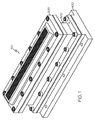
図1、2を参照すると、バーナモジュールの組み立て状態及び分解状態の概略図が示されている。バーナモジュール100は、バーナガス放出ブロック200、バーナガス流分散器300、バーナガス入口ブロック400、上部フロープレート500及び下部フロープレート600を備える。用語「上部」及び「下部」は単に上部フロープレート500及び下部フロープレート600を区別するために使用されており、フロープレートの相対的な位置を限定するために使用されるのではない。というのは、バーナモジュール100は多くの配向で使用され得るためである。
Referring to FIGS. 1 and 2, schematic views of the burner module assembled and disassembled are shown. The
図2、3を参照すると、バーナガス放出ブロック200は、バーナガス放出ブロックのバーナ面204に位置する複数の開口202を備える。バーナガス放出ブロック200は、ガス放出チャネル仕切り208によって区切られた複数のガス放出チャネル206を更に備える。ガス放出チャネル206は、バーナガス放出ブロック210の入口面から複数のバーナ面チャネル212まで延在する。バーナ面チャネル212は、ガス放出チャネル206からバーナ面204に位置する開口202まで延在する。ガス放出チャネル仕切り208は、バーナガス放出ブロック210の入口面にナイフエッジ上部フロープレート接触面214を備える。ナイフエッジは、構造物の、幅が縮小された一部分である。
2 and 3, the burner
バーナガス流分散器300は、分散チャネル仕切り304によって区切られた複数の分散チャネル302を備える。分散チャネル302は、バーナガス流分散器306の入口面からバーナガス流分散器308の出口面まで延在する。バーナガス流分散器308の出口面は、ナイフエッジ上部フロープレート接触面214に対するアンビルとして機能する。分散チャネル仕切り304は、バーナガス流分散器306の入口面に、ナイフエッジ下部フロープレート接触面310を備える。
The burner
バーナガス入口ブロック400は、バーナガス入口ブロック404の基部に配置された複数のガス入口402を備える。バーナガス入口ブロック400は、ガス入口チャネル仕切り408によって区切られた複数のガス入口チャネル406を更に備える。ガス入口チャネル406は、バーナガス入口ブロック400のガス入口402からバーナガス入口ブロック410の出口面まで延在する。バーナガス入口ブロック410の出口面は、ナイフエッジ下部フロープレート接触面310に対するアンビルとして機能する。
The burner
図4を参照すると、上部フロープレート500は、長手方向に延在する上部フロープレートランド504によって区切られた複数の上部フロープレート圧力孔502を備える。更に、複数の上部フロープレート圧力孔502はそれぞれ、分散チャネル302のうちの1つ及びガス放出チャネル206のうちの1つと流体連通している。
Referring to FIG. 4, the
下部フロープレート600は、長手方向に延在する下部フロープレートランド604によって区切られた複数の下部フロープレート圧力孔602を備える。更に、複数の下部フロープレート圧力孔602はそれぞれ、ガス入口チャネル406のうちの1つ及び分散チャネル302のうちの1つと流体連通している。
The
バーナモジュール100の一部として、隔離パッケージ(図示せず)を備えてもよい。
An isolation package (not shown) may be provided as part of the
バーナモジュール100はモジュール式設計である。バーナガス放出ブロック200、バーナガス流分散器300、バーナガス入口ブロック400、上部フロープレート500及び下部フロープレート600はそれぞれ、他の構成部品とは独立して交換できる。バーナモジュール100がモジュール式であるという性質は、バーナモジュールの製造中及び適用使用中の両方において有益である。
The
製造段階では、バーナモジュール100全体のうちの単一の部分の小さな欠陥によって組立品全体の廃棄が余儀なくされることはない。残りの構成部品が依然として使用可能な状態で、破損したパーツだけを廃棄できる。更に、バーナモジュール100を複数のセグメントに分けることで、バーナモジュール全体に配置される複数のチャネル、圧力孔及び開口を機械加工する上での困難が軽減される。工具が届かない隠れたチャネルがあるため、従来の機械加工技法を使用してバーナモジュール100の正確な内部幾何学形状を単一の部品として製造することは不可能である。焼結金属又は光硬化金属から他のバーナユニットを製造することによってこの課題を克服しようと試みられてきたが、係る努力はそれ自体が課題及び欠陥を呈している。
In the manufacturing stage, small defects in a single part of the
バーナモジュール100の操作段階の間、バーナモジュール全体に配置される複数のチャネル、圧力孔及び開口を分解してこれらへのアクセスを可能とすることができるため、バーナモジュールの清掃が容易になる。更に、単一の構成部品が何らかの方法で損傷を受けた場合又は破損した場合には、より費用のかかるユニット全体の交換を必要とせずに、その単一の構成部品を交換できる。これは、バーナモジュール100の全ての構成部品の寿命が同一ではない場合に特に都合が良い。
During the operation phase of the
図示したように、これら構成部品は、ボルト800によって単一のバーナモジュール100として組み立てられ、保持されている。ボルト800は、バーナモジュール100の構成部品を一体として密封するのに十分なトルクで締める必要がある。例えば図1に示すようにボルトが12本ある場合にボルト800を締める方法の例は、複数の通路内において指定された順序でボルトを締めることである。バーナ構成要素間の境界面の負荷の均一化を促進するトルク付与シーケンスを使用して、ボルト800を90in−lb(103.680kgf−cm)で締める必要がある。これは好ましくは、各ボルト800を円周順ではない順序で約30in−lb(34.56kgm−cm)で締め、更に各ボルトを約60in−lb(69.12kgm−cm)で締め、最後に更に各ボルトを約90in−lb(103.680kgf−cm)で締めることによって達成される。この手順は、構成部品を一体として接続するボルト800の組それぞれに対して反復できる。個々の構成部品を一体として保持する、リベット等の他の手段も想定される。
As shown, these components are assembled and held as a
図5を参照すると、バーナモジュール100は、バーナ面に近接した燃焼ゾーン内でバーナ火炎を発生させるために、燃焼ガス、酸化剤、スート前駆体及び不活性ガスを、ガス入口402、ガス入口チャネル406、下部フロープレート圧力孔602、分散チャネル302、上部フロープレート圧力孔502、ガス放出チャネル206、複数のバーナ面チャネル212及び複数の開口202を通して化学蒸着プロセスの燃焼場所に送達するように構成されている。
Referring to FIG. 5, the
複数のガス入口402は、少なくとも1つの燃焼ガス入口、少なくとも1つの酸化剤入口、任意に少なくとも1つの不活性ガス入口及び少なくとも1つの前駆体入口を備える。少なくとも1つの燃焼ガス入口は、燃焼ガス源からバーナモジュール100に燃焼ガスを提供し、少なくとも1つの酸化剤入口は、酸化剤源からバーナモジュールに酸化剤を提供し、少なくとも1つの不活性ガス入口は、不活性ガス源からバーナモジュールに不活性ガスを提供し、少なくとも1つの前駆体入口は、スート前駆体源からバーナモジュールにスート前駆体を提供する。
The plurality of
例示的な燃焼ガスは、メタン及び水素を含む。例示的な酸化剤ガスは酸素である。例示的な不活性ガスは窒素である。いくつかの実施形態では、燃焼ガスを酸素と予備混合してよい。様々なケイ素含有前駆体物質を前駆体ガスとして使用してよい。係る前駆体物質としては:四塩化ケイ素等のハロゲン化物を含有する前駆体;及び例えばシロキサン、特にオクタメチルシクロテトラシロキサン(OMCT)といったポリアルキルシロキサン等の、ハロゲン化物を含有しない前駆体を含むが、これらに限定されるものではない。更に、適切なドーパントを使用してよい。これらのドーパントは、前駆体ガスと共にバーナモジュール100に送達できる。あるいは、別個のガス入口402を通してドーパントをバーナモジュール100に送達し、別個の開口202又は開口のアレイを通してバーナモジュール100からドーパントを出してよい。
Exemplary combustion gases include methane and hydrogen. An exemplary oxidant gas is oxygen. An exemplary inert gas is nitrogen. In some embodiments, the combustion gas may be premixed with oxygen. A variety of silicon-containing precursor materials may be used as the precursor gas. Such precursor materials include: precursors containing halides such as silicon tetrachloride; and precursors containing no halides such as siloxanes, especially polyalkylsiloxanes such as octamethylcyclotetrasiloxane (OMCT). However, it is not limited to these. In addition, suitable dopants may be used. These dopants can be delivered to the
図6を参照すると、ある実施形態では、バーナガス入口ブロック400は、各ガス入口チャネル406の長さ約8インチ(20.32センチメートル)に対して5つのガス入口402を備える。あるいはバーナガス入口ブロック400は、各ガス入口チャネル406の基部に配置される3〜7つのガス入口402を備えてよい。各ガス入口チャネル406に配置される個々のガス入口402は、同じ単一の入力ガス又は入力ガスの混合物を提供する。例えば、メタン等の燃焼ガスを含有する所定のガス入口チャネル406は、全てがメタンを提供する3つから7つのガス入口402によって供給を受ける。各ガス入口チャネル406全体にガス入口402を分散させることで、各ガス入力チャネルにわたって、単一のガス入口によって各チャネルに供給するよりも均一にガスを分配できる。
Referring to FIG. 6, in one embodiment, the burner
個々のガス入口402は、各ガス入口チャネル406に予備混合ガスを供給してもよい。例えば、燃焼ガスはメタン及び酸素を含んでよく、又はスート前駆体及び不活性ガスを予備混合して個々のガス入口402に供給してよい。ある実施形態では、燃焼ガス源、酸化剤源、不活性ガス源及び/又はスート前駆体源は、少なくとも2つの入力媒体の混合物を含む。入力媒体は、燃焼ガス、酸化剤、スート前駆体及び不活性ガスを含む。
バーナガス放出ブロック200を更に詳細に調べると、開口202はバーナ面204全体に亘るアレイとして配設され、バーナモジュール100の長さ及び幅全体に亘る燃焼ゾーンへの反応ガスの流れを平衡化する。結果として、燃焼ゾーン内部の火炎が均一になり、蒸着面上でのスートの均一な分散が得られる。バーナモジュール100の長さ及び幅全体に亘る反応ガスの流れの平衡化は、バーナガス流分散器300、バーナガス入口ブロック400、上部フロープレート500及び下部フロープレート600を備える、バーナガス放出ブロック200の前に反応ガスを分散するバーナガスモジュールの他の構成部品の結果でもあることが留意されるべきである。
Examining the burner
開口202のアレイは、配置、サイズ等が事前に選択された所定数の開口をそれぞれ有する、個々のサブアレイを含んでよい。例えば、開口202のアレイは、燃焼ガス用の開口のアレイ、酸化剤用の開口のアレイ、前駆体ガス用の開口のアレイ及び不活性ガス用のアレイを含んでよく、各アレイは異なる開口配置、サイズ等を有する。図1、2に図示した開口202の構成は単一の実施形態にすぎないこと、及び他の構成も可能であり、本開示の範囲内にあることが理解されるべきである。例えば図1、2は、燃焼ガス用の開口のアレイと、酸化剤用の開口のアレイと、前駆体ガス用の開口のアレイと、不活性ガス用の開口のアレイとの間での開口202の一貫した配置を示しているが、サブアレイのいずれかが他のサブアレイよりも多い又は少ない開口若しくは開口の横列を有してよい。
The array of
ある特定の実施形態では、開口202の全体的なアレイは、n本の平行な縦列に配列された複数の開口を備え、nは少なくとも5である。例示的なバーナモジュール100は、開口202の9本の縦列を備える。平行な縦列のアレイは長さl、幅wを有し、この幅wは、アレイの対向する外縁上に配置された開口の外縁間の距離によって定義される。ある実施形態によると、例えばシリカガラススートを形成する際、中心線の縦列(例えば縦列5)はシリカガス前駆体/キャリヤガスの混合物を提供する。すぐ隣の縦列(例えば縦列4及び6)は、シリカガス前駆体のストイキオメトリーの制御のために酸素ガスを提供する。中心線の両側のガスオリフィスの次の2つの縦列(例えば縦列2、3、7、8)は追加の酸素(この追加の酸素の流量によってストイキオメトリー及びスート密度を制御できる)を提供し、また点火火炎に酸化剤を提供する。オリフィスの一番外側の縦列(例えば縦列1、9)は、例えばCH4/O2又はH2/O2といった点火火炎混合物を提供できる。
In certain embodiments, the overall array of

ある選択的な実施形態では、開口202の9本の縦列を備える例示的なバーナモジュール100に応じて、バーナガス入口ブロック400は9つのガス入口チャネル406を備え、バーナガス流分散器300は9つの分散チャネル302を備え、バーナガス放出ブロック200は9つのガス放出チャネル206を備える。
In an optional embodiment, burner
ナイフエッジ下部フロープレート接触面310及びナイフエッジ上部フロープレート接触面214はそれぞれナイフエッジ幅を含み、分散チャネル仕切り304及びガス放出チャネル仕切り208はそれぞれチャネル仕切り幅を含み、チャネル仕切り幅はナイフエッジ幅よりも大きい。好ましくは、ナイフエッジ幅は約0.005インチ(0.0127センチ)から約0.031インチ(0.07874センチ)である。より好ましくは、ナイフエッジ幅は約0.010インチ(0.0254センチ)から約0.015インチ(0.0381センチ)である。更に好ましくは、ナイフエッジ幅は約0.012インチ(0.03048センチ)から約0.013インチ(0.03302センチ)である。好ましくは、チャネル仕切り幅は約0.04インチ(0.1016センチ)から約0.08インチ(0.2032センチ)である。より好ましくは、チャネル仕切り幅は約0.05インチ(0.127センチ)から約0.07インチ(0.1778センチ)である。
The knife edge lower flow
ある選択的な実施形態では、ナイフエッジ下部フロープレート接触面310及びナイフエッジ上部フロープレート接触面214は、切頭三角柱である。
In an optional embodiment, knife edge lower flow
ある実施形態では、バーナガス流分散器300のナイフエッジ下部フロープレート接触面310とバーナガス入口ブロック410の出口面との間に、下部フロープレート600によってシールが形成される。バーナモジュール100を組み立てる際、バーナガス流分散器300のナイフエッジ下部フロープレート接触面310は、下部フロープレート600の下部フロープレートランド604と一致する。ナイフエッジ下部フロープレート接触面310と下部フロープレートランド604との境界面がシールを形成する。更に、下部フロープレート600の平面とバーナガス入口ブロック410の出口面との間に追加のシールが形成される。バーナガス流分散器300のナイフエッジ下部フロープレート接触面310と、下部フロープレート600の下部フロープレートランド604と、バーナガス入口ブロック410の出口面との間のシールは、好ましくは最大で少なくとも15psig(0.1035MPa)、より好ましくは最大で30psig(0.207MPa)で密封できる。
In some embodiments, a seal is formed by the
ある実施形態では、バーナガス放出ブロック200のナイフエッジ上部フロープレート接触面214とバーナガス流分散器308の出口面との間に、上部フロープレート500によってシールが形成される。バーナモジュール100を組み立てる際、バーナガス放出ブロック200のナイフエッジ上部フロープレート接触面214は、上部フロープレート500の上部フロープレートランド504と一致する。ナイフエッジ上部フロープレート接触面214及び上部フロープレートランド504との境界面がシールを形成する。更に、上部フロープレート500の平面とバーナガス流分散器308の出口面との間に追加のシールが形成される。バーナガス放出ブロック200のナイフエッジ上部フロープレート接触面214と、上部フロープレート500の上部フロープレートランド504と、バーナガス流分散器308の出口面との間のシールは、好ましくは最大で少なくとも15psig(0.1035MPa)、より好ましくは最大で30psig(0.207MPa)で密封できる。
In certain embodiments, a seal is formed by the
理論によって束縛されることを望むものではないが、ナイフエッジ(ナイフエッジ下部フロープレート接触面310又はナイフエッジ上部フロープレート接触面214)がフロープレート(下部フロープレート600の下部フロープレートランド604又は上部フロープレート500の上部フロープレートランド504)の中に押し込まれるにつれて、フロープレートは変形し、材料は背部に押し出されて、後続のバーナモジュール構成部品(バーナガス入口ブロック410の出口面又はバーナガス流分散器308の出口面)に対するシールを形成するため、フロープレート、ナイフエッジ及び後続バーナモジュール100構成部品の間にシールが形成されると考えられる。
While not wishing to be bound by theory, the knife edge (knife edge lower flow
バーナ火炎の輪郭が均一であることを保証するために、各流体経路は、ガス膨張用のチャネルのセット(ガス入口チャネル406、分散チャネル302及びガス放出チャネル206)の間に少なくとも1枚のフロープレート(上部フロープレート500及び下部フロープレート600)を含む。隣接するガス入口チャネル406は、ガス入口チャネル仕切り408によって区切られる。隣接する分散チャネル302は、分散チャネル仕切り304によって区切られる。隣接するガス放出チャネル206は、ガス放出チャネル仕切り208によって区切られる。バーナモジュール100が、図示されているよりも多い数の又はより少ない数のチャネル、フロープレート及び類似物を備えることがあることは、当業者は容易に理解できるだろう。例えばバーナモジュール100のある実施形態は、バーナガス流分散器300、及び下部フロープレート600又は上部フロープレート500のうちの1つを含まなくてもよい。更なる実施形態では、バーナモジュール100は少なくとも2つのバーナガス流分散器300、及び追加のバーナガス分散器それぞれに対して1枚の追加の下部フロープレート600又は上部フロープレート500を含んでもよい。唯一の要件は、バーナモジュール100の各構成部品を、密封を目的としてフロープレートで区切ることである。バーナモジュール100がモジュール式であるという性質により、特定の用途ごとに必要に応じたパーツの追加又は削減が可能となる。
In order to ensure that the burner flame profile is uniform, each fluid path has at least one flow between a set of channels for gas expansion (
本明細書に記載のチャネル、フロープレート、及び流れを改変するその他の構造物又は流れを制限するその他の構造物、並びに開口202のアレイは、バーナモジュール100のバーナ面204の長さlに沿ったガスの流れを平衡化する機能を果たし、これにより、開口を通るガスの流れの流量及び圧力はより均一になる。下部フロープレート圧力孔602及び上部フロープレート圧力孔502によって制限された流れは、各チャネル(ガス入口チャネル406、分散チャネル302及びガス放出チャネル206)内のガスを、チャネル全体に亘って拡散させる。結果として、より均一な火炎及びガラス前駆体の分散が実現される。係る均一性は、火炎コーンの高さ、火炎コーンの温度プロファイル、ガスの速度及び圧力分布、並びに開口202のアレイの幅に亘る及び長さに沿ったガスの濃度の均一性に関して特徴決定できる。
The channels, flow plates, and other structures that modify or restrict flow, as described herein, and the array of
ある実施形態では、上部フロープレート500及び下部フロープレート600は、同一の圧力孔数、幾何学形状及び配置を含む。上部フロープレート500の上部フロープレート圧力孔502は、下部フロープレート600の下部フロープレート圧力孔602の数、幾何学形状、及び配置に一致する。
In some embodiments, the
別の実施形態では、上部フロープレート500及び下部フロープレート600は、異なる圧力孔数、幾何学形状、又は配置を含むことが想定される。上部フロープレート500の上部フロープレート圧力孔502は、下部フロープレート600の下部フロープレート圧力孔602の数、幾何学形状、及び配置と一致しない。上部フロープレート500及び下部フロープレート600の圧力孔は、配置、孔の幾何学形状、サイズ、又は属性の組合せで異なってよい。
In another embodiment, it is envisioned that
一実施形態では、上部フロープレート500、下部フロープレート600又はこれら両方は、少なくとも150の圧力孔を備える。上部フロープレート圧力孔502はそれぞれ、分散チャネル302のうちの1つ及びガス放出チャネル206のうちの1つと流体連通している。下部フロープレート圧力孔602はそれぞれ、分散チャネル302のうちの1つ及びガス入口チャネル406のうちの1つと流体連通している。
In one embodiment, the
別の実施形態では、上部フロープレート500、下部フロープレート600又はこれら両方は、少なくとも450の圧力孔を備える。上部フロープレート圧力孔502はそれぞれ、分散チャネル302のうちの1つ、及びガス放出チャネル206のうちの1つと流体連通している。下部フロープレート圧力孔602はそれぞれ、分散チャネル302のうちの1つ及びガス入口チャネル406のうちの1つと流体連通している。
In another embodiment, the
更に別の実施形態では、上部フロープレート500、下部フロープレート600又はこれら両方は、少なくとも1000の圧力孔を備える。上部フロープレート圧力孔502はそれぞれ、分散チャネル302のうちの1つ及びガス放出チャネル206のうちの1つと流体連通している。下部フロープレート圧力孔602はそれぞれ、分散チャネル302のうちの1つ及びガス入口チャネル406のうちの1つと流体連通している。
In yet another embodiment, the
バーナモジュール100のある実施形態では、上部フロープレート500、下部フロープレート600又はこれら両方は、直径約0.020インチ(約0.0508センチ)〜約0.030インチ(約0.0762センチ)の円形の圧力孔を備える。単一の分散チャネル302及び単一のガス放出チャネル206と連通する上部フロープレート圧力孔502は、上部フロープレート圧力孔の中心が約0.030インチ(約0.0762センチ)〜約0.040インチ(約0.295148センチ)離間した状態で、単一の線に沿って配置される。上部フロープレート圧力孔502の横列は、幅約0.060インチ(約0.1524センチ)〜約0.180インチ(約0.4572センチ)の上部フロープレートランド504によって区切られる。単一のガス入口チャネル406及び単一の分散チャネル302と連通する下部フロープレート圧力孔602は、下部フロープレート圧力孔の中心が約0.030インチ(約0.0762センチ)〜約0.040インチ(約0.295148センチ)離間した状態で、単一の線に沿って配置される。下部フロープレート圧力孔602の横列は、幅約0.060インチ(約0.1524センチ)〜約0.180インチ(約0.4572センチ)の下部フロープレートランド604によって区切られる。
In certain embodiments of the
バーナモジュール100の別の実施形態では、上部フロープレート500、下部フロープレート600又はこれら両方は、直径約0.010インチ(約0.0254センチ)〜約0.030インチ(約0.0762センチ)の円形の圧力孔を備える。単一の分散チャネル302及び単一のガス放出チャネル206と連通する上部フロープレート圧力孔502は、上部フロープレート圧力孔の中心が各線に沿って約0.015インチ(約0.0381センチ)〜約0.0030インチ(約0.0762センチ)離間した状態で、少なくとも2本の線に沿って配置される。上部フロープレート圧力孔502の上記少なくとも2本の線は、整列していても互い違いになっていてもよい。上部フロープレート圧力孔502の横列のグループは、幅約0.060インチ(約0.1524センチ)〜約0.180インチ(約0.4572センチ)の上部フロープレートランド504によって区切られる。単一のガス入口チャネル406及び単一の分散チャネル302と連通する下部フロープレート圧力孔602は、下部フロープレート圧力孔の中心が各線に沿って約0.015インチ(約0.0381センチ)〜約0.0030インチ(約0.0762センチ)離間した状態で、少なくとも2本の線に沿って配置される。下部フロープレート圧力孔602の上記少なくとも2本の線は、整列していても互い違いになっていてもよい。下部フロープレート圧力孔602の横列のグループは、幅約0.060インチ(約0.1524センチ)〜約0.180インチ(約0.4572センチ)の下部フロープレートランド604によって区切られる。
In another embodiment of the
上部フロープレート圧力孔502及び下部フロープレート圧力孔602は円形である必要はない。上部フロープレート圧力孔502及び下部フロープレート圧力孔602は、例えば、楕円形、正方形、三角形又は長円を含む任意の幾何学形状であってよい。 The upper flow plate pressure hole 502 and the lower flow plate pressure hole 602 need not be circular. The upper flow plate pressure hole 502 and the lower flow plate pressure hole 602 may be any geometric shape including, for example, an ellipse, a square, a triangle, or an ellipse.
ある実施形態では、上部フロープレート500、下部フロープレート600、又はこれら両方は、例えば耐食性合金板の光化学加工(PCM)を使用して製造される。例示的な合金はニッケル合金である。上部フロープレート500又は下部フロープレート600を形成するために使用される合金を熱処理することにより、硬度及び延性を含むその機械的特性を最適化できる。PCMプロセスを使用することで、上部フロープレート圧力孔502及び下部フロープレート圧力孔602といった特徴部分を、精度及び確度をもって形成できる。例えば、直径およそ0.004インチ(約0.01016センチ)+/−0.0005インチ(約0.00127センチ)の上部フロープレート圧力孔502及び下部フロープレート圧力孔602を形成できる。更に、PCMプロセスを使用することで、各フロープレート圧力孔の相対位置を正確に制御できる。PCMプロセスは、上部フロープレート圧力孔502及び下部フロープレート圧力孔602を正確かつ効率的に、そして機械加工によるばり又は工具痕跡を残さずに形成できる。
In some embodiments, the
ナイフエッジ上部フロープレート接触面214及びナイフエッジ下部フロープレート接触面310は、それぞれ上部フロープレート500及び下部フロープレート600とのシールを形成するため、2つの材料の相対的な硬度は重要である。ナイフエッジ上部フロープレート接触面214及びナイフエッジ下部フロープレート接触面310は、好ましくは上部フロープレート500及び下部フロープレート600よりも硬いため、組立中に上部フロープレート及び下部フロープレートは変形し、上部フロープレート接触面及びナイフエッジ下部フロープレート接触面はその形状を保持する。ナイフエッジ上部フロープレート接触面214及びナイフエッジ下部フロープレート接触面310は、好ましくは少なくとも約50のロックウェル硬度Cスケールを有する。上部フロープレート500及び下部フロープレート600は、圧子に100グラムの荷重をかけた状態で、好ましくは約94.6のヌープ硬さを有する。好ましくは、圧子に100グラムの荷重をかけた状態での、上部フロープレート500及び下部フロープレート600の最大ヌープ硬さは、100未満である。
The relative hardness of the two materials is important because the knife edge upper flow
バーナガス入口ブロック400、バーナガス流分散器300及びバーナガス放出ブロック200は、好ましくは硬化鋼製である。即ち、バーナガス入口ブロック400、バーナガス流分散器300及びバーナガス放出ブロック200は好ましくは420ステンレス鋼製である。この材料により、バーナモジュール100の構成部品は十分に堅牢かつ構造上正常となるだけではなく、運転中の厳しい環境でも使用できるものとなる。更に420ステンレス鋼により、従来の機械加工が用意になる。
The burner
再び図5を参照すると、ある例示的な実施形態では、バーナモジュール100は、バーナガス流分散器300、上部フロープレート500及びバーナガス放出ブロック200を整列して位置決めするように構成された、少なくとも2本の整合ピン700を備える。
Referring again to FIG. 5, in one exemplary embodiment, the
更なる実施形態では、バーナモジュール100は、バーナガス流分散器300、下部フロープレート600及びバーナガス入口ブロック400を整列して位置決めするように構成された少なくとも2本の整合ピン700も備える。
In a further embodiment, the
整合ピン700は、ナイフエッジ幅が上部フロープレートランド504上に配置された状態で、ナイフエッジ上部フロープレート接触面214が上部フロープレート500と接することを保証する。また、整合ピン700は、ナイフエッジ幅が下部フロープレートランド604上に配置された状態で、ナイフエッジ下部フロープレート接触面310が下部フロープレート600に接触することも保証する。更に、ガス放出チャネル206、分散チャネル302、及びガス入口チャネル406は、上部フロープレート圧力孔502及び下部フロープレート圧力孔602と整列していなければならない。整合ピン700は、これらのチャネル及び圧力孔が適切に整列していることを保証する。
The
バーナモジュール100を、薄い均一なガラス板及びガラスリボンを形成するための装置の構成部品として使用することで、薄いガラス板及びガラスリボンを形成できる。薄い均一なガラス板及びガラスリボンを形成するための装置は、スート提供装置、スート受承装置、スートシート案内装置、及びスートシート焼結装置を備える。
By using the
例示的な方法によると、スート提供装置によって形成されるガラススート粒子をスート受承装置の蒸着面に蒸着する。スート受承装置は回転式ドラム又はベルトの形態であり、従って連続した蒸着面を備えることができる。蒸着したスート粒子は蒸着面にスート層を形成する。一旦形成したスートの層は、自立した連続スートシートとして蒸着面から取り外すことができる。蒸着面からスートの層を取り外す作業は、例えば熱的不整合、スート層と蒸着層との間の熱膨張係数の不一致により、及び/又は重力の力の影響を受けて、物理的介入なしに起こることがある。スート板をスート受承装置から取り外した後、スートシート案内装置は、スートシート焼結装置を通るスートシートの移動を案内でき、このスートシート焼結装置は、スートシートを焼結及び強化してガラス板を形成できる。スート蒸着システムの例は、2005年12月14日に出願されたDaniel W.Hawofらによる「Method and Apparatus for Making Fused Silica」と題する米国特許第8137469号明細書に説明されている。 According to an exemplary method, glass soot particles formed by the soot providing device are deposited on the deposition surface of the soot receiving device. The soot receiving device is in the form of a rotating drum or belt and can therefore be provided with a continuous deposition surface. The deposited soot particles form a soot layer on the deposition surface. Once formed, the soot layer can be removed from the deposition surface as a self-supporting continuous soot sheet. The task of removing the soot layer from the deposition surface can be performed without physical intervention, for example, due to thermal mismatch, thermal expansion coefficient mismatch between the soot layer and the deposition layer, and / or under the influence of gravity forces. May happen. After removing the soot plate from the soot receiving device, the soot sheet guiding device can guide the movement of the soot sheet through the soot sheet sintering device, which sinters and strengthens the soot sheet. A glass plate can be formed. An example of a soot deposition system is Daniel W., filed Dec. 14, 2005. U.S. Pat. No. 8,137,469 entitled “Method and Apparatus for Making Fused Silica” by Howof et al.
このように、薄い均一なガラス板を形成するプロセスは、複数のガラススート粒子を提供するステップ、スート受承装置の蒸着面にガラススート粒子の均一な層を蒸着してスートの層を形成するステップ、スート受承面からスート層を取り外してスートシートを形成するステップ、及びスートシートを焼結してガラス板又はガラスリボンを形成するステップを含む。ガラス板を作るためのプロセス及び装置の例は、2007年5月7日に出願されたDaniel W.Hawtofらによる「Process and Apparatus for Making Glass Sheet」と題する米国特許第7677058号明細書に説明されている。ガラス板を作るためのプロセス及び装置の追加の態様は、本明細書において以下に詳細に開示する。 Thus, the process of forming a thin uniform glass plate comprises providing a plurality of glass soot particles, depositing a uniform layer of glass soot particles on the deposition surface of the soot receiving device to form a layer of soot. Removing the soot layer from the soot-receiving surface to form a soot sheet, and sintering the soot sheet to form a glass plate or glass ribbon. An example of a process and apparatus for making a glass plate can be found in Daniel W., filed May 7, 2007. U.S. Pat. No. 7,677,058 entitled “Process and Apparatus for Making Glass Sheet” by Hawtof et al. Additional aspects of processes and apparatus for making glass sheets are disclosed in detail herein below.
スート提供装置は、外部蒸着OVDプロセス、気相軸蒸着(VAD)プロセス及び平面蒸着プロセスで使用されるバーナモジュール等の、1つ又は複数のバーナモジュール100を備えてよい。スート提供装置は、単一のバーナモジュール100又は複数のバーナモジュールを備えてよい。任意に、複数のバーナモジュール100を、アレイの長さ及び幅に亘ってスート粒子の実質的に連続した流れを生成できるバーナモジュールアレイの中に構成できる。
The soot providing apparatus may comprise one or
バーナモジュールアレイは、例えば、ガラススートの時間的及び空間的に均一な層を形成及び蒸着するように構成された(例えば両端に亘って設置される)複数の個々のバーナモジュール100を備えてよい。両端に亘って設置されたバーナモジュール100は、好ましくは図1に示した選択的な実施形態から修正されており、バーナモジュールの端部においてランドが取り除かれている。ランドを取り除くことによって、バーナ面204を近接して設置し、あるバーナモジュール100から次のバーナモジュール100へ実質的に途切れないように続けることができる。個々のバーナモジュール100は、例えばバーナモジュールの修正された端部にナイフエッジを追加し、個々のバーナモジュールをボルトで留めてシールを形成することによって、一体として接続できる。従ってスート提供装置を使用して、実質的に均質な化学組成及び実質的に均一な厚さを有するスートの個別の層を形成できる。「均質な組成」及び「均一な厚さ」とは、所定の領域における組成及び厚さの変動が平均的な組成又は厚さの約2%以下であることを意味する。特定の実施形態では、スートシートの組成の変動及び厚さの変動の一方又は両方を、スートシート全体に亘って、それぞれの平均値の約1%以下とすることができる。バーナモジュール100は熱衝撃に耐性があり、ガラススートを形成するための1つ又は複数の前駆体ガスの分散された均等な流れを提供できる。
The burner module array may comprise, for example, a plurality of
いくつかの実施形態では、開示されているバーナモジュール100は、出口面全体に亘って均一な流量のガス反応物質を送達できる。「均一な流量」とは、(a)いずれの特定のガス反応物質に関するバーナ面204における特定の開口202のガス速度の変動が、そのガスを放出する全ての開口の平均速度の約2%未満であること、及び/又は(b)ある1つのガスに関するバーナ面における開口の平均ガス速度の変動が、全てのガスに関する全ての開口の平均速度の約2%未満であることを意味する。バーナモジュールの出口面全体に亘って均一な流量のガス状の前駆体を提供することによって、均一な厚さを有するスートシートを形成できる。
In some embodiments, the disclosed
各開口202における流量の均一性により、優れた均一性を有するスートシート及び薄いガラス板を形成できる。開口の残りに比して不釣り合いなほど大きい又は小さい流量を有するただ1つの開口202でさえ、薄いガラス板の結果として生じる表面トポロジに影響を及ぼすことがある。開口202が開口の残りに対して過剰な流量を示す場合、スートシートから形成される、結果として生じる薄いガラス板に、隆起した突起部が形成される。蒸着した追加のスートは、薄いガラス板又はガラスリボンに、人間の裸眼で視認できる線を形成する。開口202が開口の残りに比して不足した流量を示す場合、スートシート又はスートリボンから形成される、結果として生じる薄いガラス板に、くぼみが形成される。
Due to the uniformity of the flow rate at each
バーナモジュール100の実施形態の設計及び正確な製造技法により、線のない薄いガラス板を形成できる。線がないガラス板とは、線が人間の裸眼で視認できないガラス板である。各開口202からの正確かつ一貫したガス流が、全体を通して一貫した質量密度のスートシートを形成し、これにより線のないガラスを形成できる。バーナモジュール100を使用して形成される薄いガラス板は、(0.08マイクロメートル、0.05マイクロメートル、0.03マイクロメートル、0.02マイクロメートル及び0.01マイクロメートル未満を含む)0.1マイクロメートル未満の凹凸変動範囲を示してよい。
The design of the embodiment of the
上述のアプローチを使用して作製されるガラス板は、平均厚さが200マイクロメートル以下、及び2つの主要な対向する表面のうちの少なくとも1つの全体に亘る平均表面粗さが1nm以下であり得る。ある実施形態では、2つの主要な表面の両方の全体に亘る平均表面粗さは1nm以下である。例示的な高シリカガラス板は、少なくとも2.5x2.5cm2である。例えば、ガラス板の幅は約2.5cm〜2mであってよく、縦方向に測定したガラス板の長さは、約2.5cm〜10m以上であってよい。ガラス板の長さは、原則的に、蒸着時間によってのみ制限され、10m〜10km以上を超えて延在してよい。 Glass plates made using the above approach can have an average thickness of 200 micrometers or less and an average surface roughness across at least one of the two major opposing surfaces of 1 nm or less. . In some embodiments, the average surface roughness across both of the two major surfaces is 1 nm or less. An exemplary high silica glass plate is at least 2.5 x 2.5 cm2. For example, the width of the glass plate may be about 2.5 cm to 2 m, and the length of the glass plate measured in the longitudinal direction may be about 2.5 cm to 10 m or more. The length of the glass plate is in principle limited only by the deposition time and may extend beyond 10 m to 10 km.
バーナモジュール100の正確な製造要件を考慮すると、従来の機械加工技術は、清潔で一貫性がある、十分に正確な作業成果物を提供しない。従来の機械加工記述は、旋削、フライス削り、研削、穴あけ、及び材料除去機構が基本的に機械的な力に基づいている他のいずれのプロセスを含む。必要な精度を達成するために、放電加工(EDM)を使用して、例えばバーナ面204上に開口202を形成する。EDMにより、滑らかな壁面を有する開口202を形成でき、この開口は、開口202を通るガスの流れを中断させる(この中断は、開口間の一貫性のない流れ、及び完成した薄いガラス板における線の形成を引き起こすことに成る)工具痕跡又はばりを有さない。
In view of the exact manufacturing requirements of the
バーナモジュール100の機械加工済みの表面を、壁及び開口を滑らかにするために、任意に後処理してよい。後処理平滑化作業は、例えばバーナモジュール100構成部品にExtrude Hone(登録商標)(Kennametal、ペンシルバニア州、アーウィン)等のばりとり研磨表面処理剤を通すことによって達成できる。
The machined surface of the
スート提供装置は、スート粒子の形成及び蒸着中、静止して保持してよく、あるいはスート提供装置を蒸着面に対して移動(例えば振動)させてよい。バーナ面204から蒸着面までの距離は、約20mm〜約100mm(例えば20、25、30、35、40,45、50、55、60、65、70、75、80、85、90、95又は100mm)であってよい。
The soot providing device may be held stationary during soot particle formation and deposition, or the soot providing device may be moved (eg, oscillated) relative to the deposition surface. The distance from the
作成完了時又は蒸着完了時、スート粒子は基本的に単相(例えば単一の酸化物)からなってよく、焼結することで例えばドーピングされていない高純度ガラスを形成できる。あるいはスート粒子は、焼結することで例えばドープガラスを形成できる2つ以上の構成要素又は2つ以上の相を含んでよい。例えば多相ガラス板は、OMCTSガス流に酸化チタン前駆体又は酸化リン前駆体を組み込むことによって作製できる。例示的な酸化チタン前駆体又は酸化リン前駆体は、様々な可溶性塩並びにリンイソプロポキシド及びチタン(IV)イソププロポキシドのハロゲン化物等の金属アルコキシドを含む。 Upon completion of fabrication or deposition, the soot particles may consist essentially of a single phase (eg, a single oxide) and can be sintered to form, for example, undoped high purity glass. Alternatively, the soot particles may include two or more components or two or more phases that can be sintered to form, for example, doped glass. For example, multiphase glass plates can be made by incorporating titanium oxide precursors or phosphorus oxide precursors into the OMCTS gas stream. Exemplary titanium oxide precursors or phosphorus oxide precursors include various soluble salts and metal alkoxides such as phosphorus isopropoxide and titanium (IV) isoppropoxide halides.
ドーピングは、ドーパント前駆体を火炎の中に導入することによって、火炎加水分解プロセス中に原位置で行うことができる。またドーパントは、スートシートの焼結前又は焼結中にスートシートの中に組み込むことができる。例示的なドーパントは、IA族、IB族、IIA族、IIB族、IIIA族、IIIB族、IVA族、IVB族、VA族、VB族及び元素周期表の希土類元素系の元素を含む。 Doping can be performed in situ during the flame hydrolysis process by introducing a dopant precursor into the flame. The dopant can also be incorporated into the soot sheet before or during sintering of the soot sheet. Exemplary dopants include Group IA, Group IB, Group IIA, Group IIB, Group IIIA, Group IIIB, Group IVA, Group IVB, Group VA, Group VB and rare earth elements of the Periodic Table of Elements.
スート粒子は、本質的に均質な組成、サイズ及び/又は形状を有してよい。あるいは、スート粒子の組成、サイズ及び形状のうちの1つ又は複数は可変である。例えば、主要なガラス構成要素のスート粒子を1台のスート提供装置によって提供でき、その一方で、ドーパント組成物のスート粒子を別のスート提供装置によって提供できる。特定の実施形態では、スート粒子はスート粒子の形成及び蒸着作業中に混合及び/又は接着して、複合粒子を形成することがある。また、スート粒子が蒸着面に蒸着される前又は蒸着されている間に接着して混合粒子を形成するのを実質的に防止することもできる。 The soot particles may have an essentially homogeneous composition, size and / or shape. Alternatively, one or more of the composition, size and shape of the soot particles are variable. For example, the soot particles of the main glass component can be provided by one soot providing device, while the soot particles of the dopant composition can be provided by another soot providing device. In certain embodiments, soot particles may be mixed and / or adhered during soot particle formation and deposition operations to form composite particles. In addition, it is possible to substantially prevent the soot particles from adhering to form mixed particles before or while being deposited on the deposition surface.
本明細書で使用される単数形は、複数の指示対象を含む。本明細書中の「少なくとも1つの」構成部品、要素等という表現の使用は、上記表現の代わりに単数形を使用する場合はその対象が単一の構成部品、要素等に制限されている筈であるという推定を構成するものではない。 As used herein, the singular includes a plurality of indicating objects. The use of the phrase “at least one” component, element, etc. in this specification is intended to limit the scope to a single component, element, etc. when the singular form is used instead of the above expression. Does not constitute an estimate that
本開示を説明及び定義するために、「略(substantially)」、「おおよそ(approximately)」及び「約(about)」という用語は本明細書において、いずれの定量比較、値、測定値、又は他の表現が備え得る不確実性の固有の程度を表すために使用されることに留意されたい。本明細書において、「略」、「おおよそ」及び「約」という用語は、ある量的表現が、争点となる主題の基本的な機能に変更をもたらすことなく規定の基準から変化し得る程度を表すために使用される。 For purposes of describing and defining this disclosure, the terms “substantially”, “approximately”, and “about” are used herein to refer to any quantitative comparison, value, measurement, or other Is used to represent the inherent degree of uncertainty that can be provided. As used herein, the terms “substantially”, “approximately” and “about” refer to the extent to which a quantitative expression can vary from a prescribed standard without altering the basic function of the subject matter in question. Used to represent.
そうでないことを明示した場合を除き、本明細書書で説明したいずれの方法は、その複数のステップを特定の順序で実行する必要があるものとして解釈されることを意図したものではない。従って、ステップが従うべき順序が方法クレームに実際に記載されていない場合、又はそうでなくても、ステップが特定の順序に制限されるべきであることが請求項又は明細書の説明中に具体的に述べられていない場合には、いずれの特定の順序を意味することは全く意図されていない。 Unless explicitly stated otherwise, any method described herein is not intended to be construed as requiring that the steps be performed in a particular order. Therefore, it is specifically stated in the claims or the description that the steps should be limited to a specific order if the order in which the steps should be followed is not actually stated in the method claims, or otherwise. Unless specifically stated, it is not intended to imply any particular order.
また、特定の特性又は機能を特定の方法で具現化するように「構成されて(configured)」いる本開示の構成要素を本明細書において列挙している場合、これは目的とする使用法の列挙ではなく、構造の列挙であることにも留意されたい。更に詳細には、構成要素が「構成される(configured)」方法に関する本明細書における言及は、構成要素の既存の物理的な条件を示し、従って構成要素の構造上の特徴の明確な列挙として解釈されるべきである。 Also, if a component of the present disclosure is listed herein that is “configured” to embody a particular characteristic or function in a particular manner, this may be an indication of the intended usage. Note also that it is an enumeration of structures, not an enumeration. More specifically, references herein to how a component is “configured” refer to the existing physical conditions of the component, and thus as a clear listing of the structural features of the component. Should be interpreted.
「好ましくは(preferably)」及び「典型的には(typically)」のような用語を本明細書において使用する場合、これは、請求対象の発明の範囲を制限するために、又は請求対象の発明の構造若しくは機能にとって、ある特定の特徴が重大である、必須である、若しくは重要でもあることを意味するために使用されているものではないことに留意されたい。むしろこれらの用語は、単に本開示のある実施形態の特定の態様を識別することを、又は本開示の特定の実施形態において利用してもしなくてもよい代替若しくは追加の特徴を強調することを目的としている。 Where terms such as “preferably” and “typically” are used herein, this is to limit the scope of the claimed invention or to the claimed invention Note that certain features are not used to imply that a particular feature is critical, essential, or important to the structure or function of Rather, these terms merely identify specific aspects of certain embodiments of the present disclosure, or emphasize alternative or additional features that may or may not be utilized in certain embodiments of the present disclosure. It is aimed.
本発明の精神及び範囲から逸脱することなく、本発明に対して様々な修正及び変形を行うことができることは、当業者にとって明らかであろう。当業者は、本明細書に開示された実施形態の、本発明の精神及び実体が組み込まれた修正形態、組み合せ、部分的組み合わせ及び変形を想定できるため、本発明は添付の請求項及びその均等物の範囲内の全てを含むものと解釈されるべきである。 It will be apparent to those skilled in the art that various modifications and variations can be made to the present invention without departing from the spirit and scope of the invention. Since those skilled in the art can envision modifications, combinations, subcombinations and variations of the embodiments disclosed herein that incorporate the spirit and substance of the invention, the invention resides in the appended claims and equivalents thereof. It should be construed to include everything within the scope of the object.
100 バーナモジュール
200 バーナガス放出ブロック
202 開口
204 バーナ面
206 ガス放出チャネル
208 ガス放出チャネル仕切り
210 バーナガス放出ブロック
212 バーナ面チャネル
214 ナイフエッジ上部フロープレート接触面
300 バーナガス流分散器
302 分散チャネル
304 分散チャネル仕切り
306 バーナガス流分散器
308 バーナガス流分散器
310 ナイフエッジ下部フロープレート接触面
400 バーナガス入口ブロック
402 ガス入口
404 バーナガス入口ブロック
406 ガス入口チャネル
408 ガス入口チャネル仕切り
410 バーナガス入口ブロック
500 上部フロープレート
502 上部フロープレート圧力孔
504 上部フロープレートランド
600 下部フロープレート
602 下部フロープレート圧力孔
604 下部フロープレートランド
700 整合ピン
800 ボルト
100
Claims (5)
前記バーナガス入口ブロックは、前記バーナガス入口ブロックの基部に配置された複数のガス入口及びガス入口チャネル仕切りによって区切られた複数のガス入口チャネルを備え、
前記ガス入口チャネルは、前記バーナガス入口ブロックの前記ガス入口から前記バーナガス入口ブロックの出口面まで延在し、
前記バーナガス流分散器は、分散チャネル仕切りによって区切られた複数の分散チャネルを備え、
前記分散チャネルは、前記バーナガス流分散器の入口面から前記バーナガス流分散器の出口面まで延在し、
前記分散チャネル仕切りはそれぞれ、前記バーナガス流分散器の前記入口面にナイフエッジ下部フロープレート接触面を備え、
前記バーナガス放出ブロックは、前記バーナガス放出ブロックのバーナ面に位置する複数の開口、及びガス放出チャネル仕切りによって区切られた複数のガス放出チャネルを備え、
前記ガス放出チャネルは、前記バーナガス放出ブロックの入口面から複数のバーナ面チャネルまで延在し、
前記バーナ面チャネルは、前記ガス放出チャネルから前記バーナ面に位置する前記開口まで延在し、
前記ガス放出チャネル仕切りはそれぞれ、前記バーナガス放出ブロックの前記入口面にナイフエッジ上部フロープレート接触面を備え、
前記下部フロープレートは、長手方向に延在する下部フロープレートランドによって区切られた複数の下部フロープレート圧力孔を備え、
前記複数の下部フロープレート圧力孔はそれぞれ、前記ガス入口チャネルのうちの1つ及び前記分散チャネルのうちの1つと流体連通し、
前記上部フロープレートは、長手方向に伸長する上部フロープレートランドによって区切られた複数の上部フロープレート圧力孔を備え、
前記複数の上部フロープレート圧力孔はそれぞれ、前記分散チャネルのうちの1つ及び前記ガス放出チャネルのうちの1つと流体連通し、
前記バーナモジュールは、前記バーナ面に近接した燃焼ゾーン内でバーナ火炎を発生させるために、燃焼ガス、酸化剤、スート前駆体及び不活性ガスを、前記ガス入口、前記ガス入口チャネル、前記下部フロープレート圧力孔、前記分散チャネル、前記上部フロープレート圧力孔、前記ガス放出チャネル、前記複数のバーナ面チャネル及び前記複数の開口を通して化学蒸着プロセスの燃焼場所に送達するように構成される、バーナモジュール。 A burner module comprising a burner gas inlet block, a lower flow plate, an upper flow plate, a burner gas flow distributor and a burner gas discharge block,
The burner gas inlet block comprises a plurality of gas inlet channels disposed at a base of the burner gas inlet block and a plurality of gas inlet channels separated by a gas inlet channel partition;
The gas inlet channel extends from the gas inlet of the burner gas inlet block to an outlet face of the burner gas inlet block;
The burner gas flow disperser comprises a plurality of dispersion channels separated by dispersion channel partitions;
The dispersion channel extends from an inlet face of the burner gas flow distributor to an outlet face of the burner gas flow distributor;
Each of the distribution channel partitions comprises a knife edge lower flow plate contact surface at the inlet surface of the burner gas flow distributor;
The burner gas discharge block includes a plurality of openings located on a burner surface of the burner gas discharge block, and a plurality of gas discharge channels delimited by a gas discharge channel partition,
The gas discharge channel extends from an inlet face of the burner gas discharge block to a plurality of burner face channels;
The burner surface channel extends from the gas discharge channel to the opening located in the burner surface;
Each of the gas discharge channel partitions comprises a knife edge upper flow plate contact surface at the inlet surface of the burner gas discharge block;
The lower flow plate includes a plurality of lower flow plate pressure holes separated by a lower flow plate land extending in a longitudinal direction,
Each of the plurality of lower flow plate pressure holes is in fluid communication with one of the gas inlet channels and one of the dispersion channels;
The upper flow plate comprises a plurality of upper flow plate pressure holes delimited by upper flow plate lands extending in the longitudinal direction;
Each of the plurality of upper flow plate pressure holes is in fluid communication with one of the dispersion channels and one of the gas discharge channels;
The burner module comprises a combustion gas, an oxidant, a soot precursor, and an inert gas, the gas inlet, the gas inlet channel, the lower flow to generate a burner flame in a combustion zone proximate the burner surface. A burner module configured to deliver through a plate pressure hole, the dispersion channel, the upper flow plate pressure hole, the gas discharge channel, the plurality of burner face channels, and the plurality of openings to a combustion location of a chemical vapor deposition process.
前記複数のガス入口は、少なくとも1つの燃焼ガス入口、少なくとも1つの酸化剤入口、少なくとも1つの不活性ガス入口及び少なくとも1つの前駆体入口を備え、
前記少なくとも1つの燃焼ガス入口は、前記燃焼ガス源から前記バーナモジュールに前記燃焼ガスを提供し、
前記少なくとも1つの酸化剤入口は、前記酸化剤源から前記バーナモジュールに前記酸化剤を提供し、
前記少なくとも1つの不活性ガス入口は、前記不活性ガス源から前記バーナモジュールに前記不活性ガスを提供し、
前記少なくとも1つの前駆体入口は、前記スート前駆体源から前記バーナモジュールに前記スート前駆体を提供する、請求項1に記載のバーナモジュール。 The burner module further comprises a combustion gas source, an oxidant source, an inert gas source and a soot precursor source,
The plurality of gas inlets comprises at least one combustion gas inlet, at least one oxidant inlet, at least one inert gas inlet, and at least one precursor inlet;
The at least one combustion gas inlet provides the combustion gas from the combustion gas source to the burner module;
The at least one oxidant inlet provides the oxidant from the oxidant source to the burner module;
The at least one inert gas inlet provides the inert gas from the inert gas source to the burner module;
The burner module of claim 1, wherein the at least one precursor inlet provides the soot precursor from the soot precursor source to the burner module.
前記分散チャネル仕切り及び前記ガス放出チャネル仕切りは、チャネル仕切り幅を備え、
前記チャネル仕切り幅は、前記ナイフエッジ幅よりも大きい、請求項1又は請求項2に記載のバーナモジュール。 The knife edge lower flow plate contact surface and the knife edge upper flow plate contact surface each include a knife edge width;
The dispersion channel partition and the gas discharge channel partition have a channel partition width,
The burner module according to claim 1 or 2, wherein the channel partition width is larger than the knife edge width.
前記方法は、回転式ドラムの蒸着面に複数のガラススート粒子を蒸着してスートシートを形成するステップ、前記回転式ドラムの前記蒸着面から前記スートシートの少なくとも一部を取り外すステップ、及び移動する前記スートシートの一部を焼結温度に加熱することによって前記スートシートの少なくとも一部を焼結して高密度化ガラスとするステップを含み、
前記ガラススート粒子は、バーナガス入口ブロック、下部フロープレート、上部フロープレート、バーナガス流分散器及びバーナガス放出ブロックを備えるバーナモジュールによって生成され、
前記バーナガス入口ブロックは、前記バーナガス入口ブロックの基部に配置される複数のガス入口、及びガス入口チャネル仕切りによって区切られた複数のガス入口チャネルを備え、
前記ガス入口チャネルは、前記バーナガス入口ブロックの前記基部から前記バーナガス入口ブロックの出口面まで延在し、
前記バーナガス流分散器は、分散チャネル仕切りによって区切られた複数の分散チャネルを備え、
前記分散チャネルは、前記バーナガス流分散器の入口面から前記バーナガス流分散器の出口面まで延在し、
前記分散チャネル仕切りはそれぞれ、前記バーナガス流分散器の前記入口面にナイフエッジ下部フロープレート接触面を備え、
前記バーナガス放出ブロックは、前記バーナガス放出ブロックのバーナ面に位置する複数の開口、及びガス放出チャネル仕切りによって区切られた複数のガス放出チャネルを備え、
前記ガス放出チャネルは前記バーナガス放出ブロックの入口面から複数のバーナ面チャネルまで延在し、前記バーナ面チャネルは前記ガス放出チャネルから前記バーナ面に位置する前記開口まで延在し、
前記ガス放出チャネル仕切りはそれぞれ、前記バーナガス放出ブロックの前記入口面にナイフエッジ上部フロープレート接触面を備え、
前記下部フロープレートは、長手方向に延在する下部フロープレートランドによって区切られる複数の下部フロープレート圧力孔を備え、
前記複数の下部フロープレート圧力孔はそれぞれ、前記ガス入口チャネルのうちの1つ及び前記分散チャネルのうちの1つと流体連通し、
前記上部フロープレートは、長手方向に延在する上部フロープレートランドによって区切られる複数の上部フロープレート圧力孔を備え、
前記複数の上部フロープレート圧力孔はそれぞれ、前記分散チャネルのうちの1つ及び前記ガス放出チャネルのうちの1つと流体連通し、
前記バーナモジュールは、前記バーナ面に近接した燃焼ゾーン内でバーナ火炎を発生させるために、燃焼ガス、酸化剤、スート前駆体及び不活性ガスを、前記ガス入口、前記ガス入口チャネル、前記下部フロープレート圧力孔、前記分散チャネル、前記上部フロープレート圧力孔、前記ガス放出チャネル、前記複数のバーナ面チャネル及び前記複数の開口を通して化学蒸着プロセスの燃焼場所に送達するように構成される、方法。 A method of forming a glass plate or glass ribbon,
The method includes depositing a plurality of glass soot particles on a deposition surface of a rotary drum to form a soot sheet, removing at least a portion of the soot sheet from the deposition surface of the rotary drum, and moving the method. Sintering at least a portion of the soot sheet to a densified glass by heating a portion of the soot sheet to a sintering temperature;
The glass soot particles are produced by a burner module comprising a burner gas inlet block, a lower flow plate, an upper flow plate, a burner gas flow distributor and a burner gas discharge block;
The burner gas inlet block includes a plurality of gas inlets disposed at a base of the burner gas inlet block, and a plurality of gas inlet channels separated by a gas inlet channel partition,
The gas inlet channel extends from the base of the burner gas inlet block to an outlet face of the burner gas inlet block;
The burner gas flow disperser comprises a plurality of dispersion channels separated by dispersion channel partitions;
The dispersion channel extends from an inlet face of the burner gas flow distributor to an outlet face of the burner gas flow distributor;
Each of the distribution channel partitions comprises a knife edge lower flow plate contact surface at the inlet surface of the burner gas flow distributor;
The burner gas discharge block includes a plurality of openings located on a burner surface of the burner gas discharge block, and a plurality of gas discharge channels delimited by a gas discharge channel partition,
The gas discharge channel extends from an inlet surface of the burner gas discharge block to a plurality of burner surface channels, the burner surface channel extends from the gas discharge channel to the opening located in the burner surface;
Each of the gas discharge channel partitions comprises a knife edge upper flow plate contact surface at the inlet surface of the burner gas discharge block;
The lower flow plate includes a plurality of lower flow plate pressure holes separated by a lower flow plate land extending in a longitudinal direction,
Each of the plurality of lower flow plate pressure holes is in fluid communication with one of the gas inlet channels and one of the dispersion channels;
The upper flow plate comprises a plurality of upper flow plate pressure holes delimited by upper flow plate lands extending in the longitudinal direction;
Each of the plurality of upper flow plate pressure holes is in fluid communication with one of the dispersion channels and one of the gas discharge channels;
The burner module comprises a combustion gas, an oxidant, a soot precursor, and an inert gas, the gas inlet, the gas inlet channel, the lower flow to generate a burner flame in a combustion zone proximate the burner surface. A method configured to deliver through a plate pressure hole, the dispersion channel, the upper flow plate pressure hole, the gas discharge channel, the plurality of burner face channels, and the plurality of openings to a combustion location of a chemical vapor deposition process.
Applications Claiming Priority (3)
| Application Number | Priority Date | Filing Date | Title |
|---|---|---|---|
| US13/484,466 US8857216B2 (en) | 2012-05-31 | 2012-05-31 | Burner modules, methods of forming glass sheets, and glass sheets formed thereby |
| US13/484,466 | 2012-05-31 | ||
| PCT/US2013/043022 WO2013181206A1 (en) | 2012-05-31 | 2013-05-29 | Burner modules, methods of forming glass sheets, and glass sheets formed thereby |
Publications (3)
| Publication Number | Publication Date |
|---|---|
| JP2015523309A JP2015523309A (en) | 2015-08-13 |
| JP2015523309A5 JP2015523309A5 (en) | 2016-06-02 |
| JP6149311B2 true JP6149311B2 (en) | 2017-06-21 |
Family
ID=49670591
Family Applications (1)
| Application Number | Title | Priority Date | Filing Date |
|---|---|---|---|
| JP2015515135A Expired - Fee Related JP6149311B2 (en) | 2012-05-31 | 2013-05-29 | Burner module, method of forming glass plate, and glass plate formed by this method |
Country Status (7)
| Country | Link |
|---|---|
| US (1) | US8857216B2 (en) |
| EP (1) | EP2858957B1 (en) |
| JP (1) | JP6149311B2 (en) |
| KR (1) | KR20150022856A (en) |
| CN (1) | CN104768882B (en) |
| TW (1) | TWI570077B (en) |
| WO (1) | WO2013181206A1 (en) |
Families Citing this family (5)
| Publication number | Priority date | Publication date | Assignee | Title |
|---|---|---|---|---|
| US9199870B2 (en) | 2012-05-22 | 2015-12-01 | Corning Incorporated | Electrostatic method and apparatus to form low-particulate defect thin glass sheets |
| US10153268B2 (en) | 2014-08-12 | 2018-12-11 | Corning Incorporated | Organic surface treatments for display glasses to reduce ESD |
| US10570048B2 (en) | 2015-02-13 | 2020-02-25 | Corning Incorporated | Silica-containing sheet and related system and methods |
| EP3296631B1 (en) * | 2016-09-15 | 2019-01-30 | Ingo Hilgenberg | Burner for generation of an elongated flame |
| US10745804B2 (en) * | 2017-01-31 | 2020-08-18 | Ofs Fitel, Llc | Parallel slit torch for making optical fiber preform |
Family Cites Families (23)
| Publication number | Priority date | Publication date | Assignee | Title |
|---|---|---|---|---|
| US1998300A (en) * | 1930-12-16 | 1935-04-16 | Ackermann Hugo | Gas burner |
| US2418208A (en) * | 1943-11-04 | 1947-04-01 | Air Reduction | Gas torch |
| US2719581A (en) * | 1952-02-13 | 1955-10-04 | Selas Corp Of America | Welding torch |
| JPH05263939A (en) * | 1991-12-03 | 1993-10-12 | Ulvac Japan Ltd | Knife edge type metal seal flange |
| GB9312634D0 (en) * | 1993-06-18 | 1993-08-04 | Tsl Group Plc | Improvements in vitreous silica manufacture |
| US5599371A (en) | 1994-12-30 | 1997-02-04 | Corning Incorporated | Method of using precision burners for oxidizing halide-free, silicon-containing compounds |
| ID25479A (en) * | 1997-12-19 | 2000-10-05 | Corning Inc | COMBUSTION AND METHODS FOR PRODUCING METAL OXIDE CHARCOAL |
| US6736633B1 (en) * | 1998-12-17 | 2004-05-18 | Corning Incorporated | Burner manifold apparatus for use in a chemical vapor deposition process |
| EP1144913A4 (en) * | 1998-12-17 | 2004-12-15 | Corning Inc | Burner manifold apparatus for use in a chemical vapor deposition process |
| US6328807B1 (en) | 1999-12-14 | 2001-12-11 | Corning Incorporated | Chuck heater for improved planar deposition process |
| WO2002014579A1 (en) | 2000-08-10 | 2002-02-21 | Corning Incorporated | Method for depositing a glass layer on a substrate |
| WO2002028790A1 (en) * | 2000-10-03 | 2002-04-11 | Corning Incorporated | Method and apparatus for manufacturing optical fiber preforms using a large diameter bait rod |
| US6743011B2 (en) * | 2001-12-19 | 2004-06-01 | Corning Incorporated | Multi-layer burner module, adapter, and assembly therefor |
| US8567218B2 (en) | 2002-12-20 | 2013-10-29 | Prysmian Cavi E Sistemi Energia S.R.L. | Burner for chemical vapour deposition of glass |
| ATE410105T1 (en) | 2004-06-23 | 2008-10-15 | Willie H Best | INFRARED EMITTING DEVICE |
| US8137469B2 (en) | 2005-12-14 | 2012-03-20 | Corning Incorporated | Method and apparatus for making fused silica |
| CN200968605Y (en) * | 2006-09-01 | 2007-10-31 | 西安热工研究院有限公司 | Direct current combusting device with adjustable center wind |
| WO2008121271A1 (en) * | 2007-03-30 | 2008-10-09 | Corning Incorporated | Three dimensional micro-fabricated burners |
| US7677058B2 (en) * | 2007-05-07 | 2010-03-16 | Corning Incorporated | Process and apparatus for making glass sheet |
| US8062733B2 (en) | 2009-05-15 | 2011-11-22 | Corning Incorporated | Roll-to-roll glass material attributes and fingerprint |
| US8359884B2 (en) * | 2009-07-17 | 2013-01-29 | Corning Incorporated | Roll-to-roll glass: touch-free process and multilayer approach |
| FI126760B (en) * | 2010-01-11 | 2017-05-15 | Glaston Services Ltd Oy | Method and apparatus for supporting and heating glass sheets with a hot gas pad |
| JP5259804B2 (en) * | 2011-11-08 | 2013-08-07 | シャープ株式会社 | Vapor growth apparatus and vapor growth method |
-
2012
- 2012-05-31 US US13/484,466 patent/US8857216B2/en active Active
-
2013
- 2013-05-28 TW TW102118785A patent/TWI570077B/en not_active IP Right Cessation
- 2013-05-29 EP EP13796697.4A patent/EP2858957B1/en not_active Not-in-force
- 2013-05-29 WO PCT/US2013/043022 patent/WO2013181206A1/en active Application Filing
- 2013-05-29 CN CN201380034698.2A patent/CN104768882B/en active Active
- 2013-05-29 KR KR20147035648A patent/KR20150022856A/en active IP Right Grant
- 2013-05-29 JP JP2015515135A patent/JP6149311B2/en not_active Expired - Fee Related
Also Published As
| Publication number | Publication date |
|---|---|
| US8857216B2 (en) | 2014-10-14 |
| EP2858957B1 (en) | 2018-04-25 |
| EP2858957A4 (en) | 2016-03-23 |
| JP2015523309A (en) | 2015-08-13 |
| CN104768882A (en) | 2015-07-08 |
| US20130323463A1 (en) | 2013-12-05 |
| TW201410623A (en) | 2014-03-16 |
| TWI570077B (en) | 2017-02-11 |
| WO2013181206A1 (en) | 2013-12-05 |
| KR20150022856A (en) | 2015-03-04 |
| CN104768882B (en) | 2018-02-13 |
| EP2858957A1 (en) | 2015-04-15 |
Similar Documents
| Publication | Publication Date | Title |
|---|---|---|
| JP6149311B2 (en) | Burner module, method of forming glass plate, and glass plate formed by this method | |
| JP4960264B2 (en) | Method for densifying thin porous substrate by chemical vapor infiltration and loading device for the substrate | |
| JP5658833B2 (en) | Microwave plasma reactor for producing synthetic diamond materials | |
| RU2555018C2 (en) | Controlled doping of synthetic diamond material | |
| TWI484063B (en) | Chemical vapor deposition flow inlet elements and methods | |
| US6627335B2 (en) | Coated cutting tool and method for producing the same | |
| KR20030007162A (en) | Gas delivery metering tube | |
| KR20060123381A (en) | Carrier body and method for coating cutting tools | |
| KR20120128595A (en) | Surface-coated cutting tool and manufacturing method thereof | |
| JP2013539447A (en) | Method and apparatus for removing glass soot sheet from substrate | |
| KR20120123246A (en) | Surface-coated cutting tool and manufacturing method thereof | |
| EP1572593B1 (en) | Burner for chemical vapour deposition of glass | |
| JPWO2018135473A1 (en) | Internal, fluidized bed reactor and method for producing trichlorosilane | |
| JP2002338258A (en) | Method and apparatus for manufacturing glass particulate deposit | |
| US6751987B1 (en) | Burners for producing boules of fused silica glass | |
| EP1140715A1 (en) | Burners for producing boules of fused silica glass | |
| JP2006002973A (en) | Line burner and its manufacturing method | |
| US10852066B2 (en) | Exchanger-reactor comprising connectors with supports | |
| KR20180136457A (en) | Method of synthesizing glass microparticles | |
| US20220120438A1 (en) | Compact flame-curtain burner | |
| JP2004074300A (en) | Surface coated cemented carbide cutting tool having hard coated layer exhibiting superior abrasion resistance under high speed cutting condition | |
| JP2004066424A (en) | Surface-covered cemented carbide cutting tool whose hard covering layer exhibits good wear resistance in high-speed heavy cutting condition | |
| JP2004090182A (en) | Cutting tool made from surface coated cemented carbide for exhibiting high chipping resistance with hard coating layer in high-speed deep cut condition | |
| JP2004202588A (en) | Surface-covered cemented carbide cutting tool having hard covering layer exhibiting superior abrasion resistance under high speed cutting condition |
Legal Events
| Date | Code | Title | Description |
|---|---|---|---|
| A521 | Request for written amendment filed |
Free format text: JAPANESE INTERMEDIATE CODE: A523 Effective date: 20160331 |
|
| A621 | Written request for application examination |
Free format text: JAPANESE INTERMEDIATE CODE: A621 Effective date: 20160331 |
|
| A977 | Report on retrieval |
Free format text: JAPANESE INTERMEDIATE CODE: A971007 Effective date: 20170217 |
|
| TRDD | Decision of grant or rejection written | ||
| A01 | Written decision to grant a patent or to grant a registration (utility model) |
Free format text: JAPANESE INTERMEDIATE CODE: A01 Effective date: 20170228 |
|
| A61 | First payment of annual fees (during grant procedure) |
Free format text: JAPANESE INTERMEDIATE CODE: A61 Effective date: 20170327 |
|
| A61 | First payment of annual fees (during grant procedure) |
Free format text: JAPANESE INTERMEDIATE CODE: A61 Effective date: 20170428 |
|
| R150 | Certificate of patent or registration of utility model |
Ref document number: 6149311 Country of ref document: JP Free format text: JAPANESE INTERMEDIATE CODE: R150 |
|
| R250 | Receipt of annual fees |
Free format text: JAPANESE INTERMEDIATE CODE: R250 |
|
| R250 | Receipt of annual fees |
Free format text: JAPANESE INTERMEDIATE CODE: R250 |
|
| R250 | Receipt of annual fees |
Free format text: JAPANESE INTERMEDIATE CODE: R250 |
|
| LAPS | Cancellation because of no payment of annual fees |