JP6144989B2 - Speed sensorless motor controller - Google Patents
Speed sensorless motor controller Download PDFInfo
- Publication number
- JP6144989B2 JP6144989B2 JP2013155825A JP2013155825A JP6144989B2 JP 6144989 B2 JP6144989 B2 JP 6144989B2 JP 2013155825 A JP2013155825 A JP 2013155825A JP 2013155825 A JP2013155825 A JP 2013155825A JP 6144989 B2 JP6144989 B2 JP 6144989B2
- Authority
- JP
- Japan
- Prior art keywords
- current
- pick
- command
- control
- magnetic flux
- Prior art date
- Legal status (The legal status is an assumption and is not a legal conclusion. Google has not performed a legal analysis and makes no representation as to the accuracy of the status listed.)
- Active
Links
Images


Description
本発明は、電動機のトルク制御に関するものであり、特に、電動機の初期速度と初期二次磁束の推定を高精度にし、電動機トルク制御を高精度にするものである。 The present invention relates to torque control of an electric motor, and in particular, makes the estimation of the initial speed and initial secondary magnetic flux of the electric motor highly accurate and makes the motor torque control highly accurate.
電動機のメンテナンス性を高めたり、電動機を小さくしても大きな出力を得られるようにしたりする観点から、速度センサが設けられていない、いわゆる速度センサレス電動機制御装置が知られている(例えば特許文献1,2参照)。このような速度センサレス電動機制御装置で電動機のトルクを制御する際には、一般に電動機の速度(角速度)を推定する必要がある。 A so-called speed sensorless motor control device that is not provided with a speed sensor is known from the viewpoint of enhancing the maintainability of the motor or obtaining a large output even if the motor is reduced (for example, Patent Document 1). , 2). When controlling the torque of the motor with such a speed sensorless motor control device, it is generally necessary to estimate the speed (angular speed) of the motor.
図5は、従来の速度センサレス電動機制御装置の構成例を示すブロック図である。 FIG. 5 is a block diagram illustrating a configuration example of a conventional speed sensorless motor control device.
電流検出部5は、電動機6に流れる電流ベクトルiを検出する。拾い上げ制御部2は、電流検出部5で検出した電流ベクトルiと、直流電流指令I及び直流位相角指令θ1を入力し、電動機6に流れる電流iを指令(I,θ1)通りの直流電流にするための拾い上げ電圧指令v0を出力する。
The
実磁束推定部9は、電流ベクトルi及び拾い上げ電圧指令v0から式(A)で、電動機6の実磁束ベクトルφ2rを演算する。

演算用タイマ14は、拾い上げ制御開始指令STのエッジで0クリアされるタイマカウンタであり、拾い上げ時刻t0を出力する。
The
初期値推定部7は、電流ベクトルi、実磁束ベクトルφ2r、及び拾い上げ時刻t0を入力とし、電動機6の初期速度ωm0及び初期二次磁束φ20と出力する。
The initial
トルク制御部1は、トルク制御開始指令SWがオンになると、初期値推定部7の出力である初期速度ωm0と初期二次磁束φ20とを初期値として、電流ベクトルiを元に、電動機6のトルクを制御するトルク制御電圧指令V1を出力する。なお、ここで示す例では、電動機6の電源が投入された時点では、トルク制御開始指令SWはオフの状態となっている。
When the torque control start command SW is turned on, the
切替部3は、トルク制御開始指令SWにより、拾い上げ電圧指令v0とトルク制御電圧指令V1を切替えて出力する。すなわち、トルク制御開始指令SWがオンになるまでは拾い上げ電圧指令v0を電圧指令V*とし、トルク制御開始指令SWがオンになるとトルク制御電圧指令V1を電圧指令V*として出力する。
The
電力変換部4は、電圧指令V*を増幅して電動機6に電力を供給する。
The power converter 4 amplifies the voltage command V * and supplies power to the
以上の構成とすることにより、トルク制御開始指令SWがオンになるまでは、拾い上げ制御部2と実磁束推定部9と演算用タイマ14と初期値推定部7とで、電動機6の初期速度ωm0と初期二次磁束φ20を推定する。トルク制御開始指令SWがオンになると、SWがオンになった時点の初期速度ωm0と初期二次磁束φ20を初期値として、電動機6のトルク制御が行われる。トルク制御開始指令SWをオンにするタイミングは、拾い上げ制御実施時間、初期速度ωm0と初期二次磁束φ20の状態、等で決める。
With the above configuration, until the torque control start command SW is turned on, the
以下、トルク制御開始指令SWがオンになるまでの、拾い上げ制御における初期値推定部7の動作に関して詳細に説明する。
Hereinafter, the operation of the initial
初期値推定部7では、実磁束ベクトルφ2rの動きから電動機6の初期速度ωm0を推定し、初期二次磁束φ20を推定する。図6は、初期値推定部7の一構成例である。
The initial
実磁束メモリ10は、時々刻々変化する実磁束推定ベクトルφ2rの、時刻0から拾い上げ時刻t0の区間までを記憶する。実磁束抽出部11は、時刻0〜t0の区間から、任意の3時点t00、t01、t02の実磁束推定ベクトルφ2rであるφ(t00),φ(t01),φ(t02)を抽出する。
The actual
初期速度推定部12は、一例として、式(B)〜式(G)で初期速度ωm0を演算する。この方法では、最初に、3つのベクトルφ(t00),φ(t01),φ(t02)の終点を通る円の中心Rを式(B)〜式(E)で求める。
As an example, the initial
![]()
![]()
![]()
![]()
次に、円の中心Rから見た、ベクトルφ(t00)とベクトルφ(t02)との間の角度θCを式(F)で求める。 Next, an angle θC between the vector φ (t00) and the vector φ (t02), as viewed from the center R of the circle, is obtained by Expression (F).
時刻t00からt02まで(例えば数十ミリ秒)の電動機6の回転速度は、ほぼ一定とみなすことができるため、最後に式(G)で初期速度ωm0を求めることができる。
Since the rotational speed of the
初期磁束推定部13は、電流ベクトルiを使って、式(H)にて初期二次磁束φ20を求める。
式(B)〜式(G)を使って、実磁束ベクトルφ2rの円軌跡の動きから電動機6の初期速度ωm0を推定する際、式(H)の、時刻t0が変化した際の第2項部分の動きを使って初期速度ωm0を推定していると考えることができる。そのため一般に、式(H)の第2項部分のベクトルの大きさが大きくなるほど、実磁束推定部9による実磁束ベクトルφ2rの推定値に誤差があってもその影響は小さくなり、それゆえに初期速度ωm0の演算精度は高くなる。
When estimating the initial speed ωm0 of the
ここで、上述した速度センサレス電動機制御装置において、拾い上げ制御部2は、電動機6に流れる電流iを指令(I及びθ1)通りの直流電流にするための拾い上げ電圧指令v0を出力する。しかしながら、拾い上げ制御部2の制御には制御遅れが発生する。この制御遅れは、電動機6の初期速度ωm0が高い場合により顕著になり、図7に示すように、電動機6に流れる電流iに、電動機6の初期速度ωm0に対応する周波数の脈動成分が重畳されて、電流iを指令通りの直流電流に制御できなくなる。なお、図7において、iA,iBは、ベクトルiのA,B軸成分である。
Here, in the speed sensorless motor control device described above, the pick-
すると、電動機6の実磁束ベクトルφ2rは、直流電流を仮定した式(H)のようにはならず、実磁束ベクトルφ2rの軌跡の半径は、図8に示すように急激に小さくなる。図8のF2rA,F2rBは、式(A)で求まる実磁束ベクトルφ2rのA、B軸成分である。式(B)〜式(G)を使った演算は、ベクトルF1,F2の大きさが小さくなる分、実磁束推定部9の推定誤差の影響が大きくなり、その結果、演算精度が悪くなり、初期速度ωm0及び初期二次磁束φ20の推定に大きな誤差が生じる恐れがある。
Then, the actual magnetic flux vector φ2r of the
ここで、拾い上げ制御部2の制御ゲインを高くすることにより、制御遅れは改善でき、電動機6に流れる電流iの脈動成分の振幅は小さくなる。しかしながら、制御ゲインを一律に高くすると、制御遅れが元々大きくない、電動機6の初期速度ωm0の低い場合に、制御が不安定になる恐れがある。
Here, by increasing the control gain of the pick-
本発明は、以上の問題点を解決するためになされたものであり、制御が不安定になる恐れなしに、電動機の初期速度ωm0及び初期二次磁束φ20を高精度に推定することができる速度センサレス電動機制御装置を提供することを目的とするものである。 The present invention has been made to solve the above-described problems, and is a speed at which the initial speed ωm0 and the initial secondary magnetic flux φ20 of the motor can be estimated with high accuracy without fear of unstable control. An object of the present invention is to provide a sensorless motor control device.
上記課題を解決するため、この発明の速度センサレス電動機制御装置は、電動機に流れる電流ベクトルを検出する電流検出部と、直流電流指令及び複数の直流位相角指令を元に、前記電流ベクトルを前記複数の直流位相角指令各々の直流電流に制御するための電圧指令を出力し、拾い上げ制御切替指令により前記複数の電圧指令から1つを選択し拾い上げ電圧指令として出力する可変ゲイン切替付拾い上げ制御部と、前記電流ベクトル及び前記拾い上げ電圧指令を入力し、実磁束ベクトルを出力する実磁束推定部と、前記電流ベクトル、前記実磁束ベクトル、及び拾い上げ時間を入力し、前記電動機の初期速度及び初期二次磁束を出力する初期値推定部と、前記実磁束ベクトル及び前記直流位相角指令の少なくとも1つを入力し、前記拾い上げ制御切替指令を出力する演算部と、を備えることを特徴とする。 To solve the above problem, the speed sensorless motor control apparatus of the present invention includes a current detector for detecting current vector flowing through the electric motor, the direct current finger Ryo及 beauty based on a plurality of direct current phase angle command, the current vector outputs a voltage command for controlling said plurality of direct current phase angle command of each of the DC current, picked the plurality of variable gain picked with switching control to output the voltage command as the selected picked voltage command one by the control switching command A real magnetic flux estimation unit that inputs the current vector and the pick-up voltage command and outputs a real magnetic flux vector, and inputs the current vector, the real magnetic flux vector, and the pick-up time, and the initial speed and initial value of the motor An initial value estimation unit that outputs a secondary magnetic flux, and at least one of the actual magnetic flux vector and the DC phase angle command are input, An arithmetic unit for outputting a control switching command, characterized in that it comprises a.
そして、好ましくは、前記可変ゲイン切替付拾い上げ制御部は、前記直流電流指令、前記直流位相角指令、及び第1制御ゲインを元に、前記電流ベクトルを第1直流電流に制御するための第1拾い上げ電圧指令を出力する第1電流制御部と、前記直流電流指令、前記直流位相角指令、及び第2制御ゲインを元に、前記電流ベクトルを第2直流電流に制御するための第2拾い上げ電圧指令を出力する第2電流制御部と、前記第1拾い上げ電圧指令及び前記第2拾い上げ電圧指令を、前記拾い上げ制御切替指令により切り替えて前記拾い上げ電圧指令とする指令切替部と、を備える。 Preferably, the pick-up control unit with variable gain switching is a first for controlling the current vector to the first DC current based on the DC current command, the DC phase angle command, and the first control gain. A first current control unit that outputs a pick-up voltage command, and a second pick-up voltage for controlling the current vector to a second DC current based on the DC current command, the DC phase angle command, and a second control gain A second current control unit that outputs a command; and a command switching unit that switches the first pick-up voltage command and the second pick-up voltage command according to the pick-up control switching command to set the pick-up voltage command.
また好ましくは、前記第2電流制御部に入力される前記直流位相角指令を、前記第1電流制御部に入力される前記直流位相角指令とは異なる値にする。より好ましくは、前記第2電流制御部に入力される前記直流位相角指令を、前記第1電流制御部に入力される前記直流位相角指令から180度位相反転した値にする。 Preferably, the DC phase angle command input to the second current control unit is set to a value different from the DC phase angle command input to the first current control unit. More preferably, the DC phase angle command input to the second current control unit is set to a value obtained by inverting the phase by 180 degrees from the DC phase angle command input to the first current control unit.
ここで、好ましくは、前記演算部は、前記拾い上げ時間をさらに入力し、前記拾い上げ時間及び前記実磁束ベクトルから演算される、前記電動機の暫定推定速度をさらに出力するとともに、前記可変ゲイン切替付拾い上げ制御部の複数の制御の少なくとも1つの制御ゲインを、前記暫定推定速度に基づくものとする。 Here, preferably, the calculation unit further inputs the pick-up time, further outputs a provisional estimated speed of the electric motor calculated from the pick-up time and the actual magnetic flux vector, and pick-up with the variable gain switching At least one control gain of a plurality of controls of the control unit is based on the provisional estimated speed.
以上の手段により、制御を不安定にすること無しに、電動機の初期速度が高速の場合でも電動機に流れる電流を直流に制御して、実磁束ベクトルの軌跡の半径の急激な減少を抑制できる。その結果、電動機の初期速度及び初期二次磁束を高精度に推定することができ、電動機のトルクを高精度に制御することができる。 By the above means, without making the control unstable, even when the initial speed of the motor is high, the current flowing through the motor can be controlled to a direct current to suppress a rapid decrease in the radius of the locus of the actual magnetic flux vector. As a result, the initial speed and initial secondary magnetic flux of the electric motor can be estimated with high accuracy, and the torque of the electric motor can be controlled with high accuracy.
制御を不安定にすること無しに、電動機の初期速度が高速の場合においても、電動機に流れる電流を直流に制御することができる構成を実現する。 Even when the initial speed of the motor is high without making the control unstable, a configuration capable of controlling the current flowing through the motor to DC is realized.
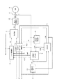
図1は、本発明の一構成例を示すブロック図である。本実施形態の速度センサレス電動機制御装置は、トルク制御部1と、切替部3と、電力変換部4と、電流検出部5と、初期値推定部7と、実磁束推定部9と、演算用タイマ14と、演算部101と、可変ゲイン切替付拾い上げ制御部102とを備える。なお、上述した図5,6に示す従来技術と同様の構成要素については、図5,6と同じ符号を付して説明を省略する。
FIG. 1 is a block diagram showing a configuration example of the present invention. The speed sensorless motor control device of the present embodiment includes a
可変ゲイン切替付拾い上げ制御部102は、電動機6の電流ベクトルiと直流電流指令I、少なくとも1つの(この実施形態では2つの)直流位相角指令θ1,θ2、及び制御ゲインを元に、電流ベクトルiを少なくとも1つの(この実施形態では2つの)位相角の直流電流にする制御ができ、複数の制御を拾い上げ制御切替指令SSにより切り替えて、拾い上げ電圧指令v0を出力する。
The pick-up
演算部101は、実磁束ベクトルφ2r、及び直流位相角指令の少なくとも1つθ1を入力し、拾い上げ制御切替指令SSを出力する。
The
拾い上げ制御切替指令SSは様々な方法で求めることができる。第1の例では、演算用タイマ14が出力する拾い上げ時間t0が所定の値に達したときに、演算部101は、拾い上げ制御切替指令SSをオンにする。
The pick-up control switching command SS can be obtained by various methods. In the first example, when the pick-up time t0 output by the
第2の例では、演算部101は、実磁束ベクトルφ2rの、直流位相角指令θ1に直交する成分の最大値を検知した時点で、拾い上げ制御切替指令SSをオンにする。
In the second example, the
拾い上げ制御切替指令SSは演算用タイマ14に入力され、拾い上げ制御切替指令SSがオフからオンとなるエッジで、拾い上げ時間t0は0クリアされる。
The pick-up control switching command SS is input to the
この実施形態では、演算部101は、拾い上げ時間t0及び実磁束ベクトルφ2rを入力し、電動機6の暫定推定速度ωmaをさらに出力する。
In this embodiment, the
演算用タイマ14が0クリアされた時点から拾い上げ時間t0までの、実磁束ベクトルφ2rの、直流位相角指令θ1に直交する成分の最大値及び最小値を検知した回数をNとし、Nと拾い上げ時間t0との比率から、式 ωma=N/(2・t0) により、暫定推定速度ωma[Hz]を演算することができる。なお、実磁束ベクトルφ2rの、直流位相角指令θ1に直交する成分の最大値の検出は、例えば、当該成分が単調増加から単調減少に転じたことを検出することによって行うことができる。
The number of times that the maximum value and the minimum value of the component perpendicular to the DC phase angle command θ1 of the actual magnetic flux vector φ2r from the time when the
この実施形態の速度センサレス電動機制御装置では、実磁束ベクトルφ2rの状態により、拾い上げ制御切替指令SSが作成され、拾い上げ制御切替指令SSにより拾い上げ制御の直流電流制御状態を切り替えられるようになる。 In the speed sensorless electric motor control device of this embodiment, the pick-up control switching command SS is created according to the state of the actual magnetic flux vector φ2r, and the DC current control state of the pick-up control can be switched by the pick-up control switching command SS.
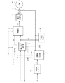
図2は、図1に示す可変ゲイン切替付拾い上げ制御部102の一構成例を示すブロック図である。可変ゲイン切替付拾い上げ制御部102は、第1電流制御部103と、第2電流制御部104と、第2制御ゲイン演算部105と、指令切替部106とを備える。
FIG. 2 is a block diagram showing a configuration example of the pick-up
第1電流制御部103は、直流電流指令I、第1直流位相角指令θ1、及び第1制御ゲインIG1を元に、電動機6に流れる電流ベクトルiを第1直流電流に制御するための第1拾い上げ電圧指令v01を出力する。
The first
第2制御ゲイン演算部105は、第1制御ゲインIG1、及び電動機の暫定推測速度ωmaに基づいて第2制御ゲインIG2を演算する。
The second control
第2制御ゲインIG2は様々な方法で求めることができる。第1の例では、速度しきい値をωmbとして、ωma<ωmbの場合には、IG2=IG1とする。一方、ωma≧ωmbの場合には、IG2=IGG・IG1とする。なお、比例定数IGGは1より大きい定数とする。すなわち、暫定推測速度ωmaが速度しきい値ωmbよりも高速であれば、制御ゲインIG2が制御ゲインIG1よりも大きくなる。 The second control gain IG2 can be obtained by various methods. In the first example, the speed threshold value is ωmb, and IG2 = IG1 when ωma <ωmb. On the other hand, when ωma ≧ ωmb, IG2 = IGG · IG1. The proportionality constant IGG is a constant larger than 1. That is, if the provisional estimated speed ωma is higher than the speed threshold ωmb, the control gain IG2 is larger than the control gain IG1.
第2の例では、比例定数GIGとオフセット定数OIGを用いて、式
![]()
![]()
第2電流制御部104は、直流電流指令I、第2直流位相角指令θ2、及び第2制御ゲインIG2とを元に、電動機6に流れる電流ベクトルiを第2直流電流に制御するための第1拾い上げ電圧指令v02を出力する。
The second
指令切替部106は、拾い上げ制御切替指令SSがオフの場合は、第1拾い上げ電圧指令v01を拾い上げ電圧指令v0として出力する。拾い上げ制御切替指令SSがオンの場合は、第2拾い上げ電圧指令v02を拾い上げ電圧指令v0として出力する。
The
以上の構成とすることにより、電動機6の暫定推定速度ωmaが大きい場合、すなわち電動機6の初期速度が高速の場合に、第2電流制御部104の制御ゲインが大きくなる。切り上げ制御切替指令SSがオフである間、可変ゲイン切替付拾い上げ制御部102の制御ゲインは、小さな第1制御ゲインであるため、その制御遅れが大きくなり、電流ベクトルiに、電動機6の初期速度周波数の脈動が重畳される場合がある。この場合でも、切り上げ制御切替指令SSがオンになると、可変ゲイン切替付拾い上げ制御部102の制御ゲインは、より大きな第2制御ゲインとなるため、その制御遅れが小さくなり、電動機に流れる電流を直流に制御することができる。
With the above configuration, when the provisional estimated speed ωma of the
なお、電動機の初期速度が高速である場合には、上述したように制御遅れが大きくなる傾向にあるため、可変ゲイン切替付拾い上げ制御部102の制御ゲインを大きくしても制御が不安定になる恐れは無い。
When the initial speed of the motor is high, the control delay tends to increase as described above, so that the control becomes unstable even if the control gain of the pick-up
一方、電動機の初期速度が低速の場合は、第2電流制御部104の制御ゲインIG2は大きくならず、可変ゲイン切替付拾い上げ制御部102の制御ゲインも大きくならない。そのため、制御が不安定になる恐れはない。また、可変ゲイン切替付拾い上げ制御部102の制御ゲインが小さくても制御遅れは大きくならず、電動機に流れる電流を直流に制御することができる。
On the other hand, when the initial speed of the motor is low, the control gain IG2 of the second
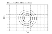
したがって、電動機6の初期速度が低速の場合でも高速の場合でも、電動機6の実磁束ベクトルφ2rの軌跡は、図3のようになり、半径はほとんど変化しない。そのため、式(B)〜式(G)を使った演算では、ベクトルF1,F2の大きさが大きくなり、実磁束推定部9の推定誤差の影響が小さくなる。その結果、電動機6の初期速度及び初期二次磁束をより高精度に推定することができる。また、電動機6の初期速度が低速の場合でも高速の場合でも、制御が不安定になる恐れも無い。
Therefore, regardless of whether the initial speed of the
ところで、式(H)第2項において括弧内の絶対値が小さくなるような残留磁束φxxが存在する場合、式(B)〜式(G)を使った演算は、ベクトルF1,F2の大きさが小さくなるため、実磁束推定部9の推定誤差の影響が大きくなる。その結果、演算精度が悪化し、電動機6の初期速度ωm0及び初期二次磁束φ20の推定に誤差が生じる恐れがある。
By the way, when there is a residual magnetic flux φxx in which the absolute value in the parenthesis is small in the second term of the formula (H), the calculation using the formulas (B) to (G) is the magnitude of the vectors F1 and F2. Therefore, the influence of the estimation error of the actual magnetic flux estimation unit 9 is increased. As a result, the calculation accuracy is deteriorated, and there is a possibility that an error occurs in the estimation of the initial speed ωm0 and the initial secondary magnetic flux φ20 of the
また、モータ使用後に時間をおく等して、残留磁束φxxが十分に小さい場合であっても、推定すべき電動機の初期速度が高い時は、式(H)第2項の括弧内の絶対値が小さくなる。この場合にも、式(B)〜式(G)を使った演算は、ベクトルF1,F2の大きさが小さくなるため、演算精度が悪くなり、初期速度ωm0及び初期二次磁束φ20の推定に誤差が生じる可能性がある。 Also, even if the residual magnetic flux φxx is sufficiently small, such as after a period of time after use of the motor, if the initial speed of the electric motor to be estimated is high, the absolute value in parentheses in the second term of equation (H) Becomes smaller. In this case as well, the calculations using the equations (B) to (G) are less accurate because the magnitudes of the vectors F1 and F2 are small, and the initial speed ωm0 and the initial secondary magnetic flux φ20 are estimated. An error may occur.
このように、特に残留磁束がある場合や、電動機6の初期速度が高速の場合は、初期速度ωm0及び初期二次磁束φ20の推定値に誤差が生じ、その結果、トルク制御部1の初期入力値に誤差があるために、電動機6のトルク制御を高精度に行うことができない恐れがある。ここで、直流電力指令Iを大きくすれば、式(H)第2項の括弧内の絶対値を大きくすることはできるが、その場合には、電動機6の挙動に影響を及ぼす恐れがある。
Thus, particularly when there is residual magnetic flux or when the initial speed of the
ここで、電動機6の初期速度ωm0及び初期二次磁束φ20の推定値の誤差を小さくする観点から、第2直流位相角指令θ2は、第1直流位相角指令θ1とは異なる値にすることが好ましい。当該誤差をより確実に小さくする観点から、より好ましくは、第2直流位相角指令θ2を、第1直流位相角指令θ1から180度反転した値にする。
Here, from the viewpoint of reducing errors in the estimated values of the initial speed ωm0 and the initial secondary magnetic flux φ20 of the
この構成により、以下のような拾い上げ制御が実現できる。なお、説明を簡略化するために、第1直流位相角指令θ1は0°とし、第2直流位相角指令θ2は180°とする。すなわち、第1電流制御部103は電流ベクトルiを第1直流電流(I,0)に制御し、第2電流制御部104は電流ベクトルiを第2直流電流(−I,0)に制御する。
With this configuration, the following pickup control can be realized. In order to simplify the description, the first DC phase angle command θ1 is 0 °, and the second DC phase angle command θ2 is 180 °. That is, the first
可変ゲイン切り替え付拾い上げ制御部102は、拾い上げ制御切替指令SSがオフの状態から拾い上げ制御を開始する。この時点の時刻を0とする。第1拾い上げ電圧指令v01が拾い上げ電圧指令v0として出力されるので、電流ベクトルiは第1直流電流(I,0)に制御される。拾い上げ制御を開始し、拾い上げ制御切替指令SSがオンになるまでの、電動機6の実磁束ベクトルφ2rの軌跡は、図4に示す円弧C1で示される。
The pick-up
演算部101は、実磁束ベクトルφ2rの第1直流位相角指令θ1に直交する成分の最大値を検知した時点で、拾い上げ制御切替指令SSをオンにする。今回、θ1を0°としたので、実磁束ベクトルφ2rの虚軸(B軸)成分が最大である時刻t1、すなわちφ2rの軌跡が図4のB軸の正側と交差した時点で、拾い上げ制御切替指令SSはオンになる。
以降、第2拾い上げ電圧指令v02が拾い上げ電圧指令v0として出力されるので、電流ベクトルiは第2直流電流(−I,0)に制御される。拾い上げ制御切替指令SSがオンになった後の、実磁束ベクトルφ2rの軌跡は、図4に示す円弧C2で示される。この円弧C2の軌跡においては、φ(t1)が式(H)に示す残留磁束φxxとなるため、円弧C1の半径をrとすると、円弧C2の半径は、r+φ(t1)となる。従って、上述したように拾い上げ電圧指令SSを切り替えることで、直流電流指令Iを大きくすることなしに、実磁束ベクトルφ2rが描く円弧の半径、すなわち式(H)第2項の括弧内の絶対値を大きくして、電動機6の初期速度ωm0及び初期二次磁束φ20の推定値の誤差を小さくすることができる。
Thereafter, since the second pick-up voltage command v02 is output as the pick-up voltage command v0, the current vector i is controlled to the second DC current (−I, 0). The locus of the actual magnetic flux vector φ2r after the pickup control switching command SS is turned on is indicated by an arc C2 shown in FIG. In the locus of the arc C2, φ (t 1 ) is the residual magnetic flux φxx shown in the equation (H). Therefore, if the radius of the arc C1 is r, the radius of the arc C2 is r + φ (t 1 ). Therefore, by switching the pick-up voltage command SS as described above, without increasing the DC current command I, the radius of the arc drawn by the actual magnetic flux vector φ2r, that is, the absolute value in parentheses in the second term of the equation (H) To increase the error of the estimated values of the initial speed ωm0 and the initial secondary magnetic flux φ20 of the
本発明により、制御不安定を招くことなく電流iを直流に制御できるようになり、実磁束ベクトルの円軌跡の半径の急激な減少を防止できる。その結果、電動機の初期速度及び初期二次磁束を高精度に推定することができ、電動機トルクを高精度に制御することができる。 According to the present invention, the current i can be controlled to a direct current without causing control instability, and a sudden decrease in the radius of the circular locus of the actual magnetic flux vector can be prevented. As a result, the initial speed and initial secondary magnetic flux of the motor can be estimated with high accuracy, and the motor torque can be controlled with high accuracy.
また、直流位相角指令の与え方を工夫することにより、直流電流指令Iを大きくすることなく、高精度な電動機の初期速度及び初期二次磁束の推定を期待できる。 Further, by devising how to give the DC phase angle command, it is possible to estimate the initial speed and the initial secondary magnetic flux of the motor with high accuracy without increasing the DC current command I.
1 トルク制御部
2 拾い上げ制御部
3 切替部
4 電力変換部
5 電流検出部
6 電動機
7 初期値推定部
9 実磁束推定部
10 実磁束メモリ
11 実磁束抽出部
12 初期速度推定部
13 初期磁束推定部
14 演算用タイマ
101 演算部
102 可変ゲイン切替付拾い上げ制御部
103 第1電流制御部
104 第2電流制御部
105 第2制御ゲイン演算部
106 指令切替部
DESCRIPTION OF
Claims (5)
直流電流指令及び複数の直流位相角指令を元に、前記電流ベクトルを前記複数の直流位相角指令各々の直流電流に制御するための電圧指令を出力し、拾い上げ制御切替指令により前記複数の電圧指令から1つを選択し拾い上げ電圧指令として出力する可変ゲイン切替付拾い上げ制御部と、
前記電流ベクトル及び前記拾い上げ電圧指令を入力し、実磁束ベクトルを出力する実磁束推定部と、
前記電流ベクトル、前記実磁束ベクトル、及び拾い上げ時間を入力し、前記電動機の初期速度及び初期二次磁束を出力する初期値推定部と、
前記実磁束ベクトル及び前記直流位相角指令の少なくとも1つを入力し、前記拾い上げ制御切替指令を出力する演算部と、
を備えることを特徴とする速度センサレス電動機制御装置。 A current detector for detecting a current vector flowing in the electric motor;
The direct current finger Ryo及 beauty based on a plurality of direct current phase angle command, the current vector output a voltage command for controlling said plurality of direct current phase angle command of each of the DC current, the plurality of the control switching command picked A pick-up control unit with variable gain switching for selecting one of the voltage commands and outputting it as a pick-up voltage command;
An actual magnetic flux estimation unit that inputs the current vector and the pick-up voltage command and outputs an actual magnetic flux vector;
An initial value estimation unit that inputs the current vector, the actual magnetic flux vector, and the pick-up time, and outputs an initial speed and an initial secondary magnetic flux of the motor;
An arithmetic unit that inputs at least one of the actual magnetic flux vector and the DC phase angle command, and outputs the pickup control switching command;
A speed sensorless motor control device comprising:
前記直流電流指令、前記直流位相角指令、及び第1制御ゲインを元に、前記電流ベクトルを第1直流電流に制御するための第1拾い上げ電圧指令を出力する第1電流制御部と、
前記直流電流指令、前記直流位相角指令、及び第2制御ゲインを元に、前記電流ベクトルを第2直流電流に制御するための第2拾い上げ電圧指令を出力する第2電流制御部と、
前記第1拾い上げ電圧指令及び前記第2拾い上げ電圧指令を、前記拾い上げ制御切替指令により切り替えて前記拾い上げ電圧指令とする指令切替部と、
を備えることを特徴とする、請求項1に記載の速度センサレス電動機制御装置。 The pick-up control unit with variable gain switching is
A first current control unit that outputs a first pick-up voltage command for controlling the current vector to a first DC current based on the DC current command, the DC phase angle command, and a first control gain;
A second current control unit that outputs a second pick-up voltage command for controlling the current vector to a second DC current based on the DC current command, the DC phase angle command, and a second control gain;
A command switching unit that switches the first pick-up voltage command and the second pick-up voltage command by the pick-up control switching command to be the pick-up voltage command;
The speed sensorless motor control device according to claim 1, comprising:
Priority Applications (1)
| Application Number | Priority Date | Filing Date | Title |
|---|---|---|---|
| JP2013155825A JP6144989B2 (en) | 2013-07-26 | 2013-07-26 | Speed sensorless motor controller |
Applications Claiming Priority (1)
| Application Number | Priority Date | Filing Date | Title |
|---|---|---|---|
| JP2013155825A JP6144989B2 (en) | 2013-07-26 | 2013-07-26 | Speed sensorless motor controller |
Publications (3)
| Publication Number | Publication Date |
|---|---|
| JP2015027191A JP2015027191A (en) | 2015-02-05 |
| JP2015027191A5 JP2015027191A5 (en) | 2016-07-21 |
| JP6144989B2 true JP6144989B2 (en) | 2017-06-07 |
Family
ID=52491441
Family Applications (1)
| Application Number | Title | Priority Date | Filing Date |
|---|---|---|---|
| JP2013155825A Active JP6144989B2 (en) | 2013-07-26 | 2013-07-26 | Speed sensorless motor controller |
Country Status (1)
| Country | Link |
|---|---|
| JP (1) | JP6144989B2 (en) |
Families Citing this family (1)
| Publication number | Priority date | Publication date | Assignee | Title |
|---|---|---|---|---|
| CN109150055B (en) * | 2018-09-14 | 2020-04-10 | 清华大学 | Electromagnetic torque feedback control system and method in I/F control of permanent magnet synchronous motor |
Family Cites Families (3)
| Publication number | Priority date | Publication date | Assignee | Title |
|---|---|---|---|---|
| JP4139934B2 (en) * | 1999-09-21 | 2008-08-27 | 株式会社安川電機 | AC motor control method and control apparatus |
| ITPR20020074A1 (en) * | 2002-12-03 | 2004-06-04 | Zapi S P A | PROCEDURE FOR MEASURING THE SPEED OF AN INDUCTION MOTOR FROM THE STATE OF FREQUENCY NOTHING. |
| JP4641748B2 (en) * | 2004-06-25 | 2011-03-02 | 東洋電機製造株式会社 | Speed sensorless motor controller |
-
2013
- 2013-07-26 JP JP2013155825A patent/JP6144989B2/en active Active
Also Published As
| Publication number | Publication date |
|---|---|
| JP2015027191A (en) | 2015-02-05 |
Similar Documents
| Publication | Publication Date | Title |
|---|---|---|
| JP5176420B2 (en) | Sensorless control device for brushless motor | |
| US7501787B2 (en) | Method for controlling AC motor | |
| JP5573714B2 (en) | Rotating machine control device | |
| JP2004282807A (en) | Sensorless vector control method of ac motor, and control device thereof | |
| CN109309466A (en) | Control device of electric motor | |
| JP4670405B2 (en) | Vector control method for synchronous motor | |
| JP5733404B2 (en) | PM motor position sensorless control device | |
| JP2010041868A (en) | Rotor rotation monitor for synchronous motor, and control system | |
| JP6144989B2 (en) | Speed sensorless motor controller | |
| JP5564828B2 (en) | AC motor control device | |
| JP4657892B2 (en) | Rotor angle estimation device and rotor angle estimation method for DC brushless motor | |
| JP6953302B2 (en) | Speed sensorless motor controller | |
| JP2010045884A (en) | Motor driving device and current detection method | |
| JP6394885B2 (en) | Electric power steering device | |
| JP4680754B2 (en) | DC brushless motor rotor angle estimation method and DC brushless motor control device | |
| JP6082258B2 (en) | Speed sensorless motor controller | |
| JP7446968B2 (en) | Control device | |
| JP6308894B2 (en) | Control device for three-phase AC rotating machine | |
| JP6451361B2 (en) | Control device for three-phase rotating electric machine | |
| JP6032047B2 (en) | Motor control device | |
| JP2008193796A (en) | Controller of permanent magnet motor, control method of permanent magnet motor, and module | |
| JP4592138B2 (en) | Speed sensorless motor controller | |
| JP6572077B2 (en) | Speed sensorless motor controller | |
| CN109309467A (en) | Control device of electric motor | |
| US11799407B2 (en) | Drive system and method for controlling a synchronous motor having several phases |
Legal Events
| Date | Code | Title | Description |
|---|---|---|---|
| A521 | Written amendment |
Free format text: JAPANESE INTERMEDIATE CODE: A523 Effective date: 20160525 |
|
| A621 | Written request for application examination |
Free format text: JAPANESE INTERMEDIATE CODE: A621 Effective date: 20160525 |
|
| A521 | Written amendment |
Free format text: JAPANESE INTERMEDIATE CODE: A523 Effective date: 20160527 |
|
| A977 | Report on retrieval |
Free format text: JAPANESE INTERMEDIATE CODE: A971007 Effective date: 20170224 |
|
| A131 | Notification of reasons for refusal |
Free format text: JAPANESE INTERMEDIATE CODE: A131 Effective date: 20170228 |
|
| A521 | Written amendment |
Free format text: JAPANESE INTERMEDIATE CODE: A523 Effective date: 20170424 |
|
| TRDD | Decision of grant or rejection written | ||
| A01 | Written decision to grant a patent or to grant a registration (utility model) |
Free format text: JAPANESE INTERMEDIATE CODE: A01 Effective date: 20170509 |
|
| A61 | First payment of annual fees (during grant procedure) |
Free format text: JAPANESE INTERMEDIATE CODE: A61 Effective date: 20170512 |
|
| R150 | Certificate of patent or registration of utility model |
Ref document number: 6144989 Country of ref document: JP Free format text: JAPANESE INTERMEDIATE CODE: R150 |