JP6139409B2 - Hinged shield assembly and associated method - Google Patents
Hinged shield assembly and associated method Download PDFInfo
- Publication number
- JP6139409B2 JP6139409B2 JP2013541017A JP2013541017A JP6139409B2 JP 6139409 B2 JP6139409 B2 JP 6139409B2 JP 2013541017 A JP2013541017 A JP 2013541017A JP 2013541017 A JP2013541017 A JP 2013541017A JP 6139409 B2 JP6139409 B2 JP 6139409B2
- Authority
- JP
- Japan
- Prior art keywords
- shield
- socket
- ball
- side wall
- needle
- Prior art date
- Legal status (The legal status is an assumption and is not a legal conclusion. Google has not performed a legal analysis and makes no representation as to the accuracy of the status listed.)
- Expired - Fee Related
Links
Images


Classifications
-
- A—HUMAN NECESSITIES
- A61—MEDICAL OR VETERINARY SCIENCE; HYGIENE
- A61M—DEVICES FOR INTRODUCING MEDIA INTO, OR ONTO, THE BODY; DEVICES FOR TRANSDUCING BODY MEDIA OR FOR TAKING MEDIA FROM THE BODY; DEVICES FOR PRODUCING OR ENDING SLEEP OR STUPOR
- A61M5/00—Devices for bringing media into the body in a subcutaneous, intra-vascular or intramuscular way; Accessories therefor, e.g. filling or cleaning devices, arm-rests
- A61M5/178—Syringes
- A61M5/31—Details
- A61M5/32—Needles; Details of needles pertaining to their connection with syringe or hub; Accessories for bringing the needle into, or holding the needle on, the body; Devices for protection of needles
- A61M5/3205—Apparatus for removing or disposing of used needles or syringes, e.g. containers; Means for protection against accidental injuries from used needles
- A61M5/321—Means for protection against accidental injuries by used needles
- A61M5/3216—Caps placed transversally onto the needle, e.g. pivotally attached to the needle base
-
- A—HUMAN NECESSITIES
- A61—MEDICAL OR VETERINARY SCIENCE; HYGIENE
- A61M—DEVICES FOR INTRODUCING MEDIA INTO, OR ONTO, THE BODY; DEVICES FOR TRANSDUCING BODY MEDIA OR FOR TAKING MEDIA FROM THE BODY; DEVICES FOR PRODUCING OR ENDING SLEEP OR STUPOR
- A61M5/00—Devices for bringing media into the body in a subcutaneous, intra-vascular or intramuscular way; Accessories therefor, e.g. filling or cleaning devices, arm-rests
- A61M5/178—Syringes
- A61M5/31—Details
- A61M5/32—Needles; Details of needles pertaining to their connection with syringe or hub; Accessories for bringing the needle into, or holding the needle on, the body; Devices for protection of needles
- A61M5/3202—Devices for protection of the needle before use, e.g. caps
-
- A—HUMAN NECESSITIES
- A61—MEDICAL OR VETERINARY SCIENCE; HYGIENE
- A61M—DEVICES FOR INTRODUCING MEDIA INTO, OR ONTO, THE BODY; DEVICES FOR TRANSDUCING BODY MEDIA OR FOR TAKING MEDIA FROM THE BODY; DEVICES FOR PRODUCING OR ENDING SLEEP OR STUPOR
- A61M5/00—Devices for bringing media into the body in a subcutaneous, intra-vascular or intramuscular way; Accessories therefor, e.g. filling or cleaning devices, arm-rests
- A61M5/178—Syringes
- A61M5/31—Details
- A61M5/32—Needles; Details of needles pertaining to their connection with syringe or hub; Accessories for bringing the needle into, or holding the needle on, the body; Devices for protection of needles
- A61M5/3205—Apparatus for removing or disposing of used needles or syringes, e.g. containers; Means for protection against accidental injuries from used needles
- A61M5/321—Means for protection against accidental injuries by used needles
- A61M5/3216—Caps placed transversally onto the needle, e.g. pivotally attached to the needle base
- A61M5/3219—Semi-automatic repositioning of the cap, i.e. in which the repositioning of the cap to the needle covering position requires a deliberate action by the user to trigger the repositioning of the cap, e.g. manual release of spring-biased cap repositioning means
-
- A—HUMAN NECESSITIES
- A61—MEDICAL OR VETERINARY SCIENCE; HYGIENE
- A61M—DEVICES FOR INTRODUCING MEDIA INTO, OR ONTO, THE BODY; DEVICES FOR TRANSDUCING BODY MEDIA OR FOR TAKING MEDIA FROM THE BODY; DEVICES FOR PRODUCING OR ENDING SLEEP OR STUPOR
- A61M5/00—Devices for bringing media into the body in a subcutaneous, intra-vascular or intramuscular way; Accessories therefor, e.g. filling or cleaning devices, arm-rests
- A61M5/178—Syringes
- A61M5/31—Details
- A61M5/32—Needles; Details of needles pertaining to their connection with syringe or hub; Accessories for bringing the needle into, or holding the needle on, the body; Devices for protection of needles
- A61M5/3205—Apparatus for removing or disposing of used needles or syringes, e.g. containers; Means for protection against accidental injuries from used needles
- A61M2005/3206—Needle or needle hub disconnecting devices forming part of or being attached to the hub or syringe body
Description
本明細書において、包括的には、針装置用のシールドが記載され、より詳細には、皮下注射針とともに使用するヒンジ式シールド機構が記載される。 In this specification, a shield for a needle device is generally described, and more particularly a hinged shield mechanism for use with a hypodermic needle.
リキャップは、針による注射器への液体の吸い上げと注射液投与との間によく行われる手順である。リキャップ手順は場合によっては、使用者が針とキャップの開口との位置合わせを誤ることがあるため、針刺し(needlesticks)を引き起こす可能性がある。注射後及び針の廃棄前にも負傷が生じる可能性がある。針刺しは、痛みを伴う場合もあるし、全ての針刺しを報告せねばならないため、多大な面倒も生じさせる場合もある。また、針刺しに関与した針を廃棄せねばならないため、注射器内に入っている薬剤が無駄に廃棄される。さらに、これらの「純粋な(clean)」タイプの針刺しに関わった液は、負傷及び有害反応を生じさせる可能性がある。 Recapping is a common procedure between the pumping of liquid into a syringe by a needle and the administration of an injection solution. In some cases, the recap procedure can cause needlesticks because the user may misalign the needle with the cap opening. Injuries can occur after injection and before needle disposal. Needle sticks can be painful and can be very cumbersome because all needle sticks must be reported. In addition, since the needle involved in the needle stick must be discarded, the medicine contained in the syringe is wasted. In addition, fluids associated with these “clean” types of needle sticks can cause injury and adverse reactions.
本ヒンジ式シールドアセンブリ及び関連する方法の種々の実施の形態は、幾つかの特徴を有しており、それらの特徴のうちの1つだけがその望ましい特質に関与するものではない。ここで、後に続く特許請求の範囲によって明示されるような本実施の形態の範囲に限定することなく、それらのより顕著な特徴を概説する。この説明を考慮した後、特に「発明を実施するための形態」と見出しのついた項を読んだ後では、当業者は、本実施の形態の特徴が、シールドを手で把持する必要も手で扱う必要もなく針ハブに対して任意の所望の向きでシールドを保持する性能を含む利点をどのようにして提供するのかを理解するであろう。 The various embodiments of the present hinged shield assembly and associated method have several features, and only one of those features is not responsible for its desirable attributes. Here, the more prominent features will be outlined without being limited to the scope of the present embodiment as specified by the following claims. After considering this description, and especially after reading the section headed “Mode for Carrying Out the Invention”, those skilled in the art will appreciate that the features of this embodiment also require that the shield be gripped by hand. It will be understood how to provide benefits including the ability to hold the shield in any desired orientation relative to the needle hub without having to deal with.
本ヒンジ式シールドアセンブリの一態様は、現代の多くのヒンジ式シールドアセンブリが「一体」ヒンジを使用しているという認識を含んでいる。一体ヒンジは、第1のヒンジ部品及び第2のヒンジ部品を一体構造で接合する、射出成形プラスチックの比較的薄い部分である。針を覆うヒンジ式シールドアセンブリに関して、一体ヒンジは、開いている位置に留まらずに針保護位置へ付勢する傾向さえもあるという、少なくとも1つの欠点を有する。したがって、針及びシールドアセンブリを使用して注射又は採血を行う場合、操作者は自分の指(複数の指)を使ってシールドを針から離しておくように手で保持する必要があるであろう。或る特定の例では、保持機構を用いてキャップを一時的固定位置に保持又はキープする。このように、一体ヒンジは、上記の問題を解消する手段が設けられない限り、この手順をより煩わしくする。 One aspect of the present hinged shield assembly includes the recognition that many modern hinged shield assemblies use “integral” hinges. The integral hinge is a relatively thin piece of injection molded plastic that joins the first and second hinge parts together in a unitary structure. With respect to the hinged shield assembly that covers the needle, the integral hinge has at least one drawback: it does not stay in the open position but also tends to bias to the needle protected position. Thus, when an injection or blood collection is performed using a needle and shield assembly, the operator will need to hold the shield by hand using his or her fingers (multiple fingers) away from the needle. . In one particular example, a holding mechanism is used to hold or keep the cap in a temporarily fixed position. Thus, the integral hinge makes this procedure more cumbersome unless means are provided to eliminate the above problems.
本ヒンジ式シールドアセンブリの1つの実施形態は、第1のヒンジ部分を備える針ハブを含む。該針ハブから針が延びる。該シールドアセンブリは、第2のヒンジ部分を備えるシールドであって、前記第2のヒンジ部分は該シールドを前記ハブに枢動可能に固定するように前記第1のヒンジ部分に係合する、シールドを更に含む。該シールドは、該シールドアセンブリが保護位置にあるときに前記針を部分的に囲むように構成されている複数の側壁を更に含む。前記第1のヒンジ部分及び前記第2のヒンジ部分のうちの一方は、第1のボール及び第2のボールを画定し、前記1のヒンジ部分及び前記第2のヒンジ部分のうちの他方は、第1のソケット及び第2のソケットを画定する。第1のソケット及び第2のソケットは前記第1のボール及び前記第2のボールを枢動可能な係合で受け入れる。 One embodiment of the present hinged shield assembly includes a needle hub with a first hinge portion. A needle extends from the needle hub. The shield assembly is a shield comprising a second hinge portion, the second hinge portion engaging the first hinge portion to pivotally secure the shield to the hub. Is further included. The shield further includes a plurality of sidewalls configured to partially surround the needle when the shield assembly is in a protected position. One of the first hinge portion and the second hinge portion defines a first ball and a second ball, and the other of the first hinge portion and the second hinge portion is A first socket and a second socket are defined. A first socket and a second socket receive the first ball and the second ball in a pivotable engagement.
本方法の1つの実施形態は、針刺しを防止するために針をシールドするように構成されているヒンジ式シールドアセンブリを製造する方法を含む。該アセンブリは、針ハブとシールドとを含む。該シールドは、前記シールドアセンブリが保護位置にあるときに前記針を部分的に囲むように構成されている複数の側壁を更に含む。該方法は、第1のヒンジ部分を有する前記針ハブを形成することと、前記針を前記針ハブに固定することとを含む。該方法は、第2のヒンジ部分を有する前記シールドを形成することを更に含む。該方法は、前記シールドを前記ハブに枢動可能に固定するように前記第1のヒンジ部分及び前記第2のヒンジ部分を互いに係合させることを更に含む。前記第1のヒンジ部分及び前記第2のヒンジ部分のうちの一方は、第1のボール及び第2のボールを画定し、前記第1のヒンジ部分及び前記第2のヒンジ部分のうちの他方は、第1のソケット及び第2のソケットを画定する。前記第1のソケット及び前記第2のソケットは前記第1のボール及び前記第2のボールを枢動可能な係合で受け入れる。 One embodiment of the method includes a method of manufacturing a hinged shield assembly that is configured to shield the needle to prevent needle stick. The assembly includes a needle hub and a shield. The shield further includes a plurality of sidewalls configured to partially surround the needle when the shield assembly is in a protected position. The method includes forming the needle hub having a first hinge portion and securing the needle to the needle hub. The method further includes forming the shield having a second hinge portion. The method further includes engaging the first hinge portion and the second hinge portion together to pivotally secure the shield to the hub. One of the first hinge portion and the second hinge portion defines a first ball and a second ball, and the other of the first hinge portion and the second hinge portion is , Defining a first socket and a second socket. The first socket and the second socket receive the first ball and the second ball in a pivotable engagement.
本方法の別の実施形態は、針刺しを防止するために針をシールドするヒンジ式シールドアセンブリを使用する方法を含む。該アセンブリは、針ハブとシールドとを含む。該シールドは、複数の側壁を更に含む。該方法は、前記シールドを前記ハブに枢動可能に固定するヒンジを中心に前記ハブに対して前記シールドを枢動させることを含む。該方法は、前記側壁が保護位置において前記針を部分的に囲むまで前記ハブに対して前記シールドを枢動させ続けることを更に含む。該方法は、前記保護位置において、前記ハブに対して又は前記針に対して前記シールドをロックすることを更に含む。前記ヒンジを中心に前記ハブに対して前記シールドを枢動させることは、第1のソケット内で第1のボールを枢動させることと、第2のソケット内で第2のボールを枢動させることとを含む。 Another embodiment of the method includes a method of using a hinged shield assembly that shields the needle to prevent needle stick. The assembly includes a needle hub and a shield. The shield further includes a plurality of sidewalls. The method includes pivoting the shield relative to the hub about a hinge that pivotally secures the shield to the hub. The method further includes continuing to pivot the shield relative to the hub until the side wall partially surrounds the needle in a protected position. The method further includes locking the shield to the hub or to the needle in the protected position. Pivoting the shield with respect to the hub about the hinge causes the first ball to pivot within the first socket and the second ball to pivot within the second socket. Including.
次に、本ヒンジ式シールドアセンブリの種々の実施形態を、有利な特徴を強調することに重点を置いて詳細に説明する。これらの実施形態は、添付の図面に示されている新規の自明でないヒンジ式シールドアセンブリを示し、これらは単に例示のためのものである。これらの図面は以下の図を含み、同様の符号は同様の部材を示す。 Various embodiments of the present hinged shield assembly will now be described in detail with an emphasis on highlighting advantageous features. These embodiments show the novel non-obvious hinged shield assembly shown in the accompanying drawings, which are for illustration only. These drawings include the following figures, wherein like numerals indicate like members.
以下の詳細な説明は、図を参照しながら、装置、デバイス及び方法を含む本実施形態を説明する。図面中、参照符号が本実施形態の要素に付されている。これらの参照符号は、対応する図示の特徴の説明に関して以下で繰り返される。 The following detailed description describes the present embodiments including apparatus, devices and methods with reference to the drawings. In the drawings, reference numerals are assigned to elements of this embodiment. These reference numerals are repeated below with respect to the description of the corresponding illustrated features.
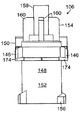
図1〜図18は、ヒンジ式シールドアセンブリ及びそれらの構成部材の種々の変形形態を示す。ヒンジ式シールドアセンブリ100が、注射器102(図1、部分的に図示)と協働し、針ハブ106から延びる針104(図1及び図4)を選択的にシールドするシールド108を含み、針ハブ106は注射器102の遠位端に係合する。図1及び図3を参照すると、シールドアセンブリ100は、ハブ106と、ハブ106を中心に枢動可能なシールド108とを含む。以下で更に詳細に記載されるように、シールド108は、包装(packaged)位置(図4)から使用準備完了位置(図3)へ、使用準備完了位置から開位置(図2)へ、また、開位置から固定位置(図1)へ操作されるように構成されている。
1-18 illustrate various variations of the hinged shield assemblies and their components. The hinged
図5〜図7を参照すると、シールド108は、針104を囲むように構成されている第1の側壁110、第2の側壁112及び第3の側壁114を3つの面に含む。第3の側壁114は、中央壁又は後壁と呼ぶこともでき、第1の側壁110と第2の側壁112との間に位置決めされている。図6を参照すると、第1の側壁110及び第2の側壁112は、シールド108の基端116において互いに対して概ね平行になっており、その後、互いに向かって次第に窄まり、そしてその後、互いに対して平行を維持している。図5を参照すると、第3の側壁114は、斜めのベース部分118から凹状部分120まで傾斜している。凹状部分120の外面は、シールド108を把持しやすくする横方向リッジ122を含む。3つの全ての側壁110、112、114は、約90度で接合されている。しかしながら、シールド108のベース116近くでは、第1の側壁110及び第2の側壁112は、第3の側壁114から僅かに離間しており、第1のスリット及び第2のスリット124(図6)を形成している。以下で更に記載されるように、スリット124により、第1の側壁110及び第2の側壁112が互いから離れる方向に撓んで、製造時にシールド108をハブ106に取り付けやすくすることが可能になる。
5-7, the
図5を参照すると、側壁110、112、114は、シールド108の長さの約半分にわたって延び、肩部分126に隣接しており、この肩部分126は3つの全ての側壁110、112、114の縁から横方向内側に延びている。シュラウド128が、側壁110、112、114から離れる方向に肩部分126から延びている。シュラウド128は略U字状の断面を有する。シュラウド128は、シールド108の基端116に対向する端において閉じている。シールド108は、以下で詳細に説明されるように、シールド108がハブ106に対して枢動する際の針104の通過に適応するように片側に沿って開いている。
Referring to FIG. 5, the
図4及び図6を参照すると、シールド108は、第3の側壁114から内側に延びる第1のフック130と、シュラウド128から内側に延びる第2のフック130とを更に備える。図示の実施形態では、フック130はシールド108と一体形成されている。フック130は、シールド108が針104に向かって枢動したときに針104を捕捉してシールド108を針保護位置に固定するように構成されている。シールド108が針104に向かって枢動する際、各フック130の傾斜した端面又は丸みのある端面132が針104に接触し、フック130を側方に撓ませてフック130を針104の周囲にスナップするとともに針104を捕捉することを可能にする。他の例では、1つのフック又は3つ以上のフックを組み込むことができる。更に他の例では、フックの位置は、フックが針及び/又は針ハブの異なるセクションを固定するように変更することができる。
With reference to FIGS. 4 and 6, the
図5〜図7を参照すると、シールド108の基端116は、第1及び第2のボールジョイント又はボール134と、第1及び第2のタブ136とを備える。ボール134は、第1の側壁110及び第2の側壁112の第1のコーナー138に隣接する内面から、内側に延びている。タブ136は、第1の側壁110及び第2の側壁112の第2のコーナー140に隣接する内面から、内側に延びている。図2を参照すると、ボール134は、シールド108及びハブ106の互いに対する枢動のためにボールソケットヒンジ144を形成するよう、ハブ106のソケット142内に収納されるように構成されている。したがって、ヒンジ144は、可動ヒンジを形成するようにともに連結される2つ以上の別個に形成された構成部材、すなわち多部品を含むことが理解される。図3を参照すると、タブ136は、シールド108を針保護位置に固定するよう、ハブ106のレッジ146の下に納まるように構成されている。これらの態様は以下で詳細に記載する。
With reference to FIGS. 5-7, the
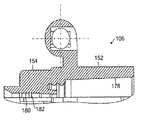
図12〜図18は、ハブ106を詳細に示す。図12及び図13を参照すると、ハブ106は、円筒形部分148と横方向ベース部分150とを備える。ベース部分150は、円筒形部分148を実質的に分断しており、近位の円筒形部分152及び遠位の円筒形部分154(図13)を画定している。近位の円筒形部分152は、滑らかな中空の円筒として形付けられており、その近位端において雄ねじ156を含む。雄ねじ156は、シールド108を注射器に固定するよう、注射器の遠位端における雌ねじ(図示せず)に係合するように構成されている。遠位の円筒形部分154は、中空のシリンダー158であって、外側に延びているとともにこのシリンダー158の軸に対して平行なフィン160を有する、中空のシリンダー158を備える。均一に間隔をあけた4つのフィンが図示されているが、任意の数のフィンを設けることができる。中空のシリンダー158は、図4に示されているように、このシリンダー158の内部に配置される針104との接着係合(glued engagement)で、針104の鈍い近位端を受け入れるように構成されている。代替的な実施形態では、この係合は圧入係合とすることができる。
12-18 show the
図3、図12及び図13を参照すると、横方向ベース部分150は、本実施形態では実質的に円筒形の部分164であるヒンジ部品164に一端が隣接している実質的に平面の部分162を含む。図14及び図15に示されているように、円筒形の部分164は、ボールソケットヒンジ144の第1及び第2のソケット部分166を含む。図15を参照すると、各ソケット部分166は、傾斜リム170を有する開口168を含む。開口168からソケット部分166の直径が変化し、比較的狭い開口168から、開口168の内方に急激に拡径し、次に、より狭い直径へと徐々に窄まる。この可変直径の開口は、ボールソケットヒンジのボールを受け入れるように構成されている。
With reference to FIGS. 3, 12 and 13, the
ソケット部分166における直径の変化により、図2に示されているような、ボール134を受け入れるソケット142が形成される。各ボール134は、各ソケット142の最大径に概ね等しいが開口168の直径(図15)よりも大きい直径を有する。したがって、ボール134は、開口168が各ボール134の直径よりも小さい直径を有しているため、ソケット142内に着座し、ソケット142からの離脱に抗する。ボール134とソケット142との相対的なサイズは、ソケット142内でのボール134の回転に対する所望の量の抵抗及び干渉度をもたらすように適合させることができる。また、以下で記載されるように、ボール134の形状は、動きの所望の滑らかさをもたらすように又は滑らかさを欠くように、適合させることもできる。
The change in diameter at the
図3、図12及び図13を参照すると、針ハブ106は、可逆性シールドロック172の第1の部分146を更に備える。ソケット142の対向するコーナーにおいて、ハブ106は、横方向ベース150の近位側にノッチ174を形成するレッジ146を備える。ノッチ174は、シールド108のタブ136に相補的であるサイズ及び形状になっている。タブ136は、シールド108が針保護位置に向かって枢動するとノッチ174にスナップインしてシールド108をその位置に保持する。図3を参照すると、レッジ146の、ノッチ174と反対側の表面176は、シールド108が保護位置に向かって枢動する際にタブ136が傾斜面176上を摺動して外方に歪むように傾斜している。タブ136は、レッジ146の周囲で摺動する際、ノッチ174にスナップインして、シールド108が保護位置から離れる方向に枢動することを阻止する。しかしながら、タブ136、ノッチ174及びレッジ146がもたらすロック動作は可逆性である。操作者は、第1の側壁110及び第2の側壁112を互いから離れる方向に撓ませるように、指圧を加えることができる。側壁を十分に撓ませることによって、タブ136がレッジ146から外れる(clear)ことができ、それによって、シールド108が保護位置から離れる方向に枢動することができる。
With reference to FIGS. 3, 12, and 13, the
図16〜図18は、ハブ106の構造を更に示す。図18を参照すると、近位の円筒形部分152は、注射器102(図1)の雄テーパー状先端を嵌合して受け入れるように構成されている雌テーパー178をその内側に含む。遠位の円筒形部分154もまた、針104(図4)の近位の鈍端を受け入れるように構成されている雌ボア180をその内側に含む。遠位の円筒形部分154は、針104の環状のリッジ184(図4)を受け入れるように構成されている、長手方向に間隔をあけた複数の環状の窪み182(図18)も含む。代替的な実施形態では、円筒形部分154は、別個に設けられた組合せ型の針ハブ及び針に突出する雄テーパーを有する。この代替的な実施形態により、医療従事者が任意の数の針サイズをヒンジ式キャップ機構とともに使用することが可能になる。
16 to 18 further illustrate the structure of the
図1〜図4は、組み付けられた状態のヒンジ式シールドアセンブリ100を示す。アセンブリ100を製造する際、シールド108の基端116のエリアにおいて第1の側壁110及び第2の側壁112(図2及び図3)を互いから離れる方向に撓ませることによって、シールド108をハブ106に組み付ける。第1の側壁110と第3の側壁114との間及び第2の側壁112と第3の側壁114との間のスリット124(図5及び図6)により、撓ませやすくなっている。次に、シールド108及びハブ106を、ボール134がソケット142内の開口168(図15)のすぐ外側にあるように位置決めする。次に、側壁110、112を、ボール134がより狭い開口168を介して押し込まれてソケット142に入るように内方に押す。これらのステップを行う際、シールド108を、タブ136及び/又は側壁110、112がハブ106の妨げとならないように、ハブ106に対して適当な角度に位置決めする。例えば、シールド108及びハブ106を、各自の長手方向軸が互いに対して垂直であるように位置決めすることができる。
1-4 show the hinged
また、アセンブリ100は、製造される際、使用前に針104の鋭利な遠位の先端186(図4)を安全に覆うようにキャップを被せることができる。図4を参照すると、アセンブリ100は、ハブ106の遠位の円筒形部分154上に摩擦嵌合で被さるように嵌まるテーパー状の円筒形のキャップ188を含む。キャップ188の外径は、シールド108の基端116がキャップ188の少なくとも一部の周囲に延びることができ、シールド108が図4に示されているようなキャップ188に向かって枢動できるようなサイズになっている。この形態では、アセンブリ100は、シールド108がキャップ188に対して垂直に延びている形態に比べて出荷スペースをとらない。
Also, the
本ヒンジ式シールドアセンブリ100を使用するには、操作者は通常、図4のキャップが被さっている形態にあるアセンブリ100から始める。操作者は、シールド108をキャップ188から離れる方向に枢動させ、キャップ188を取り外す。その時点で、アセンブリ100は、薬剤を注射するか又は採血するのに使用される準備が完了する。有利には、ボールソケットヒンジ144により、操作者がシールド108を適所に保持する必要なく、針104に対して任意の所望の角度にシールド108を保持することが可能になる。したがって、操作者の指は他の作業を行うのに使うことができる。上述したように、ボール134及びソケット142の相対的なサイズ及び/又は形状は、所望の相対的な動きを提供するように適合させることができる。例えば、これらの構成部材は、操作者がシールド108を解除した後で、可動部の間の摩擦及び干渉によりシールド108を所望の角度に保つように締り嵌め用に製造することができる。ボール134及びソケット142のサイズ及び形状の更なる例は以下で説明する。
To use the hinged
注射又は採血の後、操作者は、手による力を加えることによってシールド108を針104に向けて枢動させる。操作者は、フック130が針104の周囲にスナップするとともにタブ136がノッチ174にスナップインするまでシールド108を枢動し続ける。針104がシールド108(図1)によって安全に包囲されれば、アセンブリ100は、廃棄される準備が完了する。
After injection or blood collection, the operator pivots the
図8〜図11は、ボール134の外面の代替的な形状を示す。代替的な形状は、形状の対比を強調するために図5〜図7の球形状と併せて示されている。図8を参照すると、考えられ得る代替的な形状は、複数の面190を有する種々の規則的な多面体及び不規則的な多面体を含む。規則的な多面体の例は、十二面体、二十面体、八面体又は任意の他の多面体を含む。これらの形状のそれぞれは、合同な形状を有する複数の面190を含む。不規則的な多面体では、面190は、合同な形状を有しておらず、ボール134の円周に部分的に延びていても完全に延びていてもよい。
8-11 illustrate alternative shapes for the outer surface of the
図9を参照すると、別の代替的な形状が、第1の側壁110及び第2の側壁112に対して垂直に延びる平面を形成する単一の面192すなわち平坦な表面を提供している。対応する面(図示せず)をソケット142に設けることができ、そのため、シールド108が針104に対して所望の角度、例えば垂直に達すると、ボール134の面192がソケットのその面に当接してシールド108を所望の角度に保持する。ボール134の反対側に第2の面192があってもよく、その場合、ソケットもまた、第1の面の反対に位置する第2の面を含む。
Referring to FIG. 9, another alternative shape provides a
図10を参照すると、別の代替的な形状が、第1の側壁110及び第2の側壁112に対して垂直に延びる平面を形成する複数の面194を提供している。面194は、ボール134の円周に部分的に延びていても完全に延びていてもよい。対応する面(図示せず)をソケット142に設けることができ、そのため、シールド108が枢動するにつれてボール134の面194が逐次的にソケットの面に当接する。結果として生じる動きにより、シールド108を針104に対して多様な異なる角度に保持することを可能にする、ラチェットのような作用がもたらされる。
Referring to FIG. 10, another alternative shape provides a plurality of
図11を参照すると、別の代替的な形状が、第1の側壁110及び第2の側壁112に対して垂直に延びる平面を形成する単一の面196を提供している。図9及び図11を比較すると、面192、196は同様の形状を有している。しかしながら、図9の面192は、第1の側壁110及び第2の側壁112に対して平行に延びる寸法が長いのに対し、図11の面196は、第1の側壁110及び第2の側壁112に対して垂直に延びる寸法が長い。対応する面(図示せず)をソケット142に設けることができ、そのため、シールド108が針104に対して所望の角度、例えば垂直に達すると、ボール134の面196がソケット142のその面196に当接してシールド108を所望の角度に保持する。ボール134の反対側に第2の面があってもよく、その場合、ソケット142もまた、第1の面196の反対に位置する第2の面を含む。
Referring to FIG. 11, another alternative shape provides a
図示されていないが、ボール134は更なる形状を有することができる。代替的な形状の例は、ディスク状、キューブ状、立方形状、長円状、卵形状、楕円状又は任意の他の形状を含む。ボール134はまた、スナップ嵌めのためにソケット142に挿入される間に圧縮することができるようにスリットを含むことができる。ソケット142は、上記形状のいずれにも相補的な形状を有することができる。ボール134及び/又はソケット142は、ローレット切り等のテクスチャー加工を含むことができる。また、図示の実施形態では、ボール134がシールド108にあり、ソケット142がハブ106にあるのに対し、代替的な実施形態では、ボール134がハブ106にあり、ソケット142がシールド108にあるものとすることができる。また、図示の実施形態では、2つのボール134及び2つのソケット142が設けられているのに対し、代替的な実施形態では、任意の数のボール134及びソケット142を設けることができる。
Although not shown, the
本実施形態は、プラスチック等の適した材料から構成することができる。好ましくは、プラスチックは医療グレードのプラスチックである。シールド108及びハブ106は、別個の部品として射出成形され、その後、上述したように互いに固定することができる。シールド108及びハブ106用の材料の例は、アクリロニトリルブタジエンスチレン(ABS)、ポリエチレン、ポリプロピレン(PP)、フッ化エチレンプロピレン(FEP)、ポリテトラフルオロエチレン(PTFE)、ポリクロロトリフルオロエチレン(PCTFE)等を含む。
This embodiment can be constructed from a suitable material such as plastic. Preferably, the plastic is a medical grade plastic. The
図19〜図40は、本ヒンジ式シールドアセンブリの代替的な実施形態を示す。これらの代替的な実施形態は、上述した、図1〜図18に示されている実施形態と多くの類似点を共有する。したがって、以下の説明は、図1〜図18の実施形態とは異なる、図19〜図40の特徴に焦点を置く。 19-40 show an alternative embodiment of the present hinged shield assembly. These alternative embodiments share many similarities with the embodiments described above and shown in FIGS. Accordingly, the following description focuses on the features of FIGS. 19-40, which differ from the embodiment of FIGS.
図19〜図23は、ボールソケットヒンジの代わりにバー・チャネルヒンジ(bar-and-channel hinge)が用いられている代替的な一実施形態を示す。図22を参照すると、ハブ202の横方向ベース200が、部分的な中空のシリンダーとして形成されるチャネル204を含む。チャネル204は、このチャネル204の長手方向軸が、針104の軸に対して垂直に延びるように、また、横方向ベース200の実質的に平面の部分206によって形成されている平面内又はその平面近くにあるように、実質的に平面の部分206に隣接している。チャネル204は、両端が開いており、その近位側に沿って延びる狭い開口208を含む。
19-23 illustrate an alternative embodiment in which a bar-and-channel hinge is used instead of a ball socket hinge. Referring to FIG. 22, the
図23を参照すると、シールド210は、第1の側壁214及び第2の側壁216の対向するコーナー218近くで第1の側壁214と第2の側壁216との間に延びる円筒形バー212を備える。バー212は、上述したように、シールド210をハブ202に対して所望の枢動角度に保持することができるように滑り嵌め又は締まり嵌めでチャネル204に受け入れられるサイズになっている。シールド210をハブ202に組み付けるには、バー212を開口208に通してチャネル204に押し込む。チャネル204は、開口208の幅を一時的に大きくしてバー212を通すことを可能にすることができるように、撓むように構成されている。バー212が通されると、バー212との滑り嵌め又は締まり嵌めをもたらすために、チャネル204がその元の形状に戻る。組付けのステップを行う際、シールド210を、タブ220(図21)及び/又は側壁214、216がハブ202の妨げにならないようにハブ202に対して適当な角度に位置決めする。例えば、シールド210及びハブ202を、その長手方向軸が互いに対して垂直であるように位置決めすることができる。
Referring to FIG. 23, the
図20及び図21を参照すると、図19〜図23の実施形態はフック222と可逆性シールドロック224とを双方とも含む。図24は、可逆性シールドロックが省かれている、図19〜図23の実施形態の代替形態を示す。図示のように、シールド226は、図21の実施形態では存在している第1のタブ及び第2のタブを備えていない。したがって、シールド226が針保護位置にあるときに、ハブ202のレッジ228及びノッチ230と連結する構造がシールド226にない。
Referring to FIGS. 20 and 21, the embodiment of FIGS. 19-23 includes both a
図25及び図26は、ヒンジが、シールド246の第1及び第2の柱244を受け入れるハブ242の第1及び第2のリング240を備える、別の代替的な実施形態を示す。図25を参照すると、第1及び第2のリング240は、互いから離間しており、双方のリング240を通る長手方向軸が実質的に平面の部分248によって形成されている平面内又はその平面近くにあるように、横方向ベース250の実質的に平面の部分248に隣接している。
FIGS. 25 and 26 illustrate another alternative embodiment in which the hinge comprises first and
図26を参照すると、シールド246は、第1の側壁252及び第2の側壁254の対向するコーナー256近くで第1の側壁252及び第2の側壁254から内方に延びる第1及び第2の柱244を備える。柱244は互いから離間している。各柱244は、そのそれぞれの側壁252、254に隣接する円筒形部分258と、この円筒形部分258の端に、それぞれの側壁252及び254から離間した円錐形のキャップ部分260とを含む。キャップ260は、それぞれのテーパー面262がそのそれぞれの円筒形部分258に面しないように配置される。このようにして、各キャップの平坦な面が、そのそれぞれの円筒形部分258の周囲に横方向環状肩部264を形成する。
Referring to FIG. 26, shield 246 includes first and second sidewalls extending inwardly from
円筒形部分258は、上記で説明したように、シールド246をハブ242に対して所望の枢動角度に保持することができるように、滑り嵌又は締まり嵌めでリング240のそれぞれに受け入れられるサイズになっている。円錐形のキャップ160は、それぞれの頂点からそれぞれの底における最大径まで直径が変化する。最大径は、各リング240の内径よりも大きい。したがって、シールド246がハブ242に組み付けられると、キャップ260がリング240からの柱244の離脱を阻止する。
The
シールド246をハブ242に組み付けるために、第1の側壁252及び第2の側壁254をシールド246の基端266のエリアにおいて互いから離れる方向に撓ませる。第1の側壁252と第3の側壁270との間及び第2の側壁254と第3の側壁270との間のスリット268が、撓ませやすくしている。次に、シールド246及びハブ242を、柱244がリング240の開口のすぐ横にあるように位置決めする。次に、側壁252、254を、各キャップ260の最大径部分がリング240の中間に位置決めされるまで、キャップ260がリング240を通って押し込まれるように内方に押す。キャップ260の横方向環状肩部264がリング240に当接して離脱を阻止する。図26では見えないが、キャップ260のそれぞれは、キャップ260を分断するスリットを含む。スリットにより、キャップ260の両半分が互いに向かって撓んで、キャップ260がそのそれぞれのリング240を通って押し込まれることができるようにする。キャップ260の最大径部分がリング240を通る際、キャップ260の両半分が無応力形態にスナップバックする。組付けのステップを行う際、シールド246を、側壁252、254がハブ242の妨げにならないようにハブ242に対して適当な角度に位置決めする。例えば、シールド246及びハブ242を、その長手方向軸が互いに対して垂直であるように位置決めすることができる。
In order to assemble the shield 246 to the
図27は、二重スリット268の代わりに、第1の側壁276及び第2の側壁278から等間隔をあけた位置において第3の側壁274に延びる単一のスリット272が用いられている、図26のシールド246の代替的な形態を示す。スリット272は、第1の側壁276及び第2の側壁278を互いから離れる方向に撓みやすくしている。概ねU字形のキャップの2つの側壁の間に位置する第3の側壁274は、代替的に中央壁と呼んでもよい。
In FIG. 27, instead of the
図28は、柱280が異なるサイズ及び形状を有する、図26のシールド246の別の代替的な形態を示す。図28の実施形態では、各柱280は円筒形であり、図26の柱の端におけるキャップ又はフード260は省かれている。さらに、柱280は、互いに当接し合っているか、又は互いからほんの僅かに離間している。柱280をリング240内に保持する上で、各柱280の追加的な長さにより、省かれたキャップ260が補われる。リング240からの柱280の離脱に対する更なる保障のために、シールド282及びハブ242が互いに取り付けられた後で、柱280の端を例えば接着剤又は溶接によって互いに固定することができる。
FIG. 28 shows another alternative form of the shield 246 of FIG. 26 in which the
図29及び図30は、ヒンジが、シールド296の単一の柱294を受け入れるハブ292のシリンダー290を備える、別の代替的な実施形態を示す。図29を参照すると、シリンダー290は、閉じた側壁を有し、両端が開いている。シリンダー290は、このシリンダー290を通る長手方向軸が実質的に平面の部分298によって形成されている平面内又はその平面近くにあるように、横方向ベース300の実質的に平面の部分298に隣接している。
29 and 30 show another alternative embodiment in which the hinge comprises a
図30を参照すると、シールド296は、第1の側壁302のコーナー304近くで第1の側壁302から内方に延びる単一の柱294を備える。柱294は、第2の側壁306により画定された平面まで延びているか又は概ねその平面まで延びている。柱294は、第1の側壁302に隣接する円筒形部分308と、この円筒形部分308の端において、第1の側壁302から離間した円錐形のキャップ部分310とを含む。キャップ310は、そのテーパー面312が円筒形部分308に面しないように配置される。このようにして、キャップ310の平坦な面が、円筒形部分308の周囲に横方向環状肩部314を形成する。
Referring to FIG. 30, the
円筒形部分308は、上記で説明したように、シールド296をハブ292に対して所望の枢動角度に保持することができるように、滑り嵌め又は締まり嵌めでシリンダー290に受け入れられるサイズになっている。キャップ310は、その頂点からその底における最大径まで直径が変化する。最大径は、シリンダー290の内径よりも大きい。したがって、シールド296がハブ292に組み付けられると、キャップ310がシリンダー290からの柱294の離脱を阻止する。
The
図30を参照すると、シールド296は、柱294が延びている第1の側壁302のコーナー304に対向する、第2の側壁306のコーナーにおいて、矩形のカットアウト316を更に含む。柱294の長さ及びシリンダー290の長さに起因して、柱294をシリンダー290内へ摺動させることができるようにするほど十分に第1の側壁302及び第2の側壁306を互いから離れる方向に撓ませることは困難であろう。そのため、以下で記載するように、シールド296がハブ292に取り付けられる際にカットアウト316がシリンダー290を収容する。
Referring to FIG. 30, the
シールド296をハブ292に組み付けるために、柱294のキャップ310がシリンダー290の開口318のすぐ横に位置決めされるように、また、シールド296の長手方向軸とハブ292の長手方向軸との間に規定される角度が約90度〜約180度の間にあるように、シールド296をハブ292の側方に位置決めする。この角度範囲により、シールド296及びハブ292が互いに向かって側方に移動する際に第2の側壁306のカットアウト316がハブ292を受けることが可能になる。シールド296及びハブ292が互いに向かって側方に移動する際、キャップ310の最大径部分が対向側に達するまでキャップ310がシリンダー290の内部を通り押し込まれる。キャップ310の横方向環状肩部314がシリンダー290に当接して離脱を阻止する。図示のように、キャップ310は、このキャップ310を分断するスリット320を含む。スリット320により、キャップ310の両半分が互いに向かって撓んで、キャップ310がシリンダー290を通って押し込まれることができるようにする。キャップ310の最大径部分がシリンダー290を通る際、キャップ310の両半分が無応力形態にスナップバックする。
For assembling the
図31は、図29及び図30の実施形態と同様のヒンジを有するが図29及び図30の実施形態の代替的な実施形態を示す。図示のように、キャップ322は、横方向環状肩部(図示せず)がシリンダー324に当接してシリンダー324からの柱の離脱を阻止するように、シリンダー324の遠位側まで延びている。
FIG. 31 shows an alternative embodiment of the embodiment of FIGS. 29 and 30 with a hinge similar to the embodiment of FIGS. 29 and 30. As shown, the cap 322 extends to the distal side of the
図32は、図29のシリンダー290と適合性があるヒンジ部分を有する代替的なシールド330を示す。図32のシールド330は、図30のシールド296が含むカットアウト316を含まない。代わりに、シールド330は、第1の側壁336及び第2の側壁338の対向するコーナー334に位置する第1及び第2の孔332を含む。シールド330は、第1の側壁336及び第2の側壁338とは別個の部品である柱340を更に備える。柱340は、円筒形であり、一定の直径を有するが、ただし、第1の端が平坦な拡径ヘッド342であり、第2の端が図30のキャップ310と類似のキャップ344として形付けられている。
FIG. 32 shows an
図32のシールド330を図29のハブ292に取り付けるために、シールド330を、第1の側壁336及び第2の側壁338が両端においてシリンダー290を囲むとともに孔332がシリンダー290と同軸であるように位置決めする。次に、柱340を、キャップ端344を先頭にして、第1の側壁336に挿通し、シリンダー290に挿通し、最後に、キャップ344が第2の側壁338から突出するまで第2の側壁338に挿通する。ヘッド342の直径及びキャップ344の直径はそれぞれ、孔332の直径よりも大きく、そのため、柱340が孔332からの離脱に抗する。
In order to attach the
図33は、図29及び図32の実施形態の代替的な実施形態を示すが、同様のヒンジを有する。図示のように、キャップ350が、第2の側壁354における孔352を通って延び、横方向環状肩部(図示せず)が側壁354を支えて孔352からの柱の離脱を阻止する。
FIG. 33 shows an alternative embodiment of the embodiment of FIGS. 29 and 32 but with similar hinges. As shown, a
図34及び図36は、柱の場所及び開口の場所が逆になっている以外は、図25及び図26の実施形態と同様の代替的な実施形態を示す。図34を参照すると、ハブ360は、図29のシリンダー290と同様に位置付けられるとともに配向されるシリンダー362を備える。しかしながら、シリンダー362は中実であるか、又は少なくとも両端が閉じている。第1及び第2の柱364は、シリンダー362の両端から反対の方向に外側に延びている。柱364は、図26の柱244の場所及び対向する向き以外は、図26の柱244と実質的に同一である。第1の側壁372及び第2の側壁374の対向するコーナー370に位置する第1及び第2の孔368を含む、図36のシールド366は、図32のシールド330と実質的に同一である。しかしながら、図36のシールド366は、図26のスリット268と類似の第1及び第2のスリット376を含む。図36のシールド366を図34のハブ360に取り付けるプロセスは、第1の側壁252及び第2の側壁254の柱244(図26)がリング240(図25)に押し通されるのではなく、ハブ360の柱364(図34)が第1の側壁372及び第2の側壁374の孔368(図36)に押し通されること以外は、上述したように、図26のシールド246を図25のハブ242に取り付けるプロセスと実質的に同一である。
FIGS. 34 and 36 show an alternative embodiment similar to the embodiment of FIGS. 25 and 26 except that the location of the pillars and the location of the openings are reversed. Referring to FIG. 34, the
図37は、図34及び図36の実施形態の代替的な実施形態を示すが、同様のヒンジを有する。図示のように、柱(図示せず)のキャップ380が側壁384、386の孔382を通って延び、横方向環状肩部(図示せず)が側壁384、386を支えて孔382からの柱の離脱を阻止する。
FIG. 37 shows an alternative embodiment of the embodiment of FIGS. 34 and 36, but with similar hinges. As shown, a post (not shown)
図35は、図34のハブ360の代替的な実施形態を示す。図35では、図34のシリンダー362の代わりに、第1及び第2のタブ390が用いられている。各タブ390は、実質的に三角形として形付けられており、実質的に平面の部分392の平面に対して垂直に延びる平面を画定している。各三角形の1つの頂点は、実質的に平面の部分392からの距離が増すにつれて各タブ390の高さが増すように実質的に平面の部分392に当接している。柱394は、タブ392から反対の方向に外側に延びている。
FIG. 35 shows an alternative embodiment of the
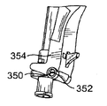
図38〜図40は、シールドを針保護位置に固定するフックの代替的な形態を示す。図38及び図39を参照すると、フック400が、側方に延びる屈曲部分402(図39)を含む。また、フック400は、シールド404が針保護位置に達すると、前述の実施形態におけるように針140にではなく、ハブ408の遠位の円筒形部分406に係合するように、シールド404の或る場所に位置付けられる。図40を参照すると、フック410が、近位に延びる屈曲部分412を含む。ハブ416の遠位の円筒形部分414が、シールド420が針保護位置に達するとフック410がフィン418に係合するように、十分な距離だけ長手方向に延びるフィン418を含む。
38-40 show an alternative form of hook that secures the shield in the needle protected position. Referring to FIGS. 38 and 39, the
上記の記載は、本ヒンジ式シールドアセンブリを実施するために意図された最良の形態を提示し、且つそれらを製造及び使用する方法及びプロセスの最良の形態を提示しており、それらが関係するいかなる当業者もこれらのヒンジ式シールドアセンブリを製造及び使用することを可能にするのに十分な、明確な、簡潔な、かつ正確な言葉で提示している。しかしながら、これらのヒンジ式シールドアセンブリは、上述したもの及び十分に等価なものに対する変形物及び代替的な構成が可能である。結果として、これらのヒンジ式シールドアセンブリは、開示されている特定の実施形態に限定されない。反対に、これらのヒンジ式シールドアセンブリは、ヒンジ式シールドアセンブリの主題を特に指摘し明確に特許請求する添付の特許請求の範囲によって概ね示されるような、ヒンジ式シールドアセンブリの精神及び範囲内にある全ての変形物及び代替的な構成物を包含する。 The above description presents the best mode contemplated for practicing the present hinged shield assembly, and presents the best mode of process and process for making and using them, and any Those skilled in the art also present in clear, concise and accurate language sufficient to allow these hinged shield assemblies to be manufactured and used. However, these hinged shield assemblies are capable of variations and alternative configurations to those described above and fully equivalent. As a result, these hinged shield assemblies are not limited to the specific embodiments disclosed. On the contrary, these hinged shield assemblies are within the spirit and scope of a hinged shield assembly, as generally indicated by the appended claims, which particularly point out and explicitly claim the subject matter of the hinged shield assembly. Includes all variations and alternative constructions.
Claims (24)
第1のソケットと第2のソケットを形成する第1のヒンジ部分を備える針ハブであって、前記針ハブから前記針が延びる、針ハブと、
前記シールドを前記ハブに枢動可能に固定するように前記第1のソケットに係合する第1のボールと前記第2のソケットに係合する第2のボールを形成する第2のヒンジ部分を備えるシールドであって、前記シールドは、前記シールドアセンブリが保護位置にあるときに前記針を部分的に囲むように構成されている複数の側壁を更に含み、前記複数の側壁は前記第1のボールを有する第1の側壁と前記第2のボールを有する第2の側壁と、前記第1の側壁と前記第2の側壁の間に配置された中央壁とを含む、シールドと、を備え、
前記第1のソケットと前記第2のソケットはそれぞれ開口を有し、
前記開口の径は、前記開口の内側に向かって大きくなり最大径部となり、さらに、前記最大径部から内側に向かって小さくなり小径部となり、
前記第1のボールと前記第2のボールはそれぞれ、前記第1のソケットと前記第2のソケットのそれぞれの前記最大径にほぼ等しく且つ前記開口の径よりも大きな径を有し、
前記第1のボールが前記第1のソケットに着座して前記第1のソケットからの引き出しに抵抗し、前記第2のボールが前記第2のソケットに着座して前記第2のソケットからの引き出しに抵抗する、ヒンジ式シールドアセンブリ。 A hinged shield assembly configured to shield a needle to prevent needle stick when using a hypodermic syringe, the assembly comprising:
A needle hub comprising a first hinge portion forming a first socket and a second socket, the needle hub extending from the needle hub;
A second hinge portion forming a first ball engaging the first socket and a second ball engaging the second socket to pivotally secure the shield to the hub; A shield comprising: a plurality of sidewalls configured to partially surround the needle when the shield assembly is in a protected position, the plurality of sidewalls being the first ball; A shield comprising: a first side wall having a second side wall having the second ball; and a central wall disposed between the first side wall and the second side wall;
Each of the first socket and the second socket has an opening;
The diameter of the opening increases toward the inside of the opening and becomes a maximum diameter portion, and further decreases from the maximum diameter portion toward the inside to become a small diameter portion.
Each of the first ball and the second ball has a diameter substantially equal to the maximum diameter of each of the first socket and the second socket and larger than a diameter of the opening;
The first ball is seated in the first socket to resist withdrawal from the first socket, and the second ball is seated in the second socket and pulled out from the second socket Hinged shield assembly that resists
前記第1の側壁と前記中央壁との間で前記ベースに第1のスリットが設けられており、
前記第2の側壁と前記中央壁との間で前記ベースに第2のスリットが設けられており、
前記第1のスリットと前記第2のスリットにより、前記第1の側壁と前記第2の側壁は互いに反対の方向に曲がり、前記針ハブに前記シールドが容易に取り付けられるようになっている、請求項1に記載のヒンジ式シールドアセンブリ。 The shield has a base;
A first slit is provided in the base between the first side wall and the central wall;
A second slit is provided in the base between the second side wall and the central wall;
The first slit and the second slit cause the first side wall and the second side wall to bend in opposite directions so that the shield is easily attached to the needle hub. Item 2. The hinged shield assembly according to item 1.
前記第1のボールと前記第2のボールはそれぞれ、ラチェットのような効果を得るために、それらに形成された平坦な表面を有する、請求項1に記載のヒンジ式シールドアセンブリ。 The first ball and the second ball are spaced from each other by a gap;
The hinged shield assembly of claim 1, wherein the first ball and the second ball each have a flat surface formed on them for a ratchet-like effect.
前記第1のヒンジ部分は、前記第1のソケットと前記第2のソケットとを備えた円筒形部分を有する、請求項1に記載のヒンジ式シールドアセンブリ。 A lateral base portion adjacent to one end of the first hinge portion;
The hinged shield assembly of claim 1, wherein the first hinge portion includes a cylindrical portion with the first socket and the second socket.
前記第2のボールは前記第2の側壁の第2のコーナーに配置されており、
前記第1の側壁の前記第1のコーナーと前記第2の側壁の前記第2のコーナーにそれぞれタブが配置されている、請求項2に記載のヒンジ式シールドアセンブリ。 The first ball is disposed at a first corner of the first sidewall;
The second ball is disposed at a second corner of the second sidewall;
The hinged shield assembly according to claim 2, wherein tabs are disposed at the first corner of the first sidewall and the second corner of the second sidewall, respectively.
針ハブとシールドとを含み、前記シールドは、前記シールドアセンブリが保護位置にあるときに前記針を部分的に囲むように構成されている複数の側壁を更に含み、
前記複数の側壁は、第1の側壁と、第2の側壁と、前記第1の側壁と前記第2の側壁の間に配置された中央壁を有し、
前記方法は、
第1のソケットと第2のソケットを備えた第1のヒンジ部分を有する円筒部を具備する横方向ベース部を備えた前記針ハブを形成することと、
前記第1の側壁に設けられた第1のボールと前記第2の側壁に設けられた第2ボールを備えた第2のヒンジ部分を有する前記シールドを形成することと、
前記第1のボールを前記第1のソケットに係合するとともに前記第2のボールを前記第2のソケットに係合して前記シールドを前記ハブに枢動可能に固定するように前記第1のヒンジ部分及び前記第2のヒンジ部分を互いに係合させることと、
を備え、
前記第1のソケットと前記第2のソケットはそれぞれ開口を有し、
前記開口の径は、前記開口の内側に向かって大きくなり最大径部となり、さらに、前記最大径部から内側に向かって小さくなり小径部となり、
前記第1のボールと前記第2のボールはそれぞれ、前記第1のソケットと前記第2のソケットのそれぞれの前記最大径にほぼ等しく且つ前記開口の径よりも大きな径を有し、
前記第1のボールが前記第1のソケットに着座して前記第1のソケットからの引き出しに抵抗し、前記第2のボールが前記第2のソケットに着座して前記第2のソケットからの引き出しに抵抗する、ヒンジ式シールドアセンブリを製造する方法。 A method of manufacturing a hinged shield assembly configured to shield a needle to prevent needle stick during use of a hypodermic syringe, the assembly comprising:
A needle hub and a shield, wherein the shield further includes a plurality of sidewalls configured to partially surround the needle when the shield assembly is in a protected position;
The plurality of side walls have a first side wall, a second side wall, and a central wall disposed between the first side wall and the second side wall,
The method
Forming the needle hub with a transverse base comprising a cylindrical portion having a first hinge portion with a first socket and a second socket;
Forming the shield having a second hinge portion with a first ball provided on the first side wall and a second ball provided on the second side wall;
The first ball engages the first socket and the second ball engages the second socket to pivotally secure the shield to the hub. Engaging the hinge portion and the second hinge portion with each other;
With
Each of the first socket and the second socket has an opening;
The diameter of the opening increases toward the inside of the opening and becomes a maximum diameter portion, and further decreases from the maximum diameter portion toward the inside to become a small diameter portion.
Each of the first ball and the second ball has a diameter substantially equal to the maximum diameter of each of the first socket and the second socket and larger than a diameter of the opening;
The first ball is seated in the first socket to resist withdrawal from the first socket, and the second ball is seated in the second socket and pulled out from the second socket A method of manufacturing a hinged shield assembly that resists resistance.
前記シールドは、前記第1のボールと前記第1のソケットと前記第2のボールと前記第2のソケットの間の緩衝によって前記第1位置に保持される、請求項13の方法。 Rotating the shield to a first position away from the needle;
14. The method of claim 13, wherein the shield is held in the first position by a buffer between the first ball, the first socket, the second ball, and the second socket.
前記第1の側壁と前記中央壁の間で前記ベースに第1のスリットが設けられ、
前記第2の側壁と前記中央壁の間で前記ベースに第2のスリットが設けられ、
前記第1のスリットと前記第2のスリットにより、前記第1の側壁と前記第2の側壁は互いに反対の方向に曲がり、前記針ハブに前記シールドが容易に取り付けられるようになっている、請求項13の方法。 The shield has a base;
A first slit is provided in the base between the first side wall and the central wall;
A second slit is provided in the base between the second side wall and the central wall;
The first slit and the second slit cause the first side wall and the second side wall to bend in opposite directions so that the shield is easily attached to the needle hub. Item 14. The method according to Item 13.
前記方法は、
前記シールドを前記針ハブに枢動可能に固定するヒンジを中心に前記針ハブに対して前記シールドを枢動させることと、
保護位置において、前記側壁が前記針を部分的に囲むまで前記針ハブに対して前記シールドを枢動させ続けることと、
前記保護位置において、前記針ハブに対して又は前記針に対して前記シールドをロックすることと、を備え、
前記ヒンジを中心に前記針ハブに対して前記シールドを枢動させることは、第1のソケット内で前記第1の側壁に配置された第1のボールを枢動させることと、第2のソケット内で前記第2の側壁に配置された第2のボールを枢動させることとを備えており、
前記第1のソケットと前記第2のソケットは横方向ベース部に配置されており、
前記第1のソケットと前記第2のソケットはそれぞれ開口を有し、
前記開口の径は、前記開口の内側に向かって大きくなり最大径部となり、さらに、前記最大径部から内側に向かって小さくなり小径部となり、
前記第1のボールと前記第2のボールはそれぞれ、前記第1のソケットと前記第2のソケットのそれぞれの前記最大径にほぼ等しく且つ前記開口の径よりも大きな径を有し、
前記第1のボールが前記第1のソケットに着座して前記第1のソケットからの引き出しに抵抗し、前記第2のボールが前記第2のソケットに着座して前記第2のソケットからの引き出しに抵抗する、ヒンジ式シールドアセンブリを使用する方法。 A method of using a hinged shield assembly that shields a needle to prevent needle stick when using a hypodermic syringe, the assembly including a needle hub and a shield, the shield further including a plurality of sidewalls, The plurality of sidewalls includes a first sidewall, a second sidewall, a central wall disposed between the first sidewall and the second sidewall,
The method
Pivoting the shield relative to the needle hub about a hinge pivotally securing the shield to the needle hub;
Continuing to pivot the shield relative to the needle hub in a protected position until the side wall partially surrounds the needle;
Locking the shield against the needle hub or against the needle in the protected position,
Pivoting the shield with respect to the needle hub about the hinge pivots a first ball disposed on the first side wall within the first socket; and a second socket Pivoting a second ball disposed on the second side wall,
The first socket and the second socket are disposed on a lateral base;
Each of the first socket and the second socket has an opening;
The diameter of the opening increases toward the inside of the opening and becomes a maximum diameter portion, and further decreases from the maximum diameter portion toward the inside to become a small diameter portion.
Each of the first ball and the second ball has a diameter substantially equal to the maximum diameter of each of the first socket and the second socket and larger than a diameter of the opening;
The first ball is seated in the first socket to resist withdrawal from the first socket, and the second ball is seated in the second socket and pulled out from the second socket How to use a hinged shield assembly that resists
前記第1のボールと前記第2のボールはそれぞれそれらに形成された平坦な表面を有する、請求項19に記載の方法。 The first ball and the second ball are spaced from each other by a gap;
20. The method of claim 19, wherein the first ball and the second ball each have a flat surface formed on them.
前記円筒形部分は、傾斜リムを備えた前記第1のソケットと前記第2のソケットとを有する、請求項19に記載の方法。 The hinge portion has a cylindrical portion disposed on the lateral base portion;
The method of claim 19, wherein the cylindrical portion comprises the first socket and the second socket with an inclined rim.
第1のタブが前記第1の側壁から伸びるとともに第2のタブが前記第2の側壁から伸びて、前記保護位置に前記針ハブの前記横方向ベース部に形成されたノッチと係合する、請求項21に記載の方法。 The sidewall has a first sidewall and a second sidewall,
A first tab extends from the first side wall and a second tab extends from the second side wall to engage a notch formed in the lateral base portion of the needle hub in the protected position; The method of claim 21.
前記フックは、前記保護位置で前記針に係合する大きさと形をしている、請求項22に記載の方法。 The hook extends from the central side wall,
23. The method of claim 22, wherein the hook is sized and shaped to engage the needle in the protected position.
前記第1の側壁と前記中央壁の間で前記ベースに第1のスリットが設けられ、
前記第2の側壁と前記中央壁の間で前記ベースに第2のスリットが設けられ、
前記第1のスリットと前記第2のスリットにより、前記第1の側壁と前記第2の側壁は互いに反対の方向に曲がり、前記針ハブに前記シールドが容易に取り付けられるようになっている、請求項19の方法。 The shield has a base;
A first slit is provided in the base between the first side wall and the central wall;
A second slit is provided in the base between the second side wall and the central wall;
The first slit and the second slit cause the first side wall and the second side wall to bend in opposite directions so that the shield is easily attached to the needle hub. Item 19. The method according to Item 19.
Applications Claiming Priority (3)
| Application Number | Priority Date | Filing Date | Title |
|---|---|---|---|
| US41625710P | 2010-11-22 | 2010-11-22 | |
| US61/416,257 | 2010-11-22 | ||
| PCT/US2011/061825 WO2012071400A2 (en) | 2010-11-22 | 2011-11-22 | Hinged shield assemblies and related methods |
Publications (3)
| Publication Number | Publication Date |
|---|---|
| JP2013545548A JP2013545548A (en) | 2013-12-26 |
| JP2013545548A5 JP2013545548A5 (en) | 2015-01-15 |
| JP6139409B2 true JP6139409B2 (en) | 2017-05-31 |
Family
ID=46146388
Family Applications (1)
| Application Number | Title | Priority Date | Filing Date |
|---|---|---|---|
| JP2013541017A Expired - Fee Related JP6139409B2 (en) | 2010-11-22 | 2011-11-22 | Hinged shield assembly and associated method |
Country Status (7)
| Country | Link |
|---|---|
| US (1) | US10639430B2 (en) |
| JP (1) | JP6139409B2 (en) |
| CN (1) | CN103269740A (en) |
| BR (1) | BR112013012582A2 (en) |
| DE (1) | DE112011103856T5 (en) |
| RU (1) | RU2584388C2 (en) |
| WO (1) | WO2012071400A2 (en) |
Families Citing this family (10)
| Publication number | Priority date | Publication date | Assignee | Title |
|---|---|---|---|---|
| WO2012071400A2 (en) | 2010-11-22 | 2012-05-31 | B. Braun Melsungen Ag | Hinged shield assemblies and related methods |
| AU2012218684B2 (en) * | 2011-02-14 | 2016-09-08 | Terumo Kabushiki Kaisha | Safety needle assembly |
| WO2016002389A1 (en) * | 2014-07-02 | 2016-01-07 | テルモ株式会社 | Safety needle assembly |
| CN104399157A (en) * | 2014-10-14 | 2015-03-11 | 汪贤宗 | General safety protective jacket |
| US20160158458A1 (en) * | 2014-12-07 | 2016-06-09 | Wuxi Yushou Medical Appliances Co., Ltd. | Safe Injection Device Capable of Locking Needle |
| US10029049B2 (en) * | 2015-03-19 | 2018-07-24 | B. Braun Melsungen Ag | Hinged shield assemblies and related methods |
| US11577766B2 (en) * | 2017-05-09 | 2023-02-14 | Brian Horowitz | Folding wagon |
| JP7246369B2 (en) * | 2018-03-16 | 2023-03-27 | テルモ株式会社 | Intradermal needle, package thereof, and injection device |
| JP2022537671A (en) * | 2019-06-21 | 2022-08-29 | ベクトン ディキンソン フランス | Safety device to prevent needlestick injuries from medical injection device needles |
| CN111744077A (en) * | 2020-06-05 | 2020-10-09 | 王素荣 | Angina pectoris alleviating and treating device for cardiovascular internal medicine |
Family Cites Families (160)
| Publication number | Priority date | Publication date | Assignee | Title |
|---|---|---|---|---|
| US3841769A (en) * | 1972-10-24 | 1974-10-15 | W Bowerman | Angularly adjustable bracket |
| US4049231A (en) * | 1976-01-07 | 1977-09-20 | Michael Lutz | Mold for manufacturing an integrally molded ball and socket type hinge |
| US4620813A (en) * | 1984-10-09 | 1986-11-04 | Burroughs Corporation | Position retaining mechanism |
| JPS61158584A (en) * | 1984-12-28 | 1986-07-18 | 株式会社北村鉄工所 | Production of hinge and product |
| USRE36447E (en) | 1985-07-29 | 1999-12-14 | Btg International Limited | Safety device for hypodermic needle or the like |
| US5536257A (en) | 1986-07-23 | 1996-07-16 | British Technology Group Ltd. | Safety device for hypodermic needle or the like |
| US4886503A (en) | 1988-05-23 | 1989-12-12 | University Medical Center, Inc. | Disposable covered needle for syringe |
| IT215091Z2 (en) | 1988-12-16 | 1990-07-30 | Memo Spa | HINGE WITH ADJUSTABLE ARTICULATION AXIS |
| US5011475A (en) | 1989-06-02 | 1991-04-30 | Olson Richard A | Protector for intravenous and syringe needles |
| EP0433250A3 (en) | 1989-12-15 | 1992-01-22 | Ippocrate S.R.L. | Disposable syringe |
| US4982842A (en) | 1990-06-04 | 1991-01-08 | Concord/Portex | Safety needle container |
| US5139489A (en) | 1991-01-07 | 1992-08-18 | Smiths Industries Medical Systems, Inc. | Needle protection device |
| US5232454A (en) | 1990-08-01 | 1993-08-03 | Smiths Industries Medical Systems, Inc. | Safety needle container |
| US5232455A (en) | 1991-01-07 | 1993-08-03 | Smiths Industries Medical Systems, Inc. | Syringe with protective housing |
| SE9101102D0 (en) | 1991-04-11 | 1991-04-11 | Viggo Spectramed Ab | NEEDLE PROTECTION DEVICE |
| US5370628A (en) | 1991-07-31 | 1994-12-06 | Allison; Alan C. | Safety needle and syringe |
| US5277311A (en) | 1991-12-20 | 1994-01-11 | Smiths Industries Medical Systems, Inc. | Needle assembly holder with rotatable safety sheath member and method of effecting proper alignment of a cannula using such needle assembly holder |
| USRE37110E1 (en) | 1992-05-18 | 2001-03-27 | William H. Hollister | Locking safety needle protection system |
| AU669722B2 (en) | 1992-05-18 | 1996-06-20 | Smiths Industries Medical Systems, Inc. | Safety needle protection system |
| US5615771A (en) | 1992-05-18 | 1997-04-01 | Smiths Industries Medical Systems, Inc. | Safety needle cartridge system |
| US5993426A (en) | 1993-04-16 | 1999-11-30 | Sims Portex Inc. | Fluid absorbable needle sheath |
| US5423765A (en) | 1993-05-06 | 1995-06-13 | Smiths Industries Medical Systems, Inc. | Removable safety needle sheath |
| US5693022A (en) | 1993-05-21 | 1997-12-02 | Haynes-Miller | Protective shield for hypodermic syringe |
| US5312368A (en) | 1993-05-21 | 1994-05-17 | Haynes-Miller, Inc. | Protective shield for hypodermic syringe |
| US5417659A (en) | 1993-07-20 | 1995-05-23 | Devon Industries, Inc. | Surgical instrument sharp end foil |
| US5385551A (en) | 1993-09-22 | 1995-01-31 | Shaw; Thomas J. | Nonreusable medical device with front retraction |
| US5419766A (en) | 1993-09-28 | 1995-05-30 | Critikon, Inc. | Catheter with stick protection |
| US5423758A (en) | 1993-12-16 | 1995-06-13 | Shaw; Thomas J. | Retractable fluid collection device |
| US5389076A (en) | 1994-04-05 | 1995-02-14 | Shaw; Thomas J. | Single use medical device with retraction mechanism |
| US5588767A (en) * | 1994-05-05 | 1996-12-31 | Merlo; Werner O. | Locking joint mechanism |
| US5466223A (en) | 1994-06-20 | 1995-11-14 | Becton, Dickinson And Company | Needle assembly having single-handedly activatable needle barrier |
| US5490841A (en) | 1994-07-29 | 1996-02-13 | Landis; Robert M. | Safety sheath device |
| US5433711A (en) | 1994-08-01 | 1995-07-18 | Monsanto Company | Syringe with cannula-protecting sheath and sealing center rod |
| US5423766A (en) | 1994-08-26 | 1995-06-13 | Becton, Dickinson And Company | Safety shield having spring tether |
| US5487733A (en) | 1994-09-20 | 1996-01-30 | Becton, Dickinson And Company | Assembly with collapsible sheath and tip guard |
| CA2157999C (en) | 1994-09-23 | 1999-08-03 | Robert B. Odell | Manually pivoted barrier assembly for a piercing element |
| US5643219A (en) | 1994-09-23 | 1997-07-01 | Burns; James A. | Shielded needle assembly |
| GB9419316D0 (en) | 1994-09-24 | 1994-11-09 | Robertson William F | A needle guard |
| US5823997A (en) | 1995-01-10 | 1998-10-20 | Specialized Health Products, Inc. | Medical needle safety apparatus and methods |
| US5599313A (en) | 1995-02-03 | 1997-02-04 | Becton, Dickinson And Company | Needle shield assembly having safety indication features |
| US5885249A (en) | 1995-04-06 | 1999-03-23 | Nifco Inc. | Syringe with cap |
| US5584816A (en) | 1995-05-25 | 1996-12-17 | Becton, Dickinson And Company | Hardpack shield for a pivoting needle guard |
| US5743888A (en) | 1995-08-01 | 1998-04-28 | Kaleva Design | Safety needle |
| US5599318A (en) * | 1995-08-29 | 1997-02-04 | Becton, Dickinson And Company | Needle shield assembly having a releasable lock |
| US5603699A (en) | 1996-02-07 | 1997-02-18 | Shine; Jerry P. | Needle guard assembly |
| US5509907A (en) | 1996-03-17 | 1996-04-23 | Med-Safe Products, Inc. | Syringe needle guard assembly |
| US5704920A (en) | 1996-05-17 | 1998-01-06 | Becton, Dickinson And Company | Manually driven needle shield assembly |
| US5913846A (en) | 1996-06-13 | 1999-06-22 | Becton, Dickinson And Company | Shielded needle assembly |
| US5807351A (en) | 1996-06-17 | 1998-09-15 | Safegard Medical Products, Inc. | Protection device for sharp objects |
| US5669889A (en) | 1996-07-03 | 1997-09-23 | Becton, Dickinson And Company | Needle shield assembly having a single-use lock |
| US5681295A (en) | 1996-07-03 | 1997-10-28 | Becton, Dickinson And Company | Needle shield assembly having a single-use cannula lock |
| US5746726A (en) | 1996-08-23 | 1998-05-05 | Becton, Dickinson And Company | Shielded needle assembly |
| US5632732A (en) | 1996-09-11 | 1997-05-27 | Becton, Dickinson And Company | Needle assembly having single handedly activated shield |
| US5733265A (en) | 1996-09-25 | 1998-03-31 | Becton Dickinson And Company | Shielded needle assembly |
| US5810775A (en) | 1997-05-23 | 1998-09-22 | Shaw; Thomas J. | Cap operated retractable medical device |
| CA2240338A1 (en) | 1997-06-23 | 1998-12-23 | Becton, Dickinson And Company | Shielded needle assembly |
| US7125397B2 (en) | 1997-08-20 | 2006-10-24 | B. Braun Melsungen Ag | Protective device for an injection needle |
| US5919165A (en) | 1997-09-26 | 1999-07-06 | Becton, Dickinson And Company | Rotatable needle shield for needle cannula |
| JP3171154B2 (en) | 1997-10-22 | 2001-05-28 | 松下電器産業株式会社 | Storage device |
| US6120480A (en) | 1997-10-28 | 2000-09-19 | Medtronic Ave, Inc. | Catheter introducer |
| US5957892A (en) | 1998-03-12 | 1999-09-28 | Specialized Health Products, Inc. | Safety catheter insertion apparatus and methods |
| JPH11299692A (en) | 1998-04-20 | 1999-11-02 | Toto Ltd | Toilet lid device |
| US6355021B1 (en) | 1998-07-14 | 2002-03-12 | Maersk Medical A/S | Medical puncturing device |
| US6440104B1 (en) | 1998-08-28 | 2002-08-27 | Becton, Dickinson And Company | Safety shield assembly |
| US20030187399A1 (en) | 2002-04-02 | 2003-10-02 | Becton, Dickinson And Company | Safety shield assembly |
| US6436086B1 (en) | 1998-08-28 | 2002-08-20 | Becton Dickinson And Company | Method of using a safety shield assembly and related combinations thereof |
| US7223258B2 (en) | 1998-08-28 | 2007-05-29 | Becton Dickinson And Company | Safety shield assembly |
| US6298541B1 (en) | 1998-08-28 | 2001-10-09 | Becton, Dickinson And Company | Method for making a safety shield assembly and related combinations thereof |
| US20020072715A1 (en) * | 1998-08-28 | 2002-06-13 | Newby C. Mark | Needle assembly |
| US6334857B1 (en) | 1999-01-11 | 2002-01-01 | Sims Portex Inc. | Needle protection apparatus used with a vial |
| US6042570A (en) | 1999-02-11 | 2000-03-28 | Dsu Medical Corporation | Needle point protection sheath |
| US6096024A (en) | 1999-02-12 | 2000-08-01 | Becton Dickinson And Company | Blunt needle connector |
| US6149629A (en) | 1999-05-14 | 2000-11-21 | Specialized Health Products, Inc. | Medical needle safety apparatus and methods |
| US6699217B2 (en) | 1999-08-23 | 2004-03-02 | Becton, Dickinson And Company | Safety needle assembly |
| US6648855B2 (en) | 1999-08-23 | 2003-11-18 | Becton, Dickinson And Company | Safety needle assembly |
| US6780169B2 (en) | 1999-08-23 | 2004-08-24 | Becton, Dickinson And Company | Safety shield assembly |
| US6254575B1 (en) | 1999-11-04 | 2001-07-03 | Specialized Health Products | Reaccessible medical needle safety devices and methods |
| US7029461B2 (en) | 1999-11-04 | 2006-04-18 | Tyco Healthcare Group Lp | Safety shield for medical needles |
| US7198618B2 (en) | 1999-11-04 | 2007-04-03 | Tyco Healthcare Group Lp | Safety shield for medical needles |
| US6592556B1 (en) | 2000-07-19 | 2003-07-15 | Tyco Healthcare Group Lp | Medical needle safety apparatus and methods |
| US8226617B2 (en) | 1999-11-04 | 2012-07-24 | Tyco Healthcare Group Lp | Safety shield apparatus and mounting structure for use with medical needle devices |
| US6280420B1 (en) | 1999-11-04 | 2001-08-28 | Specialized Health Products | Reaccessible medical needle safety devices and methods |
| US6517522B1 (en) | 2000-04-03 | 2003-02-11 | Dsu Medical Corporation | Tubular intravenous set |
| US6524281B1 (en) | 2000-04-14 | 2003-02-25 | Portex, Inc. | Needle protection device for use with a vial |
| US6616638B2 (en) | 2000-06-19 | 2003-09-09 | Craig J. Bell | Hypodermic needle cap and sharps protective cap ejector |
| JP2002102344A (en) | 2000-10-02 | 2002-04-09 | Terumo Corp | Puncture tool |
| IT1318365B1 (en) | 2000-11-21 | 2003-08-25 | Cgm Spa | PROTECTION DEVICE FOR NEEDLE FOR SYRINGE FOR MEDICAL USE. |
| WO2002070056A1 (en) * | 2001-03-02 | 2002-09-12 | Sherwood Services Ag | Passive safety shield |
| AU3708902A (en) | 2001-05-04 | 2002-11-07 | Becton Dickinson & Company | Passively activated safely needle |
| US6561476B2 (en) * | 2001-05-14 | 2003-05-13 | Jeffrey D. Carnevali | Positively-positionable mounting apparatus |
| DE60238007D1 (en) | 2001-05-22 | 2010-11-25 | Dickinson & Co | Needle guard assembly with hinged needle guard |
| JP4478448B2 (en) | 2001-06-06 | 2010-06-09 | ベクトン・ディキンソン・アンド・カンパニー | Hinge needle shield assembly with needle cannula lock |
| US6582397B2 (en) | 2001-06-19 | 2003-06-24 | Portex, Inc. | Needle safety device with antiremoval protection |
| MXPA04000177A (en) | 2001-07-09 | 2004-03-18 | Becton Dickinson Co | Needle shield assembly having hinged needle shield and flexible cannula lock. |
| CN2501513Y (en) | 2001-07-31 | 2002-07-24 | 段如英 | Syringe needle protective cover |
| US6869418B2 (en) | 2001-08-17 | 2005-03-22 | Hypoguard Usa Inc. | Safety shield for a needle assembly |
| US7488306B2 (en) | 2001-09-26 | 2009-02-10 | Smiths Medical Asd, Inc. | Needle protection device with dampener |
| US6695819B2 (en) | 2001-10-19 | 2004-02-24 | Terumo Medical Corporation | Safety needle assembly |
| US20030125676A1 (en) | 2001-12-28 | 2003-07-03 | Becton, Dickinson And Company | Medical needle assemblies |
| US20040054334A1 (en) | 2001-12-28 | 2004-03-18 | Prais Alfred W. | Medical needle assemblies |
| CA2475169C (en) | 2002-02-12 | 2011-04-12 | Unomedical A/S | Infusion device with needle shield |
| CA2422521A1 (en) | 2002-03-20 | 2003-09-20 | Kirk D. Swenson | Needle shield assembly |
| AU2003201335B2 (en) | 2002-03-20 | 2009-07-23 | Becton, Dickinson And Company | Shieldable needle assembly with biased safety shield |
| CA2422307A1 (en) | 2002-03-20 | 2003-09-20 | Stefanie Livanos | Blood collection device |
| ES2240875T3 (en) | 2002-03-21 | 2005-10-16 | Becton, Dickinson And Company | SAFETY NEEDLE DEVICE WITH A Dorsal FIN. |
| US20030187398A1 (en) | 2002-04-02 | 2003-10-02 | Becton, Dickinson And Company | Safety shield assembly |
| US7001363B2 (en) | 2002-04-05 | 2006-02-21 | F. Mark Ferguson | Safety shield for medical needles |
| US6719737B2 (en) | 2002-05-13 | 2004-04-13 | Terumo Medical Corporation | Safety needle assembly |
| US20030220618A1 (en) | 2002-05-24 | 2003-11-27 | Becton Dickinson And Company | Safety shield assembly |
| SG121744A1 (en) | 2002-11-06 | 2006-05-26 | Becton Dickinson Co | Flashback blood collection needle with needle shield |
| EP1380315A1 (en) | 2002-06-12 | 2004-01-14 | Becton, Dickinson and Company | Safety needle assembly |
| US6811547B2 (en) | 2002-07-22 | 2004-11-02 | Becton, Dickinson & Company | Needle shielding assembly |
| MXPA05003837A (en) | 2002-10-11 | 2005-06-22 | Becton Dickinson Co | Single use syringe having safety shield. |
| US6921388B2 (en) | 2002-11-04 | 2005-07-26 | Becton Dickinson Co | Needle assembly |
| US8231583B2 (en) | 2002-12-04 | 2012-07-31 | Becton, Dickinson And Company | Safety needle assembly with passive pivoting shield |
| JP4511946B2 (en) | 2002-12-16 | 2010-07-28 | ベクトン・ディキンソン・アンド・カンパニー | Safety needle assembly |
| AT413947B (en) | 2003-01-27 | 2006-07-15 | Greiner Bio One Gmbh | MEDICAL ASSEMBLY, AND A PROTECTION DEVICE, AN ARTICLE AND HANDLING DEVICE FOR THIS MODULE |
| US7553296B2 (en) | 2003-02-14 | 2009-06-30 | Tyco Healthcare Group Lp | Safety device with trigger mechanism |
| US7722572B2 (en) | 2003-05-28 | 2010-05-25 | Terumo Kabushiki Kaisha | Safety needle assembly |
| US6824531B1 (en) | 2003-07-14 | 2004-11-30 | Smiths Medical Asd, Inc. | Medicament container with needle protection housing |
| US20050027255A1 (en) | 2003-07-31 | 2005-02-03 | Sid Technologies, Llc | Automatic injector |
| US7201736B2 (en) | 2003-08-28 | 2007-04-10 | Smiths Medical Asd, Inc. | Needle protection assembly |
| US7250038B2 (en) | 2003-09-09 | 2007-07-31 | Smiths Medical Asd, Inc. | Fixed needle syringe with protective needle housing |
| USD505200S1 (en) | 2003-09-09 | 2005-05-17 | Smiths Medical Asd, Inc. | Fixed needle assembly |
| US8251961B2 (en) | 2003-09-22 | 2012-08-28 | Smiths Medical Asd, Inc. | Safety needle assembly and method for making the same |
| US7322963B2 (en) | 2003-11-20 | 2008-01-29 | Jms Singapore Pte Ltd. | Telescopic safety arteriovenous fistula needle |
| US20050146081A1 (en) | 2004-01-07 | 2005-07-07 | Maclean David | Needle protection device with gauge specific color coding and method for manufacturing thereof |
| US8226576B2 (en) | 2004-02-25 | 2012-07-24 | Becton, Dickinson And Company | Safety blood collection holder |
| US7413560B2 (en) | 2004-04-15 | 2008-08-19 | Jms North America Corporation | Safety arteriovenous fistula needle |
| CN1254283C (en) * | 2004-04-20 | 2006-05-03 | 钱倚天 | Safeguard protection setting for expendable needle in use for medical treatment |
| DE602004029206D1 (en) | 2004-09-22 | 2010-10-28 | Smiths Medical Asd Inc | SAFETY ADAPTER FOR A NEEDLE APPROACH |
| JP4498124B2 (en) * | 2004-12-27 | 2010-07-07 | 株式会社ソミック石川 | Ball joint |
| CN2763429Y (en) * | 2004-12-31 | 2006-03-08 | 白宝鲲 | Hinge for side hang and double-open window and door |
| US8641680B2 (en) | 2005-01-06 | 2014-02-04 | Smiths Medical Asd, Inc. | Safety needle device with snap feature |
| US7648480B2 (en) | 2005-03-31 | 2010-01-19 | Terumo Medical Corporation | Safety needle assembly |
| US8016796B2 (en) | 2005-05-27 | 2011-09-13 | Smiths Medical Asd, Inc. | Safety needle device with snap feature and method of making same |
| US7635352B2 (en) | 2005-05-27 | 2009-12-22 | Becton, Dickinson And Company | Catheter and introducer needle assembly with needle shield |
| US20070088261A1 (en) | 2005-10-03 | 2007-04-19 | Lew Jung C | Hypodermic needle safety cap apparatus |
| US20070100296A1 (en) | 2005-10-31 | 2007-05-03 | Becton, Dickinson And Company | Single-handedly actuatable shield for needles |
| US7186240B1 (en) | 2005-10-31 | 2007-03-06 | Ivan Kronja | Safety needle assembly |
| DE102006013322A1 (en) | 2006-03-21 | 2007-09-27 | Sarstedt Ag & Co. | Canula has protective housing consisting of two sections plugged into each other, wherein inner housing has lamella pair, and outer housing is formed as sleeve which is less elastic with regard to inner housing |
| CA2667404A1 (en) | 2006-10-23 | 2008-05-02 | Sun Medical-Scientific (Shanghai) Co., Ltd. | Safety transfusion catheter |
| US8057431B2 (en) | 2006-12-21 | 2011-11-15 | B. Braun Melsungen Ag | Hinged cap for needle device |
| US7871397B2 (en) | 2006-12-26 | 2011-01-18 | Stat Medical Devices, Inc. | Pen needle tip |
| US8038654B2 (en) | 2007-02-26 | 2011-10-18 | Becton, Dickinson And Company | Syringe having a hinged needle shield |
| AP2952A (en) | 2007-07-12 | 2014-08-31 | Star Syringe Ltd | Needlestick prevention device |
| WO2009016234A1 (en) | 2007-08-01 | 2009-02-05 | Süddeutsche Feinmechanik GmbH | Cannula device having pivotable needle guard |
| US20090173330A1 (en) * | 2008-01-09 | 2009-07-09 | Kenneth Robert Akins | Paint ball loader housing |
| US8109910B2 (en) | 2008-02-14 | 2012-02-07 | Tyco Healthcare Group Lp | Flip-top design cannula |
| US7938800B2 (en) | 2008-05-13 | 2011-05-10 | Lawrence R. Koh and Nina Merrell-Koh | Needleshield assembly and methods of use |
| US7811261B2 (en) | 2008-06-02 | 2010-10-12 | Sta-Med, Llc | Needle cover assembly for a syringe |
| EP2355876B1 (en) | 2008-11-18 | 2016-01-27 | B. Braun Melsungen AG | Hinged shield assembly and related methods |
| EP2355871A4 (en) | 2008-11-18 | 2013-01-09 | Braun Melsungen Ag | Hinged cap for needle device |
| US8162882B2 (en) | 2010-06-23 | 2012-04-24 | Sta-Med, Llc | Automatic-locking safety needle covers and methods of use and manufacture |
| WO2012071400A2 (en) | 2010-11-22 | 2012-05-31 | B. Braun Melsungen Ag | Hinged shield assemblies and related methods |
| US8177063B1 (en) | 2010-12-29 | 2012-05-15 | Kendell A. Simm | Hypodermic needle holder |
| AU2012218684B2 (en) | 2011-02-14 | 2016-09-08 | Terumo Kabushiki Kaisha | Safety needle assembly |
| CN202724375U (en) | 2011-05-06 | 2013-02-13 | 上海萌黎国际贸易有限公司 | Safety needle assembly |
| RU2013154503A (en) | 2011-07-05 | 2015-08-10 | Вигмед Аб | PROTECTIVE DEVICE NEEDLE WITH ACTIVE CONDITION AND PASSIVE CONDITION |
| JP5993034B2 (en) | 2012-03-08 | 2016-09-14 | ベクトン・ディキンソン・アンド・カンパニーBecton, Dickinson And Company | Blood collection assembly with multi-function shield |
-
2011
- 2011-11-22 WO PCT/US2011/061825 patent/WO2012071400A2/en active Application Filing
- 2011-11-22 BR BR112013012582A patent/BR112013012582A2/en not_active Application Discontinuation
- 2011-11-22 RU RU2013128474/14A patent/RU2584388C2/en not_active IP Right Cessation
- 2011-11-22 CN CN201180056060XA patent/CN103269740A/en active Pending
- 2011-11-22 JP JP2013541017A patent/JP6139409B2/en not_active Expired - Fee Related
- 2011-11-22 DE DE112011103856T patent/DE112011103856T5/en not_active Withdrawn
- 2011-11-22 US US13/878,305 patent/US10639430B2/en active Active
Also Published As
| Publication number | Publication date |
|---|---|
| US20130274684A1 (en) | 2013-10-17 |
| WO2012071400A3 (en) | 2012-08-16 |
| RU2013128474A (en) | 2014-12-27 |
| JP2013545548A (en) | 2013-12-26 |
| BR112013012582A2 (en) | 2016-08-09 |
| WO2012071400A2 (en) | 2012-05-31 |
| US10639430B2 (en) | 2020-05-05 |
| DE112011103856T5 (en) | 2013-08-29 |
| CN103269740A (en) | 2013-08-28 |
| RU2584388C2 (en) | 2016-05-20 |
Similar Documents
| Publication | Publication Date | Title |
|---|---|---|
| JP6139409B2 (en) | Hinged shield assembly and associated method | |
| US10617830B2 (en) | Hinged shield assemblies and related methods | |
| JP6266517B2 (en) | Needle protector and safe needle assembly | |
| KR102133920B1 (en) | Needle shield puller cap assembly | |
| JP2022031554A (en) | System and method for safety syringe | |
| US20030125676A1 (en) | Medical needle assemblies | |
| US7632252B2 (en) | Medical needle assemblies | |
| US20110040317A1 (en) | Lancet block and lancet activating device | |
| US20200330676A1 (en) | Syringe holder for a medical injector and method of forming a medical injector assembly | |
| RU2756021C2 (en) | Device for preventing needle pricks | |
| TWM504606U (en) | Safety protective syringe | |
| US20220233786A1 (en) | Needle cover and safety needle assembly including same | |
| EP4212143A1 (en) | Connector assembly for medical injection device | |
| EP4212142A1 (en) | Vial adaptor providing audible feedback and connector assembly for medical injection device including vial adaptor | |
| WO2022182289A1 (en) | Connector assembly and manufacturing process of the same | |
| JP3107197U (en) | Safety syringe | |
| JP3877284B2 (en) | Medical tool holder |
Legal Events
| Date | Code | Title | Description |
|---|---|---|---|
| RD03 | Notification of appointment of power of attorney |
Free format text: JAPANESE INTERMEDIATE CODE: A7423 Effective date: 20131101 |
|
| RD04 | Notification of resignation of power of attorney |
Free format text: JAPANESE INTERMEDIATE CODE: A7424 Effective date: 20131202 |
|
| A521 | Written amendment |
Free format text: JAPANESE INTERMEDIATE CODE: A523 Effective date: 20141118 |
|
| A621 | Written request for application examination |
Free format text: JAPANESE INTERMEDIATE CODE: A621 Effective date: 20141118 |
|
| A977 | Report on retrieval |
Free format text: JAPANESE INTERMEDIATE CODE: A971007 Effective date: 20151016 |
|
| A131 | Notification of reasons for refusal |
Free format text: JAPANESE INTERMEDIATE CODE: A131 Effective date: 20151020 |
|
| A601 | Written request for extension of time |
Free format text: JAPANESE INTERMEDIATE CODE: A601 Effective date: 20160118 |
|
| A521 | Written amendment |
Free format text: JAPANESE INTERMEDIATE CODE: A523 Effective date: 20160219 |
|
| A131 | Notification of reasons for refusal |
Free format text: JAPANESE INTERMEDIATE CODE: A131 Effective date: 20160802 |
|
| A521 | Written amendment |
Free format text: JAPANESE INTERMEDIATE CODE: A523 Effective date: 20161102 |
|
| TRDD | Decision of grant or rejection written | ||
| A01 | Written decision to grant a patent or to grant a registration (utility model) |
Free format text: JAPANESE INTERMEDIATE CODE: A01 Effective date: 20170411 |
|
| A61 | First payment of annual fees (during grant procedure) |
Free format text: JAPANESE INTERMEDIATE CODE: A61 Effective date: 20170427 |
|
| R150 | Certificate of patent or registration of utility model |
Ref document number: 6139409 Country of ref document: JP Free format text: JAPANESE INTERMEDIATE CODE: R150 |
|
| LAPS | Cancellation because of no payment of annual fees |