EP2355876B1 - Hinged shield assembly and related methods - Google Patents
Hinged shield assembly and related methods Download PDFInfo
- Publication number
- EP2355876B1 EP2355876B1 EP09828048.0A EP09828048A EP2355876B1 EP 2355876 B1 EP2355876 B1 EP 2355876B1 EP 09828048 A EP09828048 A EP 09828048A EP 2355876 B1 EP2355876 B1 EP 2355876B1
- Authority
- EP
- European Patent Office
- Prior art keywords
- shield
- needle
- assembly
- shields
- hinged
- Prior art date
- Legal status (The legal status is an assumption and is not a legal conclusion. Google has not performed a legal analysis and makes no representation as to the accuracy of the status listed.)
- Not-in-force
Links
Images


Classifications
-
- A—HUMAN NECESSITIES
- A61—MEDICAL OR VETERINARY SCIENCE; HYGIENE
- A61M—DEVICES FOR INTRODUCING MEDIA INTO, OR ONTO, THE BODY; DEVICES FOR TRANSDUCING BODY MEDIA OR FOR TAKING MEDIA FROM THE BODY; DEVICES FOR PRODUCING OR ENDING SLEEP OR STUPOR
- A61M5/00—Devices for bringing media into the body in a subcutaneous, intra-vascular or intramuscular way; Accessories therefor, e.g. filling or cleaning devices, arm-rests
- A61M5/178—Syringes
- A61M5/31—Details
- A61M5/32—Needles; Details of needles pertaining to their connection with syringe or hub; Accessories for bringing the needle into, or holding the needle on, the body; Devices for protection of needles
- A61M5/3205—Apparatus for removing or disposing of used needles or syringes, e.g. containers; Means for protection against accidental injuries from used needles
- A61M5/321—Means for protection against accidental injuries by used needles
- A61M5/3216—Caps placed transversally onto the needle, e.g. pivotally attached to the needle base
Definitions
- the present invention relates generally to caps for needle devices, and more particularly to hinged cap devices for use with hypodermic needles.
- Recapping is a common procedure for periods between drawing up fluids into a syringe and administering injections through a needle.
- the recapping procedure can occasionally cause needlesticks since users sometime misalign the needles with the openings on the caps. Needlesticks can be painful, but can also cause great inconvenience because all needlesticks must be reported. Also, since needles related to needlesticks must be discarded, medications contained within the syringes are unnecessarily wasted. Furthermore, fluids linked to these "clean" type of needlesticks can cause injuries and adverse reactions.
- US 5 632 732 A relates to a shielded needle assembly having an elongate shield with a proximal end, a distal end and a sidewall with an elongate opening.
- the shield is operable between an open position, where the distal point of the needle is exposed for use by passage through the elongate opening; a closed position, where the shield substantially obstructs access to the needle; and a latched position, where the shield is closed and the elongate opening is substantially obstructed as well as being the shield being substantially prevented from inadvertent movement to the open position.
- US 6 413 243 B1 discloses an apparatus for covering a used hypodermic syringe needle comprising a base, a pair of covers mounted moveably to the base, and at least one latching member mounted to the base. The covers can be moved into a closed position over the needle.
- One embodiment of the present methods of shielding a needle to prevent needlesticks comprises rotating a first shield in a first direction with respect to a second shield.
- the method further comprises pivoting the first and second shields in a first direction with respect to the needle to expose a sharp distal tip of the needle.
- the method further comprises pivoting the first and second shields in a second direction with respect to the needle, opposite the first direction, until the needle is at least partially enclosed within the first and second shields.
- the method further comprises rotating the first shield in a second direction, opposite the first direction, with respect to the second shield.
- the method further comprises translating the first shield with respect to the second shield to lock the second shield against further rotational and translational motion with respect to the first shield.
- One embodiment of the present hinged shield assembly is configured to shield a needle to prevent needlesticks.
- the assembly comprises a base including a hinge, a first shield and a second shield.
- the first shield extends from the base and at least partially surrounds the second shield.
- the first and second shields are configured to pivot about the hinge, and a distal end of the first shield is open.
- the present hinged shield assembly is configured to shield a needle to prevent needlesticks.
- the assembly comprises a base including a hinge, a first shield and a second shield.
- the first shield extends from the base and at least partially surrounds the second shield.
- the first shield includes a sidewall and a channel extending along the sidewall in a direction parallel to a longitudinal axis of the first shield.
- the second shield includes a sidewall and a channel extending along the sidewall in a direction parallel to a longitudinal axis of the second shield.
- the first and second shields are configured to pivot about the hinge, and the first and second shields are rotatable with respect to one another such that the channels in each may be aligned.
- the present hinged shield assembly is configured to shield a needle to prevent needlesticks.
- the assembly comprises a base including first and second spaced flanges and a hinge.
- the assembly further comprises a first shield and a second shield.
- the first shield extends from the base and at least partially surrounds the second shield.
- the first and second shields are configured to pivot about the hinge, and the second shield includes a tab that is selectively disposable within a space defined between the first and second flanges.
- the assembly comprises a base including first and second spaced flanges and a hinge.
- the assembly further comprises a first shield and a second shield.
- the first shield extends from the base and at least partially surrounds the second shield.
- the first and second shields are configured to pivot about the hinge, and the second shield includes a tab that is selectively disposable within a channel that extends along a sidewall of the first shield in a direction parallel to a longitudinal axis of the first shield.
- the assembly comprises a base including first and second spaced flanges and a hinge.
- the assembly further comprises a first shield and a second shield.
- the first shield extends from the base and at least partially surrounds the second shield.
- the first and second shields are configured to pivot about the hinge, and the first and second shields are translatable and rotatable with respect to one another.
- FIGs 1-8 illustrate one embodiment of the present hinged shield assembly 30.
- the hinged shield assembly 30 cooperates with a syringe 32 ( Figures 1 and 2 ) to selectively shield 42 a needle 34 ( Figure 4 ) extending from a needle hub 36, which engages a distal end 38 of the syringe 32.
- the shield assembly 30 comprises a base 40 and a shield 42 that is pivotable about the base 40.
- the shield 42 is configured to be converted from a packaged or ready-to-use position ( Figures 5 and 6 ) to an open position ( Figure 3 ), and from the open position back to the ready-to-use position and then to a secured position ( Figures 7 and 8 ).
- the ready-to-use position may also be viewed as a temporary lock position because while it prevents the shield 42 from being rotated away from the needle, it can be switched to an open position to permit administration or aspiration of medication. However, a practitioner may leave the needle exposed after filling the syringe and before injecting a patient without moving back to the ready-to-use position.
- the base 40 comprises first and second spaced flanges 44, 46.
- the first flange 44 extends from the needle hub 36 in a direction substantially perpendicular to a longitudinal axis of the needle 34.
- the second flange 46 is substantially parallel to the first flange 44, and spaced from the first flange 44 in the distal direction (toward a sharp distal tip 48 of the needle 34 ( Figure 4 )).
- a wall section 50 connects the first and second flanges 44, 46 at edges thereof.
- a junction of the wall section 50 and the first flange 44 comprises a hinge 52.
- the shield assembly 30 is pivotable about the hinge 52 between the open position ( Figure 3 ) and an exposed needle position ( Figure 4 ), as described in further detail below.
- the shield assembly 30 may be made by injection molding.
- the base 40 may comprise a single piece, and the hinge 52 may comprise a relatively thin portion of injection-molded plastic, commonly referred to as a "living" hinge.
- the shield assembly 30 further may be integrally formed as a single unit with the needle hub 36.
- the shield assembly 30 may be formed separately and secured to the needle hub 36 by known methods, such as welding or mechanical engagement to convert a simple commercially available hypodermic needle into a safety needle assembly.
- the shield 42 extends from the second flange 46 in a direction away from the first flange 44.
- the shield 42 comprises a first or outer shield 54 and a second or inner shield 56.
- the first and second shields 54, 56 are rotatable and translatable with respect to one another.
- the second shield 56 is rotatable with respect to the first shield 54 from the ready-to-use position of Figure 5 to the open position of Figure 3 .
- the second shield 56 is further translatable with respect to the first shield 54 from the ready-to-use position of Figure 5 to the secured position of Figure 7 .
- the first shield 54 is shaped substantially as an elongate, hollow, circular cylinder including a sidewall 58.
- the sidewall 58 includes a channel 60 that, in the illustrated embodiment, extends in the longitudinal direction from the proximal end 62 to the distal end 64.
- the distal end 64 of the first shield 54 is open.
- the first shield 54 further includes a push tab 66 extending from the sidewall 58 opposite the channel 60.
- the push tab 66 provides a convenient surface for an operator to apply digital pressure to pivot the shield 42 between the open position ( Figure 3 ) and the exposed needle position ( Figure 4 ).
- the second shield 56 is shaped substantially as an elongate, hollow, circular cylinder including a sidewall 68.
- the sidewall 68 includes a channel 70 ( Figure 3 ) that, in the illustrated embodiment, extends in the longitudinal direction from the proximal end 72 to the distal end 74.
- the distal end 74 of the second shield 56 is closed, which is preferred although an open end may also be used.
- the second shield 56 as shown is of the same length as the first shield 54 in that the distal ends of the two shields are generally level or flush.
- the second shield 56 can be longer than the first shield 54 so that the distal end 74 of the second shield 56 protrudes out from the distal end 64 of the first shield 54 in the ready-to-use and open positions and is then at least level with the distal end 64 of the first shield 54 in the secure position.
- This difference provides a caregiver or user with a visual feedback thus enabling the user to more easily determine whether the shield 42 is in the ready-to-use or the secure position.
- the second shield 56 further includes a tab 76 at the proximal end 62 that extends outward in a direction substantially perpendicular to a longitudinal axis of the second shield 56. In the illustrated embodiment, the tab 76 is spaced approximately ninety-degrees from the channel 70 around the circumference of the second shield 56. However, as those of ordinary skill in the art will appreciate, the tab 76 may occupy substantially any position relative to the channel 70.
- the first shield 54 substantially surrounds the second shield 56.
- the second shield 56 is inserted into the first shield 54 through its open distal end 64 ( Figure 2 ) and translated toward the base 40 until it reaches the ready-to-use position of Figure 5 .
- the needle 34 is protected because the sidewall 68 of the second shield 56 interferes with the needle 34 if the shield 42 is pivoted about the hinge 52 ( Figure 6 ).
- the sidewall 68 of the inner shield blocks the channel 60 of the outer shield thus obstructing the path needed to pivot the shield 42 away from the needle.
- the syringe 32 and shield assembly 30 may be transported from the manufacturer to the customer in the ready-to-use position.
- the tab 76 provides a convenient surface upon which to apply digital pressure to translate the second shield 56 relative to the first shield 54. Comparing Figures 5 and 7 , digital pressure applied to the tab 76 in the direction of the arrow 78 translates the second shield 56 relative to the first shield 54 from the ready-to-use position of Figure 5 to the secured position of Figure 7 . In the secured position the first and second shields 54, 56 are locked against relative translation and rotation.
- the proximal end 72 of the second shield 56 includes a diametrically opposed slot 80 that cooperates with a rib 82 on the needle hub 36 to enable the second shield 56 to translate proximally relative to the first shield 54.
- aspects of the present invention include a provision for aligning sections of the first shield and the second shield for purposes of fixing the needle assembly in a secured position.
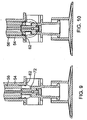
- Figures 9 and 10 show cross-sectional views of the proximal ends 62, 72 of the first and second shields 54, 56 in the ready-to-use position ( Figure 9 ) and the secured position ( Figure 10 ).
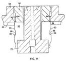
- Figure 11 shows an enlarged detail view of Figure 10 .
- An inner edge at the proximal end 62 of the first shield 54 comprises a detent 84 that engages a groove 86 in the second shield 56.
- a ledge 88 at the proximal end of the groove 86 engages the detent 84 to resist translation of the second shield 56 in the distal direction relative to the first shield 54.
- a tapered surface 90 at the distal end of the groove 86 engages the detent 84 to resist translation of the second shield 56 in the proximal direction relative to the first shield 54.
- the tapered surface 90 allows the second shield 56 to translate in the proximal direction relative to the first shield 54 when a threshold digital force is applied to the tab 76.
- Elastic deformation of the first and second shields 54, 56 enables the relatively larger second shield 56 proximal portion 92 to slide through the relatively smaller opening 94 at the proximal end 62 of the first shield 54.
- a distal ledge 96 on the second shield 56 eventually passes the detent 84, at which point the materials return to their original shape.
- an operator applies digital pressure to the tab 76 to rotate the second shield 56 in a first direction with respect to the first shield 54 from the ready-to-use position of Figure 5 to the open position of Figure 3 .
- the channels 60, 70 on the shields 54, 56 align so that the shield 42 can freely pivot in a first direction from the open position to the exposed needle position of Figure 4 .
- the needle 34 passes through the aligned channels 60, 70.
- the operator may apply digital pressure to the push tab 66.
- the hinge 52 may be biased toward the exposed needle position so that it springs to that position from the open position without the need to apply digital pressure.
- a push tab 66 would not be necessary.
- the digital pressure applied to the tab 76 to rotate the second shield 56 to the open position can also be sufficient to further pivot the shield about the hinge which would also mean that there is no need for a push tab 66.
- the operator may use the syringe 32 to inject fluid into a patient, or to withdraw fluid from a patient.
- the operator pivots the shield 42 back to the open position of Figure 3 .
- the operator may apply digital pressure to the push tab 66.
- the operator may apply digital pressure to the tab 76 to rotate the second shield 56 back to the ready-to-use position of Figure 5 .
- he or she applies digital pressure to the tab 76 in the direction of the arrow 78 ( Figure 7 ) to translate the second shield 56 relative to the first shield 54 into the secured position ( Figures 7 and 8 ).
- the first and second shields 54, 56 are locked against further rotation or translation relative to one another, as described above.
- the needle 34 is thus safely contained within the shield 42 where it cannot accidentally prick anyone.
- Figure 12 illustrates another embodiment of the present hinged shield assembly 100.
- the assembly 100 of Figure 12 is similar to the assembly 30 of Figures 1-11 , and includes an indicator 102 that provides a visual aid to the operation of the shield assembly 100.
- the "Open" indicia 104 tells the operator that to move the shield 106 from the ready-to-use position to the open position he or she must push the tab 76 to rotate the second shield 56 in a first direction with respect to the first shield 108.
- the "Safe” indicia 110 tells the operator that to move the shield 42 from the ready-to-use position to the secure position he or she must push the tab 76 to translate the second shield 56 in the proximal direction with respect to the first shield 54.
- Figures 13-15 illustrate another embodiment of the present hinged shield assembly 120.
- the assembly 120 of Figures 13-15 is similar to the assembly 30 of Figures 1-11 , except that the tab 76 is located more distally and somewhere between the distal end and the proximal end.
- the tab 76 extends outward from the sidewall 122 of the second shield 124 at a location that is spaced from the proximal end 126 of the second shield 124.
- the sidewall 128 of the first shield 130 includes a channel 132, from which a branch 134 that resembles a slot extends around a portion of the circumference of the first shield 130.
- the branch 134 is located at the same point along the first shield's length as the tab 76 is located along the second shield's length.
- the second shield 124 can thus be rotated from the ready-to-use position ( Figure 13 ) to the open position ( Figure 14 ) by application of digital pressure to the tab 76, which causes the tab 76 to rotate into the branch 134.
- the second shield 124 can be translated proximally relative to the first shield 130 by application of digital pressure to the tab 76, which moves the shield 136 into the secure position of Figure 15 .
- the branch 134 is located adjacent the push tab 66, and upper and lower fingers 138 of the push tab 66 surround the branch 134 ( Figure 14 ).
- the branch 134 may be located at a different position along the first shield's length relative to the push tab 66 at all in which case the digital pressure applied to tab 76 to rotate the second shield 124 to the open position is sufficient to further pivot the shield about the hinge.
- the first flange 144 has a projecting rib located on its distal surface that runs in a direction substantially perpendicular to the longitudinal axis of the needle and the wall section 150 that connects the two flanges has a projecting rib which runs in a direction substantially parallel to the longitudinal axis of the needle.
- Both ribs interact with each other when in the ready-to-use and the secure position to prevent over-rotation of the caps relative to the needle to thereby damage, bend, or distort the needle.
- ribs are incorporated at the living hinge to prevent the needle from being contacted and deformed by the shields in the event a user applies too much pressure in both of these positions.
- other limiting features are used to limit over-rotation.
- a feature may be incorporated to abut the needle holder to prevent over-rotation.
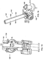
- Figures 16-22 illustrate another embodiment of the present hinged shield assembly 150.
- the shield assembly 150 includes a base 152 including a base flange 154 and a button assembly 156 secured to an edge of the flange 154 via a hinge 158.
- the base flange 154 is substantially planar, and is integrally formed with a needle hub 160 that passes through an approximate center of the flange 154.
- the needle hub 160, base flange 154, hinge 158 and portions of the button assembly 156 may be integrally formed, as by injection molding for example.
- the hinge 158 may comprise, as in the illustrated embodiment, a "living" hinge 158.
- the hinge 158 whether living or not, may be biased toward the exposed needle position as explained in further detail below.
- the button assembly 156 comprises a housing 162 and a button 164.
- the button 164 comprises an elongate stem or rod 166 and a head 168 at a first end of the stem 166.
- a passageway 170 within the housing 162 receives the stem 166 with the head 168 of the button 164 exposed and located at the side of the housing 162.
- the stem 166 includes an annular detent 172 that engages a groove 174 in the passageway 170 to resist relative movement of the button 164 and the housing 162.
- the detent 172 may not be annular.
- the detent 172 may comprise one or more semispherical protrusions from the stem 166 that engage correspondingly shaped recesses in the passageway 170.
- An operator applies digital pressure to the button 164 to overcome a threshold force and dislodge the detent 172 from the groove 174.
- Elastic deformation of the material from which the detent 172 and/or the housing 162 is constructed allows the button 164 to move from the initial position of Figure 20 to the depressed position of Figure 22 .
- the detent 172 exits the passageway 170 on the far side at which point the detent 172 housing 162 material returns to its initial shape.
- the detent 172 then engages the edge 176 of the passageway 170 at the far side so that the button 164 remains in the depressed position.
- the housing 162 includes a button receiving cavity 178 in which the button head 168 is located when it is in the depressed position to prevent unwanted manipulation of the button, such as to reset the button.
- the stem 166 extends across the needle 34 ( Figure 22 ) and prevents the needle 34 from being exposed, as explained in further detail below.
- the shield assembly 150 further comprises a shield 180 extending from the button assembly 156 in a direction away from the base flange 154.
- the shield 180 includes a first or outer shield 182 that at least partially surrounds and encloses a second or inner shield 184.
- the first and second shields 182, 184 are shaped as elongate, hollow, circular cylinders, and each includes a sidewall 186, 188 having a longitudinal channel 190, 192.
- the first and second shields 182, 184 are rotatable relative to one another, but are not translatable.
- a proximal end 194 of the first shield 182 includes a flange 196 that an operator may grip in order to apply a rotating force to the first shield 182.
- the shield assembly 150 of Figures 16-22 includes a ready-to-use position (not shown) in which the shield 180 covers the needle 34 and the channels 190, 192 on the first and second shields 182, 184 are not aligned.
- a ready-to-use position (not shown) in which the shield 180 covers the needle 34 and the channels 190, 192 on the first and second shields 182, 184 are not aligned.
- an operator rotates the first shield 182 with respect to the second shield 184 so that the two channels 190, 192 are aligned with one another (the open position).
- the shield 180 may be pivoted about the hinge 158 to the exposed needle position shown in Figures 16-18 .
- the hinge 158 may be biased toward the exposed needle position, or the operator may manually pivot the shield 180 with digital pressure.
- the tab 200 is also configured to abut a shoulder 202 of the housing 162 for delimiting the extent of rotation of the first shield.
- the tab 200 is configured to abut a shoulder 202 of the housing 162 to limit rotation in one direction and a part or edge 204 of the annular wall to limit rotation in the other direction.
- the operator pivots the shield 180 back to the open position. In this open position the operator then depresses the button 164 and so secures the shield 180 about the needle 34.
- the button 164 when the button 164 is depressed the stem 166 extends across the needle 34 on the side of the needle 34 opposite the hinge 158. Thus, the stem 166 forms a barrier that prevents anything but minimal pivoting of the shield 180.
- the tab 200 could be such that it delimits rotational movement of the shields by abutting the shoulder 202 and the edge 204 but does not abut and hinder the button 164 from being depressed in which case the operator can rotate the first shield 182 relative to the second shield 184 to again reach the ready-to-use position in which the needle is fully covered before depressing the button to secure the shield.
- the advantage of this alternative embodiment over and above the embodiment shown is that the needle is completely covered in the secured position as is also the case with the embodiments shown in Figs. 1-15 .
- the embodiment shown is however preferable as a tab which prevents the button from being depressed unintentionally in the packaged or ready-to-use position is of greater practical importance.
Landscapes
- Health & Medical Sciences (AREA)
- Engineering & Computer Science (AREA)
- Heart & Thoracic Surgery (AREA)
- Vascular Medicine (AREA)
- Anesthesiology (AREA)
- Biomedical Technology (AREA)
- Environmental & Geological Engineering (AREA)
- Hematology (AREA)
- Life Sciences & Earth Sciences (AREA)
- Animal Behavior & Ethology (AREA)
- General Health & Medical Sciences (AREA)
- Public Health (AREA)
- Veterinary Medicine (AREA)
- Infusion, Injection, And Reservoir Apparatuses (AREA)
Description
- The present invention relates generally to caps for needle devices, and more particularly to hinged cap devices for use with hypodermic needles.
- Recapping is a common procedure for periods between drawing up fluids into a syringe and administering injections through a needle. The recapping procedure can occasionally cause needlesticks since users sometime misalign the needles with the openings on the caps. Needlesticks can be painful, but can also cause great inconvenience because all needlesticks must be reported. Also, since needles related to needlesticks must be discarded, medications contained within the syringes are unnecessarily wasted. Furthermore, fluids linked to these "clean" type of needlesticks can cause injuries and adverse reactions.
-
US 5 632 732 A relates to a shielded needle assembly having an elongate shield with a proximal end, a distal end and a sidewall with an elongate opening. The shield is operable between an open position, where the distal point of the needle is exposed for use by passage through the elongate opening; a closed position, where the shield substantially obstructs access to the needle; and a latched position, where the shield is closed and the elongate opening is substantially obstructed as well as being the shield being substantially prevented from inadvertent movement to the open position. -
US 6 413 243 B1 discloses an apparatus for covering a used hypodermic syringe needle comprising a base, a pair of covers mounted moveably to the base, and at least one latching member mounted to the base. The covers can be moved into a closed position over the needle. - The preferred embodiments of the present hinged shield assembly and related methods have several features, no single one of which is solely responsible for their desirable attributes. Without limiting the scope of the present embodiments as expressed by the claims that follow, their more prominent features now will be discussed briefly. After considering this discussion, and particularly after reading the section entitled "Detailed Description of the Preferred Embodiments," one will understand how the features of the present embodiments provide advantages, which include the ability to lock the shield against further movement so that the needle contained within the shield cannot accidentally be re-exposed.
- One embodiment of the present methods of shielding a needle to prevent needlesticks comprises rotating a first shield in a first direction with respect to a second shield. The method further comprises pivoting the first and second shields in a first direction with respect to the needle to expose a sharp distal tip of the needle. The method further comprises pivoting the first and second shields in a second direction with respect to the needle, opposite the first direction, until the needle is at least partially enclosed within the first and second shields. The method further comprises rotating the first shield in a second direction, opposite the first direction, with respect to the second shield. The method further comprises translating the first shield with respect to the second shield to lock the second shield against further rotational and translational motion with respect to the first shield.
- One embodiment of the present hinged shield assembly is configured to shield a needle to prevent needlesticks. The assembly comprises a base including a hinge, a first shield and a second shield. The first shield extends from the base and at least partially surrounds the second shield. The first and second shields are configured to pivot about the hinge, and a distal end of the first shield is open.
- Another embodiment of the present hinged shield assembly is configured to shield a needle to prevent needlesticks. The assembly comprises a base including a hinge, a first shield and a second shield. The first shield extends from the base and at least partially surrounds the second shield. The first shield includes a sidewall and a channel extending along the sidewall in a direction parallel to a longitudinal axis of the first shield. The second shield includes a sidewall and a channel extending along the sidewall in a direction parallel to a longitudinal axis of the second shield. The first and second shields are configured to pivot about the hinge, and the first and second shields are rotatable with respect to one another such that the channels in each may be aligned.
- Another embodiment of the present hinged shield assembly is configured to shield a needle to prevent needlesticks. The assembly comprises a base including first and second spaced flanges and a hinge. The assembly further comprises a first shield and a second shield. The first shield extends from the base and at least partially surrounds the second shield. The first and second shields are configured to pivot about the hinge, and the second shield includes a tab that is selectively disposable within a space defined between the first and second flanges.
- Another embodiment of the present hinged shield assembly is configured to shield a needle to prevent needlesticks. The assembly comprises a base including first and second spaced flanges and a hinge. The assembly further comprises a first shield and a second shield. The first shield extends from the base and at least partially surrounds the second shield. The first and second shields are configured to pivot about the hinge, and the second shield includes a tab that is selectively disposable within a channel that extends along a sidewall of the first shield in a direction parallel to a longitudinal axis of the first shield.
- Another embodiment of the present hinged shield assembly is configured to shield a needle to prevent needlesticks. The assembly comprises a base including first and second spaced flanges and a hinge. The assembly further comprises a first shield and a second shield. The first shield extends from the base and at least partially surrounds the second shield. The first and second shields are configured to pivot about the hinge, and the first and second shields are translatable and rotatable with respect to one another.
- The preferred embodiments of the present hinged shield assembly and related methods now will be discussed in detail with an emphasis on highlighting the advantageous features. These embodiments depict the novel and non-obvious hinged shield assembly shown in the accompanying drawings, which are for illustrative purposes only. These drawings include the following figures, in which like numerals indicate like parts:
-
Figure 1 is a front perspective view of one embodiment of the present hinged shield assembly; -
Figure 2 is a partially exploded front perspective view of the hinged shield assembly ofFigure 1 ; -
Figure 3 is a detail front perspective view of a shield of the hinged shield assembly ofFigure 1 , showing the shield in an open position; -
Figure 4 is a detail front perspective view of a shield of the hinged shield assembly ofFigure 1 , showing the shield in an exposed needle position; -
Figure 5 is a detail front perspective view of a shield of the hinged shield assembly ofFigure 1 , showing the shield in a ready-to-use position; -
Figure 6 is a detail lower front perspective view of a shield of the hinged shield assembly ofFigure 1 , showing a position of a tab of the shield in the ready-to-use position; -
Figure 7 is a detail front perspective view of a shield of the hinged shield assembly ofFigure 1 , showing the shield in a secured position; -
Figure 8 is a detail lower front perspective view of a shield of the hinged shield assembly ofFigure 1 , showing a position of a tab of the shield in the secured position; -
Figure 9 is a detail front cross-sectional view of the base and proximal portions of the first and second shields of the hinged shield assembly ofFigure 1 , taken through the line 9-9 inFigure 5 ; -
Figure 10 is a detail front cross-sectional view of the base and proximal portions of the first and second shields of the hinged shield assembly ofFigure 1 , taken through the line 11-11 inFigure 7 ; -
Figure 11 is a detail view of the area ofFigure 10 contained within the circle 11-11; -
Figure 12 is a front perspective view of another embodiment of the present hinged shield assembly; -
Figure 13 is a front perspective view of another embodiment of the present hinged shield assembly, showing the shield in a ready-to-use position; -
Figure 14 is a front perspective view of another embodiment of the present hinged shield assembly, showing the shield in an open position; -
Figure 15 is a front perspective view of another embodiment of the present hinged shield assembly, showing the shield in a secured position; -
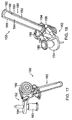
Figure 16 is a front perspective view of another embodiment of the present hinged shield assembly, showing the shield in an exposed needle position; -
Figure 17 is a front perspective view of the hinged shield assembly ofFigure 16 ; -
Figure 18 is a rear perspective view of the hinged shield assembly ofFigure 16 ; -
Figure 19 is a front detail perspective view of the hinged shield assembly ofFigure 16 , showing the shield in a ready-to-use position; -
Figure 20 is a top cross-sectional view of the hinged shield assembly ofFigure 16 , taken through the line 20-20 inFigure 19 ; -
Figure 21 is a left-side elevation detail view of the hinged shield assembly ofFigure 16 , showing the shield in a secured position; and -
Figure 22 is a top cross-sectional view of the hinged shield assembly ofFigure 16 , taken through the line 22-22 inFigure 21 . - The following detailed description describes the present embodiments with reference to the drawings. In the drawings, reference numbers label elements of the present embodiments. These reference numbers are reproduced below in connection with the discussion of the corresponding drawing features.
-
Figures 1-8 illustrate one embodiment of the present hingedshield assembly 30. The hingedshield assembly 30 cooperates with a syringe 32 (Figures 1 and 2 ) to selectively shield 42 a needle 34 (Figure 4 ) extending from aneedle hub 36, which engages adistal end 38 of thesyringe 32. With reference toFigure 1 , theshield assembly 30 comprises abase 40 and ashield 42 that is pivotable about thebase 40. As described in further detail below, theshield 42 is configured to be converted from a packaged or ready-to-use position (Figures 5 and 6 ) to an open position (Figure 3 ), and from the open position back to the ready-to-use position and then to a secured position (Figures 7 and 8 ). The ready-to-use position may also be viewed as a temporary lock position because while it prevents theshield 42 from being rotated away from the needle, it can be switched to an open position to permit administration or aspiration of medication. However, a practitioner may leave the needle exposed after filling the syringe and before injecting a patient without moving back to the ready-to-use position. - With reference to
Figures 3 and6 , thebase 40 comprises first and second spacedflanges first flange 44 extends from theneedle hub 36 in a direction substantially perpendicular to a longitudinal axis of theneedle 34. Thesecond flange 46 is substantially parallel to thefirst flange 44, and spaced from thefirst flange 44 in the distal direction (toward a sharpdistal tip 48 of the needle 34 (Figure 4 )). Awall section 50 connects the first andsecond flanges wall section 50 and thefirst flange 44 comprises ahinge 52. Theshield assembly 30 is pivotable about thehinge 52 between the open position (Figure 3 ) and an exposed needle position (Figure 4 ), as described in further detail below. - In certain embodiments the
shield assembly 30 may be made by injection molding. In such embodiments thebase 40 may comprise a single piece, and thehinge 52 may comprise a relatively thin portion of injection-molded plastic, commonly referred to as a "living" hinge. In such embodiments theshield assembly 30 further may be integrally formed as a single unit with theneedle hub 36. In other embodiments theshield assembly 30 may be formed separately and secured to theneedle hub 36 by known methods, such as welding or mechanical engagement to convert a simple commercially available hypodermic needle into a safety needle assembly. - With reference to
Figure 3 , theshield 42 extends from thesecond flange 46 in a direction away from thefirst flange 44. With reference toFigures 2 and3 , theshield 42 comprises a first orouter shield 54 and a second orinner shield 56. The first andsecond shields second shield 56 is rotatable with respect to thefirst shield 54 from the ready-to-use position ofFigure 5 to the open position ofFigure 3 . Thesecond shield 56 is further translatable with respect to thefirst shield 54 from the ready-to-use position ofFigure 5 to the secured position ofFigure 7 . - With reference to
Figure 2 , thefirst shield 54 is shaped substantially as an elongate, hollow, circular cylinder including asidewall 58. Thesidewall 58 includes achannel 60 that, in the illustrated embodiment, extends in the longitudinal direction from theproximal end 62 to thedistal end 64. Thedistal end 64 of thefirst shield 54 is open. Thefirst shield 54 further includes apush tab 66 extending from thesidewall 58 opposite thechannel 60. Thepush tab 66 provides a convenient surface for an operator to apply digital pressure to pivot theshield 42 between the open position (Figure 3 ) and the exposed needle position (Figure 4 ). - With reference to
Figures 2 and3 , thesecond shield 56 is shaped substantially as an elongate, hollow, circular cylinder including asidewall 68. Thesidewall 68 includes a channel 70 (Figure 3 ) that, in the illustrated embodiment, extends in the longitudinal direction from theproximal end 72 to thedistal end 74. Thedistal end 74 of thesecond shield 56 is closed, which is preferred although an open end may also be used. Thesecond shield 56 as shown is of the same length as thefirst shield 54 in that the distal ends of the two shields are generally level or flush. However in an alternative not illustrated embodiment, thesecond shield 56 can be longer than thefirst shield 54 so that thedistal end 74 of thesecond shield 56 protrudes out from thedistal end 64 of thefirst shield 54 in the ready-to-use and open positions and is then at least level with thedistal end 64 of thefirst shield 54 in the secure position. This difference provides a caregiver or user with a visual feedback thus enabling the user to more easily determine whether theshield 42 is in the ready-to-use or the secure position. Thesecond shield 56 further includes atab 76 at theproximal end 62 that extends outward in a direction substantially perpendicular to a longitudinal axis of thesecond shield 56. In the illustrated embodiment, thetab 76 is spaced approximately ninety-degrees from thechannel 70 around the circumference of thesecond shield 56. However, as those of ordinary skill in the art will appreciate, thetab 76 may occupy substantially any position relative to thechannel 70. - With reference to
Figure 5 , thefirst shield 54 substantially surrounds thesecond shield 56. During manufacture, thesecond shield 56 is inserted into thefirst shield 54 through its open distal end 64 (Figure 2 ) and translated toward the base 40 until it reaches the ready-to-use position ofFigure 5 . In this position, theneedle 34 is protected because thesidewall 68 of thesecond shield 56 interferes with theneedle 34 if theshield 42 is pivoted about the hinge 52 (Figure 6 ). Said differently, thesidewall 68 of the inner shield blocks thechannel 60 of the outer shield thus obstructing the path needed to pivot theshield 42 away from the needle. In certain embodiments, thesyringe 32 andshield assembly 30 may be transported from the manufacturer to the customer in the ready-to-use position. - With reference to
Figures 5-8 , thetab 76 provides a convenient surface upon which to apply digital pressure to translate thesecond shield 56 relative to thefirst shield 54. ComparingFigures 5 and7 , digital pressure applied to thetab 76 in the direction of thearrow 78 translates thesecond shield 56 relative to thefirst shield 54 from the ready-to-use position ofFigure 5 to the secured position ofFigure 7 . In the secured position the first andsecond shields Figure 6 , theproximal end 72 of thesecond shield 56 includes a diametricallyopposed slot 80 that cooperates with arib 82 on theneedle hub 36 to enable thesecond shield 56 to translate proximally relative to thefirst shield 54. When thesecond shield 56 is rotated away from the ready-to-use position ofFigures 5 and 6 , such as shown inFigures 3 and 4 , therib 82 form a barrier that prevents thesecond shield 56 from translating proximally relative to thefirst shield 54. However, when thesecond shield 56 is in the ready-to-use position theribs 82 align withslots 80 as shown inFigure 6 , and thesecond shield 56 is able to translate proximally relative to thefirst shield 54. Accordingly, aspects of the present invention include a provision for aligning sections of the first shield and the second shield for purposes of fixing the needle assembly in a secured position. -
Figures 9 and 10 show cross-sectional views of the proximal ends 62, 72 of the first andsecond shields Figure 9 ) and the secured position (Figure 10 ).Figure 11 shows an enlarged detail view ofFigure 10 . An inner edge at theproximal end 62 of thefirst shield 54 comprises adetent 84 that engages agroove 86 in thesecond shield 56. Aledge 88 at the proximal end of thegroove 86 engages thedetent 84 to resist translation of thesecond shield 56 in the distal direction relative to thefirst shield 54. Similarly, atapered surface 90 at the distal end of thegroove 86 engages thedetent 84 to resist translation of thesecond shield 56 in the proximal direction relative to thefirst shield 54. The taperedsurface 90, however, allows thesecond shield 56 to translate in the proximal direction relative to thefirst shield 54 when a threshold digital force is applied to thetab 76. Elastic deformation of the first andsecond shields second shield 56proximal portion 92 to slide through the relativelysmaller opening 94 at theproximal end 62 of thefirst shield 54. Adistal ledge 96 on thesecond shield 56 eventually passes thedetent 84, at which point the materials return to their original shape. In the secured position ofFigures 10 and11 thedistal ledge 96 on thesecond shield 56 engages thedetent 84 to resist any movement of thesecond shield 56 in the distal direction relative to thefirst shield 54. Theshields rib 82 andslot 80 prevents relative rotational motion. - To use the illustrated
needle shield assembly 30, an operator applies digital pressure to thetab 76 to rotate thesecond shield 56 in a first direction with respect to thefirst shield 54 from the ready-to-use position ofFigure 5 to the open position ofFigure 3 . In the open position thechannels shields shield 42 can freely pivot in a first direction from the open position to the exposed needle position ofFigure 4 . As theshield 42 pivots about thehinge 52, theneedle 34 passes through the alignedchannels shield 42 about thehinge 52 the operator may apply digital pressure to thepush tab 66. In certain embodiments, however, thehinge 52 may be biased toward the exposed needle position so that it springs to that position from the open position without the need to apply digital pressure. In this case apush tab 66 would not be necessary. The digital pressure applied to thetab 76 to rotate thesecond shield 56 to the open position can also be sufficient to further pivot the shield about the hinge which would also mean that there is no need for apush tab 66. When theshield 42 occupies the exposed needle position, the operator may use thesyringe 32 to inject fluid into a patient, or to withdraw fluid from a patient. - Upon completion of fluid injection/withdrawal, the operator pivots the
shield 42 back to the open position ofFigure 3 . To pivot theshield 42 about thehinge 52 the operator may apply digital pressure to thepush tab 66. Then, to secure theshield 42 about theneedle 34 he or she applies digital pressure to thetab 76 to rotate thesecond shield 56 back to the ready-to-use position ofFigure 5 . Finally, he or she applies digital pressure to thetab 76 in the direction of the arrow 78 (Figure 7 ) to translate thesecond shield 56 relative to thefirst shield 54 into the secured position (Figures 7 and 8 ). In the secured position the first andsecond shields needle 34 is thus safely contained within theshield 42 where it cannot accidentally prick anyone. -
Figure 12 illustrates another embodiment of the present hingedshield assembly 100. Theassembly 100 ofFigure 12 is similar to theassembly 30 ofFigures 1-11 , and includes anindicator 102 that provides a visual aid to the operation of theshield assembly 100. For example, the "Open"indicia 104 tells the operator that to move theshield 106 from the ready-to-use position to the open position he or she must push thetab 76 to rotate thesecond shield 56 in a first direction with respect to thefirst shield 108. The "Safe"indicia 110 tells the operator that to move theshield 42 from the ready-to-use position to the secure position he or she must push thetab 76 to translate thesecond shield 56 in the proximal direction with respect to thefirst shield 54. -
Figures 13-15 illustrate another embodiment of the present hingedshield assembly 120. Theassembly 120 ofFigures 13-15 is similar to theassembly 30 ofFigures 1-11 , except that thetab 76 is located more distally and somewhere between the distal end and the proximal end. With reference toFigure 13 , thetab 76 extends outward from thesidewall 122 of thesecond shield 124 at a location that is spaced from theproximal end 126 of thesecond shield 124. Thesidewall 128 of thefirst shield 130 includes achannel 132, from which abranch 134 that resembles a slot extends around a portion of the circumference of thefirst shield 130. Thebranch 134 is located at the same point along the first shield's length as thetab 76 is located along the second shield's length. Thesecond shield 124 can thus be rotated from the ready-to-use position (Figure 13 ) to the open position (Figure 14 ) by application of digital pressure to thetab 76, which causes thetab 76 to rotate into thebranch 134. Also, from the ready-to-use position thesecond shield 124 can be translated proximally relative to thefirst shield 130 by application of digital pressure to thetab 76, which moves theshield 136 into the secure position ofFigure 15 . In the illustrated embodiment, thebranch 134 is located adjacent thepush tab 66, and upper andlower fingers 138 of thepush tab 66 surround the branch 134 (Figure 14 ). In other embodiments, however, thebranch 134 may be located at a different position along the first shield's length relative to thepush tab 66 at all in which case the digital pressure applied totab 76 to rotate thesecond shield 124 to the open position is sufficient to further pivot the shield about the hinge. - As seen best in
Fig. 14 , the first flange 144 has a projecting rib located on its distal surface that runs in a direction substantially perpendicular to the longitudinal axis of the needle and thewall section 150 that connects the two flanges has a projecting rib which runs in a direction substantially parallel to the longitudinal axis of the needle. Both ribs interact with each other when in the ready-to-use and the secure position to prevent over-rotation of the caps relative to the needle to thereby damage, bend, or distort the needle. Thus, in accordance with aspects of the present invention, ribs are incorporated at the living hinge to prevent the needle from being contacted and deformed by the shields in the event a user applies too much pressure in both of these positions. In other embodiments, other limiting features are used to limit over-rotation. For example, a feature may be incorporated to abut the needle holder to prevent over-rotation. -
Figures 16-22 illustrate another embodiment of the present hingedshield assembly 150. With reference toFigures 16-18 , theshield assembly 150 includes a base 152 including abase flange 154 and abutton assembly 156 secured to an edge of theflange 154 via ahinge 158. Thebase flange 154 is substantially planar, and is integrally formed with aneedle hub 160 that passes through an approximate center of theflange 154. In certain embodiments, theneedle hub 160,base flange 154, hinge 158 and portions of thebutton assembly 156 may be integrally formed, as by injection molding for example. In such embodiments, thehinge 158 may comprise, as in the illustrated embodiment, a "living"hinge 158. In certain embodiments, thehinge 158, whether living or not, may be biased toward the exposed needle position as explained in further detail below. - With reference to
Figures 19 and 20 , thebutton assembly 156 comprises ahousing 162 and abutton 164. Thebutton 164 comprises an elongate stem orrod 166 and ahead 168 at a first end of thestem 166. Apassageway 170 within thehousing 162 receives thestem 166 with thehead 168 of thebutton 164 exposed and located at the side of thehousing 162. Thestem 166 includes anannular detent 172 that engages agroove 174 in thepassageway 170 to resist relative movement of thebutton 164 and thehousing 162. In other embodiments, thedetent 172 may not be annular. For example, thedetent 172 may comprise one or more semispherical protrusions from thestem 166 that engage correspondingly shaped recesses in thepassageway 170. - An operator applies digital pressure to the
button 164 to overcome a threshold force and dislodge thedetent 172 from thegroove 174. Elastic deformation of the material from which thedetent 172 and/or thehousing 162 is constructed allows thebutton 164 to move from the initial position ofFigure 20 to the depressed position ofFigure 22 . When thebutton 164 is fully depressed, thedetent 172 exits thepassageway 170 on the far side at which point thedetent 172housing 162 material returns to its initial shape. Thedetent 172 then engages the edge 176 of thepassageway 170 at the far side so that thebutton 164 remains in the depressed position. Thehousing 162 includes abutton receiving cavity 178 in which thebutton head 168 is located when it is in the depressed position to prevent unwanted manipulation of the button, such as to reset the button. In this position, thestem 166 extends across the needle 34 (Figure 22 ) and prevents theneedle 34 from being exposed, as explained in further detail below. - With reference to
Figure 18 , theshield assembly 150 further comprises ashield 180 extending from thebutton assembly 156 in a direction away from thebase flange 154. Similarly to the embodiments described above, theshield 180 includes a first orouter shield 182 that at least partially surrounds and encloses a second orinner shield 184. The first andsecond shields sidewall longitudinal channel second shields proximal end 194 of thefirst shield 182 includes aflange 196 that an operator may grip in order to apply a rotating force to thefirst shield 182. - Like the embodiments of the present hinged shield assembly described above and shown in
Figures 1-15 , theshield assembly 150 ofFigures 16-22 includes a ready-to-use position (not shown) in which theshield 180 covers theneedle 34 and thechannels second shields shield assembly 150 ofFigures 16-22 , an operator rotates thefirst shield 182 with respect to thesecond shield 184 so that the twochannels shield 180 may be pivoted about thehinge 158 to the exposed needle position shown inFigures 16-18 . Again, thehinge 158 may be biased toward the exposed needle position, or the operator may manually pivot theshield 180 with digital pressure. Atab 200 extending axially at the proximal end of thefirst shield 182, proximally of theflange 196, is incorporated to abut thebutton 164 in the packaged and the ready-to-use position to prevent thebutton 164 from being depressed unintentionally in these positions. Thetab 200 is also configured to abut ashoulder 202 of thehousing 162 for delimiting the extent of rotation of the first shield. Thetab 200 is configured to abut ashoulder 202 of thehousing 162 to limit rotation in one direction and a part or edge 204 of the annular wall to limit rotation in the other direction. - After injecting or withdrawing fluids through the
needle 34, the operator pivots theshield 180 back to the open position. In this open position the operator then depresses thebutton 164 and so secures theshield 180 about theneedle 34. With reference toFigure 22 , when thebutton 164 is depressed thestem 166 extends across theneedle 34 on the side of theneedle 34 opposite thehinge 158. Thus, thestem 166 forms a barrier that prevents anything but minimal pivoting of theshield 180. In an alternative embodiment, not shown, thetab 200 could be such that it delimits rotational movement of the shields by abutting theshoulder 202 and theedge 204 but does not abut and hinder thebutton 164 from being depressed in which case the operator can rotate thefirst shield 182 relative to thesecond shield 184 to again reach the ready-to-use position in which the needle is fully covered before depressing the button to secure the shield. The advantage of this alternative embodiment over and above the embodiment shown is that the needle is completely covered in the secured position as is also the case with the embodiments shown inFigs. 1-15 . The embodiment shown is however preferable as a tab which prevents the button from being depressed unintentionally in the packaged or ready-to-use position is of greater practical importance. - The above description presents the best mode contemplated for carrying out the present hinged shield assembly and related methods, and of the manner and process of making and using it, in such full, clear, concise, and exact terms as to enable any person skilled in the art to which it pertains to make and use this hinged shield assembly. This hinged shield assembly is, however, susceptible to modifications and alternate constructions from that discussed above that are fully equivalent. For example, the needle may be left exposed after filling the syringe and before injecting the patient without having to move to a ready-to-use position. Additionally, features and aspects discussed for one embodiment may be interchanged and use with another embodiment provided there is no conflict. Consequently, this hinged shield assembly is not limited to the particular embodiments disclosed. On the contrary, this hinged shield assembly covers all modifications and alternate constructions coming within the scope of the hinged shield assembly as generally expressed by the following claims, which particularly point out and distinctly claim the subject matter of the hinged shield assembly.
Claims (11)
- A hinged shield assembly (30) configured to receive and shield a needle in a secured position to prevent needlesticks, the assembly comprising:a hub (36) having a needle (48) attached thereto and including a hinge (52),a first shield (54) and a second shield (56) both configured to pivot about the hinge in an open position when the needle is exposed,the first shield (54) including a sidewall (58) and a channel (60) extending along the sidewall in a direction parallel to a longitudinal axis of the first shield,the second shield (56) including a sidewall (68) and a channel (70) extending along the sidewall in a direction parallel to a longitudinal axis of the second shield, wherein the first shield (54) extends from the hub and has an open distal end (64) and at least partially surrounds the second shield (56),characterized in thatthe first and second shields are translatable with respect to one another.
- The hinged shield assembly of any one of the preceding claims, wherein the first and second shields are rotatable with respect to one another such that the channels in each may be aligned.
- The hinged shield assembly of claim 2, wherein relative translation of the first and second shields (54, 56) locks the second shield against further rotational and translational motion with respect to the first shield in the secured position.
- The hinged shield assembly of any one of the preceding claims, wherein the proximal end (72) of the second shield (56) includes a slot (80) which cooperates with a rib (82) on the hub (36) in the secured position.
- The hinged shield assembly of any one of the preceding claims, wherein the first shield includes a push tab (66) extending from the sidewall (58) for the application of digital pressure to pivot the first and second shields (54, 56) relative to the needle.
- The hinged shield assembly of any one of the preceding claims, wherein the second shield (56) is longer than the first shield (54) and protrudes out from the distal end (64) of the first shield (54) in the open position.
- The hinged shield assembly of any one of the preceding claims wherein the sidewall (68) of the second shield (56) includes a tab (76) which extends outward in a direction substantially perpendicular to a longitudinal axis of the second shield (56).
- The hinged shield assembly of any one of the preceding claims wherein the hub (36) includes first and second spaced flanges (44, 46).
- The hinged shield assembly of claim 7, wherein the tab (76) of the second shield (56) is selectively disposable within a space defined between the first and second flanges (44, 46) of the hub (36) so that the first and the second shields (54, 56) are pivotable relative to the needle (48) on relative rotation of the first and second shields (54, 56) in a first direction with respect to the first shield (54) and the first and second shields (54, 56) are translatable with respect to one another under digital pressure applied to the tab (76) of the second shield (56) on relative rotation of the first and second shields (54, 56) in a second direction with respect to the first shield (54).
- The hinged shield assembly of claim 7, wherein a slot (134) branches off from the side wall (128) of the first shield (130) and the tab (76) of the second shield (124) is selectively disposable either in this slot so that the first and second shields (130, 124) are pivotable relative to the needle or in the channel (132) of the first shield (130) so that the first and second shields (130, 124) are translatable with respect to one another under digital pressure applied to the tab (76) of the second shield (124).
- A method of shielding a needle to prevent needlesticks with a hinged needle assembly of any of the preceding claims, the method comprising: rotating the second shield (56) in a first direction with respect to the first shield (54); pivoting the first and second shields (54, 56) in a first direction with respect to the needle (48) to expose the sharp distal tip of the needle; pivoting the first and second shields (54, 56) in a second direction with respect to the needle, opposite the first direction, until the needle is at least partially enclosed within the first and second shields (54, 56); rotating the second shield (56) in a second direction, opposite the first direction, with respect to the first shield (54); and translating the second shield (56) with respect to the first shield to lock both the first shield and the second shield (54, 56) against further rotational, pivotal and translational motion with respect to each other and to the needle.
Applications Claiming Priority (2)
| Application Number | Priority Date | Filing Date | Title |
|---|---|---|---|
| US11564708P | 2008-11-18 | 2008-11-18 | |
| PCT/US2009/064215 WO2010059502A2 (en) | 2008-11-18 | 2009-11-12 | Hinged shield assembly and related methods |
Publications (3)
| Publication Number | Publication Date |
|---|---|
| EP2355876A2 EP2355876A2 (en) | 2011-08-17 |
| EP2355876A4 EP2355876A4 (en) | 2013-01-09 |
| EP2355876B1 true EP2355876B1 (en) | 2016-01-27 |
Family
ID=42198750
Family Applications (1)
| Application Number | Title | Priority Date | Filing Date |
|---|---|---|---|
| EP09828048.0A Not-in-force EP2355876B1 (en) | 2008-11-18 | 2009-11-12 | Hinged shield assembly and related methods |
Country Status (3)
| Country | Link |
|---|---|
| US (1) | US9149584B2 (en) |
| EP (1) | EP2355876B1 (en) |
| WO (1) | WO2010059502A2 (en) |
Families Citing this family (9)
| Publication number | Priority date | Publication date | Assignee | Title |
|---|---|---|---|---|
| WO2009026530A1 (en) * | 2007-08-23 | 2009-02-26 | Cardious, Inc. | Conduit protector |
| CN103269740A (en) | 2010-11-22 | 2013-08-28 | B.布劳恩梅尔松根股份公司 | Hinged shield assemblies and related methods |
| EP2676693B1 (en) | 2011-02-14 | 2019-09-11 | Terumo Kabushiki Kaisha | Safety needle assembly |
| WO2013070789A2 (en) | 2011-11-07 | 2013-05-16 | Safety Syringes, Inc. | Contact trigger release needle guard |
| CN105943063B (en) * | 2012-03-08 | 2019-06-04 | 贝克顿·迪金森公司 | Blood collection assembly with multi-functional shield |
| US10029049B2 (en) | 2015-03-19 | 2018-07-24 | B. Braun Melsungen Ag | Hinged shield assemblies and related methods |
| WO2019149655A1 (en) * | 2018-01-31 | 2019-08-08 | Becton Dickinson France | Protection device for a needle |
| JP2022537671A (en) * | 2019-06-21 | 2022-08-29 | ベクトン ディキンソン フランス | Safety device to prevent needlestick injuries from medical injection device needles |
| DE102020126258A1 (en) | 2020-10-07 | 2022-04-07 | Stephan Fischer | Safety cover for coupling with an injection device |
Family Cites Families (11)
| Publication number | Priority date | Publication date | Assignee | Title |
|---|---|---|---|---|
| US5405332A (en) * | 1994-03-28 | 1995-04-11 | Opalek; A. Allen | Shield apparatus for syringe needle |
| US5599313A (en) * | 1995-02-03 | 1997-02-04 | Becton, Dickinson And Company | Needle shield assembly having safety indication features |
| US5632732A (en) * | 1996-09-11 | 1997-05-27 | Becton, Dickinson And Company | Needle assembly having single handedly activated shield |
| US6015397A (en) * | 1997-06-20 | 2000-01-18 | Elson; Edward E. | Needle point guard safety cap assembly |
| US6699217B2 (en) * | 1999-08-23 | 2004-03-02 | Becton, Dickinson And Company | Safety needle assembly |
| US6413243B1 (en) | 2000-02-21 | 2002-07-02 | Vital Signs, Inc. | Apparatus for covering a used syringe needle |
| JP4819256B2 (en) | 2001-08-10 | 2011-11-24 | テルモ株式会社 | Puncture tool |
| US6869418B2 (en) | 2001-08-17 | 2005-03-22 | Hypoguard Usa Inc. | Safety shield for a needle assembly |
| US7553296B2 (en) * | 2003-02-14 | 2009-06-30 | Tyco Healthcare Group Lp | Safety device with trigger mechanism |
| US8016796B2 (en) | 2005-05-27 | 2011-09-13 | Smiths Medical Asd, Inc. | Safety needle device with snap feature and method of making same |
| US20080269693A1 (en) * | 2007-04-26 | 2008-10-30 | Tyco Healthcare Group Lp | Multifunctional medical access device |
-
2009
- 2009-11-12 US US13/129,789 patent/US9149584B2/en not_active Expired - Fee Related
- 2009-11-12 WO PCT/US2009/064215 patent/WO2010059502A2/en active Application Filing
- 2009-11-12 EP EP09828048.0A patent/EP2355876B1/en not_active Not-in-force
Also Published As
| Publication number | Publication date |
|---|---|
| EP2355876A2 (en) | 2011-08-17 |
| US20110288496A1 (en) | 2011-11-24 |
| WO2010059502A2 (en) | 2010-05-27 |
| WO2010059502A3 (en) | 2010-09-23 |
| EP2355876A4 (en) | 2013-01-09 |
| US9149584B2 (en) | 2015-10-06 |
Similar Documents
| Publication | Publication Date | Title |
|---|---|---|
| EP2355876B1 (en) | Hinged shield assembly and related methods | |
| AU737080B2 (en) | Single-use safety syringe | |
| US5055102A (en) | Swing-away disposable syringe needle cover | |
| US6106500A (en) | Hypodermic needle assembly | |
| CN110072576B (en) | Safety needle device | |
| CN107261263B (en) | Syringe with a needle | |
| EP0761247B1 (en) | Needle shield assembly having a releasable lock | |
| JP5885102B2 (en) | Safety needle assembly and method | |
| CA2288461C (en) | Improved safety syringe | |
| EP3002020B1 (en) | Needle shield aasembly | |
| EP1557191B1 (en) | A safety needle assembly | |
| JPH10127767A (en) | Needle assembly provided with needle barrier which can be operated by one hand | |
| US5643222A (en) | Hypodermic needle assembly | |
| CA2168567A1 (en) | Disposable self-shielding aspirating syringe | |
| JP2008538298A (en) | Catheter introducer with needle protection | |
| EP1592346B1 (en) | Safety needle assembly | |
| WO1993001851A1 (en) | Skin puncturing instruments, especially clinical needles | |
| WO1997029798A1 (en) | Device | |
| US20220305214A1 (en) | Safety Device for Preventing Needle Stick Injury with a Needle of a Medical Injection Device | |
| CN115227914A (en) | Safety assembly | |
| US20230338668A1 (en) | Safety Device for Preventing Needle Stick Injury with a Needle of a Medical Injection Device | |
| JP2004242758A (en) | Medical catheter | |
| CN115916301A (en) | Safety device for a needle of a medical device |
Legal Events
| Date | Code | Title | Description |
|---|---|---|---|
| PUAI | Public reference made under article 153(3) epc to a published international application that has entered the european phase |
Free format text: ORIGINAL CODE: 0009012 |
|
| 17P | Request for examination filed |
Effective date: 20110614 |
|
| AK | Designated contracting states |
Kind code of ref document: A2 Designated state(s): AT BE BG CH CY CZ DE DK EE ES FI FR GB GR HR HU IE IS IT LI LT LU LV MC MK MT NL NO PL PT RO SE SI SK SM TR |
|
| DAX | Request for extension of the european patent (deleted) | ||
| A4 | Supplementary search report drawn up and despatched |
Effective date: 20121211 |
|
| RIC1 | Information provided on ipc code assigned before grant |
Ipc: A61M 5/32 20060101AFI20121205BHEP Ipc: A61M 5/34 20060101ALI20121205BHEP |
|
| GRAP | Despatch of communication of intention to grant a patent |
Free format text: ORIGINAL CODE: EPIDOSNIGR1 |
|
| INTG | Intention to grant announced |
Effective date: 20150701 |
|
| GRAR | Information related to intention to grant a patent recorded |
Free format text: ORIGINAL CODE: EPIDOSNIGR71 |
|
| GRAS | Grant fee paid |
Free format text: ORIGINAL CODE: EPIDOSNIGR3 |
|
| INTG | Intention to grant announced |
Effective date: 20151105 |
|
| GRAA | (expected) grant |
Free format text: ORIGINAL CODE: 0009210 |
|
| AK | Designated contracting states |
Kind code of ref document: B1 Designated state(s): AT BE BG CH CY CZ DE DK EE ES FI FR GB GR HR HU IE IS IT LI LT LU LV MC MK MT NL NO PL PT RO SE SI SK SM TR |
|
| REG | Reference to a national code |
Ref country code: GB Ref legal event code: FG4D |
|
| REG | Reference to a national code |
Ref country code: CH Ref legal event code: EP |
|
| REG | Reference to a national code |
Ref country code: AT Ref legal event code: REF Ref document number: 772398 Country of ref document: AT Kind code of ref document: T Effective date: 20160215 |
|
| REG | Reference to a national code |
Ref country code: IE Ref legal event code: FG4D |
|
| REG | Reference to a national code |
Ref country code: DE Ref legal event code: R096 Ref document number: 602009036103 Country of ref document: DE |
|
| REG | Reference to a national code |
Ref country code: LT Ref legal event code: MG4D |
|
| REG | Reference to a national code |
Ref country code: NL Ref legal event code: MP Effective date: 20160127 |
|
| REG | Reference to a national code |
Ref country code: AT Ref legal event code: MK05 Ref document number: 772398 Country of ref document: AT Kind code of ref document: T Effective date: 20160127 |
|
| PG25 | Lapsed in a contracting state [announced via postgrant information from national office to epo] |
Ref country code: NL Free format text: LAPSE BECAUSE OF FAILURE TO SUBMIT A TRANSLATION OF THE DESCRIPTION OR TO PAY THE FEE WITHIN THE PRESCRIBED TIME-LIMIT Effective date: 20160127 |
|
| PG25 | Lapsed in a contracting state [announced via postgrant information from national office to epo] |
Ref country code: FI Free format text: LAPSE BECAUSE OF FAILURE TO SUBMIT A TRANSLATION OF THE DESCRIPTION OR TO PAY THE FEE WITHIN THE PRESCRIBED TIME-LIMIT Effective date: 20160127 Ref country code: GR Free format text: LAPSE BECAUSE OF FAILURE TO SUBMIT A TRANSLATION OF THE DESCRIPTION OR TO PAY THE FEE WITHIN THE PRESCRIBED TIME-LIMIT Effective date: 20160428 Ref country code: IT Free format text: LAPSE BECAUSE OF FAILURE TO SUBMIT A TRANSLATION OF THE DESCRIPTION OR TO PAY THE FEE WITHIN THE PRESCRIBED TIME-LIMIT Effective date: 20160127 Ref country code: ES Free format text: LAPSE BECAUSE OF FAILURE TO SUBMIT A TRANSLATION OF THE DESCRIPTION OR TO PAY THE FEE WITHIN THE PRESCRIBED TIME-LIMIT Effective date: 20160127 Ref country code: HR Free format text: LAPSE BECAUSE OF FAILURE TO SUBMIT A TRANSLATION OF THE DESCRIPTION OR TO PAY THE FEE WITHIN THE PRESCRIBED TIME-LIMIT Effective date: 20160127 Ref country code: NO Free format text: LAPSE BECAUSE OF FAILURE TO SUBMIT A TRANSLATION OF THE DESCRIPTION OR TO PAY THE FEE WITHIN THE PRESCRIBED TIME-LIMIT Effective date: 20160427 |
|
| PG25 | Lapsed in a contracting state [announced via postgrant information from national office to epo] |
Ref country code: AT Free format text: LAPSE BECAUSE OF FAILURE TO SUBMIT A TRANSLATION OF THE DESCRIPTION OR TO PAY THE FEE WITHIN THE PRESCRIBED TIME-LIMIT Effective date: 20160127 Ref country code: SE Free format text: LAPSE BECAUSE OF FAILURE TO SUBMIT A TRANSLATION OF THE DESCRIPTION OR TO PAY THE FEE WITHIN THE PRESCRIBED TIME-LIMIT Effective date: 20160127 Ref country code: PT Free format text: LAPSE BECAUSE OF FAILURE TO SUBMIT A TRANSLATION OF THE DESCRIPTION OR TO PAY THE FEE WITHIN THE PRESCRIBED TIME-LIMIT Effective date: 20160527 Ref country code: LV Free format text: LAPSE BECAUSE OF FAILURE TO SUBMIT A TRANSLATION OF THE DESCRIPTION OR TO PAY THE FEE WITHIN THE PRESCRIBED TIME-LIMIT Effective date: 20160127 Ref country code: PL Free format text: LAPSE BECAUSE OF FAILURE TO SUBMIT A TRANSLATION OF THE DESCRIPTION OR TO PAY THE FEE WITHIN THE PRESCRIBED TIME-LIMIT Effective date: 20160127 Ref country code: IS Free format text: LAPSE BECAUSE OF FAILURE TO SUBMIT A TRANSLATION OF THE DESCRIPTION OR TO PAY THE FEE WITHIN THE PRESCRIBED TIME-LIMIT Effective date: 20160527 Ref country code: LT Free format text: LAPSE BECAUSE OF FAILURE TO SUBMIT A TRANSLATION OF THE DESCRIPTION OR TO PAY THE FEE WITHIN THE PRESCRIBED TIME-LIMIT Effective date: 20160127 |
|
| REG | Reference to a national code |
Ref country code: DE Ref legal event code: R097 Ref document number: 602009036103 Country of ref document: DE |
|
| PG25 | Lapsed in a contracting state [announced via postgrant information from national office to epo] |
Ref country code: EE Free format text: LAPSE BECAUSE OF FAILURE TO SUBMIT A TRANSLATION OF THE DESCRIPTION OR TO PAY THE FEE WITHIN THE PRESCRIBED TIME-LIMIT Effective date: 20160127 Ref country code: DK Free format text: LAPSE BECAUSE OF FAILURE TO SUBMIT A TRANSLATION OF THE DESCRIPTION OR TO PAY THE FEE WITHIN THE PRESCRIBED TIME-LIMIT Effective date: 20160127 |
|
| REG | Reference to a national code |
Ref country code: FR Ref legal event code: PLFP Year of fee payment: 8 |
|
| PG25 | Lapsed in a contracting state [announced via postgrant information from national office to epo] |
Ref country code: RO Free format text: LAPSE BECAUSE OF FAILURE TO SUBMIT A TRANSLATION OF THE DESCRIPTION OR TO PAY THE FEE WITHIN THE PRESCRIBED TIME-LIMIT Effective date: 20160127 Ref country code: SM Free format text: LAPSE BECAUSE OF FAILURE TO SUBMIT A TRANSLATION OF THE DESCRIPTION OR TO PAY THE FEE WITHIN THE PRESCRIBED TIME-LIMIT Effective date: 20160127 Ref country code: CZ Free format text: LAPSE BECAUSE OF FAILURE TO SUBMIT A TRANSLATION OF THE DESCRIPTION OR TO PAY THE FEE WITHIN THE PRESCRIBED TIME-LIMIT Effective date: 20160127 Ref country code: SK Free format text: LAPSE BECAUSE OF FAILURE TO SUBMIT A TRANSLATION OF THE DESCRIPTION OR TO PAY THE FEE WITHIN THE PRESCRIBED TIME-LIMIT Effective date: 20160127 |
|
| PLBE | No opposition filed within time limit |
Free format text: ORIGINAL CODE: 0009261 |
|
| STAA | Information on the status of an ep patent application or granted ep patent |
Free format text: STATUS: NO OPPOSITION FILED WITHIN TIME LIMIT |
|
| PG25 | Lapsed in a contracting state [announced via postgrant information from national office to epo] |
Ref country code: BE Free format text: LAPSE BECAUSE OF FAILURE TO SUBMIT A TRANSLATION OF THE DESCRIPTION OR TO PAY THE FEE WITHIN THE PRESCRIBED TIME-LIMIT Effective date: 20160127 |
|
| 26N | No opposition filed |
Effective date: 20161028 |
|
| PG25 | Lapsed in a contracting state [announced via postgrant information from national office to epo] |
Ref country code: BG Free format text: LAPSE BECAUSE OF FAILURE TO SUBMIT A TRANSLATION OF THE DESCRIPTION OR TO PAY THE FEE WITHIN THE PRESCRIBED TIME-LIMIT Effective date: 20160427 Ref country code: SI Free format text: LAPSE BECAUSE OF FAILURE TO SUBMIT A TRANSLATION OF THE DESCRIPTION OR TO PAY THE FEE WITHIN THE PRESCRIBED TIME-LIMIT Effective date: 20160127 |
|
| REG | Reference to a national code |
Ref country code: CH Ref legal event code: PL |
|
| PG25 | Lapsed in a contracting state [announced via postgrant information from national office to epo] |
Ref country code: CH Free format text: LAPSE BECAUSE OF NON-PAYMENT OF DUE FEES Effective date: 20161130 Ref country code: LI Free format text: LAPSE BECAUSE OF NON-PAYMENT OF DUE FEES Effective date: 20161130 |
|
| REG | Reference to a national code |
Ref country code: IE Ref legal event code: MM4A |
|
| PG25 | Lapsed in a contracting state [announced via postgrant information from national office to epo] |
Ref country code: LU Free format text: LAPSE BECAUSE OF NON-PAYMENT OF DUE FEES Effective date: 20161130 |
|
| REG | Reference to a national code |
Ref country code: FR Ref legal event code: PLFP Year of fee payment: 9 |
|
| PG25 | Lapsed in a contracting state [announced via postgrant information from national office to epo] |
Ref country code: IE Free format text: LAPSE BECAUSE OF NON-PAYMENT OF DUE FEES Effective date: 20161112 |
|
| PGFP | Annual fee paid to national office [announced via postgrant information from national office to epo] |
Ref country code: DE Payment date: 20171124 Year of fee payment: 9 Ref country code: FR Payment date: 20171124 Year of fee payment: 9 |
|
| PGFP | Annual fee paid to national office [announced via postgrant information from national office to epo] |
Ref country code: GB Payment date: 20171124 Year of fee payment: 9 |
|
| PG25 | Lapsed in a contracting state [announced via postgrant information from national office to epo] |
Ref country code: HU Free format text: LAPSE BECAUSE OF FAILURE TO SUBMIT A TRANSLATION OF THE DESCRIPTION OR TO PAY THE FEE WITHIN THE PRESCRIBED TIME-LIMIT; INVALID AB INITIO Effective date: 20091112 Ref country code: CY Free format text: LAPSE BECAUSE OF FAILURE TO SUBMIT A TRANSLATION OF THE DESCRIPTION OR TO PAY THE FEE WITHIN THE PRESCRIBED TIME-LIMIT Effective date: 20160127 |
|
| PG25 | Lapsed in a contracting state [announced via postgrant information from national office to epo] |
Ref country code: MK Free format text: LAPSE BECAUSE OF FAILURE TO SUBMIT A TRANSLATION OF THE DESCRIPTION OR TO PAY THE FEE WITHIN THE PRESCRIBED TIME-LIMIT Effective date: 20160127 Ref country code: TR Free format text: LAPSE BECAUSE OF FAILURE TO SUBMIT A TRANSLATION OF THE DESCRIPTION OR TO PAY THE FEE WITHIN THE PRESCRIBED TIME-LIMIT Effective date: 20160127 Ref country code: MC Free format text: LAPSE BECAUSE OF FAILURE TO SUBMIT A TRANSLATION OF THE DESCRIPTION OR TO PAY THE FEE WITHIN THE PRESCRIBED TIME-LIMIT Effective date: 20160127 |
|
| PG25 | Lapsed in a contracting state [announced via postgrant information from national office to epo] |
Ref country code: MT Free format text: LAPSE BECAUSE OF NON-PAYMENT OF DUE FEES Effective date: 20161112 |
|
| REG | Reference to a national code |
Ref country code: DE Ref legal event code: R119 Ref document number: 602009036103 Country of ref document: DE |
|
| GBPC | Gb: european patent ceased through non-payment of renewal fee |
Effective date: 20181112 |
|
| PG25 | Lapsed in a contracting state [announced via postgrant information from national office to epo] |
Ref country code: DE Free format text: LAPSE BECAUSE OF NON-PAYMENT OF DUE FEES Effective date: 20190601 Ref country code: FR Free format text: LAPSE BECAUSE OF NON-PAYMENT OF DUE FEES Effective date: 20181130 |
|
| PG25 | Lapsed in a contracting state [announced via postgrant information from national office to epo] |
Ref country code: GB Free format text: LAPSE BECAUSE OF NON-PAYMENT OF DUE FEES Effective date: 20181112 |