JP4478448B2 - Hinge needle shield assembly with needle cannula lock - Google Patents
Hinge needle shield assembly with needle cannula lock Download PDFInfo
- Publication number
- JP4478448B2 JP4478448B2 JP2003501518A JP2003501518A JP4478448B2 JP 4478448 B2 JP4478448 B2 JP 4478448B2 JP 2003501518 A JP2003501518 A JP 2003501518A JP 2003501518 A JP2003501518 A JP 2003501518A JP 4478448 B2 JP4478448 B2 JP 4478448B2
- Authority
- JP
- Japan
- Prior art keywords
- needle
- needle shield
- base
- lock assembly
- assembly
- Prior art date
- Legal status (The legal status is an assumption and is not a legal conclusion. Google has not performed a legal analysis and makes no representation as to the accuracy of the status listed.)
- Expired - Lifetime
Links
Images


Classifications
-
- A—HUMAN NECESSITIES
- A61—MEDICAL OR VETERINARY SCIENCE; HYGIENE
- A61M—DEVICES FOR INTRODUCING MEDIA INTO, OR ONTO, THE BODY; DEVICES FOR TRANSDUCING BODY MEDIA OR FOR TAKING MEDIA FROM THE BODY; DEVICES FOR PRODUCING OR ENDING SLEEP OR STUPOR
- A61M5/00—Devices for bringing media into the body in a subcutaneous, intra-vascular or intramuscular way; Accessories therefor, e.g. filling or cleaning devices, arm-rests
- A61M5/178—Syringes
- A61M5/31—Details
- A61M5/32—Needles; Details of needles pertaining to their connection with syringe or hub; Accessories for bringing the needle into, or holding the needle on, the body; Devices for protection of needles
- A61M5/3205—Apparatus for removing or disposing of used needles or syringes, e.g. containers; Means for protection against accidental injuries from used needles
- A61M5/321—Means for protection against accidental injuries by used needles
- A61M5/3216—Caps placed transversally onto the needle, e.g. pivotally attached to the needle base
Description
本発明の分野は皮下針などの医療装置における針シールド組み立て品および、そのような組み立て品を製造する方法に関する。 The field of the invention relates to needle shield assemblies in medical devices such as hypodermic needles and methods of manufacturing such assemblies.
皮下針を使用する上で不慮の針突き刺しによって、病気が伝染する可能性がある。したがって、様々な種類の針シールドが不慮の針突き刺しの可能性を低減するために設計されてきた。 Inadvertent needle sticks when using hypodermic needles can transmit the disease. Therefore, various types of needle shields have been designed to reduce the possibility of accidental needle sticks.
針の近くにヒンジがある針シールドは片手で針を再シールドできるという利点を有している。加えて、従来からのいくつかの針シールド組み立て品は、ヒンジのある針シールドを含んでいる。 A needle shield with a hinge near the needle has the advantage that the needle can be reshielded with one hand. In addition, some conventional needle shield assemblies include a hinged needle shield.
ヒンジのある針シールドを閉じた状態、すなわち針を保護する位置で固定するために、様々な手段が設けられてきた。針をシールドするとともにその後、針がシールドされない状態となるのを防止するために、針シールドを針と係合させるべく、屈折可能な部材が針シールド上に設けられてきた。そのような部材は、針シールドの中に針を閉じ込める。また、ロックは、針シールドと針支持構造体とのロック係合によって達成される。 Various means have been provided to secure the hinged needle shield in a closed state, i.e., in a protective position. In order to shield the needle and subsequently prevent the needle from becoming unshielded, a bendable member has been provided on the needle shield to engage the needle shield with the needle. Such members confine the needle within the needle shield. Locking is also achieved by lock engagement between the needle shield and the needle support structure.
本発明の針シールド組み立て品は、基端と末端を有する針ハブの末端に固定された針カニューレを含んでいる。ハブはシリンジなどの医療装置と接続するための基端を有するものが提供されていてもよい。針シールドベースは針ハブと回転可能に連結されている。1または複数のロック部材を有する別体のロック組み立て体が針カニューレを係合するために設けられている。このロック組み立て体は、1または複数のロック部材が針カニューレと固定的に係合可能であるように、針シールドの末端部分に連結されている。少なくとも一つの針シールドベースとロック組み立て体が針カニューレの少なくとも一部を収容するための空間(キャビティ)を有している。 The needle shield assembly of the present invention includes a needle cannula secured to the distal end of a needle hub having a proximal end and a distal end. The hub may be provided with a proximal end for connecting to a medical device such as a syringe. The needle shield base is rotatably connected to the needle hub. A separate locking assembly having one or more locking members is provided for engaging the needle cannula. The lock assembly is coupled to the distal portion of the needle shield such that one or more lock members are securely engageable with the needle cannula. At least one needle shield base and lock assembly has a space (cavity) for receiving at least a portion of the needle cannula.
本発明の第1実施形態において、針シールドベースは第1キャビティを有し、ロック組み立て体は第2キャビティを定めるキャップを有する。キャップは、第1および第2キャビティが隣接し、それらの1または複数のロック部材が針カニューレの軸と係合可能となるように、針シールドの一部に固定されている。 In a first embodiment of the invention, the needle shield base has a first cavity and the lock assembly has a cap that defines a second cavity. The cap is secured to a portion of the needle shield such that the first and second cavities are adjacent and their one or more locking members are engageable with the needle cannula shaft.
本発明の第2実施形態において、針シールドベースおよびロック組み立て体は、複数の位置で連結可能となるように、組み立てられている。針シールドに対してロック組み立て体の位置決めは、シールドが閉じた位置にあるときに、針カニューレと係合する位置にロック組み立て体のロック部材を配置することを可能とする。比較的長い、または短い針カニューレを収容できる。 In the second embodiment of the present invention, the needle shield base and the lock assembly are assembled so as to be connectable at a plurality of positions. The positioning of the lock assembly relative to the needle shield allows the locking member of the lock assembly to be placed in a position that engages the needle cannula when the shield is in the closed position. Relatively long or short needle cannulas can be accommodated.
本発明の第3実施形態はロック組み立て体と連結する手段を含む針シールドベースを含んでいる。ロック組み立て体は選択された長さの針と係合するように選ばれることが可能である。 A third embodiment of the present invention includes a needle shield base that includes means for coupling with the lock assembly. The lock assembly can be selected to engage a needle of a selected length.
針シールドを製造する方法がまた提供されている。この方法は医療装置と回転可能に接続するためのコネクタを含む針シールドをもたらすステップと、針係合部材を有し、ロック組み立て体に対して針シールドベースを連結するロック組み立て体をもたらすステップとを含んでいる。 A method of manufacturing a needle shield is also provided. The method provides a needle shield that includes a connector for rotational connection with a medical device, and provides a lock assembly that has a needle engaging member and couples the needle shield base to the lock assembly. Is included.
本発明の好ましい実施形態について図を示し、以下に詳細に述べるとともに、本開示は本発明の典型的な原理を考察するためのものであり、図示された実施形態によって本発明を限定するという意図ではないことが理解される。 The preferred embodiments of the invention are shown in the drawings and are described in detail below, and the disclosure is intended to consider exemplary principles of the invention and is intended to limit the invention by the illustrated embodiments. It is understood that it is not.
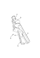
図1および図2を参照すると、針シールド組み立て品20は、針ハブ22と、該針ハブに接続された、もしくは一体化されたベース部材24と、針シールドベース26と針カバー28とを含むものとして提供されている。針シールドベースは、針ハブまたはベース部材と接続可能な基端部と、少なくとも針カニューレ30の一部を覆うための細長いキャビティを含む比較的末端側の部分27とを含んでいる。針シールドベース26の基端部は、一体化したヒンジピン29と湾曲した上面31とを含んでいる。上面31は、針シールドをヒンジピンの周りで回転させるために、ユーザの指と係合されるように設計されている。突起33が湾曲した上面に設けられていてもよい。
With reference to FIGS. 1 and 2, the
針カニューレは、おそらく異なる目的で使用される様々な異なる長さおよびゲージで入手可能である。もし、針シールドが針の軸と係合するロック部材の係合によって保護位置で固定されるのであれば、ロック部材(もしくは複数の部材)が適切に配置されていることが重要である。本発明の針シールドベース26は、所望の長さで成形されるか、もしくは成形工程の後で切断されるかして、特定の針カニューレの長さにあわせて作られることも可能である。
Needle cannulas are available in a variety of different lengths and gauges, possibly used for different purposes. If the needle shield is fixed in the protected position by engagement of a lock member that engages the needle shaft, it is important that the lock member (or members) be properly positioned. The
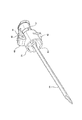
ロック部材34を含む別体のロック組み立て体32が、針シールドベース26の末端部に取り付けられるために設けられている。ロック組み立て体32はほぼU型の断面で、図9に示すようにキャビティ38を定めるキャップ36から構成されている。キャップが、図3に示すように、針シールドベースと連結されているときに、キャップは針シールドベース26の細長いキャビティと軸方向に位置あわせされている。針シールドベースの末端部分とキャップ36との相対的な長さは、図に示されているように異なっていてもよく、一方よりも長いか、双方が同じ長さであってもよい。図に示した好ましい実施形態における針シールドベースのロック部材がないとは言え、キャップと針シールドベースの両方が、針カニューレ軸と係合するための1または複数のロック部材を含んでいてもよい。ロック部材34は、キャップ36と一体化して示されており、キャビティ38の開口部近傍にキャップの対抗する側壁に一方と接続されたベースを有している。ロック部材34は、キャップと連続する針シールドベースが針カニューレを覆うように押し進められると、側壁に向かって屈曲することができる。
A
キャップ36は、接着または溶接または機械的コネクタによって、針シールドベースの末端に固定されていてもよい。針シールドベースの末端部分は開口端部であるのが好ましい一方で、キャップは閉じた末端か、または針カニューレの先端をシールドするために部分的閉じている末端を有しているのが好ましい。キャップの基端部分は開口端部である。針シールド/キャップ組み立て品は様々な異なる方法で製造可能である。針シールドベースとキャップの両方は、ポリプロピレン、ポリエチレン、またはそれらの組み合わせといった適当なプラスチック物質を射出成形してできる。針シールドベースは所定の長さで成形可能であり、また、所定範囲の長さの針カニューレを収容する上で十分な大きさに作ることも可能であり、そして必要に応じて所定の長さに切断することも可能である。さらに、キャップは針シールドに固定されている。
The
針シールドベース26の末端部分が、ぎりぎりでない程度の細長いキャビティを定めるのが好ましく、キャップは装置のキャビティの輪郭だけを定めることができる。針シールドベースの基端部分は、針ハブ22またはベース部材24とロック係合するための突起すなわちタブ40を含んでいてもよい。
The distal portion of the
好ましい実施形態におけるベース部材24は、図3に示すように、針シールドベース26の基端で、ロック突起40を受けるノッチ44を有する突起42を含んでいる。さらに、ベース部材は、針シールドベース上でヒンジピン29を受けるためのアーチ形の壁を有するチャンネル46を含んでいる。図2および図10〜図12に示されているように、チャンネル46はC型突起48と斜面50との間に配置されている。ベース部材24内の円筒形の凹部51は、針カバー28の基端を受けるように設けられている。
The
針ハブはシリンジ52といった医療装置との接続に適した基端を含んでいる。様々なタイプのコネクタが知られており、本発明の範囲内と考えられている。医療装置に固定されると、液体連通が針カニューレ30と装置の内部槽54との間に確立される。
The needle hub includes a proximal end suitable for connection with a medical device such as a
針シールドベース26とそれに関連するロック組み立て体32は互いに針シールドを構成しており、図4及び図6に示す開口位置と、図5及び図8に示す閉じた位置との間でヒンジピン29の周りを回転できるものである。ロック部材34は、針カニューレ30がキャビティ38に入るときに、キャップ36の側壁に向かってずらされる。ひとたび、針カニューレがキャビティの中に十分に移動すると、ロック部材34はもとの位置に跳ね返り、それによって、図9に示すように針カニューレを捕獲する。
The
図13に示されるように、針シールドベース26は選択された長さで製造された末端部分27を有している。ロック組み立て体32は、ロック部材34が使用後の針カニューレ30と係合可能となるように、製造されたシールドベースに固定されてもよい。もし針シールドベースが短い針カニューレを保護するために使用されるならば、例えば線54の例で示されている選択点で、針シールドベースは切断可能である。図15及び図16に図示されているように、針シールドベース26′、26′′は比較的短いおよび長い長さで切断されており、これはロック組み立て体32に固定される前に個々に行われる。
As shown in FIG. 13, the
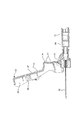
本発明の第2実施形態が図17に示されている。この実施形態において、針シールドベース126が、様々な長さの針カニューレを収容する上で好ましい選択された長さで製造されている。針シールドベースの末端部分127は上面128、対抗する側壁130、細長いキャビティを定める端壁132を含んでいる。一対の開口部134が上面128を貫いて延在している。同じ記号は、先の実施形態のシールドに見られる要素と同様のものを指し示すとして用いられている。
A second embodiment of the invention is shown in FIG. In this embodiment, the
ロック組み立て体136が針シールドベースと連結するために設けられている。ロック組み立て体が、1または複数のロック部材140を有する細長いレールを含んでいる。ロック部材はそれぞれ下方向に延びる壁142と、好ましくは壁142に対して鋭角で上方に伸びる突起144とを含んでいる。ロック部材は弾力があり、針カニューレの軸によって屈曲可能である。それらは、ひとたび針カニューレが捕獲されると、もとの位置に跳ね返る。一対の突起146がレール138から上方に延在している。各突起は、針シールドベースの上面にある開口部134の一つを通って押し込まれることができる細長い端部を有しており、それによって、シールドとのロック係合をもたらす。機械的ロック要素の他のタイプが、シールドベース126とロック組み立て体136との連結に使用され得る。そのような要素は、接着熱杭や他の同様の手段によって結合され得る。
A
図18から図20は、本発明の第3実施形態を示す。この実施形態において、針シールド組み立て品200は上述したものと同様の基端部分を有する針シールドベース226を含んでいる。したがって、同じ数字が同じ部分を示すために使用されている。その末端部分227は、細長いレールの形である。一対の穴228がレールを貫いて伸びている。ロック組み立て体230が針シールドベースの末端と結合するために設けられている。それは、細長い溝236を形成する、上面232と一対の対向する側壁234とを含んでいる。一対の突起238がロック組み立て体の上面232から伸びている。各突起は広がったヘッド240を有する捧239を含み、そのヘッド240は針シールドの末端部分227に設けられた穴228の中に簡単に入るように先細になっていてもよい。これらの要素が図20にもっともよく示されている。1または複数の突起242のそれぞれは、側壁234の一方と一体化されているのが好ましい。突起は、チャンネルの開口部の近くで側壁234と接続されていてもよく、その接続について、側壁に向かって屈曲可能である。ロック組み立て体は図18と図19に示されるように、針シールドベースに2つの向きのどちらかで固定されてもよい。したがって、異なる長さの針が同じ針シールドベースとロック組み立て体に収容されることができる。上述したように、ロック装置の異なるタイプが針シールドベースとロック組み立て体の連結に使用されることが可能である。
18 to 20 show a third embodiment of the present invention. In this embodiment,
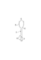
本発明の第4実施形態が図21に示されている。針シールド組み立て品300は、第1及び第2実施形態のものと同様の針シールドベース326から構成されている。同一の記号は、これらの実施形態に見られる針シールドベース、ハブ、ベース部材の共通の要素を指し示すために用いられている。針シールドベース326の末端部分327は、上面を貫いて伸び、細長い針シールドチャンネルの中まで開口する一対の穴328を含んでいる。ロック組み立て体330が、針シールドベースの接続のために設けられている。ロック組み立て体330は、細長いレール332から構成されており、このレールは、レールの上面から上方向に延びる一対の突起333と、レールから下方向に伸びる一対のロック部材334とを有する。各突起333は、針シールドベース326の末端部分327にある穴328を通ってスナップ係合する大きさの広がったヘッドを有する捧を含んでおり、それによって、永久に針シールドとロック組み立て体は連結される。ロック組み立て体334は、レール332の真下で、ほぼV字形の構造で形成されている。(針シールドベース326とロック組み立て体330とから成る)針シールドが閉じられていると、それらは針カニューレの軸によって反り返ることができ、ひとたび、針シールドがいっぱいまで閉じられると、それはもとの位置に向かって跳ね返る。したがって、針カニューレの軸がロック部材334のV字部分の中に捉えられる。より多くの、またはより少数のロック部材が使用され得ることは、理解されるであろう。
A fourth embodiment of the invention is shown in FIG. The
図21から図22に示されているように、ロック組み立て体330の基端部分がベース部材24を収容するために二股に分かれている。その対向する壁336のそれぞれは内側に伸びる突起338を含んでいる。ロック組み立て体が針シールドベースと連結されると、突起はベース部材24上で突起42と係合可能であり、それによって針シールドを閉じた位置である針保護位置に固定することができる。
As shown in FIGS. 21 to 22, the base end portion of the
Claims (6)
該ハブの末端に固定された針カニューレと、
基端部分と末端部分とを有する針シールドベースであって、該基端部分は前記針ハブと回転可能に接続される針シールドベースと、
前記針シールドベースの前記末端部分に連結される別個のロック組み立て体であって、弾力のある少なくとも2個の針係合部材を含む別個のロック組み立て体と、
前記針シールドベースおよび前記ロック組み立て体のうちの少なくとも一方は、前記針カニューレの少なくとも一部分を受け入れるキャビティを含み、
該針シールドベースおよび前記別個のロック組み立て体は、それぞれ、該針シールドベースと該ロック組み立て体とを互いに連結するように、穴、および、該穴に係合される突起を含む針シールド組み立て品。A needle hub having a proximal end and a distal end;
A needle cannula secured to the distal end of the hub;
A needle shield base having a proximal portion and a distal portion, and a needle shield base base end portion that is rotatably connected to the needle hub,
A separate lock assembly coupled to the distal portion of the needle shield base, the separate lock assembly including at least two resilient needle engaging members;
At least one of the needle shield base and the lock assembly includes a cavity for receiving at least a portion of the needle cannula;
The needle shield base and the separate lock assembly each include a hole and a protrusion engaged with the hole to connect the needle shield base and the lock assembly to each other. .
Applications Claiming Priority (2)
| Application Number | Priority Date | Filing Date | Title |
|---|---|---|---|
| US29640601P | 2001-06-06 | 2001-06-06 | |
| PCT/US2002/016800 WO2002098481A2 (en) | 2001-06-06 | 2002-05-29 | Hinged needle shield assembly having needle cannula lock |
Publications (3)
| Publication Number | Publication Date |
|---|---|
| JP2004528136A JP2004528136A (en) | 2004-09-16 |
| JP2004528136A5 JP2004528136A5 (en) | 2006-01-05 |
| JP4478448B2 true JP4478448B2 (en) | 2010-06-09 |
Family
ID=23141876
Family Applications (1)
| Application Number | Title | Priority Date | Filing Date |
|---|---|---|---|
| JP2003501518A Expired - Lifetime JP4478448B2 (en) | 2001-06-06 | 2002-05-29 | Hinge needle shield assembly with needle cannula lock |
Country Status (10)
| Country | Link |
|---|---|
| US (1) | US7220249B2 (en) |
| EP (1) | EP1401517B1 (en) |
| JP (1) | JP4478448B2 (en) |
| CN (1) | CN1287875C (en) |
| BR (2) | BRPI0210203A2 (en) |
| CA (1) | CA2449324C (en) |
| ES (1) | ES2402410T3 (en) |
| MX (1) | MXPA03011156A (en) |
| WO (1) | WO2002098481A2 (en) |
| ZA (1) | ZA200309461B (en) |
Families Citing this family (28)
| Publication number | Priority date | Publication date | Assignee | Title |
|---|---|---|---|---|
| US6648855B2 (en) * | 1999-08-23 | 2003-11-18 | Becton, Dickinson And Company | Safety needle assembly |
| US7413562B2 (en) | 2001-03-15 | 2008-08-19 | Specialized Health Products, Inc. | Safety shield for medical needles |
| EP1401514B1 (en) | 2001-05-22 | 2008-10-22 | Becton, Dickinson and Company | Needle shield assembly having hinged needle shield |
| EP1380315A1 (en) * | 2002-06-12 | 2004-01-14 | Becton, Dickinson and Company | Safety needle assembly |
| FR2869806B1 (en) * | 2004-05-07 | 2007-04-27 | Perouse Soc Par Actions Simpli | INJECTION DEVICE WITH EXTRACTION MECHANISM |
| DE102004039408A1 (en) * | 2004-08-13 | 2006-03-02 | Disetronic Licensing Ag | Insertion head for medical or pharmaceutical applications |
| WO2006113675A2 (en) * | 2005-04-18 | 2006-10-26 | Specialized Health Products, Inc. | Methods of manufacturing safety shields for medical needles and related manufacturing devices |
| US20060258991A1 (en) * | 2005-04-29 | 2006-11-16 | Lin Edward D | Portable needle uncapping and recapping device |
| US7744567B2 (en) * | 2006-11-22 | 2010-06-29 | Becton, Dickinson And Company | Reducing withdrawal force in a safety IV catheter |
| US8038654B2 (en) | 2007-02-26 | 2011-10-18 | Becton, Dickinson And Company | Syringe having a hinged needle shield |
| EP1970091B1 (en) * | 2007-03-14 | 2010-10-27 | F. Hoffmann-La Roche AG | Insertion head for medical or pharmaceutical applications |
| DE502007004715D1 (en) * | 2007-03-14 | 2010-09-23 | Hoffmann La Roche | Insertion device for an insertion head, in particular for an infusion set |
| JP5457457B2 (en) * | 2008-09-18 | 2014-04-02 | ベクトン・ディキンソン・アンド・カンパニー | Container for an injection device having an injection needle |
| US8323249B2 (en) | 2009-08-14 | 2012-12-04 | The Regents Of The University Of Michigan | Integrated vascular delivery system |
| WO2011146772A1 (en) | 2010-05-19 | 2011-11-24 | Tangent Medical Technologies Llc | Safety needle system operable with a medical device |
| US8771230B2 (en) | 2010-05-19 | 2014-07-08 | Tangent Medical Technologies, Llc | Integrated vascular delivery system |
| JP6139409B2 (en) | 2010-11-22 | 2017-05-31 | ベー・ブラウン・メルズンゲン・アクチエンゲゼルシャフトB.Braun Melsungen Aktiengesellschaft | Hinged shield assembly and associated method |
| AU2012335825B2 (en) | 2011-11-07 | 2017-02-16 | Safety Syringes, Inc. | Contact trigger release needle guard |
| TWM434595U (en) * | 2011-12-20 | 2012-08-01 | zhi-yun Li | Safe liquid delivering needle |
| US10350366B2 (en) | 2013-02-01 | 2019-07-16 | Nxstage Medical, Inc. | Safe cannulation devices, methods, and systems |
| CA2937744C (en) | 2014-02-04 | 2022-08-09 | Icu Medical, Inc. | Self-priming systems and methods |
| US9867951B2 (en) | 2014-04-08 | 2018-01-16 | B. Braun Melsungen Ag | Hinged cap needle assemblies and related methods |
| US10029049B2 (en) | 2015-03-19 | 2018-07-24 | B. Braun Melsungen Ag | Hinged shield assemblies and related methods |
| JP7047271B2 (en) * | 2017-07-14 | 2022-04-05 | ニプロ株式会社 | Needle assembly and needle device equipped with it |
| USD880690S1 (en) * | 2018-07-26 | 2020-04-07 | Laborie Medical Technologies Corp. | Pressure catheter connector |
| USD969314S1 (en) | 2020-12-14 | 2022-11-08 | Expressions Design Studio, LLC | Blood collection safety needle |
| USD968591S1 (en) | 2020-12-14 | 2022-11-01 | Expressions Design Studio, LLC | Safety needle |
| US11207469B1 (en) | 2021-03-04 | 2021-12-28 | Expressions Design Studio, LLC | Low deadspace syringe including a pivoting needle guard |
Family Cites Families (101)
| Publication number | Priority date | Publication date | Assignee | Title |
|---|---|---|---|---|
| US1779451A (en) | 1929-02-01 | 1930-10-28 | Sponsel Charles | Hypodermic-syringe guard |
| US2004050A (en) | 1934-07-26 | 1935-06-04 | Bishop & Company Platinum Work | Hypodermic needle package |
| US2700385A (en) | 1951-07-10 | 1955-01-25 | Ortiz Mariano | Obstetrical needle |
| US2836942A (en) | 1953-11-16 | 1958-06-03 | Pfizer & Co C | Method of encasing and sterilizing needles |
| US3021942A (en) | 1957-06-27 | 1962-02-20 | Baxter Don Inc | Needle package |
| US2953243A (en) | 1957-07-25 | 1960-09-20 | Roehr Zbislaw Maciej | Disposable needle assembly |
| US2854976A (en) | 1957-08-28 | 1958-10-07 | Heydrich Sergio Esnard | Protective device for needles of hypodermic syringes |
| BE626565A (en) | 1959-10-28 | |||
| US3074542A (en) | 1960-01-06 | 1963-01-22 | Myerson Tooth Corp | Package for hypodermic needles |
| US3329146A (en) | 1963-10-02 | 1967-07-04 | Baxter Laboratories Inc | Needle container |
| US3255873A (en) | 1963-10-11 | 1966-06-14 | Propper Mfg Company Inc | Combination sealing and dispensing device |
| US3323523A (en) | 1964-11-18 | 1967-06-06 | Abbott Lab | Intravenous catheter assembly with divisible needle sheath portions |
| US3333682A (en) | 1965-08-18 | 1967-08-01 | Burron Medical Prod Inc | Disposable needle container |
| US3294231A (en) | 1965-11-01 | 1966-12-27 | Becton Dickinson Co | Dental needle shield |
| US3367488A (en) | 1966-11-16 | 1968-02-06 | Pharmaseal Lab | Hypodermic syringe package |
| US3610240A (en) | 1967-06-13 | 1971-10-05 | American Hospital Supply Corp | Intravenous catheter apparatus with catheter telescoped inside puncturing cannula |
| US3485239A (en) | 1967-11-02 | 1969-12-23 | Becton Dickinson Co | Self-contained sterile syringe |
| US3537452A (en) | 1968-11-18 | 1970-11-03 | Bard Inc C R | Needle cover and bevel guard |
| US3828775A (en) | 1969-02-06 | 1974-08-13 | Iso Nuclear Corp | Self-packaged hypodermic syringe |
| US3658061A (en) | 1970-11-10 | 1972-04-25 | Baxter Laboratories Inc | Needle guard |
| US3890971A (en) | 1973-10-23 | 1975-06-24 | Thomas A Leeson | Safety syringe |
| US3934722A (en) | 1974-08-26 | 1976-01-27 | American Hospital Supply Corporation | Sterile needle package |
| US3904033A (en) | 1974-11-08 | 1975-09-09 | Xomox Corp | Pick-guard |
| US3968876A (en) | 1975-03-19 | 1976-07-13 | Brookfield Richard A | Sealed container with a sterilized hypodermic needle within it and method for effecting the sealing thereof |
| USRE31086E (en) | 1976-09-10 | 1982-11-23 | W. R. Grace & Co., Cryovac Division | Plastic hinge construction |
| US4139009A (en) | 1976-11-23 | 1979-02-13 | Marcial Alvarez | Hypodermic needle assembly with retractable needle cover |
| US4113090A (en) | 1977-08-15 | 1978-09-12 | Becton, Dickinson And Company | Medical instrument package |
| US4175008A (en) | 1978-06-26 | 1979-11-20 | Bio-Pharmaceutical Packaging Corp. | Culture specimen collection and transport package |
| US4300678A (en) | 1980-04-07 | 1981-11-17 | Becton, Dickinson And Company | Syringe package with evidence of opening |
| US4375849A (en) | 1981-05-15 | 1983-03-08 | Sage Products, Inc. | Syringe needle removal and disposal device |
| US4430082A (en) | 1982-06-25 | 1984-02-07 | Hoffmann-La Roche Inc. | Hypodermic syringe assembly |
| US4643722A (en) | 1983-04-05 | 1987-02-17 | Smith Jr William I | Closure system for storage, transport and disposal of hypodermic needles |
| IT1195487B (en) | 1983-12-29 | 1988-10-19 | Sasib Spa | INVERTER CIGARETTE DEVICE WITH FILTER |
| US4664259A (en) | 1985-05-13 | 1987-05-12 | Robert Landis | Needle container and method for preventing accidental contact with a needle |
| US4671408A (en) | 1985-06-20 | 1987-06-09 | Burron Medical Inc. | Temper-resistant protective capping device for filled syringes |
| US4826490A (en) | 1985-07-29 | 1989-05-02 | National Research Development Corporation | Safety device for hypodermic needle or the like |
| US4592744A (en) | 1985-08-14 | 1986-06-03 | The University Of Virginia Alumni Patents Foundation | Self-resheathing needle assembly |
| US4634428A (en) | 1985-08-15 | 1987-01-06 | Cuu Cwo Liang | Cover for a disposable syringe |
| WO1987002254A1 (en) | 1985-10-11 | 1987-04-23 | Physionic Gesellschaft Für Medizin- Und Systemtech | Injection syringe |
| DE8531274U1 (en) | 1985-11-06 | 1986-01-09 | Basf Ag, 6700 Ludwigshafen | Box-shaped containers for objects |
| US4659330A (en) | 1985-11-08 | 1987-04-21 | Robert Nelson | Hypodermic syringe needle guard |
| US4743233A (en) | 1986-01-23 | 1988-05-10 | Schneider Medical Technologies, Inc. | Safety cap syringe |
| US4695274A (en) | 1986-01-31 | 1987-09-22 | Fox Richard L | Protected hypodermic needle |
| US4664654A (en) | 1986-03-07 | 1987-05-12 | Strauss Eric C | Automatic protracting and locking hypodermic needle guard |
| US4681567A (en) | 1986-04-03 | 1987-07-21 | Masters Edwin J | Syringe with safety sheath |
| US4778453A (en) | 1986-04-07 | 1988-10-18 | Icu Medical, Inc. | Medical device |
| US4735311A (en) | 1986-04-09 | 1988-04-05 | The West Company | Needle shield assembly |
| US4801295A (en) | 1986-05-22 | 1989-01-31 | Spencer Treesa A | Disposable hypodermic syringe and needle combination having retractable, accident preventing sheath |
| US4702738A (en) | 1986-05-22 | 1987-10-27 | Spencer Treesa A | Disposable hypodermic syringe and needle combination having retractable, accident preventing sheath |
| US4731059A (en) | 1986-10-14 | 1988-03-15 | Medical Safety Products, Inc. | Combination needle shield/needle guard device positively locked onto detachable needle assemblies for an evacuated blood collection system and a hypodermic syringe |
| US4723943A (en) | 1986-12-31 | 1988-02-09 | Montana Deaconess Medical Center | Sheathed syringe |
| US4795432A (en) | 1987-02-19 | 1989-01-03 | Karczmer Claude M | Shield assembly for hypodermic injection devices |
| US4737144A (en) | 1987-03-09 | 1988-04-12 | Choksi Pradip V | Syringe with selectively exposed and enveloped needle |
| CA1285441C (en) | 1987-03-17 | 1991-07-02 | Roy D. Mcnaughton | Mcnaughton syringe shield type b |
| US4782841A (en) | 1987-04-07 | 1988-11-08 | Icu Medical, Inc. | Medical device |
| US4816024A (en) | 1987-04-13 | 1989-03-28 | Icu Medical, Inc. | Medical device |
| US4728321A (en) | 1987-04-16 | 1988-03-01 | Ming-Chiu Wu | Syringe cap with adhesive holding plug |
| US4795443A (en) | 1987-04-16 | 1989-01-03 | Peachtree Medical, Inc. | Syringe sealing device and method |
| US4728320A (en) | 1987-04-17 | 1988-03-01 | Chen Chang Cheng | Syringe cap with hammer |
| US4747837A (en) | 1987-05-01 | 1988-05-31 | Hauck Martin W | Syringe needle recapping protective device |
| US4772272A (en) | 1987-05-11 | 1988-09-20 | Mcfarland Barton C | Needle protective sleeve |
| US4738663A (en) | 1987-06-04 | 1988-04-19 | Bogan David B | Hypodermic needle shield |
| US4746008A (en) | 1987-07-01 | 1988-05-24 | Heverly Karen H | Child-resistant box for storage of hazardous materials |
| US4874384A (en) | 1987-07-13 | 1989-10-17 | International Medical Innovators, Inc. | Needle safety guard |
| US4842587A (en) | 1987-07-15 | 1989-06-27 | Poncy George W | No-prick hypodermic syringe |
| US4838871A (en) | 1987-07-17 | 1989-06-13 | Luther Ronald B | Needle guard, and assembly |
| US4747836A (en) * | 1987-07-17 | 1988-05-31 | Luther Medical Products, Inc. | Needle guard, and assembly |
| US4735618A (en) | 1987-07-20 | 1988-04-05 | Henry E. Szachowicz, Jr. | Protective enclosure for hypodermic syringe |
| US4826491A (en) | 1987-07-27 | 1989-05-02 | Schramm James J | Needle bearing medical device with three-position shield |
| US4850968A (en) | 1987-07-27 | 1989-07-25 | Ar.Ma.S.R.L. | Self-blocking hypodermic syringe for once-only use, comprising a needle protection cap |
| US4790828A (en) | 1987-08-07 | 1988-12-13 | Dombrowski Mitchell P | Self-capping needle assembly |
| US4804372A (en) | 1987-09-08 | 1989-02-14 | Laico Joseph P | Protective sheath for hypodermic needle |
| US4819659A (en) | 1987-09-21 | 1989-04-11 | Icu Medical, Inc. | Blood withdrawal device with movable needle guard member |
| US4850973A (en) | 1987-10-16 | 1989-07-25 | Pavel Jordon & Associates | Plastic device for injection and obtaining blood samples |
| US4850978A (en) | 1987-10-29 | 1989-07-25 | Baxter International Inc. | Drug delivery cartridge with protective cover |
| US4863436A (en) | 1987-11-03 | 1989-09-05 | Iatroban, Ltd. | Hypodermic needle with protective cover |
| US4813426A (en) | 1987-11-09 | 1989-03-21 | Habley Medical Technology Corporation | Shielded safety syringe having a retractable needle |
| US4781697A (en) | 1987-12-04 | 1988-11-01 | Robert Slaughter | Removable protective shield for needle sheath |
| US4816022A (en) | 1987-12-07 | 1989-03-28 | Poncy George W | Hypodermic syringe with sliding cap |
| US4892107A (en) | 1988-01-05 | 1990-01-09 | Habley Medical Technology Corp. | Single use, safety blood collection device |
| US4850977A (en) | 1988-01-29 | 1989-07-25 | Bayless William B | Button activated automatic needle sheath for disposable syringe |
| US4863434A (en) | 1988-01-29 | 1989-09-05 | Bayless William B | Automatic needle sheath for disposable syringe |
| US4820277A (en) | 1988-02-16 | 1989-04-11 | Norelli Robert A | Safety cover for syringe needles |
| US4850996A (en) | 1988-02-22 | 1989-07-25 | Cree Ian C | Safety needle |
| US4850976A (en) | 1988-04-08 | 1989-07-25 | The Cloverline, Inc. | Combination sheath and foldable shield for hypodermic syringe needle |
| US4883469A (en) | 1988-04-08 | 1989-11-28 | Glazier Stephen C | Guard assembly for hypodermic needle |
| US4886503A (en) | 1988-05-23 | 1989-12-12 | University Medical Center, Inc. | Disposable covered needle for syringe |
| US4944397A (en) | 1988-05-23 | 1990-07-31 | University Medical Center, Inc. | Disposable covered needle for syringe |
| US4867746A (en) | 1988-05-23 | 1989-09-19 | Becton, Dickinson And Company | Needle shield |
| US4888001A (en) | 1988-06-01 | 1989-12-19 | Schoenberg Stephen J | Cover for a disposable hypodermic needle |
| US4900309A (en) | 1988-06-02 | 1990-02-13 | Fred Netherton | Needle shield |
| US4846796A (en) | 1988-07-27 | 1989-07-11 | Rialto Enterprises, Ltd. | Protective system for safe disposition of a syringe and hypodermic injection device carried thereon |
| US4892521A (en) | 1988-08-03 | 1990-01-09 | Lincoln Mills, Inc. | Protective cover for hypodermic needle |
| US4863435A (en) | 1988-08-24 | 1989-09-05 | Sturman Martin F | Safety hypodermic syringe |
| US4966591A (en) | 1988-10-20 | 1990-10-30 | Frank Yuen | Needle assembly |
| US4872552A (en) | 1988-11-16 | 1989-10-10 | Mid-South Products Engineering, Inc. | Safety packaging for hypodermic syringes with needles and the like |
| GB2225723B (en) | 1988-12-06 | 1992-05-13 | Patrick Han | "disposable covered needle safety assembly" |
| US4921096A (en) | 1989-01-17 | 1990-05-01 | Taut, Inc. | Package assembly |
| US5509907A (en) * | 1996-03-17 | 1996-04-23 | Med-Safe Products, Inc. | Syringe needle guard assembly |
| US5807351A (en) * | 1996-06-17 | 1998-09-15 | Safegard Medical Products, Inc. | Protection device for sharp objects |
| US5632732A (en) * | 1996-09-11 | 1997-05-27 | Becton, Dickinson And Company | Needle assembly having single handedly activated shield |
-
2002
- 2002-05-29 US US10/479,811 patent/US7220249B2/en not_active Expired - Lifetime
- 2002-05-29 MX MXPA03011156A patent/MXPA03011156A/en active IP Right Grant
- 2002-05-29 EP EP02737225A patent/EP1401517B1/en not_active Expired - Lifetime
- 2002-05-29 CA CA2449324A patent/CA2449324C/en not_active Expired - Lifetime
- 2002-05-29 ES ES02737225T patent/ES2402410T3/en not_active Expired - Lifetime
- 2002-05-29 WO PCT/US2002/016800 patent/WO2002098481A2/en active Application Filing
- 2002-05-29 BR BRPI0210203A patent/BRPI0210203A2/en active IP Right Grant
- 2002-05-29 BR BRPI0210203A patent/BRPI0210203B8/en unknown
- 2002-05-29 CN CNB028153383A patent/CN1287875C/en not_active Expired - Lifetime
- 2002-05-29 JP JP2003501518A patent/JP4478448B2/en not_active Expired - Lifetime
-
2003
- 2003-12-05 ZA ZA2003/09461A patent/ZA200309461B/en unknown
Also Published As
| Publication number | Publication date |
|---|---|
| BRPI0210203A2 (en) | 2016-10-25 |
| WO2002098481A2 (en) | 2002-12-12 |
| EP1401517B1 (en) | 2013-01-02 |
| EP1401517A4 (en) | 2009-11-11 |
| BRPI0210203B1 (en) | 2018-06-12 |
| MXPA03011156A (en) | 2004-02-26 |
| BRPI0210203B8 (en) | 2021-06-22 |
| ZA200309461B (en) | 2005-07-27 |
| JP2004528136A (en) | 2004-09-16 |
| CA2449324A1 (en) | 2002-12-12 |
| US7220249B2 (en) | 2007-05-22 |
| ES2402410T3 (en) | 2013-05-03 |
| CN1287875C (en) | 2006-12-06 |
| US20040215154A1 (en) | 2004-10-28 |
| EP1401517A2 (en) | 2004-03-31 |
| CN1538858A (en) | 2004-10-20 |
| CA2449324C (en) | 2010-07-20 |
| WO2002098481A3 (en) | 2003-05-22 |
Similar Documents
| Publication | Publication Date | Title |
|---|---|---|
| JP4478448B2 (en) | Hinge needle shield assembly with needle cannula lock | |
| JP4377222B2 (en) | Needle shield assembly with hinged needle shield and flexible cannula lock | |
| JP4350952B2 (en) | Needle shield assembly with hinged needle shield | |
| JP5730919B2 (en) | Injection needle device | |
| JP5520255B2 (en) | Safety needle device | |
| US6413243B1 (en) | Apparatus for covering a used syringe needle | |
| US20050090784A1 (en) | Medical puncturing device | |
| US20050020972A1 (en) | Catheter head with catheter drain in discrete rotational positions | |
| JP2008529657A (en) | Needle guard | |
| JPH06315532A (en) | Safety device that is used with needle | |
| JP3923246B2 (en) | Drug injector | |
| AU2007237361B2 (en) | Hinged needle shield assembly having needle cannula lock | |
| AU2002310165A1 (en) | Hinged needle shield assembly having needle cannula lock | |
| JP2019022612A (en) | Needle assembly | |
| AU2002311867A1 (en) | Needle shield assembly having hinged needle shield |
Legal Events
| Date | Code | Title | Description |
|---|---|---|---|
| A521 | Request for written amendment filed |
Free format text: JAPANESE INTERMEDIATE CODE: A523 Effective date: 20050530 |
|
| A621 | Written request for application examination |
Free format text: JAPANESE INTERMEDIATE CODE: A621 Effective date: 20050530 |
|
| A131 | Notification of reasons for refusal |
Free format text: JAPANESE INTERMEDIATE CODE: A131 Effective date: 20080715 |
|
| A601 | Written request for extension of time |
Free format text: JAPANESE INTERMEDIATE CODE: A601 Effective date: 20081015 |
|
| A602 | Written permission of extension of time |
Free format text: JAPANESE INTERMEDIATE CODE: A602 Effective date: 20081022 |
|
| A601 | Written request for extension of time |
Free format text: JAPANESE INTERMEDIATE CODE: A601 Effective date: 20081114 |
|
| A602 | Written permission of extension of time |
Free format text: JAPANESE INTERMEDIATE CODE: A602 Effective date: 20081121 |
|
| A601 | Written request for extension of time |
Free format text: JAPANESE INTERMEDIATE CODE: A601 Effective date: 20081215 |
|
| A602 | Written permission of extension of time |
Free format text: JAPANESE INTERMEDIATE CODE: A602 Effective date: 20081222 |
|
| A521 | Request for written amendment filed |
Free format text: JAPANESE INTERMEDIATE CODE: A523 Effective date: 20090115 |
|
| A02 | Decision of refusal |
Free format text: JAPANESE INTERMEDIATE CODE: A02 Effective date: 20090630 |
|
| A521 | Request for written amendment filed |
Free format text: JAPANESE INTERMEDIATE CODE: A523 Effective date: 20091102 |
|
| RD13 | Notification of appointment of power of sub attorney |
Free format text: JAPANESE INTERMEDIATE CODE: A7433 Effective date: 20091105 |
|
| A521 | Request for written amendment filed |
Free format text: JAPANESE INTERMEDIATE CODE: A821 Effective date: 20091105 |
|
| A911 | Transfer to examiner for re-examination before appeal (zenchi) |
Free format text: JAPANESE INTERMEDIATE CODE: A911 Effective date: 20091130 |
|
| A131 | Notification of reasons for refusal |
Free format text: JAPANESE INTERMEDIATE CODE: A131 Effective date: 20100129 |
|
| A521 | Request for written amendment filed |
Free format text: JAPANESE INTERMEDIATE CODE: A523 Effective date: 20100205 |
|
| TRDD | Decision of grant or rejection written | ||
| A01 | Written decision to grant a patent or to grant a registration (utility model) |
Free format text: JAPANESE INTERMEDIATE CODE: A01 Effective date: 20100305 |
|
| A01 | Written decision to grant a patent or to grant a registration (utility model) |
Free format text: JAPANESE INTERMEDIATE CODE: A01 |
|
| A61 | First payment of annual fees (during grant procedure) |
Free format text: JAPANESE INTERMEDIATE CODE: A61 Effective date: 20100315 |
|
| R150 | Certificate of patent or registration of utility model |
Ref document number: 4478448 Country of ref document: JP Free format text: JAPANESE INTERMEDIATE CODE: R150 Free format text: JAPANESE INTERMEDIATE CODE: R150 |
|
| FPAY | Renewal fee payment (event date is renewal date of database) |
Free format text: PAYMENT UNTIL: 20130319 Year of fee payment: 3 |
|
| FPAY | Renewal fee payment (event date is renewal date of database) |
Free format text: PAYMENT UNTIL: 20130319 Year of fee payment: 3 |
|
| FPAY | Renewal fee payment (event date is renewal date of database) |
Free format text: PAYMENT UNTIL: 20140319 Year of fee payment: 4 |
|
| R250 | Receipt of annual fees |
Free format text: JAPANESE INTERMEDIATE CODE: R250 |
|
| R250 | Receipt of annual fees |
Free format text: JAPANESE INTERMEDIATE CODE: R250 |
|
| R250 | Receipt of annual fees |
Free format text: JAPANESE INTERMEDIATE CODE: R250 |
|
| R250 | Receipt of annual fees |
Free format text: JAPANESE INTERMEDIATE CODE: R250 |
|
| R250 | Receipt of annual fees |
Free format text: JAPANESE INTERMEDIATE CODE: R250 |
|
| R250 | Receipt of annual fees |
Free format text: JAPANESE INTERMEDIATE CODE: R250 |
|
| R250 | Receipt of annual fees |
Free format text: JAPANESE INTERMEDIATE CODE: R250 |
|
| R250 | Receipt of annual fees |
Free format text: JAPANESE INTERMEDIATE CODE: R250 |
|
| R250 | Receipt of annual fees |
Free format text: JAPANESE INTERMEDIATE CODE: R250 |
|
| R250 | Receipt of annual fees |
Free format text: JAPANESE INTERMEDIATE CODE: R250 |
|
| EXPY | Cancellation because of completion of term |