JP2008529657A - Needle guard - Google Patents
Needle guard Download PDFInfo
- Publication number
- JP2008529657A JP2008529657A JP2007555099A JP2007555099A JP2008529657A JP 2008529657 A JP2008529657 A JP 2008529657A JP 2007555099 A JP2007555099 A JP 2007555099A JP 2007555099 A JP2007555099 A JP 2007555099A JP 2008529657 A JP2008529657 A JP 2008529657A
- Authority
- JP
- Japan
- Prior art keywords
- needle
- needle guard
- hub
- insertion device
- guard
- Prior art date
- Legal status (The legal status is an assumption and is not a legal conclusion. Google has not performed a legal analysis and makes no representation as to the accuracy of the status listed.)
- Pending
Links
Images


Classifications
-
- A—HUMAN NECESSITIES
- A61—MEDICAL OR VETERINARY SCIENCE; HYGIENE
- A61M—DEVICES FOR INTRODUCING MEDIA INTO, OR ONTO, THE BODY; DEVICES FOR TRANSDUCING BODY MEDIA OR FOR TAKING MEDIA FROM THE BODY; DEVICES FOR PRODUCING OR ENDING SLEEP OR STUPOR
- A61M25/00—Catheters; Hollow probes
- A61M25/01—Introducing, guiding, advancing, emplacing or holding catheters
- A61M25/06—Body-piercing guide needles or the like
- A61M25/0612—Devices for protecting the needle; Devices to help insertion of the needle, e.g. wings or holders
-
- A—HUMAN NECESSITIES
- A61—MEDICAL OR VETERINARY SCIENCE; HYGIENE
- A61M—DEVICES FOR INTRODUCING MEDIA INTO, OR ONTO, THE BODY; DEVICES FOR TRANSDUCING BODY MEDIA OR FOR TAKING MEDIA FROM THE BODY; DEVICES FOR PRODUCING OR ENDING SLEEP OR STUPOR
- A61M25/00—Catheters; Hollow probes
- A61M25/01—Introducing, guiding, advancing, emplacing or holding catheters
- A61M25/02—Holding devices, e.g. on the body
- A61M2025/028—Holding devices, e.g. on the body having a mainly rigid support structure
-
- A—HUMAN NECESSITIES
- A61—MEDICAL OR VETERINARY SCIENCE; HYGIENE
- A61M—DEVICES FOR INTRODUCING MEDIA INTO, OR ONTO, THE BODY; DEVICES FOR TRANSDUCING BODY MEDIA OR FOR TAKING MEDIA FROM THE BODY; DEVICES FOR PRODUCING OR ENDING SLEEP OR STUPOR
- A61M5/00—Devices for bringing media into the body in a subcutaneous, intra-vascular or intramuscular way; Accessories therefor, e.g. filling or cleaning devices, arm-rests
- A61M5/178—Syringes
- A61M5/31—Details
- A61M5/32—Needles; Details of needles pertaining to their connection with syringe or hub; Accessories for bringing the needle into, or holding the needle on, the body; Devices for protection of needles
- A61M5/3205—Apparatus for removing or disposing of used needles or syringes, e.g. containers; Means for protection against accidental injuries from used needles
- A61M5/321—Means for protection against accidental injuries by used needles
- A61M5/3213—Caps placed axially onto the needle, e.g. equipped with finger protection guards
-
- A—HUMAN NECESSITIES
- A61—MEDICAL OR VETERINARY SCIENCE; HYGIENE
- A61M—DEVICES FOR INTRODUCING MEDIA INTO, OR ONTO, THE BODY; DEVICES FOR TRANSDUCING BODY MEDIA OR FOR TAKING MEDIA FROM THE BODY; DEVICES FOR PRODUCING OR ENDING SLEEP OR STUPOR
- A61M5/00—Devices for bringing media into the body in a subcutaneous, intra-vascular or intramuscular way; Accessories therefor, e.g. filling or cleaning devices, arm-rests
- A61M5/178—Syringes
- A61M5/31—Details
- A61M5/32—Needles; Details of needles pertaining to their connection with syringe or hub; Accessories for bringing the needle into, or holding the needle on, the body; Devices for protection of needles
- A61M5/3205—Apparatus for removing or disposing of used needles or syringes, e.g. containers; Means for protection against accidental injuries from used needles
- A61M5/321—Means for protection against accidental injuries by used needles
- A61M5/3216—Caps placed transversally onto the needle, e.g. pivotally attached to the needle base
Abstract
一般に輸液セットと共に使用される挿入デバイス(18)用の針ガード(17)。挿入デバイスの針は通常、一端が穿刺に構成され、反対側の端部にハブを備えている。針ガードは挿入デバイスを受けるように構成された開口部(7)、及び針ガード内で挿入デバイスを固定するように構成された係止機構を含む。廃棄処分のために針ハブを針ガード内に押し込むことによって、針が覆われると、針ハブの突起部が針ガードの内側のアンダーカット部(10、11)と対合し、針ハブを一位置に固定して、針との意図せぬ接触が防止される。 Needle guard (17) for insertion device (18) commonly used with infusion sets. The needle of an insertion device is usually configured with a puncture at one end and a hub at the opposite end. The needle guard includes an opening (7) configured to receive the insertion device and a locking mechanism configured to secure the insertion device within the needle guard. When the needle is covered by pushing the needle hub into the needle guard for disposal, the protrusions of the needle hub are aligned with the undercuts (10, 11) inside the needle guard, and the needle hub is aligned. Fixed in position to prevent unintentional contact with the needle.
Description
本発明の実施形態は、一般に、流体、薬物、又は他の輸液(infusant)を皮下に送達するための輸液セットの一部を形成する軟性カニューレを挿入するための患者の部位の皮下穿刺に通常使用される挿入デバイスに関する。本発明の実施形態は、より詳細には、針から受ける、意図せぬ有害な外傷を受ける危険を防止することができる針ガードに関するものである。 Embodiments of the present invention are typically used for subcutaneous puncture of a patient site for insertion of a flexible cannula that forms part of an infusion set for delivering fluids, drugs, or other infusants subcutaneously. Relates to the insertion device used. Embodiments of the present invention relate more particularly to a needle guard that can prevent the risk of unintended and harmful trauma received from a needle.
流体、薬剤、又は他の輸液を患者の注入部位に送達するには皮下輸液セットが使用される。こうしたデバイスは一般に、輸液ポンプに連結された送達管、又は他の流体あるいは薬剤送達デバイスを備える。こうした輸液セットは、患者の皮膚内に挿入されるカニューレを備えたベース部分を含み得る。カニューレは挿入デバイスの助けにより患者の皮膚内に挿入される。カニューレを、カニューレハウジングのベースに付着された接着剤を使用して注入部位で定位置に保持することができる。それによって、輸液セットを輸液システムの他の部分から分離して、患者をより快適にすることができるようになる。 Subcutaneous infusion sets are used to deliver fluids, drugs, or other infusions to the patient's infusion site. Such devices generally comprise a delivery tube connected to an infusion pump, or other fluid or drug delivery device. Such an infusion set may include a base portion with a cannula that is inserted into the patient's skin. The cannula is inserted into the patient's skin with the aid of an insertion device. The cannula can be held in place at the injection site using an adhesive attached to the base of the cannula housing. Thereby, the infusion set can be separated from other parts of the infusion system to make the patient more comfortable.
カニューレの使用によって患者の快適性がさらに向上される。カニューレは剛性の針よりも可撓性がありので、ユーザは、痛みや不快をかなり低減させて使用することができるようになる。カニューレは運動性を向上させることができるが、他の理由から患者に不便な点が依然として残る。カニューレを定位置に挿入するには一般に針を備える挿入デバイスが使用され、カニューレが注入部位に取り付けられた後に廃棄される。したがって、カニューレから針ハブを引き抜くときに、針の露出された端部から意図せぬ損傷を受ける危険性がある。 The use of a cannula further improves patient comfort. The cannula is more flexible than a rigid needle, allowing the user to use it with significantly reduced pain and discomfort. Although the cannula can improve motility, it still remains inconvenient for the patient for other reasons. An insertion device with a needle is typically used to insert the cannula into place and is discarded after the cannula is attached to the injection site. Thus, there is a risk of unintentional damage from the exposed end of the needle when withdrawing the needle hub from the cannula.
針の廃棄処分中又はその後に傷害を受ける危険があるため、針を迅速かつ安全に覆うことができれば有益である。場合によっては患者が針の容器を簡単に入手することができないため、針の容器又は他の適した容器が使用可能になるまで、挿入デバイス及び針を自分のポケット、財布、手提げなどに入れて持ち運ぶことがある。よって、保護範囲はプロセス全体に耐え、最終の廃棄位置に到達した後は固定されたままでなければならない。 It would be beneficial if the needle could be covered quickly and safely because of the risk of injury during or after needle disposal. In some cases, patients cannot easily obtain a needle container, so place the insertion device and needle in their pocket, purse, handbag, etc. until a needle container or other suitable container is available. May be carried around. Thus, the protection range must withstand the entire process and remain fixed after reaching the final disposal position.
したがって、出荷の状態では挿入デバイスの針を簡単に覆うことができ、出荷中に針が損傷を受けないように保護し、使用後に人が露出した針に触れる危険性を低減する、安全で便利な針ガードを提供することが有用であろう。針ガードを備えた挿入デバイスが特許文献1に記載されている。この挿入デバイスは、針、カニューレハウジング、接着パッチ、及び針ガードを備える。針ガードは、針を覆う他に、挿入デバイス全体を固定するように操作することができるシールドを備えている。
Therefore, the needle of the insertion device can be easily covered in the shipping state, protecting the needle from damage during shipping and reducing the risk of touching the exposed needle after use, safe and convenient It would be useful to provide a simple needle guard. An insertion device having a needle guard is described in
しかし幾つかの従来の周知の針ガードにより、意図せぬ有害な針による穿刺を防止する方法が提案されてきたが、共通の欠点がある。先ず、他の周知の針ガードは、針を保護するために小さく扱い難い部片を使用することが多い。さらに、こうした針ガードは通常、ユーザが針を固定するために、ある複雑な操作の形で部片を嵌め合わせる必要がある。厄介な組立プロセスはさらに時間及び空間を要し、組立プロセス自体が針による穿刺の危険性をさらに増すことになる。
本発明の一実施形態により、通常、外部輸液システムと結合される挿入デバイスと共に使用可能な針ガードが開発された。たとえば、本発明の針ガードで覆うことができる挿入デバイスは、参照により本明細書に組み込まれることとする、米国特許第6,520,938号明細書及び同第6,056,718号明細書に記載されたものでもよい。他の例は、参照により本明細書に組み込まれることとする、2004年12月3日に出願の「Medication Infusion Set」という発明名称の同時係属中である米国特許出願第11/003225号明細書に記載されている。この針ガードは、輸液セットと共に使用する前後に針にカバーを提供する。針ガードは、ユーザ用に包装されるときに挿入デバイスが添えられ、それによって、ユーザへの配達の際に針による傷害が起きないようにし、出荷中に針を保護する働きもなされる。本発明の一実施形態は、針ガードがカニューレハウジングに連結された針ハブと共に配達されるアセンブリ全体を含む。一部の輸液セットは、カニューレハウジングのベースに付着される接着パッチを含む。接着パッチを1つ又は複数片のライナで覆い、それを患者が除去して接着側を露出することができる。ライナは、患者が輸液セットの使用を望むまで、接着剤を無菌状態に保持し、接着剤が剥がれたり、他に付着したりしないように保護するものである。したがって、アセンブリはさらに接着パッチ及びライナを有するカニューレハウジングを備え得る。 One embodiment of the present invention has developed a needle guard that can be used with an insertion device that is typically associated with an external infusion system. For example, insertion devices that can be covered with the needle guard of the present invention are described in US Pat. Nos. 6,520,938 and 6,056,718, which are incorporated herein by reference. It may be described in. Another example is co-pending US patent application Ser. No. 11/003225, co-pending the title of the “Medication Infusion Set” filed on Dec. 3, 2004, which is incorporated herein by reference. It is described in. This needle guard provides a cover to the needle before and after use with the infusion set. The needle guard is accompanied by an insertion device when packaged for the user, thereby preventing needle injury during delivery to the user and also serves to protect the needle during shipping. One embodiment of the present invention includes an entire assembly in which a needle guard is delivered with a needle hub coupled to a cannula housing. Some infusion sets include an adhesive patch that is attached to the base of the cannula housing. The adhesive patch can be covered with one or more pieces of liner that can be removed by the patient to expose the adhesive side. The liner keeps the adhesive sterile until the patient wants to use the infusion set and protects the adhesive from peeling off or otherwise sticking to it. Thus, the assembly may further comprise a cannula housing having an adhesive patch and liner.
さらに、針ガードを使用して、使用後に針を覆うことができる。通常、カニューレ及び輸液セットを注入部位に配置した後に、針ハブが除去され、連結部を介して輸液を送達することができるようになる。その後、針ガードを使用して針を覆い、針を挿入デバイス上に固定して、針の鋭い端部が露出されないようにする。それによって、針を安全に廃棄処分することができるようになる。 In addition, a needle guard can be used to cover the needle after use. Typically, after placing the cannula and infusion set at the infusion site, the needle hub is removed and the infusion can be delivered via the connection. A needle guard is then used to cover the needle and secure the needle on the insertion device so that the sharp end of the needle is not exposed. Thereby, the needle can be safely disposed of.
一実施形態では、針ガードは、シースのように挿入デバイスの針上で摺動することができる開口部を有する幅広の側面形状の薄い本体を含む。針ガードを単一片として構成することができるが、単一片である必要はない。他の実施形態では、本体は一端で連結された上層及び下層を含むことができる。層に取付け端部の反対側に互いから離れるように角度を付けて、上層と下層の間に開口部を形成することができる。覆うべき挿入デバイスの針がその開口部によって受けられる。開口部から離れた針ガードの端部の内側に針先端の溝が存在してもよい。針ガードが針ハブ上に固定された後に、針先端をその溝内に保持することができる。 In one embodiment, the needle guard includes a wide side-shaped thin body with an opening that can slide over the needle of the insertion device, such as a sheath. The needle guard can be configured as a single piece, but need not be a single piece. In other embodiments, the body can include an upper layer and a lower layer connected at one end. The layers can be angled away from each other on opposite sides of the mounting end to form an opening between the upper and lower layers. The needle of the insertion device to be covered is received by the opening. A groove at the tip of the needle may be present inside the end of the needle guard away from the opening. After the needle guard is secured on the needle hub, the needle tip can be held in the groove.
針ガードを針ハブ上に嵌めると、針ガードの内側のアンダーカット部との相互作用により針ガードが針ハブに固定される。針ガードのアンダーカット部は、針ハブの両側の対応する突起部と対合するように構成されている。アセンブリがユーザに配達される場合などに、突起部を最初にカニューレハウジングで押さえて、アンダーカット部との相互作用を阻止することができる。カニューレハウジングが注入部位で変位された後、針ハブがカニューレハウジングから取り外され、突起部が露出される。針ハブがカニューレハウジングなしの針ガード内に再挿入される場合、突起部及びアンダーカット部は針ガードを針ハブに固定するように構成される。クリップ、フック、又は他の連結部片など、係止機構の多様な実施形態を使用して、針ガードを覆われた位置に固定することができ、それによって、針ガードが挿入デバイスの針ハブ上に固定され、針が覆われる。係止機構は一時的又は永久に特定の位置を保持することができる。 When the needle guard is fitted onto the needle hub, the needle guard is fixed to the needle hub by interaction with the undercut portion inside the needle guard. The undercut portions of the needle guard are configured to mate with corresponding protrusions on both sides of the needle hub. The protrusion can be initially pressed with a cannula housing to prevent interaction with the undercut, such as when the assembly is delivered to a user. After the cannula housing is displaced at the injection site, the needle hub is removed from the cannula housing and the protrusion is exposed. When the needle hub is reinserted into a needle guard without a cannula housing, the protrusion and undercut are configured to secure the needle guard to the needle hub. Various embodiments of the locking mechanism, such as clips, hooks, or other connecting pieces, can be used to secure the needle guard in a covered position so that the needle guard is in the needle hub of the insertion device. Fixed on top, the needle is covered. The locking mechanism can hold a specific position temporarily or permanently.
針ガードは開口部から外側に延びるフィンガを備え得る。こうしたフィンガはさらに、フィンガ突起部とよばれる突起部を各フィンガの先端に備える。フィンガ突起部は針ハブの後端部と対合するように構成されている。フィンガはさらに針ハブの孔に対応する。各フィンガのチップ上の突起部はハブ孔内に延び、ハブ孔と対合し得るが、突起部をハブ孔から分離することによって解放することもできる。フィンガ及び孔は覆われた位置を定めるのに有用であり、それによって、針ガード、及びカニューレハウジングに連結された針ハブを含むアセンブリ全体を安全に配達することができる。針ハブがカニューレハウジングなしの針ガードによって覆われる場合、フィンガはハブ孔を通過してさらに延び、ハブ孔と相互作用しない。 The needle guard can include fingers extending outward from the opening. Such fingers further include protrusions called finger protrusions at the tips of the fingers. The finger projection is configured to mate with the rear end of the needle hub. The fingers further correspond to holes in the needle hub. A protrusion on the tip of each finger extends into the hub hole and can mate with the hub hole, but can also be released by separating the protrusion from the hub hole. The fingers and holes are useful for defining the covered position so that the entire assembly including the needle guard and the needle hub connected to the cannula housing can be delivered safely. When the needle hub is covered by a needle guard without a cannula housing, the fingers extend further through the hub hole and do not interact with the hub hole.
針ガードを、ポリプロピレンなど、針ガードを可撓性で屈曲可能にするのに適したプラスチック材料から作成することができる。しかし、好ましい場合には、針ガードをポリカーボネートなど非可撓性材料で作成することもできる。代替として、針ガードを、ポリエチレン、ポリウレタン、ポリ塩化ビニル、樹脂、重合体、セラミックス、複合材料など、任意の適した可撓性又は非可撓性材料から形成することができる。本体は、便利で扱いやすくする多様な形状の実施形態を有する。たとえば、幅広い形状の本体を備える実施形態は、針から取り外し、又は針を覆う場合に、針ガードを簡単に保持又は把持できるようにする。形状は針ガードの使用を試みる間に滑るのを防止する形状でもよい。針ガードの本体は挿入デバイスにきっちり嵌って、余分な空間を回避することもできる。針ガードが針ハブ上に嵌ると、突起部が係合して、針ガードが挿入デバイス上にしっかり固定され、出荷、取扱い、及び時間の経過中に固定されたままにする助けをする。 The needle guard can be made from a plastic material suitable for making the needle guard flexible and bendable, such as polypropylene. However, if preferred, the needle guard can be made of an inflexible material such as polycarbonate. Alternatively, the needle guard can be formed from any suitable flexible or inflexible material such as polyethylene, polyurethane, polyvinyl chloride, resin, polymer, ceramic, composite material, and the like. The body has various shaped embodiments that make it convenient and easy to handle. For example, embodiments with a broadly shaped body allow the needle guard to be easily held or gripped when removed from or covers the needle. The shape may be a shape that prevents slipping while attempting to use the needle guard. The body of the needle guard can fit snugly into the insertion device to avoid extra space. As the needle guard fits over the needle hub, the protrusion engages to help secure the needle guard on the insertion device and remain fixed during shipping, handling, and time.
本発明の実施形態を添付の図面を参照して詳細に記載する。図では、同様の数字は対応する部分を指すものとする。 Embodiments of the present invention will be described in detail with reference to the accompanying drawings. In the figure, like numerals refer to corresponding parts.
以下の記載では添付の図面を参照する。図面は本発明の一部を形成し、本発明の幾つかの実施形態を示すものである。理解されるように、他の実施形態を使用することもでき、本発明の範囲から逸脱することなく、構造及び操作の変更を加えることができる。 The following description refers to the accompanying drawings. The drawings form part of the present invention and illustrate several embodiments of the present invention. As will be appreciated, other embodiments may be used and structural and operational changes may be made without departing from the scope of the invention.
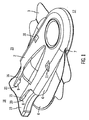
図1で示したように、針ガード17の一実施形態は、挿入デバイス18にぴったり嵌る幅広の側面形状の本体2を備える。針ガード17は、挿入デバイス18の針1上で摺動することができる開口部7を含む。係止機構は、本体2内のアンダーカット部10及び11、並びに本体2の後側から延びるフィンガ突起部8及び9を有するフィンガ15及び16を備えることができる。針ハブ19が針ガード17で覆われた場合に、係止を係合することができる。係止を一時的又は永久に行うことができる。薄く幅広い形状の本体2は、便利で扱いやすいものであるが、本体の開口部が針及び挿入デバイスを受けることができる限り、本発明をより厚く、又は細くすることができる。この形状は、挿入デバイス18を取り外し、又は覆うために針ガード17を使用する場合に、針ガード17を保持又は把持しやすくするものである。他の代替実施形態では、本体は、取扱いのために畝が付けられ砂時計又は他の構造を有するなど、代替本体構造を有することができる。本体2は、挿入デバイス18を受けるように構成された本体2内の開口部7を有する内側5(図2を参照)及び外側6を有する。針ガード17を、針ガード17、並びにカニューレハウジング22及び付着された接着パッチ4とライナ3を有する挿入デバイス18を備えるアセンブリ全体23(図2を参照)としてユーザに配達することができる。一部の輸液セットは、カニューレハウジングのベースに付着された接着パッチを含む。接着剤を1つ又は複数片のライナシステムでカバーし、それを患者が除去して接着側を解放することができる。ライナ3は、患者が輸液セットの使用を望むまで、接着剤を無菌状態に保持し、接着剤が剥がれたり、他に付着したりしないように保護する。
As shown in FIG. 1, one embodiment of the
図1、図2、及び図3では、針ガード17の覆われた位置が示されている。挿入デバイス18は本体2の開口部7内に固定される。針ガード17並びに接着パッチ4及びライナ3を有するカニューレハウジング22に連結された挿入デバイス18を備えるアセンブリ全体23をこの方法でユーザに送って、挿入デバイス18の針1が移行中に覆われる安全な配達を行うことができる。挿入デバイス18はこの覆われた位置でカニューレハウジング22に連結され、配達の準備が整う。針ガード17が挿入デバイス18の針ハブ19上に嵌合された場合、針ガードの内側5のアンダーカット部10及び11との相互作用によって針ガード17を固定することができる。針ガード17のアンダーカット部10及び11は、挿入デバイス18の針ハブ19の両側にある対応する突起部13及び14と対合するように構成される。アセンブリ23がユーザに配達される場合などに、突起部13及び14は、この覆われた位置でカニューレハウジング22によって保持され、アンダーカット部10及び11との相互作用を阻止することができる。それによって、使用の準備が整ったときに、挿入デバイス18を針ガード17から取り外すことができるようになる。他の代替実施形態では、キャップ、シールド、又はある種の別個のガードを備えて、突起部をカニューレハウジング以外で保持することができる。こうすると、挿入デバイス及び針ガードをカニューレハウジングなしで共に包装することができる。アンダーカット部との対合を阻止するために、突起部を押さえるキャップを備えることができる。針ガードを使用して、購入者に配達中に、挿入デバイスの針を解放可能に覆うことができる。
1, 2 and 3, the covered position of the
覆われた位置では、フィンガ突起部8及び9は針ハブ19の後端部と対合するように構成される。フィンガ15及び16は、さらに針ハブ19の孔20及び21に対応する。針ガード17のフィンガ15及び16はハブ孔20及び21まで延び、フィンガ15及び16上の突起部8及び9によって対応するハブ孔20及び21と対合する。フィンガ突起部8及び9をハブ孔20及び21から取り外すことによって、フィンガ15及び16を解放することができる。
In the covered position, the
フィンガ突起部8及び9並びにハブ孔20及び21は、覆われた位置を定めるのに有用であり、それによって、針を露出して挿入することが必要になる前に、針ガード17、及びカニューレハウジング22に連結された挿入デバイス18を含むアセンブリ全体23を安全に配達することができる。他の代替実施形態では、フィンガ、フィンガ突起部、及びハブ孔の数を変えることができる。たとえば一代替係止構造は、針ハブの1つのハブ孔と対合する1つの突起部を備えた1つのフィンガを有することができる。さらに、フィンガは、フック、クリップ、又は他の連結部片など、突起部の代替係止構造を使用することができる。
The
図2で示した部分透視図は、挿入デバイス18が針ガード17で覆われる方法をより明瞭に示す図である。付着された接着パッチ4及びライナ3を有するカニューレハウジング22が針ハブ19の突起部13及び14に押さえられているところが示されている。カニューレハウジング22は、突起部13及び14が針ガード17のアンダーカット部10及び11と対合するのを阻止する。フィンガ15及び16の突起部8及び9はハブ孔20及び21と対合し、使用されるまで安全な配達及び取扱いのために、挿入デバイス18を針ガード17内に固定する。針1は針ガード17の本体2で覆われる。
The partial perspective view shown in FIG. 2 shows more clearly how the
図3に針ガード17の側面外面図がアセンブリ全体23の一部として示されている。針ガード17は接着パッチ4及びライナ3を有するカニューレハウジング22に連結された挿入デバイス18を備える。針ガードはフィンガ突起部8及び9によって挿入デバイス18に解放可能に固定される。フィンガ突起部8及び9は針ハブ19の孔20及び21と対合することができる。針1は針先端の溝(図示せず)内に一時的に固定されて、針1との意図せぬ接触が阻止される。
In FIG. 3, a side view of the
覆われた位置の代替実施形態が図4及び図5に示されている。この位置は一時的又は永久的でもよい。針ガードが挿入のために取り外された後、挿入デバイスがカニューレを皮下に配置しやすくする。カニューレハウジング(図示せず)が注入部位で変位された後、針ハブ19がカニューレハウジングから除去され、突起部13及び14が露出される。突起部13及び14並びにアンダーカット部10及び11は、カニューレハウジングなしで針ハブ19が針ガード17に再挿入される場合に、挿入デバイス18と対合しそれを固定するように構成されている。針ハブ19は以下に示す方法で固定される。針ハブ19が針ガード17の開口部7の内部に存在する。この覆われた位置で、フィンガ15及び16がハブ孔20及び21を超えて針ハブ19の後端部まで延びる。この構成で、針ハブ19上の突起部13及び14が針ガード17のアンダーカット部10及び11に固定される。
An alternative embodiment of the covered position is shown in FIGS. This position may be temporary or permanent. After the needle guard has been removed for insertion, the insertion device facilitates placing the cannula subcutaneously. After the cannula housing (not shown) is displaced at the injection site, the
突起部13、14とアンダーカット部10、11との相互作用が、図5の部分透視図により明瞭に示されている。カニューレハウジングが除去されると、針ハブ19上の突起部13及び14が露出される。突起部13及び14は、針ハブ19が針ガード17の本体2内に受けられた場合に、針ガード17のアンダーカット部10及び11内に対合される。突起部13、14とアンダーカット部10、11が対合して、針ハブ19が針ガード17の外に滑るのが防止される。この位置で針ガード17が針1を覆って、廃棄処分中の意図せぬ傷害が防止される。他の代替実施形態では、アンダーカット部及び突起部の数を変えることができる。たとえば、一代替係止機構は、針ハブ上の1つの突起部と対合する針ガードの1つのアンダーカット部を有することができる。さらに、針ガード及び針ハブは、フィンガは、フック、クリップ、又は他の連結部片など、アンダーカット部と突起部の代替係止構造を使用することができる。
The interaction between the
図5で示した代替の覆われた位置では、フィンガ15及び16はハブ孔20及び21を通過して延びることができ、ハブ孔20及び21との相互作用が回避される。一代替実施形態では、針ガードは突起部を有する上部及び底部のフィンガを有することができる。この代替実施形態では、針ガードを締めつけ、上部フィンガ突起部が底部フィンガ突起部と対合するようにして、針ガードを針ハブ上に固定することによって、針ハブの針ガード内部での固定を行うことができる。針ガードを、ポリプロピレンなど、針ガードを可撓性で屈曲可能にするのに適したプラスチック材料から作成することができる。しかし好ましい場合は、針ガードをポリカーボネートなど非可撓性材料で作成することもできる。別法として、針ガードを、ポリエチレン、ポリウレタン、ポリ塩化ビニル、樹脂、重合体、セラミックス、複合材料など、任意の適した可撓性又は非可撓性材料から作成することができる。
In the alternative covered position shown in FIG. 5, the
限定的ではないが、本体及び係止機構、並びに対応する挿入デバイスを備える針ガードの幾つかの他の実施形態を以下に記載する。各実施形態の構造は、針ハブと針ガードの相互作用に焦点をあてるため、針ハブ及び針ガードに関して各実施形態を記載する。記載されないアセンブリは、記載の要素と同じ対合構造を有し、各実施形態と互換性があるものとする。 Several other embodiments of a needle guard comprising, but not limited to, a body and locking mechanism and a corresponding insertion device are described below. Since the structure of each embodiment focuses on the interaction of the needle hub and needle guard, each embodiment is described with respect to the needle hub and needle guard. Assemblies not described shall have the same mating structure as the elements described and be compatible with each embodiment.
図6で示したように、一実施形態では、針ガードは、開口部107の上部124及び底部125に配置された内側の突起部113及び114を有することができる。この代替実施形態では、針ガードは針ハブ(図示せず)上に嵌る。針ガード117の内部での針ハブ(図示せず)の固定を、針ハブ(図示せず)よりも長く大きい針ガードを使用して行うことができる。針ガード117を内側に締めつけることによって、上部突起部113が底部突起部114と対合し、針ガード117が針ハブ上に固定されて、針(図示せず)が覆われる。一代替実施形態では、それぞれ開口部の上部と底部に1組の2つの突起部が存在する。係止機構は一時的又は永久に覆われた位置を保持することができる。
As shown in FIG. 6, in one embodiment, the needle guard can have
図7で示したように、一実施形態では、針ガード217はアセンブリ223の針ハブ219の一側面上に嵌る一部片として構成される。針ガード217を挿入デバイス218から持ち上げることによって、針ガード217を取り外すことができる。針先端の溝212が針ガード217の一端に配置され、針ガード217が針ハブ219に取り付けられた場合に、その針先端の溝212で針先端201Aが保持される。針ガード217は、外側に延びて針ハブ219の対応するハブ孔220及び221と対合する突起部213及び214を備える。針ガード217を針ハブ219上にスナップ止めして、針201を覆うことができる。この位置は一時的又は永久的でもよい。針201の先端201Aは、針ガード217が針ハブ219に連結された場合に、針先端の溝212の内部に保持される。
As shown in FIG. 7, in one embodiment, the
図8で示したように、一実施形態では、針ガード317は、針ハブ319の後端部で挿入デバイス318に取り付けられる長く細い構造である。針ガード317は他方の端部に針301が保持される針先端の溝312を含む。針ガード317はアーム324を備えることができ、アーム324は針ハブ319の後端部に配置された後部ハブ孔325内に延びて対合される。針ガード317は針ハブ319のハブ孔320及び321と対合する突起部(図示せず)を有することもできる。接合部分326は針ガード317上にアーム324の下方かつ突起部の上方に配置される。接合部分326は、針ガード317をハブ孔320及び321から分離させるために針ガード317を屈曲し、針ガード317を針先端301Aから離れるように屈曲して取り外すことができるようにする可撓性の高い領域である。針301を覆うには、アーム324及び/又は任意選択の突起部(図示せず)を対応するハブ孔320及び321内に再挿入して、針先端301Aが針先端の溝312内に保持されるようにする。針のカバーを一時的又は永久に行うことができる。
As shown in FIG. 8, in one embodiment, the
図9で示したように、一実施形態では、針ガード417は、針ハブ419の後端部で挿入デバイス418に取り付けられる構造である。針ガード417は一端にタブが付けられ、針先端の溝412を含む。タブ426及び427は共に折りたたむことができる材料の薄い幅広のストリップである。1つのタブは突起部413を有することができ、突起部413は第2のタブの対応する孔414内にスナップ止めされ、タブ426及び427が共に固定される。針ガード417は他方の端部にアーム424を備えることができ、アーム424は針ハブ419の後端部に配置された後部ハブ孔425内に延びて対合される。挿入デバイス418及び針ガード417をアセンブリ全体423として受けることができる。挿入前に、タブ付の端部を下方に曲げ、アーム424を後部ハブ孔425から取り外すことによって、針ガード417が針ハブ419から取り外される。針ガード417のアーム424を後部ハブ孔425に挿入し、タブ付き端部を上方に旋回することによって、針ガード417を針ハブ419上に再配置することができる。針ハブ419及び針ガード417が共に取り付けられた後、挿入デバイス418の針401は針先端の溝412内に配置される。この位置でタブ426及び427を上方に折りたたみ、共にスナップ止めして、針先端401Aを針ガード417内に固定することができる。この位置は一時的又は永久的でもよい。針ガード417は、ハブ孔420及び421と対合する追加の突起部(図示せず)を有して、針先端401Aが針先端の溝412内にさらにしっかり固定されるようにすることができる。
As shown in FIG. 9, in one embodiment, the
図10で示したように、一実施形態では、針ガード517は4つの側面524、525、526、及び527を有する対称構造であり、2つの側面524及び525から入ることができる2つの空洞511及び512を含む。空洞511及び512を持たない針ガード517の側面526に針ポート528が存在する。挿入デバイス518の針501を針ポート528内に挿入して、針先端501Aが露出しないようにすることができる。針ガード517及び挿入デバイス518をアセンブリ全体523として受けることができる。この構成では、針501は針ガード517の側面526の針ポート528内に保持される。針ガード517は摩擦によって針501に取り付けられたままになされる。針501は挿入前に針ポート528から引き抜かれる。取り外した後、針ガード517を回転して、ユーザが針501を2つの側面524及び525のいずれかを通して空洞511及び512のいずれかに再挿入することができる。針501が空洞511及び512のうちの1つの中に完全に存在する場合、空洞511及び512の内部の凹部が針ハブ519の対応する留め部と対合する。空洞511内の移動止め513及び514並びに対応する留め部520及び521が図示されている。この位置は一時的でも永久的でもよく、この位置で針501が針ガード517内に固定される。一代替実施形態では、針ガードは4つの側面全てに針ポートを含むことができる。
As shown in FIG. 10, in one embodiment, the
上記は本発明の特定の実施形態を参照したものであるが、理解されるように、本発明の精神から逸脱することなく、多くの変更を加えることができる。添付の特許請求の範囲はこうした変更を本発明の真の範囲及び精神に包含するものである。 Although the foregoing refers to particular embodiments of the invention, it will be understood that many changes can be made without departing from the spirit of the invention. The appended claims are intended to cover such modifications within the true scope and spirit of the present invention.
したがって、現在開示された実施形態はあらゆる点で例示であって限定的ではなく、本発明の範囲は前述の記載ではなく添付の特許請求の範囲によって示されたものである。特許請求の範囲と均等の目的及び範囲内に含まれる変更は全てその中に包含されるものとする。 Accordingly, the presently disclosed embodiments are illustrative in all respects and not restrictive, and the scope of the invention is indicated by the appended claims rather than the foregoing description. All changes that come within the scope and purpose of the claims are intended to be embraced therein.
1、201、301、401、501 針
201A、301A、401A、501A 針先端
2 本体
3 ライナ
4 接着パッチ
5 内側
6 外側
7 開口部
8、9 フィンガ突起部
10、11 アンダーカット部
13、14 突起部
15、16 フィンガ
17、117、217、317、417、517 針ガード
18、218、318、418、518 挿入デバイス
19、219、319、419、519 針ハブ
20、21、220、221、320、321、420、421 ハブ孔
22 カニューレハウジング
23、223、423、523 アセンブリ全体
107 開口部
113、114、213、214、413 突起部
124 頂部
125 底部
212、312、412 針先端の溝
324、424 アーム
325、425 後部ハブ孔
326 接合部分
414 孔
426、427 タブ
511、512 空洞
513、514 移動止め
520、521 留め部
524、525、526、527 側面
528 針ポート
1, 201, 301, 401, 501
Claims (35)
前記針ハブに取外し可能に取り付けられたカニューレハウジングと、
前記針ハブの前記針を覆うように構成された針ガードであって、前記針ハブを受けるように構成された開口部、及び、前記針が該針ガードで覆われた場合に前記挿入デバイスを該針ガード内で固定するように構成された係止部を備える針ガードと、
含んでなることを特徴とする挿入セット。 An insertion device comprising a needle hub and a needle attached to the needle hub;
A cannula housing removably attached to the needle hub;
A needle guard configured to cover the needle of the needle hub, the opening configured to receive the needle hub; and the insertion device when the needle is covered with the needle guard. A needle guard comprising a locking portion configured to be secured within the needle guard;
An insertion set characterized by comprising.
前記挿入デバイスを受けるように構成された開口部、及び、前記針が該針ガードで覆われた場合に前記挿入デバイスを該針ガード内で固定するように構成された係止部を含んでなることを特徴とする針ガード。 A needle guard configured to cover the needle of the insertion device,
An opening configured to receive the insertion device, and a locking portion configured to secure the insertion device within the needle guard when the needle is covered by the needle guard. Needle guard characterized by that.
前記挿入デバイスの前記針を覆うように構成された針ガードであって、前記挿入デバイスを受けるように構成された開口部、及び、前記針が該針ガードで覆われた際に前記挿入デバイスを該針ガード内で固定するように構成された係止部を含む針ガードと、
を含んでなることを特徴とする挿入セット。 An insertion device comprising a hub and a needle attached to the hub;
A needle guard configured to cover the needle of the insertion device, the opening configured to receive the insertion device; and the insertion device when the needle is covered by the needle guard. A needle guard including a locking portion configured to be secured within the needle guard;
An insertion set characterized by comprising.
前記針を前記針ガードで覆うステップと、
前記挿入デバイスを前記針ガードの内部で固定し、前記針を前記針ガードで覆うステップと、
を含んでなることを特徴とする挿入針を覆う方法。 Inserting an insertion device into a needle guard, comprising: an insertion device comprising a needle and a hub when the needle is covered with an opening configured to receive the insertion device and the needle guard; Inserting the insertion device into a needle guard including a locking portion configured to secure the insertion device within the needle guard;
Covering the needle with the needle guard;
Fixing the insertion device inside the needle guard and covering the needle with the needle guard;
A method of covering an insertion needle, comprising:
Applications Claiming Priority (2)
| Application Number | Priority Date | Filing Date | Title |
|---|---|---|---|
| US11/058,074 US20060184104A1 (en) | 2005-02-15 | 2005-02-15 | Needle guard |
| PCT/US2006/000972 WO2006088575A1 (en) | 2005-02-15 | 2006-01-12 | Needle guard |
Publications (1)
| Publication Number | Publication Date |
|---|---|
| JP2008529657A true JP2008529657A (en) | 2008-08-07 |
Family
ID=36354107
Family Applications (1)
| Application Number | Title | Priority Date | Filing Date |
|---|---|---|---|
| JP2007555099A Pending JP2008529657A (en) | 2005-02-15 | 2006-01-12 | Needle guard |
Country Status (5)
| Country | Link |
|---|---|
| US (1) | US20060184104A1 (en) |
| EP (1) | EP1848477A1 (en) |
| JP (1) | JP2008529657A (en) |
| CA (1) | CA2596849A1 (en) |
| WO (1) | WO2006088575A1 (en) |
Cited By (1)
| Publication number | Priority date | Publication date | Assignee | Title |
|---|---|---|---|---|
| JP2022510688A (en) * | 2018-12-07 | 2022-01-27 | ベクトン・ディキンソン・アンド・カンパニー | Injection-molded cannula and its manufacturing method |
Families Citing this family (39)
| Publication number | Priority date | Publication date | Assignee | Title |
|---|---|---|---|---|
| US7648494B2 (en) | 2004-03-26 | 2010-01-19 | Unomedical A/S | Infusion set and injector device for infusion set |
| US8062250B2 (en) | 2004-08-10 | 2011-11-22 | Unomedical A/S | Cannula device |
| US7985199B2 (en) * | 2005-03-17 | 2011-07-26 | Unomedical A/S | Gateway system |
| PT1762259E (en) | 2005-09-12 | 2010-12-10 | Unomedical As | Inserter for an infusion set with a first and second spring units |
| US8475408B2 (en) | 2005-11-08 | 2013-07-02 | Asante Solutions, Inc. | Infusion pump system |
| EP2077128B1 (en) | 2005-12-23 | 2010-12-22 | Unomedical A/S | Injection Device |
| US8657788B2 (en) | 2006-02-07 | 2014-02-25 | Tecpharma Licensing Ag | Infusion set |
| AU2007219546B8 (en) | 2006-02-28 | 2012-07-05 | Unomedical A/S | Inserter for infusion part and infusion part provided with needle protector |
| EP2023818A2 (en) | 2006-06-07 | 2009-02-18 | Unomedical A/S | Inserter for transcutaneous sensor |
| AU2007256563B2 (en) | 2006-06-09 | 2012-09-27 | Unomedical A/S | Mounting pad |
| RU2443436C2 (en) | 2006-08-02 | 2012-02-27 | Уномедикал А/С | Cannula and delivery device |
| EP1917990A1 (en) | 2006-10-31 | 2008-05-07 | Unomedical A/S | Infusion set |
| MX2009013207A (en) | 2007-06-20 | 2010-01-25 | Unomedical As | A catheter and a method and an apparatus for making such catheter. |
| RU2010103450A (en) | 2007-07-03 | 2011-08-10 | Уномедикал А/С (Dk) | INTRODUCTION DEVICE WITH BISTABLE EQUILIBRIUM STATES |
| GB2445437B (en) * | 2007-07-06 | 2008-11-26 | Applied Medical Technology Ltd | Cannula insertion device |
| DK2173410T3 (en) | 2007-07-10 | 2011-06-06 | Unomedical As | Two-spring inserts |
| WO2009010396A1 (en) | 2007-07-18 | 2009-01-22 | Unomedical A/S | Insertion device with pivoting action |
| RU2010137844A (en) | 2008-02-13 | 2012-03-20 | Уномедикал А/С (Dk) | SEAL BETWEEN THE CANULE PART AND BY PASSING A FUEL |
| AU2009216703A1 (en) | 2008-02-20 | 2009-08-27 | Unomedical A/S | Insertion device with horizontally moving part |
| US7959598B2 (en) | 2008-08-20 | 2011-06-14 | Asante Solutions, Inc. | Infusion pump systems and methods |
| RU2011130565A (en) | 2008-12-22 | 2013-01-27 | Уномедикал А/С | MEDICAL DEVICE CONTAINING ADHESIVE GASKET |
| WO2010095152A1 (en) * | 2009-02-18 | 2010-08-26 | Mario Gargani | Safety device for disposable sanitary hollow needles and cutters |
| BR112012002050A2 (en) | 2009-07-30 | 2016-05-17 | Unomedical As | inserter device with part of horizontal movement. |
| AU2010280713A1 (en) | 2009-08-07 | 2012-02-02 | Unomedical A/S | Delivery device with sensor and one or more cannulas |
| BR112012024635A2 (en) | 2010-03-30 | 2017-08-08 | Unomedical As | medical device |
| WO2011157638A1 (en) * | 2010-06-18 | 2011-12-22 | F. Hoffmann-La Roche Ag | Infusion site interfaces and insertion devices for infusion site interfaces |
| EP2433663A1 (en) | 2010-09-27 | 2012-03-28 | Unomedical A/S | Insertion system |
| EP2436412A1 (en) | 2010-10-04 | 2012-04-04 | Unomedical A/S | A sprinkler cannula |
| EP2763723B1 (en) | 2011-10-05 | 2016-04-13 | Unomedical A/S | Inserter for simultaneous insertion of multiple transcutaneous parts |
| EP2583715A1 (en) | 2011-10-19 | 2013-04-24 | Unomedical A/S | Infusion tube system and method for manufacture |
| US9440051B2 (en) | 2011-10-27 | 2016-09-13 | Unomedical A/S | Inserter for a multiplicity of subcutaneous parts |
| US9782538B2 (en) | 2012-09-27 | 2017-10-10 | Becton, Dickinson And Company | Angled inserter for drug infusion |
| US10080839B2 (en) | 2013-03-14 | 2018-09-25 | Becton, Dickinson And Company | Angled inserter for drug infusion |
| US9821113B2 (en) | 2013-03-15 | 2017-11-21 | Becton, Dickinson And Company | Automatic angled infusion set assembly |
| US9561324B2 (en) | 2013-07-19 | 2017-02-07 | Bigfoot Biomedical, Inc. | Infusion pump system and method |
| US10569015B2 (en) | 2013-12-02 | 2020-02-25 | Bigfoot Biomedical, Inc. | Infusion pump system and method |
| US9878097B2 (en) | 2015-04-29 | 2018-01-30 | Bigfoot Biomedical, Inc. | Operating an infusion pump system |
| AU2016385454B2 (en) | 2016-01-05 | 2021-12-16 | Bigfoot Biomedical, Inc. | Operating multi-modal medicine delivery systems |
| CN116983507A (en) | 2019-02-22 | 2023-11-03 | 德卡产品有限公司 | Infusion set and insert assembly systems and methods |
Family Cites Families (88)
| Publication number | Priority date | Publication date | Assignee | Title |
|---|---|---|---|---|
| FR2444064A1 (en) * | 1978-12-15 | 1980-07-11 | Sodip Sa | MIXTURE OF VINYL CHLORIDE POLYMER AND POLYETHERURETHANE WITH A TERTIARY AND / OR AMMONIUM AMINE GROUP, IN PARTICULAR FOR A CONFORMED OBJECT FOR MEDICAL USE |
| US4494950A (en) * | 1982-01-19 | 1985-01-22 | The Johns Hopkins University | Plural module medication delivery system |
| US4678408A (en) * | 1984-01-06 | 1987-07-07 | Pacesetter Infusion, Ltd. | Solenoid drive apparatus for an external infusion pump |
| US4685903A (en) * | 1984-01-06 | 1987-08-11 | Pacesetter Infusion, Ltd. | External infusion pump apparatus |
| US4562751A (en) * | 1984-01-06 | 1986-01-07 | Nason Clyde K | Solenoid drive apparatus for an external infusion pump |
| CA1254091A (en) * | 1984-09-28 | 1989-05-16 | Vladimir Feingold | Implantable medication infusion system |
| US4671288A (en) * | 1985-06-13 | 1987-06-09 | The Regents Of The University Of California | Electrochemical cell sensor for continuous short-term use in tissues and blood |
| US4755173A (en) * | 1986-02-25 | 1988-07-05 | Pacesetter Infusion, Ltd. | Soft cannula subcutaneous injection set |
| US4723947A (en) * | 1986-04-09 | 1988-02-09 | Pacesetter Infusion, Ltd. | Insulin compatible infusion set |
| US4731726A (en) * | 1986-05-19 | 1988-03-15 | Healthware Corporation | Patient-operated glucose monitor and diabetes management system |
| US5360404A (en) * | 1988-12-14 | 1994-11-01 | Inviro Medical Devices Ltd. | Needle guard and needle assembly for syringe |
| US5320725A (en) * | 1989-08-02 | 1994-06-14 | E. Heller & Company | Electrode and method for the detection of hydrogen peroxide |
| US5101814A (en) * | 1989-08-11 | 1992-04-07 | Palti Yoram Prof | System for monitoring and controlling blood glucose |
| US5108819A (en) * | 1990-02-14 | 1992-04-28 | Eli Lilly And Company | Thin film electrical component |
| US5080653A (en) * | 1990-04-16 | 1992-01-14 | Pacesetter Infusion, Ltd. | Infusion pump with dual position syringe locator |
| US5097122A (en) * | 1990-04-16 | 1992-03-17 | Pacesetter Infusion, Ltd. | Medication infusion system having optical motion sensor to detect drive mechanism malfunction |
| US5593852A (en) * | 1993-12-02 | 1997-01-14 | Heller; Adam | Subcutaneous glucose electrode |
| US5322063A (en) * | 1991-10-04 | 1994-06-21 | Eli Lilly And Company | Hydrophilic polyurethane membranes for electrochemical glucose sensors |
| US5284140A (en) * | 1992-02-11 | 1994-02-08 | Eli Lilly And Company | Acrylic copolymer membranes for biosensors |
| ZA938555B (en) * | 1992-11-23 | 1994-08-02 | Lilly Co Eli | Technique to improve the performance of electrochemical sensors |
| US5545143A (en) * | 1993-01-21 | 1996-08-13 | T. S. I. Medical | Device for subcutaneous medication delivery |
| US5299571A (en) * | 1993-01-22 | 1994-04-05 | Eli Lilly And Company | Apparatus and method for implantation of sensors |
| DK25793A (en) * | 1993-03-09 | 1994-09-10 | Pharma Plast Int As | Infusion set for intermittent or continuous administration of a therapeutic agent |
| US5497772A (en) * | 1993-11-19 | 1996-03-12 | Alfred E. Mann Foundation For Scientific Research | Glucose monitoring system |
| US5791344A (en) * | 1993-11-19 | 1998-08-11 | Alfred E. Mann Foundation For Scientific Research | Patient monitoring system |
| US5543326A (en) * | 1994-03-04 | 1996-08-06 | Heller; Adam | Biosensor including chemically modified enzymes |
| US5391250A (en) * | 1994-03-15 | 1995-02-21 | Minimed Inc. | Method of fabricating thin film sensors |
| US5390671A (en) * | 1994-03-15 | 1995-02-21 | Minimed Inc. | Transcutaneous sensor insertion set |
| US5482473A (en) * | 1994-05-09 | 1996-01-09 | Minimed Inc. | Flex circuit connector |
| US5545152A (en) * | 1994-10-28 | 1996-08-13 | Minimed Inc. | Quick-connect coupling for a medication infusion system |
| GB9501218D0 (en) * | 1995-01-21 | 1995-03-15 | Boc Group Plc | Medical devices |
| US5665065A (en) * | 1995-05-26 | 1997-09-09 | Minimed Inc. | Medication infusion device with blood glucose data input |
| US5750926A (en) * | 1995-08-16 | 1998-05-12 | Alfred E. Mann Foundation For Scientific Research | Hermetically sealed electrical feedthrough for use with implantable electronic devices |
| US6689265B2 (en) * | 1995-10-11 | 2004-02-10 | Therasense, Inc. | Electrochemical analyte sensors using thermostable soybean peroxidase |
| US5665222A (en) * | 1995-10-11 | 1997-09-09 | E. Heller & Company | Soybean peroxidase electrochemical sensor |
| US6043437A (en) * | 1996-12-20 | 2000-03-28 | Alfred E. Mann Foundation | Alumina insulation for coating implantable components and other microminiature devices |
| JP3394262B2 (en) * | 1997-02-06 | 2003-04-07 | セラセンス、インク. | Small volume in vitro analyte sensor |
| US5779665A (en) * | 1997-05-08 | 1998-07-14 | Minimed Inc. | Transdermal introducer assembly |
| US5954643A (en) * | 1997-06-09 | 1999-09-21 | Minimid Inc. | Insertion set for a transcutaneous sensor |
| US5917346A (en) * | 1997-09-12 | 1999-06-29 | Alfred E. Mann Foundation | Low power current to frequency converter circuit for use in implantable sensors |
| US6259937B1 (en) * | 1997-09-12 | 2001-07-10 | Alfred E. Mann Foundation | Implantable substrate sensor |
| US6071391A (en) * | 1997-09-12 | 2000-06-06 | Nok Corporation | Enzyme electrode structure |
| US6081736A (en) * | 1997-10-20 | 2000-06-27 | Alfred E. Mann Foundation | Implantable enzyme-based monitoring systems adapted for long term use |
| US6088608A (en) * | 1997-10-20 | 2000-07-11 | Alfred E. Mann Foundation | Electrochemical sensor and integrity tests therefor |
| US6119028A (en) * | 1997-10-20 | 2000-09-12 | Alfred E. Mann Foundation | Implantable enzyme-based monitoring systems having improved longevity due to improved exterior surfaces |
| US6579690B1 (en) * | 1997-12-05 | 2003-06-17 | Therasense, Inc. | Blood analyte monitoring through subcutaneous measurement |
| US6056718A (en) * | 1998-03-04 | 2000-05-02 | Minimed Inc. | Medication infusion set |
| US6134461A (en) * | 1998-03-04 | 2000-10-17 | E. Heller & Company | Electrochemical analyte |
| US6103033A (en) * | 1998-03-04 | 2000-08-15 | Therasense, Inc. | Process for producing an electrochemical biosensor |
| AU3006199A (en) * | 1998-03-16 | 1999-10-11 | Medtronic, Inc. | Hemostatic system and components for extracorporeal circuit |
| US5904708A (en) * | 1998-03-19 | 1999-05-18 | Medtronic, Inc. | System and method for deriving relative physiologic signals |
| US6123690A (en) * | 1998-03-20 | 2000-09-26 | Maersk Medical A/S | Subcutaneous infusion device |
| US6086575A (en) * | 1998-03-20 | 2000-07-11 | Maersk Medical A/S | Subcutaneous infusion device |
| US6175752B1 (en) * | 1998-04-30 | 2001-01-16 | Therasense, Inc. | Analyte monitoring device and methods of use |
| US6294281B1 (en) * | 1998-06-17 | 2001-09-25 | Therasense, Inc. | Biological fuel cell and method |
| US6736797B1 (en) * | 1998-06-19 | 2004-05-18 | Unomedical A/S | Subcutaneous infusion set |
| US6355021B1 (en) * | 1998-07-14 | 2002-03-12 | Maersk Medical A/S | Medical puncturing device |
| US5891098A (en) * | 1998-08-17 | 1999-04-06 | Huang; Robert | Safety intravenous catheter |
| US6554798B1 (en) * | 1998-08-18 | 2003-04-29 | Medtronic Minimed, Inc. | External infusion device with remote programming, bolus estimator and/or vibration alarm capabilities |
| US6558320B1 (en) * | 2000-01-20 | 2003-05-06 | Medtronic Minimed, Inc. | Handheld personal data assistant (PDA) with a medical device and method of using the same |
| US6074371A (en) * | 1998-09-10 | 2000-06-13 | Magnolia Medical, Llc | Blunt injection needle for a pen-type injector |
| US6591125B1 (en) * | 2000-06-27 | 2003-07-08 | Therasense, Inc. | Small volume in vitro analyte sensor with diffusible or non-leachable redox mediator |
| US6338790B1 (en) * | 1998-10-08 | 2002-01-15 | Therasense, Inc. | Small volume in vitro analyte sensor with diffusible or non-leachable redox mediator |
| US6235005B1 (en) * | 1998-12-28 | 2001-05-22 | Ethicon, Inc. | Positive engagement-disengagement catheter sleeve |
| US6560741B1 (en) * | 1999-02-24 | 2003-05-06 | Datastrip (Iom) Limited | Two-dimensional printed code for storing biometric information and integrated off-line apparatus for reading same |
| US6117110A (en) * | 1999-03-26 | 2000-09-12 | Radmand; Reza | Catheter needle safety device and method of using same |
| EP2322645A1 (en) * | 1999-06-18 | 2011-05-18 | Abbott Diabetes Care Inc. | Mass transport limited in vivo analyte sensor |
| US6804558B2 (en) * | 1999-07-07 | 2004-10-12 | Medtronic, Inc. | System and method of communicating between an implantable medical device and a remote computer system or health care provider |
| US6616819B1 (en) * | 1999-11-04 | 2003-09-09 | Therasense, Inc. | Small volume in vitro analyte sensor and methods |
| WO2001036660A2 (en) * | 1999-11-15 | 2001-05-25 | Therasense, Inc. | Transition metal complexes attached to a polymer via a flexible chain |
| US6623501B2 (en) * | 2000-04-05 | 2003-09-23 | Therasense, Inc. | Reusable ceramic skin-piercing device |
| WO2001088524A1 (en) * | 2000-05-12 | 2001-11-22 | Therasense, Inc. | Electrodes with multilayer membranes and methods of using and making the electrodes |
| US6685674B2 (en) * | 2001-03-04 | 2004-02-03 | Sterling Medivations, Inc. | Infusion hub assembly and fluid line disconnect system |
| WO2002078512A2 (en) * | 2001-04-02 | 2002-10-10 | Therasense, Inc. | Blood glucose tracking apparatus and methods |
| US6676816B2 (en) * | 2001-05-11 | 2004-01-13 | Therasense, Inc. | Transition metal complexes with (pyridyl)imidazole ligands and sensors using said complexes |
| US6932894B2 (en) * | 2001-05-15 | 2005-08-23 | Therasense, Inc. | Biosensor membranes composed of polymers containing heterocyclic nitrogens |
| US7025760B2 (en) * | 2001-09-07 | 2006-04-11 | Medtronic Minimed, Inc. | Method and system for non-vascular sensor implantation |
| US7052591B2 (en) * | 2001-09-21 | 2006-05-30 | Therasense, Inc. | Electrodeposition of redox polymers and co-electrodeposition of enzymes by coordinative crosslinking |
| US20030061232A1 (en) * | 2001-09-21 | 2003-03-27 | Dun & Bradstreet Inc. | Method and system for processing business data |
| US20030061234A1 (en) * | 2001-09-25 | 2003-03-27 | Ali Mohammed Zamshed | Application location register routing |
| US7060053B2 (en) * | 2002-02-28 | 2006-06-13 | Medikit Co., Ltd. | Safety indwelling syringe |
| US7162289B2 (en) * | 2002-09-27 | 2007-01-09 | Medtronic Minimed, Inc. | Method and apparatus for enhancing the integrity of an implantable sensor device |
| US7736309B2 (en) * | 2002-09-27 | 2010-06-15 | Medtronic Minimed, Inc. | Implantable sensor method and system |
| EP2386758A1 (en) * | 2002-10-09 | 2011-11-16 | Abbott Diabetes Care Inc. | A method of pumping a predetermined dose of a medical fluid |
| US20040074785A1 (en) * | 2002-10-18 | 2004-04-22 | Holker James D. | Analyte sensors and methods for making them |
| US6931328B2 (en) * | 2002-11-08 | 2005-08-16 | Optiscan Biomedical Corp. | Analyte detection system with software download capabilities |
| DE602004018699D1 (en) * | 2003-03-20 | 2009-02-12 | Nipro Corp | Protective cap for needle with wings |
| US7201977B2 (en) * | 2004-03-23 | 2007-04-10 | Seagate Technology Llc | Anti-ferromagnetically coupled granular-continuous magnetic recording media |
-
2005
- 2005-02-15 US US11/058,074 patent/US20060184104A1/en not_active Abandoned
-
2006
- 2006-01-12 WO PCT/US2006/000972 patent/WO2006088575A1/en active Application Filing
- 2006-01-12 EP EP06718087A patent/EP1848477A1/en not_active Withdrawn
- 2006-01-12 CA CA002596849A patent/CA2596849A1/en not_active Abandoned
- 2006-01-12 JP JP2007555099A patent/JP2008529657A/en active Pending
Cited By (1)
| Publication number | Priority date | Publication date | Assignee | Title |
|---|---|---|---|---|
| JP2022510688A (en) * | 2018-12-07 | 2022-01-27 | ベクトン・ディキンソン・アンド・カンパニー | Injection-molded cannula and its manufacturing method |
Also Published As
| Publication number | Publication date |
|---|---|
| WO2006088575A1 (en) | 2006-08-24 |
| US20060184104A1 (en) | 2006-08-17 |
| EP1848477A1 (en) | 2007-10-31 |
| CA2596849A1 (en) | 2006-08-24 |
Similar Documents
| Publication | Publication Date | Title |
|---|---|---|
| JP2008529657A (en) | Needle guard | |
| JP4809371B2 (en) | Insertion device | |
| CA2585901C (en) | Multi-position infusion set device and process | |
| EP1474199B1 (en) | Infusion device with needle shield | |
| JP5073739B2 (en) | Venous catheter assembly with ergonomic needle grip | |
| US6921388B2 (en) | Needle assembly | |
| US8961476B2 (en) | Sharps protector device for protecting a user from a sharp tip of a medical needle | |
| JP5686897B2 (en) | Passive shielding needle assembly with skin sensor | |
| JP2005521537A (en) | Medical needle safety shield | |
| JP2006061379A (en) | Curved needle with wing | |
| ES2367987T3 (en) | SAFETY NEEDLE ASSEMBLY. | |
| US20050124938A1 (en) | One-shot needle safety cover | |
| JPH04297276A (en) | Catheter with needle protector | |
| JP4544943B2 (en) | Curved needle with wings | |
| EP3976141A1 (en) | Needle cover and safety needle assembly including same | |
| JP4913723B2 (en) | Injector set for injection set | |
| JP6511863B2 (en) | Indwelling needle assembly | |
| JP2002065848A (en) | Protector of needle for injecting medicine |