JP6138027B2 - Trolley equipment - Google Patents
Trolley equipment Download PDFInfo
- Publication number
- JP6138027B2 JP6138027B2 JP2013235031A JP2013235031A JP6138027B2 JP 6138027 B2 JP6138027 B2 JP 6138027B2 JP 2013235031 A JP2013235031 A JP 2013235031A JP 2013235031 A JP2013235031 A JP 2013235031A JP 6138027 B2 JP6138027 B2 JP 6138027B2
- Authority
- JP
- Japan
- Prior art keywords
- power consumption
- value
- unit
- endoscope
- power
- Prior art date
- Legal status (The legal status is an assumption and is not a legal conclusion. Google has not performed a legal analysis and makes no representation as to the accuracy of the status listed.)
- Active
Links
Images


Description
本発明は、内視鏡を用いて手術等を行う際に用いられる内視鏡用周辺機器を搭載するトロリー装置に関する。 The present invention relates to a trolley device equipped with an endoscope peripheral device used when performing an operation or the like using an endoscope.
近年、内視鏡は医療分野等において広く用いられるようになっている。また、内視鏡を用いて手術等を行う場合には、内視鏡と共に用いられる内視鏡用周辺機器としての光源装置、プロセッサ(又はカメラコントロールユニット)、モニター、高周波電流により処置を行う高周波焼灼装置(又は電気メス装置)等が用いられる。
これら複数の内視鏡用周辺機器は、手術等を円滑に行い易いように移動可能なトロリー装置に搭載され、トロリー装置は患者が横たわるベッドの付近に配置される。
また、トロリー装置には、当該トロリー装置に搭載された内視鏡用周辺機器に対して、商用電源と絶縁して電源を供給する絶縁トランスを搭載した電源回路を備えている。
例えば従来例としての特開2001−120570号公報は、壁コンセントの電源をトロリー装置の絶縁トランスを介して、トロリー装置に搭載された複数の内視鏡用周辺機器に供給し、壁コンセント等の電源手段の許容電流容量の範囲に入るように、複数の内視鏡用周辺機器の内、使用する内視鏡用周辺機器の数を制限する電源供給制限手段と、使用中の内視鏡用周辺機器への供給電流を絶縁トランスの1次側で検出する電源電流検出手段と、を備え、トロリー装置に過剰な数の内視鏡用周辺機器が接続されるのを防止する内視鏡システムを開示している。
In recent years, endoscopes have been widely used in the medical field and the like. Further, when performing an operation or the like using an endoscope, a light source device, a processor (or a camera control unit), a monitor, and a high frequency for performing treatment with a high frequency current as an endoscope peripheral device used together with the endoscope. A cautery device (or an electric knife device) or the like is used.
The plurality of peripheral devices for endoscope are mounted on a trolley device that can be moved so that surgery and the like can be performed smoothly, and the trolley device is disposed in the vicinity of the bed on which the patient lies.
Further, the trolley device is provided with a power supply circuit equipped with an insulation transformer that insulates from a commercial power supply and supplies power to the endoscope peripheral device mounted on the trolley device.
For example, Japanese Patent Laid-Open No. 2001-120570 as a conventional example supplies wall outlet power to a plurality of endoscope peripheral devices mounted on a trolley device via an insulating transformer of the trolley device, Power supply limiting means for limiting the number of endoscope peripheral devices to be used among a plurality of endoscope peripheral devices so as to fall within the allowable current capacity range of the power supply means, and for endoscopes in use An endoscope system comprising: a power supply current detecting means for detecting a supply current to the peripheral device on the primary side of the insulating transformer, and preventing an excessive number of endoscope peripheral devices from being connected to the trolley device Is disclosed.
上記公報の従来例は、電源手段の許容電流容量の範囲に入るように、複数の内視鏡用周辺機器の内、使用する内視鏡用周辺機器の数を制限する内容を開示している。各内視鏡用周辺機器の電源電流容量は対比テーブルから算出可能とされるが、電気メス装置のように実際に処置する際の出力設定のパラメータに依存して消費電力値が大きく変化するような内視鏡用周辺機器の場合に対しては、適切に対応出来ない欠点がある。具体的には、ユーザーとしての術者が電気メス装置を用いて実際に処置する際の出力設定のパラメータは、処置対象に依存して、又は術者の手技によって異なり、電気メス装置の仕様(規格)上での最大の出力設定で行うことはまれである。
しかし従来例においては、電気メス装置のように出力設定のパラメータに依存して消費電力値が大きく変化する内視鏡用周辺機器を使用する場合、該内視鏡用周辺機器の仕様(規格)上での最大の消費電力値を用いて、絶縁トランスが供給可能な電源容量以内か否かを判定すると想定される。(仮に、最大の消費電力値を用いていない想定であると、変更前の状態よりも消費電力が増大するようにパラメータを変更すると、電源手段の許容電流容量の範囲を超えてブレーカーが遮断する事態が発生してしまう)。
The conventional example of the above publication discloses a content that limits the number of endoscope peripheral devices to be used among a plurality of endoscope peripheral devices so as to fall within the allowable current capacity range of the power supply means. . The power supply current capacity of each endoscope peripheral device can be calculated from the comparison table, but the power consumption value varies greatly depending on the output setting parameters when actually performing treatment like an electric knife device. In the case of an endoscope peripheral device, there is a drawback that it cannot be appropriately handled. Specifically, the parameter of the output setting when the surgeon as a user actually performs treatment using the electrosurgical device differs depending on the treatment target or depending on the procedure of the surgeon, and the specifications of the electrosurgical device ( It is rare to do this with the maximum output setting.
However, in the conventional example, when using an endoscope peripheral device whose power consumption value varies greatly depending on output setting parameters, such as an electric knife device, specifications (standards) of the endoscope peripheral device are used. It is assumed that the maximum power consumption value above is used to determine whether or not it is within the power supply capacity that can be supplied by the insulation transformer. (Assuming that the maximum power consumption value is not used, if the parameter is changed so that the power consumption increases compared to the state before the change, the breaker will shut off exceeding the allowable current capacity range of the power supply means. Things will happen).
このため、術者が電気メス装置を用いて実際に処置する際に使用する最大の出力設定(のパラメータ)の場合の消費電力を電気メス装置の最大消費電力とするように出力設定を制限するように制御すれば、電気メス装置のような内視鏡用周辺機器における仕様上での最大消費電力値を用いなくても、実質的には支障なく使用できる。
このように従来例においては、実際に使用する場合のパラメータの設定値に対応した消費電力値を用いて制御するようにしていないため、消費電力値を過度に大きく見積もってしまうことになるため、その分だけ、1つのトロリー装置に搭載されている絶縁トランスにより供給可能な電源容量が小さくなってしまい、1つのトロリー装置に搭載されている絶縁トランスにより供給可能な内視鏡用周辺機器の数が小さくなってしまう。
換言すると、パラメータの設定値に依存して消費電力の値が変化する電気メス装置のような内視鏡用周辺機器に対しては、その使用時における消費電力値の最大値を上限の消費電力値に設定し、上限の消費電力値以下となるように制御すれば、1つのトロリー装置に搭載されている絶縁トランス装置により供給可能な電源容量によって、数多くの内視鏡用周辺機器に電源を供給することが可能になる場合があるが、従来例ではそのような制御を行っていなかった。
本発明は上述した点に鑑みてなされたもので、パラメータの設定値に依存して消費電力値が変化する内視鏡用周辺機器に対して、使用時における消費電力値の最大値を上限の消費電力値以下となるようにパラメータの設定範囲を制限することにより、1台で数多くの内視鏡用周辺機器に電源を供給することができるトロリー装置を提供することを目的とする。
For this reason, the output setting is limited so that the power consumption in the case of the maximum output setting (parameters) used when the operator actually performs treatment using the electric knife device is the maximum power consumption of the electric knife device. If controlled in this way, even if the maximum power consumption value in the specification of the peripheral device for endoscope such as an electric knife device is not used, it can be used without any problem.
As described above, in the conventional example, since the control is not performed using the power consumption value corresponding to the set value of the parameter when actually used, the power consumption value is estimated too large. Accordingly, the power supply capacity that can be supplied by the isolation transformer mounted on one trolley device is reduced, and the number of endoscope peripheral devices that can be supplied by the isolation transformer mounted on one trolley device. Will become smaller.
In other words, for endoscope peripheral devices such as an electrosurgical device whose power consumption value changes depending on the parameter setting value, the maximum power consumption value at the time of use is the upper limit power consumption. If the power is set to a value and controlled to be equal to or less than the upper limit power consumption value, power can be supplied to many endoscope peripheral devices by the power supply capacity that can be supplied by the insulation transformer device mounted on one trolley device. Although it may be possible to supply, such control is not performed in the conventional example.
The present invention has been made in view of the above-described points, and for the endoscope peripheral device whose power consumption value changes depending on the parameter setting value, the maximum power consumption value during use is set as the upper limit. An object of the present invention is to provide a trolley device that can supply power to a large number of peripheral devices for an endoscope by limiting the parameter setting range so as to be equal to or lower than the power consumption value.
本発明の一態様に係るトロリー装置は、複数の内視鏡用周辺機器を搭載可能とする搭載部と、商用電源に1次コイル側が接続され、前記1次コイルと絶縁された2次コイルから前記商用電源と絶縁された交流電源を供給する絶縁トランスを備えた絶縁トランス装置と、絶縁トランスの2次コイル側に設けられ、前記複数の内視鏡用周辺機器の電源入力端がそれぞれ接続され、接続された前記電源入力端にそれぞれ前記交流電源を供給する複数の電源出力部と、前記複数の電源出力部に接続された前記複数の内視鏡用周辺機器の機種を判別する接続機種判別部と、前記接続機種判別部による前記機種の判別結果と共に、前記複数の電源出力部に接続された前記複数の内視鏡用周辺機器の各消費電力値、又は前記各消費電力値を算出するための各パラメータを取得する取得部と、前記取得部の取得結果に応じて前記複数の電源出力部に接続された前記複数の内視鏡用周辺機器の前記各消費電力値の合計値を算出する消費電力算出部と、前記絶縁トランスが供給可能とする電源容量値から前記消費電力算出部により算出された前記合計値を減算した差分を計算する計算部と、前記計算部により計算された前記差分が正となる条件を満たすように、少なくとも前記複数の電源出力部に接続された前記複数の内視鏡用周辺機器のうち、前記パラメータの設定値に応じて消費電力値が実質的に変化する、前記接続機種判別によって判別された特定の機種としての特定の内視鏡用周辺機器に対して、前記計算部により計算された前記差分が正となる条件を満たすような前記パラメータの設定値に応じた消費電力値を、前記特定の内視鏡用周辺機器の使用時における上限の消費電力値に設定する上限設定部と、前記特定の内視鏡用周辺機器に対して前記上限の消費電力値のデータを送信することで、少なくとも前記特定の内視鏡用周辺機器を使用中に設定される前記パラメータの設定値が前記上限設定部により設定された前記上限の消費電力値以下の範囲内となるように、前記パラメータの設定値の変化を制限する制御を前記特定の内視鏡用周辺機器に対して行う制御部と、を有する。 A trolley device according to an aspect of the present invention includes a mounting portion that can mount a plurality of peripheral devices for endoscope, and a secondary coil that is connected to a commercial power source and is insulated from the primary coil. An insulation transformer device having an insulation transformer for supplying AC power that is insulated from the commercial power supply, and a secondary coil side of the insulation transformer, each of which is connected to the power input terminals of the plurality of endoscope peripheral devices A plurality of power supply output units for supplying the AC power to the connected power input terminals, and a connected model determination unit for determining a model of the plurality of endoscope peripheral devices connected to the plurality of power supply output units. and parts, with the result of the determination model according to the connection model determination unit, wherein the power consumption value of the plurality of peripheral devices for a plurality of endoscope connected to the power output unit, or to calculate the respective power values each for A power consumption for calculating a total value of the power consumption values of the plurality of peripheral devices for endoscope connected to the plurality of power output units according to the acquisition result of the acquisition unit and the acquisition unit for acquiring parameters A calculation unit that calculates a difference obtained by subtracting the total value calculated by the power consumption calculation unit from a power supply capacity value that can be supplied by the isolation transformer; and the difference calculated by the calculation unit is positive. Among the plurality of endoscope peripheral devices connected to at least the plurality of power output units so as to satisfy the condition to be, the power consumption value substantially changes according to the set value of the parameter , response for a particular endoscope peripheral devices as a specific model that is determined by the connection model determination, the set value of the calculation unit by the calculated the parameters satisfy the condition that the difference is positive and And the power consumption value, wherein the upper limit setting unit which sets the power consumption value of the upper limit at the time of use in particular for an endoscope peripheral device, the upper limit power consumption value of the peripheral equipment the particular endoscope By transmitting the data, at least the set value of the parameter set while using the specific endoscope peripheral device is within the range of the power consumption value of the upper limit set by the upper limit setting unit. And a control unit that performs control for restricting a change in the set value of the parameter for the specific peripheral device for endoscope .
本発明によれば、パラメータの設定値に依存して消費電力値が変化する内視鏡用周辺機器に対しては、使用時における消費電力値を上限の消費電力値以下となるようにパラメータの設定範囲を制限することにより、1台で数多くの内視鏡用周辺機器に電源を供給することができる。 According to the present invention, for an endoscope peripheral device whose power consumption value changes depending on the parameter setting value, the parameter value is set so that the power consumption value during use is less than or equal to the upper limit power consumption value. By limiting the setting range, power can be supplied to a large number of endoscope peripheral devices with a single unit.
以下、図面を参照して本発明の実施形態を説明する。
(第1の実施形態)
図1に示すように内視鏡システム1は、ベッド2に横たわる患者3に対して、本発明の第1の実施形態のトロリー装置4に搭載された内視鏡用周辺機器を用いて、治療のための処置を行う。
この内視鏡システム1は、患者3の例えば腹部内にトラカール5を介して内視鏡6の挿入部7が刺入され、また、高周波の電気エネルギーによる処置を行う処置具としての電気メス8が図示しないトラカールを介して腹部内に刺入される。
また、ベッド2の周辺に配置されるトロリー装置4には、機種(種類)が異なる複数の内視鏡用周辺機器が搭載される。
Hereinafter, embodiments of the present invention will be described with reference to the drawings.
(First embodiment)
As shown in FIG. 1, the
In this
The trolley device 4 arranged around the
このトロリー装置4は、所定数以下となる複数の内視鏡用周辺機器を搭載可能とする搭載部を構成する載置台11を備えたトロリー装置本体12と、このトロリー装置本体12の底部付近に設けられ、内部に絶縁トランス53(図4参照)を内蔵した絶縁トランス装置14とを有すると共に、トロリー装置本体12の底面には、回転自在に設けられ、トロリー装置12を移動し易くするためのキャスタ15が取り付けられている。
箱型のトロリー装置本体12に設けた複数の載置台11には、ビデオプロセッサ21、光源装置22、電気メス電源装置(又は電気メス装置)23、ビデオプリンタ24、気腹装置25が載置され、箱型のトロリー装置本体12の上面には、モニター26が保持アーム27を介して搭載される。このように、トロリー装置本体12には、複数の内視鏡用周辺機器としてのビデオプロセッサ21、光源装置22、電気メス電源装置(又は電気メス装置)23、ビデオプリンタ24、気腹装置25、モニター26が搭載される。
The trolley device 4 includes a trolley device
A
また、 トロリー装置本体12の上面には、トロリー装置4に設けられた表示パネル28が載置されている。
内視鏡6は、ライトガイドケーブル31を介して、光源装置22に接続され、光源装置22により発生した照明光がライトガイドケーブル31を介して内視鏡6に供給され、内視鏡6内部のライトガイド45(図5参照)を経て伝送された照明光は、内視鏡6の挿入部7の先端の照明窓から外部に出射され、腹部内部の患部等の部位を照明する。照明された患部等の部位は、照明窓に隣接して設けた観察窓の図示しない対物レンズにより、撮像素子46(図5参照)の結像面にその光学像が結像され、撮像素子46により光電変換される。撮像素子46は、例えば内視鏡6の後端側から延出した信号ケーブル32を介して信号処理装置としてのビデオプロセッサ21に接続される。
A
The
ビデオプロセッサ21により生成された画像信号(映像信号)はモニター26に出力され、モニター26の表示面には、撮像素子46で撮像した画像が内視鏡画像として表示される。
また、処置具としての電気メス8は、電気メスケーブル33を介して前記電気メスにより処置に利用される高周波電気エネルギーを形成する高周波信号を出力(発生)する電気メス装置23に接続され、電気メス装置23から高周波信号が電気メス8に供給されることにより、術者は電気メス8の先端の例えばバイポーラ電極を処置対象の患部の組織に当接させることにより、当該電極が当接された組織に高密度の高周波信号電流(高周波電流と略記)が流れ、切除する等の処置を行うことができる。
また、電気メス装置23には、フットスイッチ34が接続され、術者はフットスイッチ34を操作して、電気メス装置23から電気メス8に供給される高周波電流のON/OFFを行うことができる。
An image signal (video signal) generated by the
The
In addition, a
またトラカール5は、気腹チューブ36を介して気腹装置25に接続され、気腹指示の操作により、気腹装置25は、気腹用の気体を気腹チューブ36を介してトラカール5側に送気し、腹部内部を気腹用の気体で膨らませ、内視鏡6による観察のための視野を確保すると共に、処置具としての電気メス8による処置をする空間を確保する。
ビデオプリンタ24は、ビデオプロセッサ21の画像信号が入力され、プリントの指示操作がされると、モニター26に表示される内視鏡画像をプリントする。
トロリー装置4を構成し、トロリー装置本体12の底面付近に設けた絶縁トランス装置14は主電源コード37を介して、その末端のプラグ37aが内視鏡システム1が配置された手術室の壁面に設けた壁コンセント(エレクトリカル・アウトレット)38に着脱自在に接続される。そして、壁コンセント38から主電源コード37を介して、絶縁トランス装置14には商用電源(商用交流電源)が供給され、供給された商用電源は、絶縁トランスにより、当該商用電源と絶縁された電源(交流電源)に変換される。
The
The
The
図2は、図1のトロリー装置4をより詳細に示す正面図である。また、図3は、トロリー装置本体12の底面付近に設けた絶縁トランス装置14の背面図を示し、絶縁トランス装置14は、商用電源と絶縁した交流電源を出力する複数の電源出力部を形成する複数の電源出力アウトレット41a〜41fからなる電源出力アウトレット部41を有する。
また、絶縁トランス装置14は、複数の通信コネクタ受け42a〜42fからなる通信コネクタ受け部42を有する。なお、図3においては電源出力アウトレット41a〜41fと通信コネクタ受け42a〜42fの数がそれぞれ6個の場合で示しているが、6個の場合に限定されるものでない。
そして、図4に示すように複数の電源出力アウトレット41a〜41fには、複数の内視鏡用周辺機器としてのビデオプロセッサ21,光源装置22,…,モニター26の電源コード21a,22a,…,26a(簡略化して21a〜26aとも記す)の端部に設けられ、電源入力端を構成する電源プラグ21b,22b,…,26b(簡略化して21b〜26bとも記す)がそれぞれ接続され、また複数の通信コネクタ受け42a〜42fには、図4に示すようにビデオプロセッサ21,光源装置22,…,モニター26の通信コード21c,22c,…,26c(簡略化して21c〜26cとも記す)の端部に設けた通信コネクタ21d,22d,…,26d(簡略化して21d〜26dとも記す)がそれぞれ接続される。
FIG. 2 is a front view showing the trolley device 4 of FIG. 1 in more detail. FIG. 3 is a rear view of the insulating
Further, the insulating
As shown in FIG. 4, the plurality of
複数の通信コネクタ受け42a〜42fは、それぞれ複数の電源出力アウトレット41a〜41fと対応付けて設けられている。従って、例えば電源出力アウトレット41i(i=a〜fのいずれか)に電源プラグJb(J=21〜26)が接続されると、電源プラグJbを有する内視鏡用周辺機器Jの通信コネクタJdが通信コネクタ受け42iに接続されるように設定されている。このため、接続する際の誤接続を防止するために、例えば複数の電源出力アウトレット41a〜41fに対して、第1電源出力アウトレット〜第6電源出力アウトレットを示すための(第1,第2,…,第6等の)序数や数字、文字などを、電源出力アウトレット41iと、(対応する)通信コネクタ受け42iの近傍に記載するようにしても良い。また、図3に示すように電源出力アウトレット部41と通信コネクタ受け部42とを左右に配置しないで、電源出力アウトレット41iに対応する通信コネクタ受けが42iであることをより分かり易くするように、電源出力アウトレット部41と通信コネクタ受け部42とを上下に隣接してそれぞれ1列となるように配置しても良い。
The plurality of
なお、図3に示すように電源出力アウトレット部41の上部には、この電源出力アウトレット部41から絶縁電源トランス14が供給可能とする(最大の)電源容量値が記載されている。図3の場合には、(最大の)電源容量値が1350VAである。なお、電源容量値は、主に絶縁トランス53の仕様によって決定される。
図4は絶縁トランス装置14の構成を示す。なお、図4は、上述したようにそれぞれの電源出力アウトレット41a〜41fに、(複数の内視鏡用周辺機器としての)ビデオプロセッサ21,光源装置22,…,モニター26の電源プラグ21b〜26bがそれぞれ接続された状態で、かつ複数の通信コネクタ受け42a〜42fに、複数の通信コネクタ22d〜26dがそれぞれ接続された状態で絶縁トランス装置14の構成を示している。
絶縁トランス装置14の筐体51内には、途中に上記電源容量値を超える消費電力が発生した場合には遮断するブレーカー52が介挿された主電源コード37の基端が絶縁トランス53の1次巻線53aに接続される。この絶縁トランス53の2次巻線53bの出力端子となる両端子には、当該2次巻線53bに誘起する交流電源の電圧を計測する交流電圧計(単に電圧計と略記)54が接続される。
As shown in FIG. 3, the (maximum) power capacity value that enables the
FIG. 4 shows the configuration of the insulating
In the
この絶縁トランス53の2次巻線53bにおける一方の端子は、それぞれ交流電流を計測する交流電流計(単に電流計と略記)55a〜55fがそれぞれ介挿された状態の電源線56a〜56fにより電源出力アウトレット41a〜41fの一方の電源端子に接続され、2次巻線53bにおける他方の端子は、それぞれ電源線57a〜57fにより電源出力アウトレット41a〜41fの他方の電源端子に接続される。
そして、電源出力アウトレット41a〜41fにそれぞれ接続される電源プラグ21b〜26b及び電源コード21a〜26aを経て、当該電源コード21a〜26aを設けた複数の内視鏡用周辺機器としてのビデオプロセッサ21,光源装置22,…,モニター26に、商用電源から絶縁された交流電源をそれぞれ供給することができるようにしている。
本実施形態においては、電源出力アウトレット41a〜41fにそれぞれ接続される複数の内視鏡用周辺機器に供給される交流電源の消費電力量を共通の電圧計54と、複数の電流計55a〜55fにより、算出(検出)することができるようにしている。
One terminal of the secondary winding 53b of the insulating
Then, the
In the present embodiment, the common voltmeter 54 and the plurality of ammeters 55a to 55f are used for the power consumption of the AC power supplied to the plurality of endoscope peripheral devices connected to the
上記電圧計54及び電流計55a〜55fにより計測(検出)された交流電圧及び交流電流は、筐体51内部の電源監視ユニット61に入力される。
また、複数の内視鏡用周辺機器としてのビデオプロセッサ21,光源装置22,…,モニター26の通信コネクタ21d〜26dがそれぞれ接続される通信コネクタ受け42a〜42fは、筐体51内部の通信部62と接続され、通信部62は各内視鏡用周辺機器と通信を行う。
この通信部62は、例えば中央演算処理装置(CPU)によりそれぞれ構成される電源監視ユニット61及び判別部63と接続されている。判別部63は、通信部62を介して各内視鏡用周辺機器と通信を行い、絶縁トランス装置14における複数の電源出力部を形成する複数の電源出力アウトレット41a〜41fにそれぞれ接続された各内視鏡用周辺機器の機種(種類)を判別する。
つまり、この判別部63は、トロリー装置4の絶縁トランス装置14における複数の電源出力部にそれぞれ接続された接続機器(図4の例ではビデオプロセッサ21,光源装置22,…,モニター26)の機種を判別する接続機種判別部63aの機能を有する。
The alternating voltage and alternating current measured (detected) by the voltmeter 54 and the ammeters 55 a to 55 f are input to the power
In addition,
The
That is, the
なお、判別部63は、通信部62を介して接続機器の機種を判別する場合、接続機器側の電源が投入された状態で行う。このため、複数の電源出力部に接続されていない内視鏡用周辺機器は、接続機器に該当しない。
また、この判別部63は、通信部62を介して各内視鏡用周辺機器と通信を行い、接続機器を構成する複数の内視鏡用周辺機器の各消費電力値、又は各消費電力値に関係する各パラメータを取得する取得部63bの機能を有する。なお、取得部63bは、複数の内視鏡用周辺機器の各消費電力値の設定値、又は各消費電力値に関係する各パラメータの設定値を取得しても良い。また、取得部63bが取得する各消費電力値としては、複数の内視鏡用周辺機器それぞれで実際に消費される各消費電力値の最大値を取得しても良いし、各内視鏡用周辺機器においてそれぞれ計測した各消費電力値の最大値でも良い。但し、後述するように少なくとも1つの特定の内視鏡用周辺機器に対しては、消費電力値の最大値よりも小さい使用中での消費電力値の最大値に設定する場合がある。
Note that when determining the model of the connected device via the
In addition, the
上記取得部63bは、複数の内視鏡用周辺機器の各消費電力値(の設定値)、又は消費電力値に関係する各パラメータ(の設定値)を取得するために、各内視鏡用周辺機器から各消費電力値(の設定値)、又は各パラメータ(の設定値)を通信を利用して読み出して取得する読み出し部63cの機能を有する。従って、取得部63bは読み出し部63cを有すると定義しても良い。
なお、判別部63は、メモリ64と接続され、判別部63は、接続機器の機種を判別したり、各消費電力値等を取得する場合、必要に応じて、メモリ64に格納されている情報を参照する。例えば、判別部63が通信部62を介して各内視鏡用周辺機器の機種を判別する場合、各内視鏡用周辺機器は当該各内視鏡用周辺機器の機種に対応するコード化されたデータを判別部63に送信するようにしても良い。
The
The
判別部63は、送信されたコード化されたデータを受けて、該データに対応する機種をメモリ64から読み出すことにより、接続機器の機種を判別する。このようにメモリ64は、接続機種を判別するための判別用データを格納した判別用データ格納部64aを有する。また、判別部63が通信部62を用いて各内視鏡用周辺機器の各消費電力値、又はパラメータを取得した場合、取得した各消費電力値、パラメータのデータをメモリ64に格納するようにしても良い。つまり、メモリ64は、複数の内視鏡用周辺機器の消費電力値、又はパラメータのデータを格納する消費電力値/パラメータ格納部64bの機能を備えるようにしても良い。また、取得部63bが取得するパラメータとしては、取得したパラメータから消費電力値が算出するものであれば良い。または、取得したパラメータから消費電力値を算出できるように変換できる変換データをメモリ64が保持する構成にしても良い。
The
なお、メモリ64は、電源監視ユニット61とも接続され、電源監視ユニット61は、メモリ64に格納されたデータを参照したり、必要に応じて、データを格納することもできる。また、図4の構成例においては、電源監視ユニット61と、通信部62、判別部63、メモリ64が別体となっているが、例えば点線で示すように電源監視ユニット61が通信部62と、判別部63と、メモリ64とを含む構成であっても良い。また、電源監視ユニット61が、通信部62、判別部63、メモリ64における1つ又は2つを含む構成であっても良い。
判別部63における取得部63bは、判別結果や取得した情報を電源監視ユニット61に送る。
図5は、絶縁トランス装置14に接続される、例えば3つの内視鏡用周辺機器としてのビデオプロセッサ21、光源装置22、電気メス装置23の構成を示す。
Note that the
The
FIG. 5 shows a configuration of a
なお、電気メス装置23は(図6Aに示すように)、電気メス装置23におけるパラメータの設定値(パラメータ値)に応じて消費電力値が実質的に(大きく)変化する内視鏡用周辺機器であるため、この電気メス装置23は、パラメータの設定値に応じて消費電力値が実質的に変化する特定の機種としての特定の内視鏡用周辺機器を形成する。
図5に示すようにビデオプロセッサ21は、電源回路71aと、電源スイッチ(図中ではSW)71bと、制御回路71cと、操作パネル71dと、メモリ71eと、通信ポート(又は通信部)71fと、駆動回路71gと、信号処理回路71hと、信号出力端子71iとを有する。
電源回路71aは、電源コード21aと接続され、電源コード21aを経て入力される交流電源からビデオプロセッサ21内の各回路等を動作させる直流電源を生成し、直流電源を制御回路71c、メモリ71e、駆動回路71g、信号処理回路71h、操作パネル71d(図5では電源線を省略)に供給する。電源スイッチ71bは、電源回路71aに供給される交流電源のON/OFFを行う。
The electric knife device 23 (as shown in FIG. 6A) is an endoscope peripheral device whose power consumption value changes substantially (largely) in accordance with the parameter setting value (parameter value) in the
As shown in FIG. 5, the
The
制御回路71cは、ビデオプロセッサ21内の信号処理回路71hの制御動作と、操作パネル71dの操作に対応した制御動作と、通信ポート71fに接続される通信コード(又は通信ケーブル)21cを用いて絶縁トランス装置14内部の通信部62と通信を行う場合の制御動作と、パラメータ設定の管理等を行う。
操作パネル71dには、術者等のユーザーが、信号処理回路71hによる撮像素子46に対する信号処理を行う際の、輪郭強調のパラメータや色調変更のパラメータ等のパラメータの設定値を変更可能に設定する操作を行うパラメータ設定操作部71jが設けてある。また、操作パネル71dにはパラメータの設定状態等を表示する表示部が設けてある。なお、操作パネル71dと別体で表示部を設けても良い。
ユーザーは、パラメータ設定操作部71jを操作して、信号処理回路71hの信号処理特性を直接変更したり、制御回路71cを介して信号処理特性を変更することができる。
The
The
The user can directly change the signal processing characteristics of the
また、ユーザーが操作してパラメータ設定操作部71jにより設定されたパラメータ設定値は、制御回路71cに入力され、制御回路71cは、設定されたパラメータの設定値の情報をメモリ71eに格納して、格納されたパラメータの設定値の情報を参照することにより、ビデオプロセッサ21において設定されているパラメータの設定値を把握する。このようにメモリ71eは、ビデオプロセッサ21において設定されたパラメータの設定値を格納するパラメータ設定値格納部の機能を有する。
また、メモリ71eは、パラメータを可変設定した場合のビデオプロセッサ21の消費電力値との関係を示すデータを格納した消費電力算出用データ格納部を有する。
また、メモリ71eは、パラメータを可変設定した場合のビデオプロセッサ21が消費する消費電力値の最大値も格納している。換言すると、メモリ71eは、パラメータを可変設定した場合のビデオプロセッサ21の消費電力値の最大値を格納している。そして、絶縁トランス装置14側の判別部63は、通信によりメモリ71eに格納された消費電力値の最大値等のデータを取得することができる。また、より詳細な消費電力値等のデータを取得する必要がある場合には、各パラメータの設定値と共に、該各パラメータの設定値の場合の各消費電力値を取得することができる。
Further, the parameter setting value set by the user by the parameter setting operation unit 71j is input to the
The
The
但し、本実施形態に用いるビデオプロセッサ21においては、パラメータを可変設定した場合のビデオプロセッサ21の消費電力値の変化が小さい(例えば数VA〜10VA程度以内の変化)。
このため、以下の説明では、主にビデオプロセッサ21の消費電力値の最大値のみをビデオプロセッサの消費電力値として取得する場合を説明する。また、以下の特定の内視鏡用周辺機器としての電気メス装置23を除く光源装置22等の内視鏡用周辺機器においても同様である。
また、駆動回路71gは、撮像素子46を駆動する駆動信号を生成し、撮像素子46に印加する。撮像素子46は、駆動信号の印加により、光電変換した信号を出力信号として信号処理回路71hに出力する。上述したように信号処理回路71hは、映像信号を生成し、信号出力端子71iからモニター26に出力する。
However, in the
For this reason, in the following description, a case will be described in which only the maximum power consumption value of the
The drive circuit 71 g generates a drive signal for driving the
図5に示すように光源装置22は、電源回路72aと、電源スイッチ(図中ではSW)72bと、制御回路72cと、操作パネル72dと、メモリ72eと、通信ポート(又は通信部)72fと、点灯回路72gと、この点灯回路72gの点灯信号により点灯するランプ72hと、絞り72iと、集光レンズ72jとを有する。ランプ72hへの点灯信号により点灯(発光)した照明光は、絞り72iにより通過光量が絞られた後、集光レンズ72jにより集光されてライトガイドケーブル31の入射側の端面に入射される。
電源回路72aは、電源コード22aと接続され、電源コード22aを経て入力される交流電源から光源装置22内の各回路等を動作させる直流電源を生成し、直流電源を制御回路72c、メモリ72e、点灯回路72g、操作パネル72d(図5では電源線を省略)に供給する。電源スイッチ72bは、電源回路72aに供給される交流電源のON/OFFを行う。
As shown in FIG. 5, the
The
制御回路72cは、光源装置22内の点灯回路72gの制御動作と、絞り72iの開口量の制御動作と、操作パネル72dの操作に対応した制御動作と、通信ポート72fに接続される通信コード(又は通信ケーブル)22cを用いて絶縁トランス装置14内部の通信部62と通信を行う場合の制御動作と、パラメータ設定の管理等を行う。
操作パネル72dには、術者等のユーザーが、絞りの開口量を増大、又は減少させて照明光量を増大又は減少させる照明光量用パラメータの設定値を変更可能に設定する操作を行うパラメータ設定操作部72kが設けてある。また、操作パネル72dにはパラメータの設定状態等を表示する表示部が設けてある。なお、操作パネル72dと別体で表示部を設けても良い。
術者等のユーザーは、パラメータ設定操作部72kを操作して、制御回路72cを介して照明光量を変更することができる。
The
The
A user such as an operator can change the illumination light amount via the
また、ユーザーが操作してパラメータ設定操作部72kにより設定されたパラメータの設定値は、制御回路72cに入力され、制御回路72cは、設定されたパラメータの設定値の情報をメモリ72eに格納して、格納されたパラメータの設定値の情報を参照することにより、光源装置22において設定されているパラメータの設定値を把握する。このようにメモリ72eは、光源装置22において設定されたパラメータの設定値を格納するパラメータ設定値格納部の機能を有する。
また、メモリ72eは、パラメータを可変設定した場合の光源装置22の消費電力値との関係を示すデータを格納した消費電力算出用データ格納部を有する。
また、メモリ72eは、消費電力値の最大値も格納している。換言すると、メモリ72eは、パラメータを可変設定した場合の光源装置22で消費される消費電力値の最大値も格納している。そして、絶縁トランス装置14側の判別部63は、通信によりメモリ72eに格納された消費電力値の最大値等のデータを取得することができる。また、より詳細な消費電力値等のデータを取得する必要がある場合には、各パラメータの設定値と共に、該各パラメータの設定値の場合の各消費電力値を取得することができる。
Further, the parameter setting value set by the user by the parameter
The
The
但し、本実施形態に用いる光源装置22においては、パラメータを可変設定した場合の光源装置22の消費電力値の変化が小さい(例えば数VA〜10VA程度以内の変化)。
このため、以下の説明では、主に光源装置22の消費電力値の最大値のみを光源装置22の消費電力算出値のデータとして取得する場合を説明する。
図5に示すように電気メス装置23は、電源回路73aと、電源スイッチ(図中ではSW)73bと、制御回路73cと、操作パネル73dと、メモリ73eと、通信ポート(又は通信部)73fと、種類が異なる複数の処置に対応して互いに異なる波形の信号を発生する波形発生回路73gと、波形発生回路73gで発生した信号を増幅するアンプ回路73hと、アンプ回路73hで増幅された信号(高周波信号)を出力する出力トランス73iと、出力トランス73iに接続された出力コネクタ受け73jとを有する。
However, in the
For this reason, in the following description, a case where only the maximum value of the power consumption value of the
As shown in FIG. 5, the
前記波形発生回路73gは、切開の処置を行うのに適した正弦波の信号を発生したり、凝固の処置を行うのに適した間欠波としてのバースト波の信号を発生したり、正弦波の信号とバースト波の信号とを混合した混合波の信号を発生することができる。
出力コネクタ受け73jには、電気メス8の電気メスケーブル33の端部に設けたコネクタ33aが接続され、電気メス装置23の波形発生回路73gで発生した波形の信号は、アンプ回路73hで増幅された後、出力トランス73iにより絶縁された高周波信号として電気メス8に供給される。
操作パネル73dには、波形発生回路73gが発生する複数の波形の信号の1つを選択して発生させる波形パラメータ選択手段(設定手段)又は出力モードパラメータ設定手段としての波形選択スイッチ73kと、選択された波形の信号の出力設定パラメータの設定指示を行う出力設定パラメータ設定手段としての出力設定スイッチ73lとが設けてある。
The
A
The
換言すると、出力設定スイッチ73lは、出力トランス73iから出力する高周波エネルギーの出力値を可変設定の操作を行う第1パラメータ設定操作部を形成し、前記波形選択スイッチ73kは、種類が異なる複数の処置を行うために用意された第2のパラメータを設定する第2のパラメータ設定操作部を形成する。
電源回路73aは、電源コード23aと接続され、電源コード23aを経て入力される交流電源から電気メス装置23内の各回路等を動作させる直流電源を生成し、直流電源を制御回路73c、メモリ73e、波形発生回路73g、アンプ回路73h、操作パネル73d(図5では電源線を省略)に供給する。電源スイッチ73bは、電源回路73aに供給される交流電源のON/OFFを行う。
In other words, the output setting switch 73l forms a first parameter setting operation unit that performs an operation of variably setting the output value of the high-frequency energy output from the output transformer 73i, and the
The
制御回路73cは、電気メス装置23内の波形発生回路73gの制御動作と、アンプ回路73hの出力ゲインパラメータの制御動作と、操作パネル73dの操作に対応したパラメータ制御動作と、通信ポート73fに接続される通信コード(又は通信ケーブル)23cを用いて絶縁トランス装置14内部の通信部62と通信を行う場合の制御動作と、パラメータ設定の管理等を行う。
術者等のユーザーは、上記のように波形選択スイッチ73kを操作して波形発生回路73gが発生する波形の信号(出力モード)を選択したり、出力設定スイッチ73lを操作して電気メス8に出力する高周波信号の出力(値)を可変設定することができる。
また、ユーザーの操作による出力モードの指示は、制御回路73cに入力され、制御回路73cは、指示された出力モードの波形の信号を波形発生回路73gが発生するように制御したり、出力設定スイッチ73lにより出力設定値を変更等する操作が行われるとアンプ回路73hの出力ゲインを可変して指示された出力設定値となるように制御する。
The control circuit 73c is connected to the
A user such as a surgeon operates the
Also, an output mode instruction by a user operation is input to the control circuit 73c, and the control circuit 73c controls the
操作パネル73dの操作により可変設定される複数種類のパラメータの設定値の情報はメモリ73eに格納され、制御回路73cは、メモリ73eに格納されたパラメータの設定値の情報を参照することにより、電気メス装置23において設定されているパラメータの設定値を把握する。また、メモリ73eは、電気メス装置23において設定されたパラメータの設定値を格納するパラメータ設定値格納部の機能を有する。
また、本実施形態におけるメモリ73eは、複数種類のパラメータ(の設定値)と、対応する各消費電力値とを関係付けるパラメータ/消費電力値データを格納するパラメータ/消費電力値データ格納部73eaを有する。より具体的には、電気メス装置23においては、複数種類のパラメータを可変設定でき、複数種類のパラメータの設定値の組み合わせに対応する消費電力値も算出することができるようになっている。従って、以下に説明するように、例えば上限の消費電力値が指定された場合、該上限の消費電力値以下となる複数種類のパラメータの組み合わせの範囲を特定し、特定された範囲内で複数種類のパラメータを変化させるように制限することが可能となる。
Information on the setting values of a plurality of types of parameters variably set by operating the
In addition, the
また、メモリ73eは、電気メス装置23における消費電力値の最大値も格納している。換言すると、メモリ73eは、パラメータを可変設定した場合の電気メス装置23の消費電力値の最大値も格納している。
また、本実施形態における制御回路73cは、絶縁トランス装置14側の電源監視ユニット61から通信により、電気メス装置23においての上限の消費電力値のデータが送信された場合には、該上限の消費電力値以内の消費電力値となるように複数種類のパラメータの変化範囲を制限することができるようにしている。
また、操作パネル73dにはパラメータの設定状態等を表示する表示部が設けてある。なお、操作パネル73dと別体で表示部を設けても良い。
そして、絶縁トランス装置14側の判別部63は、通信によりメモリ73eに格納された消費電力値の最大値等のデータを取得することができる。また、より詳細な消費電力値等のデータを取得する必要がある場合には、複数種類のパラメータの設定値と共に、対応する各消費電力値を取得することができる。
図6Aは電気メス装置23の場合における出力モード(波形モード)のパラメータと、出力設定値のパラメータとを変更した場合の消費電力値が変化するデータ例を示す。
The
In addition, the control circuit 73c in this embodiment, when data of the upper limit power consumption value in the
The
And the discrimination |
FIG. 6A shows an example of data in which the power consumption value changes when the parameter of the output mode (waveform mode) and the parameter of the output set value in the case of the
電気メス装置23においては、切開モード、凝固モード、混合モードに対応して、正弦波の波形の信号、バースト波の波形の信号、正弦波とバースト波を混合した波形の信号とを選択して電気メス8に出力(供給)することができる。
また、切開モードでは300W,凝固モードでは120W,混合モードでは250Wをそれぞれ最大出力(値)として、最大出力以下の出力設定で高周波信号を出力することができる。例えば切開モードでは、出力設定パラメータとして、例えば第1の出力設定値としての250Wに設定した場合には、消費電力値は1000VAになり、第2の出力設定値としての125Wに設定した場合には、消費電力値は500VAになる。
他の凝固モード、混合モードの場合においても、出力設定のパラメータを大きく設定した場合には、小さく設定した場合よりも消費電力値は大きくなる。
また、図6Bは、複数、具体的には2つの異なる手術を実際に行う場合の第1の手術用出力設定パラメータと第2の手術用出力設定パラメータの例を示す。
In the
In addition, a high-frequency signal can be output with an output setting equal to or less than the maximum output, with 300 W in the incision mode, 120 W in the coagulation mode, and 250 W in the mixing mode, respectively. For example, in the incision mode, when the output setting parameter is set to 250 W as the first output setting value, for example, the power consumption value is 1000 VA, and when it is set to 125 W as the second output setting value. The power consumption value is 500 VA.
Also in other coagulation modes and mixing modes, when the output setting parameter is set large, the power consumption value becomes larger than when it is set small.
FIG. 6B shows an example of the first surgical output setting parameter and the second surgical output setting parameter when a plurality of, specifically, two different surgeries are actually performed.
1つの症例において術者が手術を実際に行う場合には、円滑に手術を行うことができるように複数の出力モードのパラメータと、各モードにおける出力設定のパラメータとを設定して行うことができる。このため、制御回路73cは、上限の消費電力値のデータが設定された場合、該上限の消費電力値以内の消費電力値となるように各種のパラメータの変化範囲を制限する。
電気メス装置23においては、パラメータを可変設定した場合の電気メス装置23の消費電力値は、パラメータの設定に依存して消費電力値が大きく変化する(上述したビデオプロセッサ21、光源装置22の場合の変化量よりも1桁以上(少なくとも100VA以上)に大きく変化する)。このため、電気メス装置23は、パラメータの設定値に応じて消費電力値が実質的に変化する特定の機種となる特定の内視鏡用周辺機器を構成する。
When an operator actually performs an operation in one case, a plurality of output mode parameters and output setting parameters in each mode can be set so that the operation can be performed smoothly. . For this reason, when the data of the upper limit power consumption value is set, the control circuit 73c limits the change range of various parameters so that the power consumption value is within the upper limit power consumption value.
In the
そして、上記電気メス装置23のメモリ73e(のパラメータ/消費電力値データ格納部73ea)には、出力モードのパラメータと、出力設置値のパラメータの設定に応じて、電気メス装置23の消費電力値を算出することができるデータが消費電力算出用データとして格納されている。
なお、トロリー装置本体12には、更にビデオプリンタ24,気腹装置25,モニター26が搭載されており、これらの内視鏡用周辺機器もビデオプロセッサ21や光源装置22の場合と類似した構成である。
例えば、ビデオプロセッサ21と光源装置22とは、それぞれ電源装置、電源スイッチ、制御回路、操作パネル、メモリ、通信ポート(又は通信部)を共通に備えている。ビデオプリンタ24,気腹装置25,モニター26は、それぞれ異なる機能を有するが、それぞれ電源装置、電源スイッチ、制御回路、操作パネル、メモリ、通信ポート(又は通信部)を共通に備えている。
In the
The trolley device
For example, the
また、本実施形態におけるビデオプリンタ24,気腹装置25,モニター26は、ビデオプロセッサ21や光源装置22の場合と同様にパラメータを可変した場合に、消費電力値の変化が小さい。このため、それぞれの消費電力値として、消費電力値の最大値をそれぞれ内蔵したメモリが格納している。
上述したように電気メス装置23は、パラメータの設定値に依存して、電気メス装置23の消費電力値が大きく変化する特定の内視鏡用周辺機器を形成する。そして、パラメータを消費電力値を大きくような設定値にすると、当該パラメータの設定値の場合の電気メス装置23の消費電力値と、他の内視鏡用周辺機器の消費電力値とを合計した消費電力値の合計値(合計の消費電力値とも言う)が絶縁トランス装置14(の絶縁トランス53)の供給可能な電源容量値(又は許容される最大電源容量値)を超える場合も発生する。
Further, in the
As described above, the
このため、本実施形態においては、以下に説明するように特定の内視鏡用周辺機器としての電気メス装置23を含む複数の内視鏡用周辺機器が絶縁トランス装置14に接続されて、手術等に使用される場合、特定の内視鏡用周辺機器の消費電力値の最大値を用いた場合の各消費電力値の合計値が絶縁トランス53の電源容量値を超える場合には、この電気メス装置23の消費電力値の最大値よりも小さい上限の消費電力値を電気メス装置23の消費電力値に用いて各消費電力値の合計値が絶縁トランス53の電源容量値未満となるように設定し、電気メス装置23における1つの症例で使用する場合のパラメータの範囲を上限の消費電力値以下となるように制御する。
換言すると、絶縁トランス53の電源容量値から各消費電力値の合計値を減算した差分が正となるように、電気メス装置23の(1つの症例での)使用時における消費電力値の最大値を上限の消費電力値に設定し、前記上限の消費電力値以下となる範囲内で電気メス装置23における使用中でのパラメータの設定値の変化を制限する制御を行う。このように制御することにより、使用中において、差分が負となって、絶縁トランス装置14のブレーカー52が商用電源の供給を切断するような事態が発生することを防止し、手術等が中断してしまうようなこと無く円滑に手術等を行うことができるようにする。
For this reason, in the present embodiment, as will be described below, a plurality of endoscope peripheral devices including an
In other words, the maximum value of the power consumption value when the
なお、後述する動作において説明するように、電源監視ユニット61は、絶縁トランス装置14に接続された複数の内視鏡用周辺機器としての各接続機器の例えば消費電力値の最大値を取得して各消費電力値の合計値を算出し、、該合計値が絶縁トランス装置14の電源容量値以下、換言すると電源容量値から合計値を減算した差分が正になるか否かを判定し、差分が正にならない場合には、特定の内視鏡用周辺機器に対して実際に使用するパラメータの設定値と、対応する消費電力値とのデータを取得し、上記差分が正になるように調整する。
図4に示すように電源監視ユニット61には、判別部63から各接続機種のデータと、各接続機種の消費電力値等のデータが通信部62を経て入力される。
この場合の接続機種は、1つの症例で使用される6個の内視鏡用周辺機器としてのビデオプロセッサ21,光源装置22,…,モニター26であり、電気メス装置23のみがパラメータに依存して消費電力値が変化する特定の内視鏡用周辺機器となる。
As will be described later in the operation, the
As shown in FIG. 4, data of each connected model and data such as a power consumption value of each connected model are input from the
The connected models in this case are the
また、電気メス装置23を除くビデオプロセッサ21,光源装置22,ビデオプリンタ24,気腹装置25,モニター26は、パラメータを可変して設定しても、消費電力値の変化が小さいので、それぞれのメモリに格納された消費電力値の最大値が入力されて、該消費電力値の最大値が消費電力値として(合計値の算出に)使用される。また、パラメータの設定値に依存して消費電力値が大きく変化する電気メス装置23の場合においても、判別部63は最初においては、その消費電力値の最大値を取得してそれを消費電力値として使用する。
そして、電源監視ユニット61は、特定の内視鏡用周辺機器としての電気メス装置23を含む内視鏡用周辺機器としてのビデオプロセッサ21,光源装置22,ビデオプリンタ24,気腹装置25,モニター26の各消費電力値を(それぞれの消費電力値の最大値を用いて)算出する。
Further, the
The power
つまり、電源監視ユニット61は、(絶縁トランス装置14に接続された)複数の内視鏡用周辺機器の各消費電力値を算出する消費電力算出部(又は各消費電力判定部)61aの機能を有する。また、消費電力算出部61aは、(絶縁トランス装置14に接続された)複数の内視鏡用周辺機器の各消費電力値の合計値を算出する機能を含む。
また、電源監視ユニット61は、絶縁トランス装置14が供給可能とする電源容量値から複数の内視鏡用周辺機器の各消費電力値の合計値を減算した差分を計算する計算部61bの機能を有する。
また、電源監視ユニット61は、差分が正になるか否かを判定する差分判定部の機能を有する。以下の制御部61dは、この差分判定部の機能を有する。なお上記計算部61bが差分判定部の機能を有するようにしても良い。差分が正となる条件を満たさない場合には、制御部61dは判別部63に対して、特定の内視鏡用周辺機器としての電気メス装置23のより詳細なデータ、つまりパラメータの設定値と、該パラメータの設定値に対応する消費電力値のデータを取得するように制御する。
That is, the
The
Further, the
なお、判別部63は、制御部61dによる制御により、通信部62を用いて電気メス装置23のパラメータの設定値と、対応する消費電力値のデータを取得する。このようにして電気メス装置23のパラメータの設定値と、対応する消費電力値のデータを取得する代わりに、判別部63は、通信部62を用いて電気メス装置23の消費電力値の最大値のデータと共に、パラメータの設定値と、対応する消費電力値のデータを取得し、メモリ64に格納するようにしても良い。そして、制御部61dは、(差分が正とならないような場合には)メモリ64から電気メス装置23のパラメータの設定値と、対応する消費電力値のデータを取得することができるようにしても良い。後述する動作の説明においては、メモリ64から電気メス装置23のパラメータの設定値と、対応する消費電力値のデータを取得する場合で説明する。
Note that the
そして、電気メス装置23のパラメータの設定値と、対応する消費電力値のデータを取得した電源監視ユニット61は、計算部61bにより計算された差分が正となるように、絶縁トランス装置14(の複数の電源出力端)に接続された複数の内視鏡用周辺機器におけるパラメータの設定値に応じて消費電力値が実質的に変化する特定の内視鏡用周辺機器としての電気メス装置23における使用時における消費電力値の最大値を(電気メス装置23の)上限の消費電力値Wに設定する上限設定部61cの機能を有する。
更に電源監視ユニット61は、上限設定部61cにより設定された上限の消費電力値以下となる範囲内で特定の内視鏡用周辺機器としての電気メス装置23における使用中での前記パラメータの設定値の変化を制限する制御部61dの機能を有する。なお、制御部61dが上限設定部61cの機能を含む構成にしても良いし、上限設定部61cが制御部61dの機能を含む構成にしても良い。
Then, the power
Furthermore, the
また、本実施形態においては図4に示すように電圧計54により計測された電圧と電流計55a〜55fにより計測された電流とは電源監視ユニット61の例えば消費電力算出部61aに入力され、消費電力算出部61aは、各内視鏡用周辺機器において実際に消費されている各消費電力値を算出する。また、複数の内視鏡用周辺機器の各消費電力値の合計値を算出し、表示処理部65に出力する。
表示処理部65は、現在の複数の内視鏡用周辺機器の各消費電力値の合計値を表示する信号に変換して表示パネル28に送る。表示パネル28は、現在の複数の内視鏡用周辺機器の各消費電力値の合計値を表示する。術者等のユーザーは、表示パネル28において表示される現在の複数の内視鏡用周辺機器の各消費電力値の合計値により、常時、複数の内視鏡用周辺機器により実際に消費されている複数の内視鏡用周辺機器の消費電力値の合計値を確認することができる。
In the present embodiment, as shown in FIG. 4, the voltage measured by the voltmeter 54 and the current measured by the ammeters 55 a to 55 f are input to, for example, the power
The
また、通信部62を介して取得した複数の内視鏡用周辺機器の各消費電力値の合計値を表示処理部65を介して表示パネル28において表示するようにしても良い。本実施形態においては、電気メス装置23以外の複数の内視鏡用周辺機器の各消費電力値を消費電力値の最大値で近似するようにしているので、消費電力算出部61aが通信部62を介して取得した各消費電力値により算出した合計値の方が、電圧計54,電流計55a〜55fの計測値を用いて算出した各消費電力値の合計値よりも若干大きくなるのが普通となる。
また、例えば制御部61dは、消費電力算出部61aにより計測値を用いて算出された実際の各消費電力値が、メモリ64に格納されている通信部62により取得した同じ内視鏡用周辺機器の消費電力値と許容される範囲内に収まっているか否かを判定する。そして、前者の消費電力値が後者の消費電力値を許容される範囲を超えて大きくなった場合には、表示パネル28等において警告するようにしても良い。また、表示パネル28により、上記差分の値を表示するようにしても良い。
Further, the total value of the power consumption values of the plurality of endoscope peripheral devices acquired via the
In addition, for example, the
図4に示すように入力部66を絶縁トランス装置14に設け、入力部66を構成するキーボードなどから絶縁トランス装置14に接続されるビデオプロセッサ21等の内視鏡用周辺機器のデータを入力する操作を行うことができるようにしても良い。そして、入力部66から内視鏡用周辺機器の機種やその消費電力値を電源監視ユニット61に入力することができるようにしている。この場合、内視鏡用周辺機器の機種を入力することにより、電源監視ユニット61のメモリ64等に予め格納されている内視鏡用周辺機器の機種と共に格納されている消費電力値のデータから、該消費電力値を電源監視ユニット61が取得できるようにしても良い。
また、術者等のユーザーは、特定の内視鏡用周辺機器を含む2つ以上の内視鏡用周辺機器を用いて実施する手技又は手術の情報を入力部66から電源監視ユニット61に入力し、電源監視ユニット61は、手技又は手術の際に使用される2つ以上の内視鏡用周辺機器の各消費電力値又は各パラメータの設定値の情報に応じて、特定の内視鏡用周辺機器に対して設定される上限の電力消費値と、特定の内視鏡用周辺機器を除く1つ以上の内視鏡用周辺機器の各消費電力値の設定値を設定するようにしても良い。
As shown in FIG. 4, an
In addition, a user such as a surgeon inputs, from the
本実施形態のトロリー装置4は、ビデオプロセッサ21,光源装置22,電気メス装置23,…,モニター26等の複数の内視鏡用周辺機器を搭載可能とする搭載部を構成する載置台11と、商用電源に1次コイル側が接続され、前記1次コイルと絶縁された2次コイルから前記商用電源と絶縁された交流電源を供給する絶縁トランス53を備えた絶縁トランス装置14と、絶縁トランス53の2次コイル側に設けられ、前記複数の内視鏡用周辺機器の電源入力端を構成する電源プラグ21b,22b,…,26bがそれぞれ接続され、接続された前記電源入力端にそれぞれ前記交流電源を供給する複数の電源出力部を構成する複数の電源出力アウトレット41a〜41fと、前記複数の電源出力部に接続された前記複数の内視鏡用周辺機器の機種を判別する接続機種判別部63aと、前記接続機種判別部63aによる前記機種の判別結果と共に、前記複数の電源出力部に接続された前記複数の内視鏡用周辺機器の各消費電力値、又は前記各消費電力値に関係する各パラメータを取得する取得部63bと、前記取得部63bの取得結果に応じて前記複数の電源出力部に接続された前記複数の内視鏡周辺機器の前記各消費電力値の合計値を算出する消費電力算出部61aと、前記絶縁トランス53が供給可能とする電源容量値から前記消費電力算出部61aにより算出された前記合計値を減算した差分を計算する計算部61bと、前記計算部61bにより計算された前記差分が正となるように、前記複数の電源出力部に接続された前記複数の内視鏡用周辺機器における前記パラメータの設定値に応じて消費電力値が実質的に変化する電気メス装置23等の特定の機種としての特定の内視鏡用周辺機器の使用時における消費電力値の最大値を上限の消費電力値に設定する上限設定部61cと、前記上限設定部61cにより設定された前記上限の消費電力値以下となる範囲内で少なくとも前記特定の内視鏡用周辺機器における使用中での前記パラメータの設定値の変化を制限する制御を行う制御部61dと、を有することを特徴とする。
The trolley device 4 of the present embodiment includes a mounting table 11 that constitutes a mounting portion on which a plurality of peripheral devices for endoscopes such as a
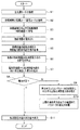
次に本実施形態の動作を具体的に説明する。図7は、本実施形態による代表的な処理動作のフローチャートを示す。
術者等の医療スタッフは、患者3に対して内視鏡観察下の手術を行う場合には、図2に示すようにトロリー装置4のトロリー装置本体12にビデオプロセッサ21,光源装置22,電気メス装置23,…,モニター26等の複数の内視鏡用周辺機器を搭載する。
また、図7のステップS1に示すように医療スタッフは、主電源コード37を商用電源の出力部(供給部)となる壁コンセント38に接続する。また、ステップS2に示すように医療スタッフは、トロリー装置4に搭載した複数の内視鏡用周辺機器(搭載機器とも言う)の電源コード21a〜26aをトロリー装置4の絶縁トランス装置14の電源出力アウトレット41a〜41fに接続し、通信コード21c〜26cを通信コネクタ受け42a〜42fに接続する。搭載機器(としての複数の内視鏡用周辺機器)は、絶縁トランス装置14に接続された接続機器となる。
Next, the operation of this embodiment will be specifically described. FIG. 7 shows a flowchart of a typical processing operation according to the present embodiment.
When a medical staff such as an operator performs an operation on the
Further, as shown in step S1 of FIG. 7, the medical staff connects the
また、ステップS3に示すように医療スタッフは、内視鏡、処置具等を対応する(搭載機器における)接続機器に接続する。具体的には、図1に示す内視鏡6をビデオプロセッサ21及び光源装置22に接続し、処置具としての電気メス8を電気メス装置23に接続し、トラカール5を気腹装置25に接続する。
次のステップS4に示すように医療スタッフは、接続機器の電源スイッチをONにする。接続機器の電源スイッチをONにすることにより、各接続機器は動作状態となり、各接続機器の制御回路は通信ポートを介して絶縁トランス装置14の通信部62と通信を行う状態となる。
次のステップS5に示すように絶縁トランス装置14の判別部63は、通信部62を用いた通信により、各接続機器の機種を判別すると共に、各接続機器の消費電力値等のデータを取得する。
Further, as shown in step S3, the medical staff connects the endoscope, the treatment tool, and the like to the corresponding connected device (in the mounted device). Specifically, the
As shown in the next step S4, the medical staff turns on the power switch of the connected device. By turning on the power switch of the connected device, each connected device is in an operating state, and the control circuit of each connected device is in a state of communicating with the
As shown in the next step S <b> 5, the
そして、判別部63は、取得したデータを電源監視ユニット61に送ると共に、メモリ64に格納する。より具体的には、メモリ64は、電気メス装置23の場合には、最大の消費電力値のデータと共に、パラメータの設定値と、該パラメータの設定値に対応する消費電力値を格納する。
次のステップS6に示すように電源監視ユニット61の消費電力算出部61aは、複数の接続機器の各消費電力値の合計値を算出する。
次のステップS7に示すように電源監視ユニット61の計算部61bは、絶縁トランス53の電源容量値から前記合計値を減算した差分を算出する。
また、次のステップS8に示すように電源監視ユニット61の制御部61dは、上記差分が正になるか否か、つまり合計値が電源容量値以内となる許容範囲内か否かを判定する。
Then, the
As shown in the next step S6, the power
As shown in the next step S <b> 7, the calculation unit 61 b of the
Further, as shown in the next step S8, the
具体例の場合には、電気メス装置23の消費電力値の最大値を用いた場合には、差分が正にならない。差分が正にならない判定結果の場合にはステップS9に示すように制御部61dは、メモリ64から差分が正となる条件を満たすパラメータの設定値に対応する消費電力値を取得し、上限設定部61cは、該消費電力値を上限の消費電力値に設定する。
図8は、電気メス装置23においては、図6Bにおいて示した第1の手術用出力設定パラメータと第2の手術用出力設定パラメータに設定した場合における各消費電力値及び各消費電力値の合計値を示す。なお、図8中では第1の手術用出力設定パラメータと第2の手術用出力設定パラメータを単に第1,第2と略記している。
第1の手術用出力設定パラメータの場合には、差分が負になるが、第2の手術用出力設定パラメータの場合には、正になるため、上限設定部61cは、電気メス装置23に対しては、第2の手術用出力設定パラメータに設定した場合の消費電力値(具体的には500VA)を上限の消費電力値に設定する。
In the case of a specific example, when the maximum value of the power consumption value of the
FIG. 8 shows that in the
In the case of the first surgical output setting parameter, the difference is negative, but in the case of the second surgical output setting parameter, the difference is positive. Thus, the power consumption value (specifically 500 VA) when the second surgical output setting parameter is set is set as the upper limit power consumption value.
また、ステップS10に示すように制御部61dは、手術等での使用中における電気メス装置23のパラメータの設定値の変化範囲を上記上限の消費電力値以下を満たす範囲内に制限する制御を行う。具体的には、制御部61dは、通信部62を介して電気メス装置23の制御回路73cに上限の消費電力値のデータを送る。制御回路73cは、手術等での使用中における電気メス装置23のパラメータの設定値の変化範囲を上限の消費電力値以下を満たす範囲内に制限する制御を行う。
ステップS10の処理の後、又はステップS8において差分が正となる判定結果の場合には、ステップS11に示すように表示パネル28は、複数の接続機器の各消費電力値の合計値を表示し、図7の処理を終了する。
図9は、図7のステップS9の上限の消費電力値の設定処理の詳細を示す。図9の処理が開始すると、ステップS21において上限設定部61cは、メモリ64から電気メス装置23の消費電力値のデータを取得する(読み取る)。
Further, as shown in step S10, the
After the process of step S10 or in the case of a determination result in which the difference is positive in step S8, as shown in step S11, the
FIG. 9 shows the details of the upper limit power consumption value setting process in step S9 of FIG. When the process of FIG. 9 is started, the upper limit setting unit 61c acquires (reads) the power consumption value data of the
そして、次のステップS22において上限設定部61cは、取得した消費電力値において差分が正となるものが有るか否かを判定する。差分が正となる消費電力値が存在する場合には、優先度が設定されているか否かを判定する。
優先度が設定されている場合には、次のステップS24において上限設定部61cは、優先度が最も高く設定されている場合の消費電力値を上限の消費電力値に設定する処理を行い、図9の処理を終了する(この場合、図7のステップS10の処理に移る)。
ステップS23において優先度が設定されていない場合には、ステップS25において上限設定部61cは、差分が設定値以上の値(マージン)を有する範囲において、差分が最も小さくなる場合の消費電力値を上限の消費電力値に設定する処理を行い、図9の処理を終了する。
Then, in the next step S22, the upper limit setting unit 61c determines whether or not there is an acquired power consumption value that has a positive difference. If there is a power consumption value with a positive difference, it is determined whether or not priority is set.
When the priority is set, in the next step S24, the upper limit setting unit 61c performs a process of setting the power consumption value when the priority is set highest to the upper limit power consumption value. 9 is terminated (in this case, the process proceeds to step S10 in FIG. 7).
When the priority is not set in step S23, in step S25, the upper limit setting unit 61c sets the upper limit of the power consumption value when the difference is the smallest in the range where the difference has a value (margin) equal to or larger than the set value. 9 is performed, and the process of FIG. 9 is terminated.
また、ステップS22において差分が正となる消費電力値が存在しない場合には、ステップS26において上限設定部61cは、手術する場合において電気メス装置23に対して確保したい消費電力値の最大値を入力するように告知する。術者は告知を受けて、ステップS27において手術する場合において電気メス装置23に対して確保したい消費電力値の最大値のデータを入力部66から入力する。ステップS28において上限設定部61cは、入力され消費電力値の最大値が、差分を正にする条件を満たすものである場合には、入力された消費電力値の最大値を上限の消費電力値に設定する処理を行い、図9の処理を終了する。
また、図10は、図7のステップS10の詳細な処理例を示す。上限の消費電力値の設定が開始すると、ステップS31に示すように制御部61dは、通信部62を介して電気メス装置23の制御回路73cに上限の消費電力値のデータを送信する。ステップS32に示すように上限の消費電力値のデータを受信した制御回路73cは、電気メス装置23の使用時における消費電力値の最大値を、この上限の消費電力値以下となるように、複数種類のパラメータの可変範囲の設定を行う。
In addition, when there is no power consumption value at which the difference is positive in step S22, in step S26, the upper limit setting unit 61c inputs the maximum value of the power consumption value to be secured for the
FIG. 10 shows a detailed processing example of step S10 of FIG. When the setting of the upper limit power consumption value starts, the
例えば上限の消費電力値を500VAに設定した場合には、電気メス装置23の操作パネル73dが操作されて出力モードや出力設定モードのパラメータの設定値が設定される場合、対応する消費電力値が上限の消費電力値としての500VA以内となるようにパラメータの可変範囲を設定する。
次のステップS33に示すように制御回路73cは、操作パネル73dの操作により設定される複数種類のパラメータの設定値をモニタする。
次のステップS34に示すように制御回路73cは、設定された複数種類のパラメータの設定値が上記の可変範囲内か否かの判定を行う。
パラメータの設定値が可変範囲内と判定された場合には、次のステップS35に示すように制御回路73cは、複数種類のパラメータの設定値を受け付け、受け付けた複数種類のパラメータの設定値に対応する制御動作を行う。例えば、制御回路73cは、設定された出力モードとなるように波形発生回路73gを制御したり、出力設定値に対応した高周波信号を出力できるようにアンプ回路73hの出力ゲインを制御したりする。ステップS35の処理の後、ステップS33の処理に戻る。
For example, when the upper limit power consumption value is set to 500 VA, when the
As shown in the next step S33, the control circuit 73c monitors the set values of a plurality of types of parameters set by operating the
As shown in the next step S34, the control circuit 73c determines whether or not the set values of the plural types of parameters that are set are within the variable range.
When it is determined that the parameter setting values are within the variable range, the control circuit 73c accepts the setting values of a plurality of types of parameters and corresponds to the received setting values of the plurality of types of parameters as shown in the next step S35. Perform the control action. For example, the control circuit 73c controls the
このようにして、パラメータの設定値が可変範囲内と判定された場合には、術者は設定されたパラメータの設定値で電気メス装置23を使用して電気メス8による手術を行うことができる。
ステップS34において複数種類のパラメータの設定値が可変範囲内から逸脱すると判定された場合には、ステップS36に示すように制御回路73cは、当該複数種類のパラメータの設定値における可変範囲以内となるように当該パラメータの設定値を制限する。
具体的には、例えば切開モードにおける出力設定値のパラメータが、130Wに設定された場合には、制御回路73cは、出力設定値のパラメータを125Wに制限する。また、ステップS37に示すようにこのように制限した内容を電気メス装置23の表示部等で告知する。
In this way, when it is determined that the parameter setting value is within the variable range, the surgeon can perform an operation with the
If it is determined in step S34 that the setting values of the plurality of types of parameters deviate from the variable range, as shown in step S36, the control circuit 73c is within the variable range of the setting values of the plurality of types of parameters. Limit the set value of the parameter.
Specifically, for example, when the parameter of the output setting value in the incision mode is set to 130W, the control circuit 73c limits the parameter of the output setting value to 125W. Further, as shown in step S37, the contents restricted in this way are notified on the display unit of the
次のステップS37の処理を行った後、図10の処理を終了する。なお、図10において説明した制御回路73cが制御する内容を、電源監視ユニット61(の制御部61d)が制御するようにしても良い。
このように動作するトロリー装置4を備えた内視鏡システム1によれば、電気メス装置23のようにパラメータの設定値により、その消費電力値が大きく変化するような(特定の)内視鏡用周辺機器を備えた場合においても、その(特定の)内視鏡用周辺機器における手術等において実際に使用する場合の消費電力値の最大値を上限の消費電力値に設定し、該上限の消費電力値以下の範囲内となるようにパラメータの設定値の変化を制限するようにしているので、1台のトロリー装置4により数多くの内視鏡用周辺機器を動作させるための交流電源を供給することができる。
After performing the process of the next step S37, the process of FIG. Note that the power monitoring unit 61 (the
According to the
また、手術等を行っている最中にパラメータの設定値を変更して処置を行った場合にも、上限の消費電力値以下に制限するように制御を行うので、ブレーカー52が交流電源を遮断してしまうような事態が発生することを防止でき、術者は手術を円滑に行うことができる。
また、術者は、手術等を行っている最中にパラメータの設定値を変更した場合に対して、消費電力値が絶縁トランス53の電源容量値以下の許容される条件を満たすように操作パネルから手動設定する操作を不必要とするため、術者が操作する手間を軽減して利便性を向上できる。
また、本実施形態によれば、術者は、予め所定の手技又は手術を行う場合の各種のパラメータの設定を入力部66等から行うことにより、電源監視ユニット61(の制御部61d)又は制御回路73cが当該所定の手技に適切に対応した制御を行うこともできる場合の説明を行う。
In addition, even when a procedure is performed while changing the parameter setting value during surgery, the
In addition, when the operator changes the parameter setting value during surgery or the like, the operation panel is set so that the power consumption value satisfies an allowable condition equal to or less than the power supply capacity value of the
In addition, according to the present embodiment, the operator sets various parameters in advance when performing a predetermined procedure or operation from the
所定の手技(又は手術)として、例えば第1の実施形態における図6Bに示した第2の手術設定用パラメータに近い設定内容で手術を行う場合で説明する。例えば切開の場合の出力が125Wでなく、例えば140Wで行い、その場合の消費電力値が550VAになり、切開以外の凝固と混合は図6Bの第2の手術設定用パラメータの場合と同じであるとする。
また、この場合に使用する内視鏡用周辺機器としては、6つの内視鏡用周辺機器におけるビデオプリンタ24のみを必要としない設定であるとする。
この場合には、トロリー装置4にビデオプリンタ24を搭載しないか、トロリー装置4にビデオプリンタ24を搭載しても絶縁トランス装置14からビデオプリンタ24に交流電源を供給しない設定にすれば良い。
ビデオプリンタ24に交流電源を供給しない設定として、ビデオプリンタ24の電源プラグ24bを電源出力アウトレット41dに接続しないようにすれば良い。又は、以下に説明するように電源出力アウトレット41dから交流電源を出力しないように制御しても良い。
As a predetermined procedure (or surgery), for example, a case will be described where surgery is performed with setting contents close to the second surgery setting parameter shown in FIG. 6B in the first embodiment. For example, the output in the case of the incision is not 125 W, for example, 140 W, the power consumption value in that case is 550 VA, and the coagulation and mixing other than the incision are the same as in the case of the second surgical setting parameter in FIG. 6B. And
Further, it is assumed that the endoscope peripheral device used in this case is a setting that does not require only the
In this case, the
As a setting for not supplying AC power to the
例えば、図4において電源線56d、57dの途中に点線で示すリレースイッチ74dを設け、リレースイッチ74dのON/OFFを電源監視ユニット61(の制御部61d等)が制御できるような構成にする。
そして、少なくとも電気メス装置23が切開モードに設定される場合には、電源監視ユニット61(の制御部61d等)はリレースイッチ74dをOFFにして、切開モードで140Wの出力で処置を行った場合にも、電気メス装置23を含む複数の内視鏡用周辺機器の各消費電力値の合計値が電源容量値以下となるように制御する。なお、電気メス装置23で手術又は手技を行う場合、上記のように特定のモード(としての切開モード)の期間を少なくとも含むように、ビデオプリンタ24に交流電源を供給しないようにリレースイッチ74dをOFFにしても良いが、手術又は手技を行う場合の期間、使用しない医療用周辺機器としてのビデオプリンタ24に交流電源を供給しないようにリレースイッチ74dをOFFにしても良い。また、ビデオプリンタ24以外の内視鏡用周辺機器に対しても交流電源の供給を停止できるようにリレースイッチを設けるようにしても良い。
図11は、トロリー装置4に搭載された内視鏡用周辺機器において、これから手技又は手術を行う場合に、一部の内視鏡用周辺機器を使用しない場合にも対応する処理例を示す。図11におけるステップS1からS5までは図7と同じである。ステップS5の次のステップS41において術者は手技又は手術に使用しない機種の内視鏡用周辺機器を入力部66から指定(入力)する。
For example, in FIG. 4, a relay switch 74d indicated by a dotted line is provided in the middle of the
When at least the
FIG. 11 shows an example of processing corresponding to a case where some of the peripheral devices for endoscope are not used when performing a procedure or surgery in the peripheral devices for endoscope mounted on the trolley device 4. Steps S1 to S5 in FIG. 11 are the same as those in FIG. In step S41 subsequent to step S5, the operator designates (inputs) an endoscope peripheral device of a model not used for the procedure or the operation from the
次のステップS42において電源監視ユニット61又は判別部63は、絶縁トランス装置14に接続された複数の接続機器において、入力部66から入力された使用しない接続機器が有る(含まれる)か否かの判定を行う。使用しない接続機器が無い判定の場合には、図7のステップS6の処理に進む。
一方、使用しない接続機器が有る判定の場合には、ステップS43において例えば電源監視ユニット61(の制御部61d)は、使用しない接続機器に交流電源を供給するリレースイッチをOFFにする。そして、使用しない接続機器には交流電源が供給されない状態となる。上記の具体例においては、リレースイッチ74dがOFFにされ、ビデオプリンタ24は、電源スイッチのON,OFFに依らず常時交流電源が供給されない状態となる。ステップS43の処理の後、図7のステップS6の処理に進む。
このように処理する構成にした場合、トロリー装置4に搭載した複数の内視鏡用周辺機器の一部を手技又は手術に使用しない場合においても、適切に手技又は手術を行うことができる。
In the next step S42, the power
On the other hand, if it is determined that there is a connection device that is not used, in step S43, for example, the power monitoring unit 61 (the
When the processing is performed in this way, even when some of the plurality of endoscope peripheral devices mounted on the trolley device 4 are not used for the procedure or surgery, the procedure or surgery can be performed appropriately.
上述した実施形態は、複数の請求項に対応した構成例を示しているが、それぞれの請求項に対応した構成にしても良い。例えば、図4に示した構成から、請求項1に対応した構成要素のみに簡略化した構成にしても良い。また、図4の構成における少なくとも請求項1を備えた構成を最小単位の構成とし、最小単位の構成において図4に示した範囲内の構成要素を追加して複数の異なる実施形態を構成しても良い。
なお、電源監視ユニット61における消費電力算出部61a,計算部61b,上限設定部61c,制御部61dをCPU等により構成しても良いが、専用のハードウェアを用いて構成しても良い。また、判別部63における接続機種判別部63a,取得部63b等もCPU等により構成しても良いが、専用のハードウェアを用いて構成しても良い。
また、上述の実施形態においては、特定の内視鏡用周辺機器として、電気メス装置の場合で説明したが、電気メス装置の場合に限定されるものでなく、超音波により処置を行う場合の超音波装置の場合にも適用することができる。また、複数の内視鏡用周辺機器のなかに特定の内視鏡用周辺機器が、1台の場合で説明したが、2台以上、存在する場合にも適用できる。また、上述した複数の内視鏡用周辺機器において、電気メス装置23を除くものは、パラメータの設定値の変化に対する消費電力値の変化が小さい内視鏡用周辺機器として説明したが、パラメータの設定値の変化に対する消費電力値の変化が小さくない種類の内視鏡用周辺機器の場合にも適用できる。例えば、光源装置22として、ランプ72hの代わりに複数のLEDを用いて、複数のLEDの発光させる数を制御することにより、照明光の光量を変化させるような構成にした場合には、照明光量を可変するパラメータに応じて発光するLEDの数が変化するために光源装置22の消費電力値が変化する。このような場合には、使用時の消費電力値の最大値を、上限の消費電力値に設定して、その上限の消費電力値以下となる範囲内で照明光量を可変するパラメータの変化を制限するようにしても良い。光源装置22の場合で説明したが、光源装置以外の内視鏡用周辺機器の場合にも適用できる。
Although the above-described embodiment shows a configuration example corresponding to a plurality of claims, a configuration corresponding to each claim may be adopted. For example, the configuration shown in FIG. 4 may be simplified to only the components corresponding to the first aspect. Further, the configuration having at
The power
Further, in the above-described embodiment, the case where an electric scalpel device is used as a specific endoscope peripheral device has been described. However, the present invention is not limited to the case of an electric scalpel device, and a case where treatment is performed using ultrasonic waves. The present invention can also be applied to an ultrasonic apparatus. Moreover, although the case where there is one specific peripheral device for endoscope among the plurality of peripheral devices for endoscope has been described, the present invention can also be applied to the case where there are two or more specific peripheral devices for endoscope. Further, in the plurality of endoscope peripheral devices described above, the one excluding the
1…内視鏡システム、4…トロリー装置、6…内視鏡、8…電気メス、11…載置台、12…トロリー装置本体、14…絶縁トランス装置、21…ビデオプロセッサ、22…光源装置、23…電気メス装置、24…ビデプリンタ、25…気腹装置、26…モニター、28…表示パネル、37…主電源コード、41…電源出力アウトレット部、42…通信コネクタ受け部、41a〜41f…電源プラグ、42a〜42f…通信コネクタ受け、53…絶縁トランス、54…電圧計、55a〜55f…電流計、61…電源監視ユニット、61a…消費電力算出部、61b…計算部、61c…上限設定部、61d…制御部、62…通信部、63…判別部、63a…接続機種判別部、63b…取得部、64…メモリ、66…入力部、
DESCRIPTION OF
Claims (8)
商用電源に1次コイル側が接続され、前記1次コイルと絶縁された2次コイルから前記商用電源と絶縁された交流電源を供給する絶縁トランスを備えた絶縁トランス装置と、
絶縁トランスの2次コイル側に設けられ、前記複数の内視鏡用周辺機器の電源入力端がそれぞれ接続され、接続された前記電源入力端にそれぞれ前記交流電源を供給する複数の電源出力部と、
前記複数の電源出力部に接続された前記複数の内視鏡用周辺機器の機種を判別する接続機種判別部と、
前記接続機種判別部による前記機種の判別結果と共に、前記複数の電源出力部に接続された前記複数の内視鏡用周辺機器の各消費電力値、又は前記各消費電力値を算出するための各パラメータを取得する取得部と、
前記取得部の取得結果に応じて前記複数の電源出力部に接続された前記複数の内視鏡用周辺機器の前記各消費電力値の合計値を算出する消費電力算出部と、
前記絶縁トランスが供給可能とする電源容量値から前記消費電力算出部により算出された前記合計値を減算した差分を計算する計算部と、
前記計算部により計算された前記差分が正となる条件を満たすように、少なくとも前記複数の電源出力部に接続された前記複数の内視鏡用周辺機器のうち、前記パラメータの設定値に応じて消費電力値が実質的に変化する、前記接続機種判別によって判別された特定の機種としての特定の内視鏡用周辺機器に対して、前記計算部により計算された前記差分が正となる条件を満たすような前記パラメータの設定値に応じた消費電力値を、前記特定の内視鏡用周辺機器の使用時における上限の消費電力値に設定する上限設定部と、
前記特定の内視鏡用周辺機器に対して前記上限の消費電力値のデータを送信することで、少なくとも前記特定の内視鏡用周辺機器を使用中に設定される前記パラメータの設定値が前記上限設定部により設定された前記上限の消費電力値以下の範囲内となるように、前記パラメータの設定値の変化を制限する制御を前記特定の内視鏡用周辺機器に対して行う制御部と、
を有することを特徴とするトロリー装置。 A mounting portion that can mount a plurality of endoscope peripheral devices;
An insulation transformer device comprising an insulation transformer connected to a commercial power supply at a primary coil side and supplying an AC power supply insulated from the commercial power supply from a secondary coil insulated from the primary coil;
A plurality of power output units provided on the secondary coil side of the isolation transformer, connected to power input terminals of the plurality of peripheral devices for endoscope, and supplying the AC power to the connected power input terminals; ,
A connected model discriminating unit for discriminating models of the plurality of endoscope peripheral devices connected to the plurality of power output units;
Along with the determination result of the model by the connected model determination unit, each power consumption value of the plurality of endoscope peripheral devices connected to the plurality of power supply output units, or each power consumption value to calculate each power consumption value An acquisition unit for acquiring parameters;
A power consumption calculation unit that calculates a total value of the respective power consumption values of the plurality of endoscope peripheral devices connected to the plurality of power output units according to the acquisition result of the acquisition unit;
A calculation unit that calculates a difference obtained by subtracting the total value calculated by the power consumption calculation unit from a power supply capacity value that can be supplied by the isolation transformer;
According to the set value of the parameter among the plurality of peripheral devices for endoscope connected to at least the plurality of power output units so that the condition calculated by the calculation unit is positive is satisfied. With respect to a specific endoscope peripheral device as a specific model determined by the connected model determination, the power consumption value changes substantially, a condition that the difference calculated by the calculation unit is positive An upper limit setting unit that sets the power consumption value according to the set value of the parameter to satisfy the upper limit power consumption value when using the specific peripheral device for endoscope ,
Wherein the relative specific endoscope peripheral device to send data of the power consumption value of the upper limit set value of the parameter to be set while using peripherals least the particular endoscope wherein A control unit that performs control for limiting the change in the set value of the parameter to the specific peripheral device for endoscope so as to be within the range of the power consumption value of the upper limit set by the upper limit setting unit; ,
A trolley device comprising:
前記特定の内視鏡用周辺機器における前記パラメータの少なくとも1つを構成する第1のパラメータとして、前記エネルギー出力部が出力するエネルギー出力値を変更可能に設定する操作を行う第1のパラメータ設定操作部と、
前記第1のパラメータ設定操作部の操作に応じて、前記エネルギー出力部が出力するエネルギー出力値を制御する制御回路と、
前記絶縁トランス装置に設けられた絶縁トランス装置側通信部と通信を行う通信部と、
を有する前記特定の内視鏡用周辺機器が搭載されている際に、
前記制御部は、前記上限の消費電力値のデータを通信により前記制御回路に送信し、前記制御回路を介して前記上限の消費電力値以下となるように前記エネルギー出力部が出力するエネルギー出力値を制御することを特徴とする請求項2に記載のトロリー装置。 An energy output unit that outputs energy for treating a predetermined treatment instrument to the mounting unit ;
A first parameter setting operation for performing an operation of setting an energy output value output from the energy output unit to be changeable as a first parameter constituting at least one of the parameters in the specific peripheral device for endoscope And
A control circuit for controlling an energy output value output by the energy output unit in response to an operation of the first parameter setting operation unit;
A communication unit that communicates with an insulation transformer device side communication unit provided in the insulation transformer device;
When the specific endoscope peripheral devices have a are mounted,
The control unit transmits data of the upper limit power consumption value to the control circuit by communication, and the energy output value output by the energy output unit to be equal to or lower than the upper limit power consumption value via the control circuit The trolley device according to claim 2 , wherein the trolley device is controlled.
前記特定の内視鏡用周辺機器における前記パラメータとして、前記エネルギー出力部が出力するエネルギー出力値を変更可能に設定する操作を行う操作パネルと、
前記操作パネルの操作に応じて、前記エネルギー出力部が出力するエネルギー出力値を制御する制御回路と、
前記絶縁トランス装置に設けられた絶縁トランス装置側通信部と通信を行う通信部と、
を有する前記特定の内視鏡用周辺機器が搭載されている際に、
前記制御部は、前記上限の消費電力値のデータを通信により前記制御回路に送信し、前記制御回路を介して前記上限の消費電力値以下となるように前記エネルギー出力部が出力するエネルギー出力値を制御することを特徴とする請求項2に記載のトロリー装置。 An energy output unit that outputs energy for treating a predetermined treatment instrument to the mounting unit ;
An operation panel for performing an operation of setting the energy output value output by the energy output unit to be changeable as the parameter in the specific peripheral device for endoscope,
A control circuit for controlling an energy output value output by the energy output unit in response to an operation of the operation panel;
A communication unit that communicates with an insulation transformer device side communication unit provided in the insulation transformer device;
When the specific endoscope peripheral devices have a are mounted,
The control unit transmits data of the upper limit power consumption value to the control circuit by communication, and the energy output value output by the energy output unit to be equal to or lower than the upper limit power consumption value via the control circuit The trolley device according to claim 2, wherein the trolley device is controlled.
前記計算部により計算された前記差分が正とならない場合には、前記上限設定部は、前記特定の内視鏡用周辺機器に対して、該特定の内視鏡用周辺機器の消費電力最大値の代わりに、使用時における消費電力値の最大値を用いた場合の当該消費電力値の最大値及び前記特定の内視鏡用周辺機器を除く前記複数の内視鏡用周辺機器における前記各消費電力最大値の合計値を第2の合計値として算出し、前記計算部は、前記電源容量値から当該第2の合計値を減算した差分を算出し、前記計算部により計算された前記差分が正となる場合には、前記使用時における前記消費電力値の最大値を前記特定の内視鏡用周辺機器における前記上限の消費電力値に設定することを特徴とする請求項1に記載のトロリー装置。 Before Quito resulting unit acquires first respective power maximum value to be consumed to the maximum in each of the plurality of endoscope peripheral devices including the particular endoscope peripheral device as the respective power consumption value, The power consumption calculation unit calculates a total value of the power consumption maximum values, and the calculation unit calculates a difference obtained by subtracting the total value of the power consumption maximum values from the power supply capacity value.
When the difference calculated by the calculation unit is not positive, the upper limit setting unit, for the specific endoscope peripheral device, the power consumption maximum value of the specific endoscope peripheral device Instead of the maximum value of the power consumption value at the time of use, the maximum value of the power consumption value and the consumption of each of the plurality of endoscope peripheral devices excluding the specific endoscope peripheral device A total value of power maximum values is calculated as a second total value, and the calculation unit calculates a difference obtained by subtracting the second total value from the power supply capacity value, and the difference calculated by the calculation unit is 2. The trolley according to claim 1, wherein when it is positive, the maximum value of the power consumption value at the time of use is set to the upper limit power consumption value of the specific endoscope peripheral device. apparatus.
前記第2のパラメータの設定と前記第1のパラメータの設定の組み合わせに応じて、前記手技又は前記手術において前記特定の内視鏡用周辺機器で消費される前記消費電力値の最大値が第1の消費電力値と第1の消費電力値より小さい第2の消費電力値の間で変化する場合、前記上限設定部は、前記第1の消費電力値を前記上限の消費電力値に設定することを特徴とする請求項3に記載のトロリー装置。 In addition to the first parameter constituting the parameter in the specific endoscopic peripheral device, it is prepared for setting any of a plurality of different types of treatments in the specific endoscopic peripheral device. A second parameter setting operation unit for setting a second parameter constituting at least one of the parameters,
Depending on the combination of the setting of the second parameter and the setting of the first parameter, the maximum value of the power consumption value consumed by the specific endoscope peripheral device in the procedure or the operation is the first value. The upper limit setting unit sets the first power consumption value to the upper limit power consumption value when the power consumption value changes between the second power consumption value smaller than the first power consumption value. The trolley device according to claim 3 .
前記制御部は、少なくとも前記手技又は前記手術を行っている期間、前記第1の電源出力部から前記第1の内視鏡用周辺機器に供給する前記交流電源をOFFにするように制御することを特徴とする請求項4に記載のトロリー装置。 In the plurality of endoscope peripheral devices mounted on the mounting portion, the plurality of power input terminals of the first endoscope peripheral device as the endoscope peripheral device not used for the procedure or the surgery are the plurality of endoscope peripheral devices. When connected to the first power output unit in the power output unit of
The control unit performs control so as to turn off the AC power supplied from the first power output unit to the first endoscope peripheral device during at least the procedure or the operation. The trolley device according to claim 4.
Priority Applications (1)
| Application Number | Priority Date | Filing Date | Title |
|---|---|---|---|
| JP2013235031A JP6138027B2 (en) | 2013-11-13 | 2013-11-13 | Trolley equipment |
Applications Claiming Priority (1)
| Application Number | Priority Date | Filing Date | Title |
|---|---|---|---|
| JP2013235031A JP6138027B2 (en) | 2013-11-13 | 2013-11-13 | Trolley equipment |
Publications (2)
| Publication Number | Publication Date |
|---|---|
| JP2015093116A JP2015093116A (en) | 2015-05-18 |
| JP6138027B2 true JP6138027B2 (en) | 2017-05-31 |
Family
ID=53195935
Family Applications (1)
| Application Number | Title | Priority Date | Filing Date |
|---|---|---|---|
| JP2013235031A Active JP6138027B2 (en) | 2013-11-13 | 2013-11-13 | Trolley equipment |
Country Status (1)
| Country | Link |
|---|---|
| JP (1) | JP6138027B2 (en) |
Families Citing this family (2)
| Publication number | Priority date | Publication date | Assignee | Title |
|---|---|---|---|---|
| US11931089B2 (en) * | 2018-09-07 | 2024-03-19 | Cilag Gmbh International | Modular surgical energy system with module positional awareness sensing with voltage detection |
| CN218739142U (en) * | 2022-03-30 | 2023-03-28 | 浙江优亿医疗器械股份有限公司 | Portable endoscope trolley |
Family Cites Families (2)
| Publication number | Priority date | Publication date | Assignee | Title |
|---|---|---|---|---|
| JP2001120570A (en) * | 1999-10-26 | 2001-05-08 | Olympus Optical Co Ltd | Endoscopic system |
| JP2005296259A (en) * | 2004-04-09 | 2005-10-27 | Olympus Corp | Controller for medical system |
-
2013
- 2013-11-13 JP JP2013235031A patent/JP6138027B2/en active Active
Also Published As
| Publication number | Publication date |
|---|---|
| JP2015093116A (en) | 2015-05-18 |
Similar Documents
| Publication | Publication Date | Title |
|---|---|---|
| RU2758566C2 (en) | Gas control module for electrosurgery | |
| US11107571B2 (en) | Information processing apparatus, information processing method, program, and medical observation system | |
| US5627584A (en) | Endoscope system with centralized control of associated peripheral equipment | |
| US10117702B2 (en) | Surgical generator systems and related methods | |
| US20160296270A1 (en) | Devices and methods for providing additional power to surgical devices | |
| ES2368127T3 (en) | ELECTROCHIRURICAL INSTRUMENT. | |
| CN111526818B (en) | Situation awareness for electrosurgical systems | |
| JP6373584B2 (en) | Surgical instrument having a charging station and wireless communication | |
| JP4391706B2 (en) | Surgical system | |
| AU2012201623B2 (en) | Isolated current sensor | |
| JPH11309156A (en) | Smoke exhauster | |
| JP2011502596A (en) | Display device for electrosurgical instrument and adapter for connecting electrosurgical instrument | |
| US20220319693A1 (en) | Radio frequency identification token for wireless surgical instruments | |
| JP2024512725A (en) | Intelligent data ports for modular energy systems | |
| JP2024512720A (en) | Energy delivery mitigation for modular energy systems | |
| JP2024512721A (en) | User interface mitigation techniques for modular energy systems | |
| JP6138027B2 (en) | Trolley equipment | |
| JP2005319086A (en) | Intracavity observation system | |
| JP2014068987A (en) | Medical wireless power supply system | |
| JP2017023604A (en) | Endoscope system | |
| JP5592826B2 (en) | Pneumoperitoneum | |
| JP2006288754A (en) | Electrosurgical instrument | |
| CN105962977A (en) | Wireless transmission type pleuroperitoneal minimally-invasive device carrying with OCT technology | |
| AU2012244243B2 (en) | In-Situ proximity recognition apparatus | |
| CN114305651A (en) | Automatic smoke discharging system for operation |
Legal Events
| Date | Code | Title | Description |
|---|---|---|---|
| A711 | Notification of change in applicant |
Free format text: JAPANESE INTERMEDIATE CODE: A712 Effective date: 20150422 |
|
| RD03 | Notification of appointment of power of attorney |
Free format text: JAPANESE INTERMEDIATE CODE: A7423 Effective date: 20150525 |
|
| A621 | Written request for application examination |
Free format text: JAPANESE INTERMEDIATE CODE: A621 Effective date: 20160316 |
|
| A977 | Report on retrieval |
Free format text: JAPANESE INTERMEDIATE CODE: A971007 Effective date: 20170116 |
|
| A131 | Notification of reasons for refusal |
Free format text: JAPANESE INTERMEDIATE CODE: A131 Effective date: 20170124 |
|
| A521 | Request for written amendment filed |
Free format text: JAPANESE INTERMEDIATE CODE: A523 Effective date: 20170327 |
|
| TRDD | Decision of grant or rejection written | ||
| A01 | Written decision to grant a patent or to grant a registration (utility model) |
Free format text: JAPANESE INTERMEDIATE CODE: A01 Effective date: 20170411 |
|
| A61 | First payment of annual fees (during grant procedure) |
Free format text: JAPANESE INTERMEDIATE CODE: A61 Effective date: 20170425 |
|
| R151 | Written notification of patent or utility model registration |
Ref document number: 6138027 Country of ref document: JP Free format text: JAPANESE INTERMEDIATE CODE: R151 |
|
| R250 | Receipt of annual fees |
Free format text: JAPANESE INTERMEDIATE CODE: R250 |
|
| R250 | Receipt of annual fees |
Free format text: JAPANESE INTERMEDIATE CODE: R250 |
|
| R250 | Receipt of annual fees |
Free format text: JAPANESE INTERMEDIATE CODE: R250 |
|
| R250 | Receipt of annual fees |
Free format text: JAPANESE INTERMEDIATE CODE: R250 |