JP6125533B2 - Internal combustion engine - Google Patents
Internal combustion engine Download PDFInfo
- Publication number
- JP6125533B2 JP6125533B2 JP2014548203A JP2014548203A JP6125533B2 JP 6125533 B2 JP6125533 B2 JP 6125533B2 JP 2014548203 A JP2014548203 A JP 2014548203A JP 2014548203 A JP2014548203 A JP 2014548203A JP 6125533 B2 JP6125533 B2 JP 6125533B2
- Authority
- JP
- Japan
- Prior art keywords
- cylinder
- piston
- combustion engine
- internal combustion
- pistons
- Prior art date
- Legal status (The legal status is an assumption and is not a legal conclusion. Google has not performed a legal analysis and makes no representation as to the accuracy of the status listed.)
- Expired - Fee Related
Links
- 238000002485 combustion reaction Methods 0.000 title claims description 72
- 239000000446 fuel Substances 0.000 claims description 54
- 238000002347 injection Methods 0.000 claims description 15
- 239000007924 injection Substances 0.000 claims description 15
- 230000006835 compression Effects 0.000 description 7
- 238000007906 compression Methods 0.000 description 7
- 230000007246 mechanism Effects 0.000 description 4
- 239000000203 mixture Substances 0.000 description 4
- 230000002000 scavenging effect Effects 0.000 description 4
- 239000002826 coolant Substances 0.000 description 3
- 230000008878 coupling Effects 0.000 description 3
- 238000010168 coupling process Methods 0.000 description 3
- 238000005859 coupling reaction Methods 0.000 description 3
- 238000004880 explosion Methods 0.000 description 3
- 238000007796 conventional method Methods 0.000 description 2
- 239000007789 gas Substances 0.000 description 2
- 239000000567 combustion gas Substances 0.000 description 1
- 238000001816 cooling Methods 0.000 description 1
- 238000013461 design Methods 0.000 description 1
- 230000001939 inductive effect Effects 0.000 description 1
- 239000000314 lubricant Substances 0.000 description 1
- 238000012986 modification Methods 0.000 description 1
- 230000004048 modification Effects 0.000 description 1
- 230000002093 peripheral effect Effects 0.000 description 1
- 230000010363 phase shift Effects 0.000 description 1
- 238000010248 power generation Methods 0.000 description 1
- 238000012546 transfer Methods 0.000 description 1
Images


Classifications
-
- F—MECHANICAL ENGINEERING; LIGHTING; HEATING; WEAPONS; BLASTING
- F01—MACHINES OR ENGINES IN GENERAL; ENGINE PLANTS IN GENERAL; STEAM ENGINES
- F01B—MACHINES OR ENGINES, IN GENERAL OR OF POSITIVE-DISPLACEMENT TYPE, e.g. STEAM ENGINES
- F01B7/00—Machines or engines with two or more pistons reciprocating within same cylinder or within essentially coaxial cylinders
- F01B7/02—Machines or engines with two or more pistons reciprocating within same cylinder or within essentially coaxial cylinders with oppositely reciprocating pistons
- F01B7/04—Machines or engines with two or more pistons reciprocating within same cylinder or within essentially coaxial cylinders with oppositely reciprocating pistons acting on same main shaft
-
- F—MECHANICAL ENGINEERING; LIGHTING; HEATING; WEAPONS; BLASTING
- F02—COMBUSTION ENGINES; HOT-GAS OR COMBUSTION-PRODUCT ENGINE PLANTS
- F02B—INTERNAL-COMBUSTION PISTON ENGINES; COMBUSTION ENGINES IN GENERAL
- F02B53/00—Internal-combustion aspects of rotary-piston or oscillating-piston engines
- F02B53/02—Methods of operating
-
- F—MECHANICAL ENGINEERING; LIGHTING; HEATING; WEAPONS; BLASTING
- F01—MACHINES OR ENGINES IN GENERAL; ENGINE PLANTS IN GENERAL; STEAM ENGINES
- F01B—MACHINES OR ENGINES, IN GENERAL OR OF POSITIVE-DISPLACEMENT TYPE, e.g. STEAM ENGINES
- F01B9/00—Reciprocating-piston machines or engines characterised by connections between pistons and main shafts and not specific to preceding groups
- F01B9/02—Reciprocating-piston machines or engines characterised by connections between pistons and main shafts and not specific to preceding groups with crankshaft
- F01B9/023—Reciprocating-piston machines or engines characterised by connections between pistons and main shafts and not specific to preceding groups with crankshaft of Bourke-type or Scotch yoke
-
- F—MECHANICAL ENGINEERING; LIGHTING; HEATING; WEAPONS; BLASTING
- F01—MACHINES OR ENGINES IN GENERAL; ENGINE PLANTS IN GENERAL; STEAM ENGINES
- F01B—MACHINES OR ENGINES, IN GENERAL OR OF POSITIVE-DISPLACEMENT TYPE, e.g. STEAM ENGINES
- F01B9/00—Reciprocating-piston machines or engines characterised by connections between pistons and main shafts and not specific to preceding groups
- F01B9/02—Reciprocating-piston machines or engines characterised by connections between pistons and main shafts and not specific to preceding groups with crankshaft
- F01B9/026—Rigid connections between piston and rod; Oscillating pistons
-
- F—MECHANICAL ENGINEERING; LIGHTING; HEATING; WEAPONS; BLASTING
- F02—COMBUSTION ENGINES; HOT-GAS OR COMBUSTION-PRODUCT ENGINE PLANTS
- F02B—INTERNAL-COMBUSTION PISTON ENGINES; COMBUSTION ENGINES IN GENERAL
- F02B5/00—Engines characterised by positive ignition
-
- F—MECHANICAL ENGINEERING; LIGHTING; HEATING; WEAPONS; BLASTING
- F02—COMBUSTION ENGINES; HOT-GAS OR COMBUSTION-PRODUCT ENGINE PLANTS
- F02B—INTERNAL-COMBUSTION PISTON ENGINES; COMBUSTION ENGINES IN GENERAL
- F02B75/00—Other engines
- F02B75/16—Engines characterised by number of cylinders, e.g. single-cylinder engines
- F02B75/18—Multi-cylinder engines
- F02B75/24—Multi-cylinder engines with cylinders arranged oppositely relative to main shaft and of "flat" type
- F02B75/246—Multi-cylinder engines with cylinders arranged oppositely relative to main shaft and of "flat" type with only one crankshaft of the "pancake" type, e.g. pairs of connecting rods attached to common crankshaft bearing
-
- F—MECHANICAL ENGINEERING; LIGHTING; HEATING; WEAPONS; BLASTING
- F02—COMBUSTION ENGINES; HOT-GAS OR COMBUSTION-PRODUCT ENGINE PLANTS
- F02B—INTERNAL-COMBUSTION PISTON ENGINES; COMBUSTION ENGINES IN GENERAL
- F02B75/00—Other engines
- F02B75/28—Engines with two or more pistons reciprocating within same cylinder or within essentially coaxial cylinders
- F02B75/282—Engines with two or more pistons reciprocating within same cylinder or within essentially coaxial cylinders the pistons having equal strokes
-
- F—MECHANICAL ENGINEERING; LIGHTING; HEATING; WEAPONS; BLASTING
- F02—COMBUSTION ENGINES; HOT-GAS OR COMBUSTION-PRODUCT ENGINE PLANTS
- F02P—IGNITION, OTHER THAN COMPRESSION IGNITION, FOR INTERNAL-COMBUSTION ENGINES; TESTING OF IGNITION TIMING IN COMPRESSION-IGNITION ENGINES
- F02P15/00—Electric spark ignition having characteristics not provided for in, or of interest apart from, groups F02P1/00 - F02P13/00 and combined with layout of ignition circuits
- F02P15/04—Electric spark ignition having characteristics not provided for in, or of interest apart from, groups F02P1/00 - F02P13/00 and combined with layout of ignition circuits one of the spark electrodes being mounted on the engine working piston
-
- F—MECHANICAL ENGINEERING; LIGHTING; HEATING; WEAPONS; BLASTING
- F02—COMBUSTION ENGINES; HOT-GAS OR COMBUSTION-PRODUCT ENGINE PLANTS
- F02B—INTERNAL-COMBUSTION PISTON ENGINES; COMBUSTION ENGINES IN GENERAL
- F02B75/00—Other engines
- F02B75/02—Engines characterised by their cycles, e.g. six-stroke
- F02B2075/022—Engines characterised by their cycles, e.g. six-stroke having less than six strokes per cycle
- F02B2075/025—Engines characterised by their cycles, e.g. six-stroke having less than six strokes per cycle two
-
- F—MECHANICAL ENGINEERING; LIGHTING; HEATING; WEAPONS; BLASTING
- F02—COMBUSTION ENGINES; HOT-GAS OR COMBUSTION-PRODUCT ENGINE PLANTS
- F02D—CONTROLLING COMBUSTION ENGINES
- F02D2400/00—Control systems adapted for specific engine types; Special features of engine control systems not otherwise provided for; Power supply, connectors or cabling for engine control systems
- F02D2400/04—Two-stroke combustion engines with electronic control
-
- F—MECHANICAL ENGINEERING; LIGHTING; HEATING; WEAPONS; BLASTING
- F02—COMBUSTION ENGINES; HOT-GAS OR COMBUSTION-PRODUCT ENGINE PLANTS
- F02P—IGNITION, OTHER THAN COMPRESSION IGNITION, FOR INTERNAL-COMBUSTION ENGINES; TESTING OF IGNITION TIMING IN COMPRESSION-IGNITION ENGINES
- F02P3/00—Other installations
- F02P3/02—Other installations having inductive energy storage, e.g. arrangements of induction coils
Description
本発明は内燃機関に関する。特にこれは、対向ピストン構成を有する内燃機関に関する。 The present invention relates to an internal combustion engine. In particular, this relates to an internal combustion engine having an opposed piston configuration.
国際公開第2008/149061号パンフレット(Cox Powertrain)は2気筒2ストローク直噴式内燃機関について記載している。2つのシリンダは水平に対向し、各シリンダ内には対向する往復動ピストンがあり、それらの間に燃焼室が形成される。ピストンは2つのシリンダの間の中央クランクシャフトを駆動する。各シリンダ内の内側ピストン(すなわちクランクシャフトにより近いピストン)が一対の並列のスコッチヨーク機構を介してクランクシャフトを駆動する。各シリンダの外側ピストンが、内側ピストンの2つのスコッチヨーク機構の間に入れ子状になっている第3のスコッチヨークを介して、クランクシャフトを、内側ピストンの中心を通るドライブロッドによって駆動する。コネクティングロッドは中空管状形態を有し、コネクティングロッド内に収容される燃料噴射器によって燃料が燃焼室に噴射される。コネクティングロッドの壁は一連の周方向に離間した孔を有し、それを通じて、側方に外側に向かって燃焼室内に燃料が放出される。 International Publication No. 2008/149061 (Cox Powertrain) describes a two-cylinder two-stroke direct injection internal combustion engine. The two cylinders are horizontally opposed and there are opposed reciprocating pistons in each cylinder, between which a combustion chamber is formed. The piston drives the central crankshaft between the two cylinders. An inner piston (ie, a piston closer to the crankshaft) in each cylinder drives the crankshaft through a pair of parallel scotch yoke mechanisms. The outer piston of each cylinder drives the crankshaft by a drive rod that passes through the center of the inner piston through a third scotch yoke nested between the two scotch yoke mechanisms of the inner piston. The connecting rod has a hollow tubular shape, and fuel is injected into the combustion chamber by a fuel injector housed in the connecting rod. The connecting rod wall has a series of circumferentially spaced holes through which fuel is discharged laterally and outwardly into the combustion chamber.
本発明は、概して、シリンダ内の2つの対向する往復動ピストン間に形成された燃焼室内で燃焼を起こすか補助するためのスパークプラグを各シリンダ内に有する対向ピストン式内燃機関に関する。このようにして、対向ピストンエンジンの「スパーク点火」又は「スパーク補助」の変形例を提供することが可能となる。これは、エンジンを作動させる燃料としてより多様な燃料を使用できる機会を創出する。圧縮点火エンジンに要求される高圧縮比(典型的には、15:1以上)はスパーク点火エンジンには必要でなく、ここでは、圧縮比は約10:1で十分である。 The present invention generally relates to an opposed piston internal combustion engine having a spark plug in each cylinder for causing or assisting combustion in a combustion chamber formed between two opposing reciprocating pistons in the cylinder. In this way, it is possible to provide a variant of “spark ignition” or “spark assistance” of the opposed piston engine. This creates an opportunity to use a wider variety of fuels as fuel to operate the engine. The high compression ratio required for compression ignition engines (typically greater than 15: 1) is not necessary for spark ignition engines, where a compression ratio of about 10: 1 is sufficient.
第1の態様では、本発明は、少なくとも1つのシリンダと、シリンダ内の対向する往復動ピストンの対であって、それらの間に燃焼室を形成するピストンの対と、前記シリンダに取り付けられた少なくとも1つの燃焼点火装置であって、前記対向するピストンの間に形成される前記燃焼室内にその一部が露出する燃焼点火装置とを備えた内燃機関を提供する。 In a first aspect, the present invention is attached to said cylinder, at least one cylinder and a pair of opposing reciprocating pistons in the cylinder, the pair of pistons forming a combustion chamber therebetween. Provided is an internal combustion engine comprising at least one combustion ignition device, a combustion ignition device partially exposed in the combustion chamber formed between the opposed pistons.
燃焼点火装置は、例えば、スパークプラグ、プラズマスパーク発生器又はグロープラグであってもよい。便宜上、燃焼点火装置は、「スパークプラグ」として以下に参照されるものの、文脈上許される場合、プラズマスパーク発生器、グロープラグ、又は、シリンダ内の燃料又は混合気の点火又は点火を補助するための他の任意の適切な手段を含む。 The combustion ignition device may be, for example, a spark plug, a plasma spark generator, or a glow plug. For convenience, a combustion igniter, referred to below as a “spark plug”, to assist in the ignition or ignition of a plasma spark generator, a glow plug, or a fuel or mixture in a cylinder, if allowed by context Including any other suitable means.
特に、スパークプラグを1つのみ用いる場合、スパークプラグは、シリンダ又はピストンの中心軸線上又はその近傍にあることが好ましい。スパークプラグの電極は、通常、スパークプラグの一端(シリンダ内に突出する端部)にある。 In particular, when only one spark plug is used, the spark plug is preferably on or near the central axis of the cylinder or piston. The electrode of the spark plug is usually at one end of the spark plug (the end protruding into the cylinder).
いくつかの実施形態では、スパークプラグはシリンダの一端に固定され、典型的には、所定の構成部品に固定されており、その端部から、シリンダの中心軸線に沿って又は平行してシリンダ内に突出し、エンジンサイクルを通して、燃焼室内の定位置に配置される。この場合、スパークプラグが突出するシリンダの端部に最も接近したピストンをスパークプラグが貫通し、このピストンはスパークプラグが内部に収容されたハウジングに沿って往復運動するように構成されている。 In some embodiments, the spark plug is secured to one end of the cylinder and is typically secured to a predetermined component from within that cylinder along or parallel to the central axis of the cylinder. And is disposed at a fixed position in the combustion chamber through the engine cycle. In this case, the spark plug passes through the piston closest to the end of the cylinder from which the spark plug protrudes, and the piston is configured to reciprocate along the housing in which the spark plug is accommodated.
別の構成では、スパークプラグはピストンの1つに固定され、ピストンと共に動く。この場合、可撓リード線や、ブラシ又は非接触の電気接続(例えば、誘導結合)のような摺動電気接続を、点火プラグに電力を提供するために使用してもよい。 In another configuration, the spark plug is secured to one of the pistons and moves with the piston. In this case, a flexible electrical lead or a sliding electrical connection such as a brush or a contactless electrical connection (eg inductive coupling) may be used to provide power to the spark plug.
通常、ピストンの運動が、シリンダの一端に配置されたクランクシャフトを駆動する。シリンダのクランクシャフト端に最も近いピストンは「内側ピストン」と称され、クランクシャフトから最も遠いピストンは「外側ピストン」と称される。このスパークプラグ又は各スパークプラグを、外側ピストン又は内側ピストンのいずれかに取り付けてもよい。 Usually, the movement of the piston drives a crankshaft located at one end of the cylinder. The piston closest to the crankshaft end of the cylinder is called the “inner piston” and the piston farthest from the crankshaft is called the “outer piston”. This spark plug or each spark plug may be attached to either the outer piston or the inner piston.
特に、スパークプラグが固定されており、取り付けられた(例えば外側)ピストンがスパークプラグのハウジングに沿って往復運動する場合、スパークプラグは冷却されることが好ましい。冷却は、例えば、空気、オイル、又はエンジン冷却剤、又はこれらの組み合わせによって行うことができる。 In particular, when the spark plug is fixed and the attached (eg, outer) piston reciprocates along the spark plug housing, the spark plug is preferably cooled. Cooling can be accomplished, for example, with air, oil, or engine coolant, or a combination thereof.
ピストンの1つがスパークプラグのハウジング上で往復運動する場合、ハウジングの外側表面が滑動面となり、それに沿ってピストンが摺動することができることが好ましい。例えば、1つ又は複数のシールリングのようなシールシステムがピストンとハウジングの滑動面との間に設けられ、燃焼室への燃焼ガスの漏れ及び潤滑油の移入を規制する。 When one of the pistons reciprocates on the spark plug housing, it is preferred that the outer surface of the housing be a sliding surface along which the piston can slide. For example, a seal system, such as one or more seal rings, is provided between the piston and the sliding surface of the housing to regulate the leakage of combustion gases and the transfer of lubricant into the combustion chamber.
スパークプラグは、任意の適切な継手によって、エンジン構造の外側部分に、直接又は間接的に固定してもよい。一般的には、スパークプラグは、スパークプラグのハウジングに固定され、ハウジングは、エンジン構造の外側部分に固定される。場合よっては、スパークプラグのハウジングがシリンダの中心線と平行に自己調心することを可能にしたり、スパークプラグのハウジングが取り付けられたピストンの公差や熱ひずみを吸収することを可能にする継手を使用することが望ましい場合がある。例えば、オルダム継手を使用してもよい(このタイプの継手は、スパークプラグのハウジングがその軸線に垂直な平面内で動くことを可能にして所望の配置を可能にする一方、その軸線に沿った動きを妨げる)。 The spark plug may be secured directly or indirectly to the outer portion of the engine structure by any suitable fitting. Generally, the spark plug is secured to the spark plug housing and the housing is secured to the outer portion of the engine structure. In some cases, a fitting that allows the spark plug housing to be self-aligning parallel to the cylinder centerline or to absorb the tolerance and thermal strain of the piston to which the spark plug housing is attached. It may be desirable to use it. For example, an Oldham coupling may be used (this type of coupling allows the spark plug housing to move in a plane perpendicular to its axis, while allowing the desired placement, while along its axis. Hinder movement).
本発明の実施形態は、直噴エンジン又は燃料がシリンダ内へ直接噴射されない種類のエンジンとすることができる。後者は、「ポート燃料噴射」又は「マニホールド燃料噴射」(以下においては、概して、「間接噴射」と称される)として例示される。 Embodiments of the present invention can be a direct injection engine or an engine of a type where fuel is not directly injected into the cylinder. The latter is illustrated as “port fuel injection” or “manifold fuel injection” (hereinafter generally referred to as “indirect injection”).
間接噴射の実施形態はシングルポイントであってもマルチポイントであってもよい。シングルポイントの間接噴射の実施形態では、燃料は、典型的には、エンジンの吸気マニホールドの中心点に注入され、そこから複数のエンジンシリンダ内に導入される。一方で、マルチポイント噴射の実施形態では、各シリンダに取り付けられた1又は複数の燃料噴射器が、吸気マニホールド、又は、シリンダの吸気ポートに露出したランナへ燃料を噴射し、燃料はそこから吸気ポートを通ってシリンダ内へ移る。 Indirect injection embodiments may be single point or multipoint. In the single point indirect injection embodiment, fuel is typically injected into the center point of the intake manifold of the engine and from there into a plurality of engine cylinders. On the other hand, in the multi-point injection embodiment, one or more fuel injectors attached to each cylinder inject fuel into an intake manifold or runner exposed in the intake port of the cylinder from which the fuel is drawn. Move through the port into the cylinder.
本発明の直接噴射の実施形態は、シリンダの燃焼室に直接露出するノズルを有する少なくとも1つの燃料噴射器を備える。例えば、噴射器は、シリンダの側壁に取り付けてもよい。あるいは、噴射器は、シリンダの一端に取り付けられて、噴射器のノズルがシリンダの一端でそれぞれのピストンクラウンを貫通して燃焼室内に突出してもよい。スパークプラグと同様に、燃料噴射器がピストンの1つに取り付けられる場合では、シリンダ内の位置に固定されてピストンがその周囲を摺動するものとしてもよいし、シリンダ内でピストンが往復運動するのと共に動くものとしてもよい。 The direct injection embodiment of the present invention comprises at least one fuel injector having a nozzle that is directly exposed to the combustion chamber of the cylinder. For example, the injector may be attached to the side wall of the cylinder. Alternatively, the injector may be attached to one end of the cylinder, and the nozzle of the injector may penetrate each piston crown at one end of the cylinder and protrude into the combustion chamber. As with the spark plug, when the fuel injector is attached to one of the pistons, the fuel injector may be fixed at a position in the cylinder so that the piston slides around it, or the piston reciprocates within the cylinder. It is also possible to move with it.
燃料噴射器は、スパークプラグと同じ側のシリンダの端部から突出してもよく、また、スパークプラグとは反対側のシリンダの端部から突出してもよい。燃料噴射器とスパークプラグがシリンダの同じ端部から突出するとき、燃料噴射器とスパークプラグを1つのハウジング内に含めることができる。 The fuel injector may protrude from the end of the cylinder on the same side as the spark plug, or may protrude from the end of the cylinder opposite to the spark plug. When the fuel injector and spark plug protrude from the same end of the cylinder, the fuel injector and spark plug can be included in one housing.
ピストンがクランクシャフトを駆動する場合、対向するピストンの往復運動をクランクシャフトの回転運動に変換するために、任意の適切なドライブリンクを使用してもよい。しかしながら、好適な実施形態では、スコッチヨーク機構が使用される。スコッチヨーク機構が使用される場合、内側ピストン(すなわち、クランクシャフトに最も近いピストン)がクランクシャフトを駆動できるようにする少なくとも1つのスコッチヨークと、外側ピストンがクランクシャフトを駆動できるようにする少なくとも1つのスコッチヨークとを、最低限有している必要がある。しかしながら、望ましくない不均衡な力が外側ピストンにかかることを避けるため、シリンダを貫通する中央ドライブロッドを不要とする一方、外側ピストンが、一対のスコッチヨークにより、クランクシャフトを駆動することがより好ましい。この一対のスコッチヨークの一方はシリンダの一方側、他方は他方側に設けられ、シリンダのそれぞれの側にある各連結部材によって外側ピストンに連結されている。連結部材は、例えば、シリンダ内の周縁部又はその近傍にあるロッド又はスリーブ部であってもよい。連結部材はシリンダの外部にあることがより好ましい。連結部材は、例えば、1つ又は複数のドライブロッドを備えてもよい。 When a piston drives a crankshaft, any suitable drive link may be used to convert the reciprocating motion of the opposing piston into the rotational motion of the crankshaft. However, in the preferred embodiment, a Scotch yoke mechanism is used. If a scotch yoke mechanism is used, at least one scotch yoke that allows the inner piston (ie, the piston closest to the crankshaft) to drive the crankshaft and at least one that allows the outer piston to drive the crankshaft. It is necessary to have at least two scotch yokes. However, it is more preferable for the outer piston to drive the crankshaft by a pair of scotch yokes while avoiding the need for a central drive rod through the cylinder to avoid undesired unbalanced forces on the outer piston. . One of the pair of scotch yokes is provided on one side of the cylinder, and the other is provided on the other side, and is connected to the outer piston by connecting members on each side of the cylinder. The connecting member may be, for example, a rod or a sleeve portion at or near the peripheral edge in the cylinder. More preferably, the connecting member is outside the cylinder. The connecting member may comprise, for example, one or more drive rods.
単気筒構成は可能ではあるが、本発明の実施形態による好適なエンジンは、例えば、2つのシリンダ、4つのシリンダ、6つのシリンダ、8つのシリンダ又はそれを超える複数のシリンダを備える。 Although a single cylinder configuration is possible, a suitable engine according to embodiments of the present invention comprises, for example, two cylinders, four cylinders, six cylinders, eight cylinders or more cylinders.
複数のシリンダが使用される場合、力の均衡、エンジン全体の形状及びサイズ等の点において種々の利点を提供しうる種々の構成が可能である。例示的な構成には、同軸対向シリンダの対(例えば、「水平対向2気筒」、「水平対向4気筒」等)、シリンダの全てが並んだ「直列」型、2つの直列するシリンダバンクが並列する「U」型(例えば「スクエア4」)、「V」型及び「W」型(すなわち「V」を構成するシリンダバンクが2つ隣接する)、及びラジアル型を含む(しかしながら、それらに限定されない)。型に応じて、複数のシリンダが、単一のクランクシャフト又は複数のクランクシャフトを駆動してもよい。通常、「水平」型、「直列」型、「V」型及びラジアル型が1つのクランクシャフトを有する一方で、「U」型及び「W」型は2つのクランクシャフト(シリンダの各バンクには1つ)を有することができるが、「U」型と「W」型の実施形態では、連接ロッドを介して単一のクランクシャフトを駆動するようにしてもよい。 When multiple cylinders are used, various configurations are possible that can provide various advantages in terms of force balance, overall engine shape and size, and the like. An exemplary configuration includes a pair of coaxially opposed cylinders (eg, “horizontally opposed 2 cylinders”, “horizontally opposed 4 cylinders”, etc.), a “series” type in which all of the cylinders are arranged, and two in-line cylinder banks in parallel "U" type (e.g. "Square 4"), "V" type and "W" type (i.e. two adjacent cylinder banks constituting "V"), and radial type (but limited to them) Not) Depending on the type, multiple cylinders may drive a single crankshaft or multiple crankshafts. Normally, “horizontal”, “in-line”, “V” and radial types have one crankshaft, while “U” and “W” types have two crankshafts (in each bank of cylinders) However, in "U" and "W" type embodiments, a single crankshaft may be driven via a connecting rod.
ここで、本発明の実施形態を例として添付の図面を参照して記載する。 Embodiments of the present invention will now be described by way of example with reference to the accompanying drawings.
本発明を例示するためにここで使用する実施形態は2ストローク、副室式かつ4気筒のスパーク点火エンジンである。エンジンは2つの水平に対向するシリンダの対を備えて構成されている。シリンダの1つの対が、もう一方の対に並んで配置されており、「水平対向4気筒」構成を形成する。この構成は、例えば、船舶用船外エンジンとしての使用等、いくつかの用途において、エンジンに有利な全体として低背高の筐体を提供する。本発明の実施形態によるエンジンは、他の海洋用途並びに陸上用車両及び航空機用の推進ユニット又は発電ユニットとしても使用することができる。 The embodiment used herein to illustrate the present invention is a two stroke, sub-chamber and four cylinder spark ignition engine. The engine is configured with two horizontally opposed pairs of cylinders. One pair of cylinders is arranged side by side with the other to form a “horizontal facing four cylinder” configuration. This configuration provides an overall low profile housing that is advantageous to the engine in some applications, such as, for example, use as a marine outboard engine. Engines according to embodiments of the present invention can also be used as propulsion or power generation units for other marine applications and land vehicles and aircraft.
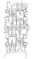
より詳細には、まず図1〜3を見ると、エンジン10は、中央クランクシャフト14の周りに配置された4つのシリンダ12を備え、中央クランクシャフトは軸線z−z(図1を参照)を中心として回転するよう取り付けられている。クランクシャフトの一方の側にあり図1の下側の2つのシリンダは、一方の対向シリンダ対であり、図1の上側の他の2つのシリンダは、他方の対向シリンダ対である。
More specifically, referring first to FIGS. 1-3, the engine 10 includes four
各シリンダ内には内側ピストン16及び外側ピストン18の2つのピストンがある。各シリンダ内の2つのピストンは互いに対向し、この例では180度の位相ずれで反対方向に往復運動する。 Within each cylinder are two pistons, an inner piston 16 and an outer piston 18. The two pistons in each cylinder face each other and in this example reciprocate in opposite directions with a phase shift of 180 degrees.
各ピストンはクラウン20,22と、クラウンから垂下するスカート24,26とを有し、2つのピストンのクラウンは互いに面している。この例では、クラウン24,26は、共に、浅い椀型の形状となっている。上死点において、ピストンクラウンが互いに最も接近する(かつほぼ接触しそうな)とき、対向するクラウン24,26は、燃焼室28を形成する。この燃焼室28では、先立って燃焼室内へ導入された混合気がスパーク点火されて燃焼し、サイクルの動力行程をもたらす。 Each piston has crowns 20 and 22 and skirts 24 and 26 depending from the crowns, the crowns of the two pistons facing each other. In this example, both the crowns 24 and 26 have a shallow saddle shape. At the top dead center, the opposing crowns 24, 26 form a combustion chamber 28 when the piston crowns are closest to each other (and are likely to be in close contact with each other). In the combustion chamber 28, the air-fuel mixture previously introduced into the combustion chamber is ignited and burned, thereby bringing about a cycle power stroke.
以下にさらにより詳細に説明するように、図1の左上のシリンダ及び右下のシリンダに示すように、サイクル内で、ピストンが互いに最も離れて配置され、シリンダ内の最大収容容積(「下死点」)を画定する位置にある場合、ピストンクラウンはシリンダの内側端部及び外側端部それぞれに向かって十分に離れて引き寄せられて、吸気ポート30及び排気ポート32を開く。サイクルの圧縮行程においてピストン16,18が互いに近づく方向に動くと、ピストンスカートがポートを覆って閉じる。内側ピストン16のスカート24は吸気ポート30を閉じ、外側ピストン18のスカート26は排気ポート32を閉じる。図1及び図2において最も良く示されるように、排気ポート32は軸方向の長さ(すなわち、シリンダの長手方向の軸線の方向における寸法)が吸気ポートよりも長いため、排気ポートは吸気ポートよりも早く開き、吸気ポートよりも長く開いたままとなり、シリンダの掃気を助ける。 As will be explained in more detail below, the pistons are located farthest apart from each other in the cycle, as shown in the upper left cylinder and the lower right cylinder in FIG. When in the position defining the point "), the piston crown is pulled sufficiently far towards the inner and outer ends of the cylinder, respectively, to open the intake port 30 and the exhaust port 32. As the pistons 16 and 18 move toward each other during the compression stroke of the cycle, the piston skirt closes over the port. The skirt 24 of the inner piston 16 closes the intake port 30 and the skirt 26 of the outer piston 18 closes the exhaust port 32. As best shown in FIGS. 1 and 2, the exhaust port 32 is longer in the axial direction (ie, the dimension in the direction of the longitudinal axis of the cylinder) than the intake port. It opens earlier and stays open longer than the intake port, helping to scavenge the cylinder.
各シリンダ12には燃料噴射器34が取り付けられている。この副室式の例において、燃料噴射器はシリンダ12の側面に取り付けられ、吸気ポート30に隣接するシリンダ壁を取り囲む環状吸気マニホールド35内へ燃料を噴射する。この例で見られるように、噴射器は、内側ピストン16が吸気ポート30を覆っていないときは、吸気ポート30を介して直接燃料を噴射するように配置することができる。燃料は、従来の方法により噴射器34へ供給される。
A
標準的な噴射器と燃料レールの構成を用いることができる。一部の実施形態では、それぞれのシリンダに複数の噴射器(2、3又はそれ以上の噴射器)を用いることができる。複数の噴射器を用いる際には、シリンダ周りの円周方向に間隔を空けて(好ましくは実質的に等間隔に)使用するものとすることができる。 Standard injector and fuel rail configurations can be used. In some embodiments, multiple injectors (2, 3 or more injectors) can be used for each cylinder. When a plurality of injectors are used, they can be used at intervals in the circumferential direction around the cylinder (preferably at substantially equal intervals).
本発明に従うと、それぞれのシリンダ12は、スパークプラグアッセンブリ36をも備えている。このスパークプラグアセンブリ36は、ハウジング37とハウジング内部に取り付けられたスパークプラグ38とを有しており、スパークプラグ38は、ハウジング37の端部から燃焼室28内へ露出したスパークプラグの電極39を備えている。この例において、スパークプラグ38は、それが固定されたハウジング内で、シリンダ12の中心軸線に沿って取り付けられている。ハウジング37の外側端部はシリンダの外側端部(すなわち、クランクシャフト14と逆側のシリンダの端部)の構成要素40に固定されている。スパークプラグアッセンブリ36が外側ピストンクラウン22の中心開口部42を貫いて延び、スパークプラグ38の内側端部、すなわち、電極39が位置する端部がシリンダ12内の中心に配置される。より具体的には、図2の左下のシリンダ及び右上のシリンダ並びに図1の左側のシリンダにおいて見られるように、ピストン16,18が上死点にある場合、スパークプラグ38の電極39は、直接燃焼室28内の真直中にある。
In accordance with the present invention, each
ここで示されるようにスパークプラグが中心にある配置では、スパークプラグアッセンブリ36は所定の位置に固定されており、エンジン10の動作中、外側ピストン18はスパークプラグハウジング37の外側に沿って移動する。外側ピストンクラウン22の開口部42の周縁部の周りに適切なシール(図示しない)が設けられ、ピストン18がスパークプラグハウジング37に沿って前後に往復運動するときに、ピストンクラウン22とスパークプラグハウジング37との間をシールして、シリンダ内部からの加圧ガスの漏洩を防止又は少なくとも最小限に抑えたり、燃焼室へのオイルの移入を防止する。スパークプラグハウジング37の外面は、ピストン18と摺動可能に接触するよう構成されている。一部の実施例では必要とされないかもしれないが、スパークプラグ38はハウジング37内の冷却液によって囲まれていてもよい。
In the arrangement where the spark plug is centered as shown here, the
スパークプラグ38自体は、従来の構造とすることができる。それらは、従来のコイルにより、電力が供給されてもよい。
The
この例では、スパークプラグアッセンブリ36が外側ピストンを貫通してシリンダの外側端部に突出しているが、他の実施形態では、内側ピストンを貫通して(内側ピストンがスパークプラグハウジング上を摺動して)シリンダの内側端部に突出してもよい。
In this example, the
この例では、ピストン16,18はクランクシャフト14上の各々の偏心輪58に取り付けられた4つのスコッチヨーク配置50,52,54,56を介してクランクシャフト14を駆動する。必要なスコッチヨークの数を最小限にし、クランクシャフトに必要な長さを最小化してよりコンパクトな設計を提供するために、スコッチヨークが複数のピストンによって共有されている。 In this example, the pistons 16, 18 drive the crankshaft 14 through four scotch yoke arrangements 50, 52, 54, 56 attached to each eccentric wheel 58 on the crankshaft 14. In order to minimize the number of scotch yokes required and minimize the length required for the crankshaft and provide a more compact design, the scotch yoke is shared by multiple pistons.
スコッチヨーク配置は、同時係属中の英国特許出願GB1108766.4及びGB1108767.3に示されたものでもよく、これら出願の全内容を本明細書の一部として参照する。具体的には、これら先願の図5及び図6と図に関する記述が、先のスコッチヨーク配置の説明のために参照される。 The scotch yoke arrangement may be that shown in co-pending UK patent applications GB110876.4 and GB110877.3, the entire contents of which are hereby incorporated by reference. Specifically, the descriptions of FIGS. 5 and 6 and the drawings of these prior applications are referred to for the description of the previous Scotch yoke arrangement.
エンジンの動作
図4は、クランクシャフトの1回転における、図1〜3のエンジンの動作を示す。具体的には、図4(a)〜4(m)は、30°刻みのピストン位置を示す。
Engine Operation FIG. 4 shows the operation of the engine of FIGS. 1 to 3 in one rotation of the crankshaft. Specifically, FIGS. 4A to 4M show piston positions in increments of 30 °.
0°ADCの図4(a)は、0°のクランクシャフト位置(ここでは図1の左下側シリンダ12のTDCと定義する)におけるエンジンを示す。この位置において、左下の外側ピストン18c及び左下の内側ピストン16cは最も接近している。クランクシャフトの回転におけるこの角度において、例示の副室式エンジンでは燃焼が継続中であるが、この燃焼は、エンジンの速度や負荷といったエンジン制御パラメータによって、TDCより前の約10°〜40°における点火により開始されている。この時点では、左下のシリンダの排気ポート32及び吸気ポート30は、外側ピストン及び内側ピストンそれぞれによって完全に閉じられている。
FIG. 4 (a) at 0 ° ADC shows the engine at a crankshaft position of 0 ° (here defined as the TDC of the lower
30°ADCの図4(b)では、爆発行程の開始時において、左下のシリンダの内側ピストンと外側ピストンは離れている。 In FIG. 4B of 30 ° ADC, the inner piston and the outer piston of the lower left cylinder are separated at the start of the explosion stroke.
60°ADCの図4(c)では、左下のシリンダは爆発行程を継続し、2つのピストンは等しい速度で逆向きとなる。 In FIG. 4 (c) at 60 ° ADC, the lower left cylinder continues the explosion stroke and the two pistons are reversed at equal speeds.
90°ADCの図4(d)では、左下のシリンダは爆発行程を継続する。 In FIG. 4 (d) at 90 ° ADC, the lower left cylinder continues the explosion stroke.
120°ADCの図4(e)では、左下のシリンダの外側ピストンが排気ポート32を開いている一方、吸気ポートは閉じたままである。この「ブローダウン」状態においては、燃焼室から出る膨張ガスの運動エネルギの一部は、必要であれば、例えば次の圧縮のためのターボチャージャー(「パルス」ターボチャージング)によって、外部で回収することができる。 In FIG. 4E at 120 ° ADC, the outer piston of the lower left cylinder opens the exhaust port 32 while the intake port remains closed. In this “blowdown” state, some of the kinetic energy of the expanded gas exiting the combustion chamber is recovered externally if necessary, for example by a turbocharger for subsequent compression (“pulse” turbocharging). can do.
150°ADCの図4(f)では、左下のシリンダの内側ピストンは吸気ポート30を開いており、シリンダは単流掃気されている。 In FIG. 4F at 150 ° ADC, the inner piston of the lower left cylinder opens the intake port 30, and the cylinder is scavenged by a single flow.
180°ADCの図4(g)では、左下のシリンダの内側ピストン及び外側ピストンが吸気ポート30及び排気ポート32の両方を開いたままにし、単流掃気は継続される。ピストンは下死点にある。 In FIG. 4G at 180 ° ADC, the inner and outer pistons of the lower left cylinder keep both the intake port 30 and the exhaust port 32 open, and single flow scavenging continues. The piston is at bottom dead center.
210°ADCの図4(h)では、左下のシリンダにおいて、ポート30,32の両方が開いたままであり、単流掃気は継続される。燃料は、噴射器から入口マニホールドへ噴射され、噴射器に隣接する吸気ポートを介してシリンダへ運ばれる。 In FIG. 4H of 210 ° ADC, both the ports 30 and 32 remain open in the lower left cylinder, and single flow scavenging is continued. Fuel is injected from the injector into the inlet manifold and carried to the cylinder via an intake port adjacent to the injector.
240°ADCの図4(i)では、左下のシリンダにおいて、内側ピストンは吸気ポート30を閉じている一方で、排気ポート32は一部開いたままである。他の実施形態では、入口ポートが開いた後又は閉じた後に排気ポートが開き、かつ、入口ポートが開く前又は閉じる前に排気ポートが閉じてもよい。あるいは、入口ポートが開いた後又は閉じた後に排気ポートが開くか、又は、入口ポートが開く前又は閉じる前に排気ポートが閉じてもよい。ポートの形状は、新たに供給された空気がシリンダを介して排気管へ移動することなく、良好な掃気を促進するように設計されていることが好ましい。また、いくつかの用途においては、例えば、スリーブバルブを使用してポートの開閉を制御することにより、ポートタイミングが非対称として、排気ポートを図示の例よりも早く閉じるようにすることが望ましい場合がある。また、吸気上昇の適切な制御や調整により、良好な掃気を促すことができる。 In FIG. 4 (i) at 240 ° ADC, in the lower left cylinder, the inner piston closes the intake port 30, while the exhaust port 32 remains partially open. In other embodiments, the exhaust port may open after the inlet port opens or closes, and the exhaust port may close before or before the inlet port opens. Alternatively, the exhaust port may be opened after the inlet port is opened or closed, or the exhaust port may be closed before or before the inlet port is opened. The shape of the port is preferably designed to promote good scavenging without the newly supplied air moving through the cylinder to the exhaust pipe. Also, in some applications, it may be desirable, for example, to use a sleeve valve to control the opening and closing of the port so that the port timing is asymmetric and the exhaust port closes earlier than the illustrated example. is there. Moreover, good scavenging can be promoted by appropriate control and adjustment of the intake air rise.
270°ADCの図4(j)では、左下のシリンダにおいて、外側ピストンは排気ポート32を閉じており、2つのピストンは互いに近づいており、それらの間の混合気を圧縮している。 In FIG. 4 (j) at 270 ° ADC, in the lower left cylinder, the outer piston closes the exhaust port 32, and the two pistons are close to each other, compressing the mixture between them.
300°ADCの図4(k)では、左下のシリンダにおいて、ピストンは圧縮行程を継続している。 In FIG. 4 (k) of 300 ° ADC, the piston continues the compression stroke in the lower left cylinder.
330°ADCの図4(l)では、左下のシリンダは圧縮行程の終了に近づいている。 In FIG. 4 (l) at 330 ° ADC, the lower left cylinder is approaching the end of the compression stroke.
360°ADCの図4(m)では、位置は図3(a)と同じである。左下のシリンダがTDC位置に達しており、外側と内側のピストンは最も接近している。 In FIG. 4 (m) of 360 ° ADC, the position is the same as in FIG. 3 (a). The lower left cylinder has reached the TDC position, and the outer and inner pistons are closest.
特定の角度及びタイミングは、クランクシャフトの配置や、ポートのサイズ及び位置に依存する。上記は単に本発明の概念を示すことを意図するものである。吸気マニホールドへの燃料供給のタイミングは、エンジンの特性と、その制御パラメータに基づく従来の方法で決定することができる。 The particular angle and timing depends on the crankshaft arrangement and the port size and position. The above is merely intended to illustrate the concept of the present invention. The timing of fuel supply to the intake manifold can be determined by a conventional method based on the characteristics of the engine and its control parameters.
変形例
図5〜9は、本発明のさらなる代表的な実施形態を示す。これらの動作は、上述した実施形態と概ね類似している。これらは、下記で説明されるように、上述した実施形態とは、スパークプラグ及び燃料噴射器の両方又はいずれか一方の形状と配置が異なっている。
Variations FIGS. 5-9 show further exemplary embodiments of the present invention. These operations are generally similar to the above-described embodiment. As described below, these are different from the above-described embodiment in the shape and arrangement of either or both of the spark plug and the fuel injector.
図5は、他の副室式の構成を示す。燃料噴射器34は、図1〜4の実施形態と同様に構成され動作する。しかしながら、この例では、スパークプラグ38は外側ピストン18に固定され、外側ピストンと共に動く。他の実施形態では、スパークプラグ38を内側ピストン16に固定して、内側ピストンと共に動くようにしてもよい。
FIG. 5 shows another sub-chamber type configuration. The
スパークプラグ38に電力を供給するために、摺動電気コネクタ60がスパークプラグ38の外端に取り付けられている。
A sliding electrical connector 60 is attached to the outer end of the
図6は、直噴エンジンの4つの変形例のうちの最初のものを示す。この例では、燃料噴射器34は、シリンダ12の壁の定位置にある。必要に応じて、複数の噴射器がシリンダの周りに円周方向に間隔を空けて配置されてもよい。噴射ノズルはシリンダ内に直接露出しており、(図6の左側シリンダにみられるように)ピストン同士が最も接近したときに形成される燃焼室と直列となっている。排気ポートが閉じた後、かつ、TDCの前の所定の時点で、燃料がシリンダ内へ直接噴射される。混合気はスパークプラグ38により点火される。この例では、スパークプラグの構成は、図1〜4の実施形態について上述したものと同様である。
FIG. 6 shows the first of four variations of a direct injection engine. In this example, the
図7は、別の直噴の例を示す。しかしながら、この例では、燃料噴射器34は、スパークプラグ38と並んで取り付けられており、シリンダの一端(図示の例では、外側端部)から延びて、シリンダと同軸上にある。噴射器34とスパークプラグは、この例では同じハウジング37に設けられており、このハウジング内の冷却剤により冷却されてもよい。この例では、スパークプラグと噴射器が結合したアッセンブリが、外側ピストンに取り付けられているが、他の実施形態では、アッセンブリは、内側ピストンを貫通してシリンダの内側の端部から突き出るようにすることもできる。
FIG. 7 shows another example of direct injection. However, in this example, the
図8に見られる変形例は、内側ピストンに固定され、内側ピストンと共に動くスパークプラグ38を有している。図5に見られる変形例と同様に、摺動電気コネクタ60はスパークプラグ38に電力を供給するために用いられる。この例の燃料噴射器34は、シリンダ内中央の定位置に取り付けられており、外側ピストン18を貫通してシリンダの外側端部から延びている。外側ピストン18は、燃料噴射器のハウジングに沿って摺動する。それゆえに、この例では、燃料噴射器34のノズルは、スパークプラグ38の電極と対向しており、ピストン同士が最も接近するときに、互いに接近して対向する(図8の左側のシリンダ参照)。
The variant seen in FIG. 8 has a
図9は、図8のものに類似した変形例を示している(スパークプラグ38の構成は同様である)が、燃料噴射器34は、シリンダ内の定位置に固定されるのではなく、外側ピストン18に固定され、外側ピストン18と共に動く。図8の例と同様に、ピストンが互いに最も接近する位置にあるとき、スパークプラグの電極と噴射器のノズルは、シリンダの中心線上で互いに接近して対向する(図9の左側のシリンダ参照)。他の実施形態では、燃料噴射器34とスパークプラグ38との位置を逆にして、スパークプラグ38が外側ピストン18と共に動き、燃料噴射器が内側ピストン16と共に動くようにしてもよい。
FIG. 9 shows a variation similar to that of FIG. 8 (the configuration of the
図5〜9は、数多の考え得る変形例のうちのいくつかを示しており、これら説明した変形例の特徴は、特に説明されていない他の組み合わせにおいて、互いに用いてもよい。例えば、図8における動くスパークプラグの配置を、図6に見られる、シリンダの側壁内に直噴の噴射器を固定した配置と共に用いてもよいし、図1及び5に見られる、間接的な噴射器の配置と共に用いてもよい。他の組み合わせも可能である。 FIGS. 5-9 illustrate some of the many possible variations, and the features of these variations described may be used with each other in other combinations not specifically described. For example, the moving spark plug arrangement in FIG. 8 may be used with the arrangement shown in FIG. 6 with a direct injection injector fixed in the side wall of the cylinder, or the indirect arrangement seen in FIGS. You may use with the arrangement | positioning of an injector. Other combinations are possible.
当業者であれば、具体的に記載した実施形態の種々の変形が本発明から逸脱することなく可能であることを理解するであろう。例えば、本発明は、2ストロークスパーク点火エンジンという文脈で示されているが、本発明の実施形態は2ストロークであっても4ストロークであってもよく、スパーク点火であってもスパーク補助エンジンタイプであってもよいということも、当業者は理解するであろう。
Those skilled in the art will appreciate that various modifications of the specifically described embodiments are possible without departing from the invention. For example, although the present invention is shown in the context of a two-stroke spark ignition engine, embodiments of the present invention may be two-stroke or four-stroke, and may be spark-ignited with a spark auxiliary engine type. Those skilled in the art will also understand that it may be.
Claims (17)
前記シリンダ内の対向する往復動ピストンの対であって、それらの間に燃焼室を形成するピストンの対と、
前記シリンダに取り付けられた少なくとも1つの燃焼点火装置であって、前記対向するピストンの間に形成される前記燃焼室内にその一部が露出する燃焼点火装置とを備え、
前記燃焼点火装置は、前記シリンダの一端において固定されており、かつその端部から前記シリンダ内に、前記シリンダの中心軸線に沿って又は平行して突出し、エンジンのサイクルを通して、前記燃焼点火装置の前記突出部分が前記燃焼室内の定位置に配置される内燃機関。 At least one cylinder;
A pair of opposing reciprocating pistons in the cylinder, the pair of pistons forming a combustion chamber therebetween;
At least one combustion ignition device attached to the cylinder, the combustion ignition device having a part thereof exposed in the combustion chamber formed between the opposed pistons ;
The combustion igniter is fixed at one end of the cylinder, and projects from the end into the cylinder along or parallel to the central axis of the cylinder. Through the engine cycle, the combustion igniter An internal combustion engine in which the protruding portion is disposed at a fixed position in the combustion chamber .
前記シリンダ内の対向する往復動ピストンの対であって、それらの間に燃焼室を形成するピストンの対と、
前記シリンダに取り付けられた少なくとも1つの燃焼点火装置であって、前記対向するピストンの間に形成される前記燃焼室内にその一部が露出する燃焼点火装置と、
前記シリンダ内へ直接燃料を噴射するために、前記燃焼室に直接露出する噴射ノズルを有する少なくとも1つの燃料噴射器とを備え、
前記少なくとも1つの燃料噴射器は、前記シリンダの一端に取り付けられており、前記噴射ノズルが、前記シリンダの一端でそれぞれのピストンクラウンを貫通して前記燃焼室内に突出している内燃機関。 At least one cylinder;
A pair of opposing reciprocating pistons in the cylinder, the pair of pistons forming a combustion chamber therebetween;
At least one combustion ignition device attached to the cylinder, the combustion ignition device having a part thereof exposed in the combustion chamber formed between the opposed pistons;
At least one fuel injector having an injection nozzle directly exposed to the combustion chamber for injecting fuel directly into the cylinder;
Wherein the at least one fuel injector is attached to one end of said cylinder, said injection nozzle, the inner combustion engine that protrude into the combustion chamber through the respective piston crown at one end of said cylinder.
Applications Claiming Priority (3)
| Application Number | Priority Date | Filing Date | Title |
|---|---|---|---|
| GBGB1122432.6A GB201122432D0 (en) | 2011-12-23 | 2011-12-23 | Internal combustion engines |
| GB1122432.6 | 2011-12-23 | ||
| PCT/GB2012/053238 WO2013093501A1 (en) | 2011-12-23 | 2012-12-21 | Internal combustion engines |
Publications (3)
| Publication Number | Publication Date |
|---|---|
| JP2015502493A JP2015502493A (en) | 2015-01-22 |
| JP2015502493A5 JP2015502493A5 (en) | 2015-12-17 |
| JP6125533B2 true JP6125533B2 (en) | 2017-05-10 |
Family
ID=45695061
Family Applications (1)
| Application Number | Title | Priority Date | Filing Date |
|---|---|---|---|
| JP2014548203A Expired - Fee Related JP6125533B2 (en) | 2011-12-23 | 2012-12-21 | Internal combustion engine |
Country Status (11)
| Country | Link |
|---|---|
| US (1) | US10458323B2 (en) |
| EP (1) | EP2805016B1 (en) |
| JP (1) | JP6125533B2 (en) |
| KR (1) | KR20140108692A (en) |
| CN (1) | CN104145082B (en) |
| DK (1) | DK2805016T3 (en) |
| ES (1) | ES2680647T3 (en) |
| GB (1) | GB201122432D0 (en) |
| IL (1) | IL233316B (en) |
| PT (1) | PT2805016T (en) |
| WO (1) | WO2013093501A1 (en) |
Families Citing this family (5)
| Publication number | Priority date | Publication date | Assignee | Title |
|---|---|---|---|---|
| US9581024B2 (en) * | 2014-05-21 | 2017-02-28 | Achates Power, Inc. | Air handling constructions for opposed-piston engines |
| US9551220B2 (en) | 2014-05-21 | 2017-01-24 | Achates Power, Inc. | Open intake and exhaust chamber constructions for an air handling system of an opposed-piston engine |
| WO2021081591A1 (en) * | 2019-10-29 | 2021-05-06 | ASF Technologies (Australia) Pty Ltd | Internal combustion engine having targeted engine lubrication |
| EP4051875A4 (en) * | 2019-10-29 | 2023-09-27 | ASF Technologies (Australia) Pty Ltd | Internal combustion engine having concentric camshaft and balance shaft |
| US20230349319A1 (en) * | 2022-05-02 | 2023-11-02 | Enginuity Power Systems, Inc. | Multi-fuel engines and related methods |
Family Cites Families (24)
| Publication number | Priority date | Publication date | Assignee | Title |
|---|---|---|---|---|
| US1270295A (en) * | 1915-04-26 | 1918-06-25 | Allan S Husted | Internal-combustion engine. |
| US2213817A (en) * | 1939-04-03 | 1940-09-03 | Walter T Kinslow | Internal expansion engine |
| GB1108766A (en) | 1965-05-11 | 1968-04-03 | Bielefelder Union Koch | Panel edge grinding machine |
| BE670579A (en) | 1965-08-05 | |||
| DE3940027A1 (en) | 1989-12-04 | 1990-08-23 | Harry Steinke | Opposed piston two=stroke IC engine - uses supercharged air supply and fuel injection into cylinders |
| BG62787B1 (en) | 1997-02-04 | 2000-07-31 | Георги ГЪЛЪБОВ | Internal combustion piston engine |
| US7121235B2 (en) | 1997-09-02 | 2006-10-17 | Walter Schmied | Reciprocating internal combustion engine |
| US6170443B1 (en) * | 1998-09-11 | 2001-01-09 | Edward Mayer Halimi | Internal combustion engine with a single crankshaft and having opposed cylinders with opposed pistons |
| JP2001227356A (en) * | 2000-02-12 | 2001-08-24 | Takayuki Kikumori | Double piston engine |
| JP2005009471A (en) * | 2003-06-21 | 2005-01-13 | Shogo Tsuchida | Multidirectional type cylinder |
| EP1639243B1 (en) * | 2003-06-25 | 2016-04-27 | Peter Hofbauer | Internal combustion engine |
| US7255071B2 (en) * | 2004-03-17 | 2007-08-14 | Beshore Craig S | Supercharged two-stroke engine with upper piston extensions |
| JP2006056805A (en) | 2004-08-18 | 2006-03-02 | Senmi Ekisu Co Ltd | Calcium channel inhibitor |
| GB2428450B (en) | 2005-07-15 | 2007-08-01 | Lotus Car | Opposed piston engine with variable timing |
| US7448352B2 (en) * | 2005-10-31 | 2008-11-11 | Warren James C | Centrally located ignition source in a combustion chamber |
| NL1031165C2 (en) * | 2006-02-16 | 2007-08-17 | Jacob Arnold Hendrik Fr Jaquet | Internal combustion engine with variable compression ratio. |
| US7559298B2 (en) | 2006-04-18 | 2009-07-14 | Cleeves Engines Inc. | Internal combustion engine |
| US7520251B2 (en) * | 2006-05-01 | 2009-04-21 | Saari Robert S | Non-reciprocating internal combustion engine |
| US7434550B2 (en) * | 2006-06-13 | 2008-10-14 | Advanced Propulsion Technologies, Inc. | Internal combustion engine |
| GB0710852D0 (en) * | 2007-06-06 | 2007-07-18 | Cox Powertrain Ltd | Internal combustion engines |
| JP2009197737A (en) * | 2008-02-22 | 2009-09-03 | Katsuhito Yokouchi | Internal combustion engine |
| ITMI20080597A1 (en) | 2008-04-07 | 2009-10-08 | Ernestino Marchesi | INTERNAL COMBUSTION ENGINE, PARTICULARLY FOR KART, MOTORCYCLES, MOTOR VEHICLES IN GENERAL. |
| US7984702B2 (en) | 2008-06-20 | 2011-07-26 | Russell Energy Corporation | Plug-in-piston assembly and method of using the same |
| TWI407008B (en) * | 2009-05-20 | 2013-09-01 | Tai Shan Chao | Intake and exhaust disc piston two-stroke three-cylinder petrol engine |
-
2011
- 2011-12-23 GB GBGB1122432.6A patent/GB201122432D0/en not_active Ceased
-
2012
- 2012-12-21 WO PCT/GB2012/053238 patent/WO2013093501A1/en active Application Filing
- 2012-12-21 US US14/368,284 patent/US10458323B2/en not_active Expired - Fee Related
- 2012-12-21 EP EP12812709.9A patent/EP2805016B1/en active Active
- 2012-12-21 JP JP2014548203A patent/JP6125533B2/en not_active Expired - Fee Related
- 2012-12-21 CN CN201280069576.2A patent/CN104145082B/en not_active Expired - Fee Related
- 2012-12-21 ES ES12812709.9T patent/ES2680647T3/en active Active
- 2012-12-21 PT PT128127099T patent/PT2805016T/en unknown
- 2012-12-21 DK DK12812709.9T patent/DK2805016T3/en active
- 2012-12-21 KR KR1020147020151A patent/KR20140108692A/en not_active Application Discontinuation
-
2014
- 2014-06-23 IL IL233316A patent/IL233316B/en active IP Right Grant
Also Published As
| Publication number | Publication date |
|---|---|
| EP2805016A1 (en) | 2014-11-26 |
| JP2015502493A (en) | 2015-01-22 |
| IL233316B (en) | 2018-10-31 |
| IL233316A0 (en) | 2014-08-31 |
| CN104145082A (en) | 2014-11-12 |
| KR20140108692A (en) | 2014-09-12 |
| US10458323B2 (en) | 2019-10-29 |
| CN104145082B (en) | 2021-07-09 |
| ES2680647T3 (en) | 2018-09-10 |
| GB201122432D0 (en) | 2012-02-08 |
| EP2805016B1 (en) | 2018-05-16 |
| PT2805016T (en) | 2018-07-30 |
| DK2805016T3 (en) | 2018-08-06 |
| US20150027418A1 (en) | 2015-01-29 |
| WO2013093501A1 (en) | 2013-06-27 |
Similar Documents
| Publication | Publication Date | Title |
|---|---|---|
| EP2721256B1 (en) | Internal combustion engines | |
| US7516723B2 (en) | Double piston cycle engine | |
| JP3016485B2 (en) | Reciprocating 2-cycle internal combustion engine without crank | |
| JP6125533B2 (en) | Internal combustion engine | |
| US9951679B2 (en) | Reciprocating internal combustion engine | |
| US20140196693A1 (en) | Internal combustion engines | |
| KR102219792B1 (en) | Internal combustion engines | |
| JPS63295821A (en) | Internal combustion engine |
Legal Events
| Date | Code | Title | Description |
|---|---|---|---|
| A521 | Request for written amendment filed |
Free format text: JAPANESE INTERMEDIATE CODE: A523 Effective date: 20151028 |
|
| A621 | Written request for application examination |
Free format text: JAPANESE INTERMEDIATE CODE: A621 Effective date: 20151028 |
|
| A131 | Notification of reasons for refusal |
Free format text: JAPANESE INTERMEDIATE CODE: A131 Effective date: 20160913 |
|
| A601 | Written request for extension of time |
Free format text: JAPANESE INTERMEDIATE CODE: A601 Effective date: 20161207 |
|
| A521 | Request for written amendment filed |
Free format text: JAPANESE INTERMEDIATE CODE: A523 Effective date: 20170207 |
|
| TRDD | Decision of grant or rejection written | ||
| A01 | Written decision to grant a patent or to grant a registration (utility model) |
Free format text: JAPANESE INTERMEDIATE CODE: A01 Effective date: 20170314 |
|
| A61 | First payment of annual fees (during grant procedure) |
Free format text: JAPANESE INTERMEDIATE CODE: A61 Effective date: 20170405 |
|
| R150 | Certificate of patent or registration of utility model |
Ref document number: 6125533 Country of ref document: JP Free format text: JAPANESE INTERMEDIATE CODE: R150 |
|
| R250 | Receipt of annual fees |
Free format text: JAPANESE INTERMEDIATE CODE: R250 |
|
| R250 | Receipt of annual fees |
Free format text: JAPANESE INTERMEDIATE CODE: R250 |
|
| R250 | Receipt of annual fees |
Free format text: JAPANESE INTERMEDIATE CODE: R250 |
|
| LAPS | Cancellation because of no payment of annual fees |