JP6119155B2 - Light control device, image display device, light control method and program - Google Patents
Light control device, image display device, light control method and program Download PDFInfo
- Publication number
- JP6119155B2 JP6119155B2 JP2012206082A JP2012206082A JP6119155B2 JP 6119155 B2 JP6119155 B2 JP 6119155B2 JP 2012206082 A JP2012206082 A JP 2012206082A JP 2012206082 A JP2012206082 A JP 2012206082A JP 6119155 B2 JP6119155 B2 JP 6119155B2
- Authority
- JP
- Japan
- Prior art keywords
- image
- aperture ratio
- light
- dimming
- image signal
- Prior art date
- Legal status (The legal status is an assumption and is not a legal conclusion. Google has not performed a legal analysis and makes no representation as to the accuracy of the status listed.)
- Active
Links
Images


Classifications
-
- G—PHYSICS
- G09—EDUCATION; CRYPTOGRAPHY; DISPLAY; ADVERTISING; SEALS
- G09G—ARRANGEMENTS OR CIRCUITS FOR CONTROL OF INDICATING DEVICES USING STATIC MEANS TO PRESENT VARIABLE INFORMATION
- G09G3/00—Control arrangements or circuits, of interest only in connection with visual indicators other than cathode-ray tubes
- G09G3/20—Control arrangements or circuits, of interest only in connection with visual indicators other than cathode-ray tubes for presentation of an assembly of a number of characters, e.g. a page, by composing the assembly by combination of individual elements arranged in a matrix no fixed position being assigned to or needed to be assigned to the individual characters or partial characters
- G09G3/34—Control arrangements or circuits, of interest only in connection with visual indicators other than cathode-ray tubes for presentation of an assembly of a number of characters, e.g. a page, by composing the assembly by combination of individual elements arranged in a matrix no fixed position being assigned to or needed to be assigned to the individual characters or partial characters by control of light from an independent source
- G09G3/3406—Control of illumination source
-
- G—PHYSICS
- G09—EDUCATION; CRYPTOGRAPHY; DISPLAY; ADVERTISING; SEALS
- G09G—ARRANGEMENTS OR CIRCUITS FOR CONTROL OF INDICATING DEVICES USING STATIC MEANS TO PRESENT VARIABLE INFORMATION
- G09G2320/00—Control of display operating conditions
- G09G2320/02—Improving the quality of display appearance
- G09G2320/0285—Improving the quality of display appearance using tables for spatial correction of display data
-
- G—PHYSICS
- G09—EDUCATION; CRYPTOGRAPHY; DISPLAY; ADVERTISING; SEALS
- G09G—ARRANGEMENTS OR CIRCUITS FOR CONTROL OF INDICATING DEVICES USING STATIC MEANS TO PRESENT VARIABLE INFORMATION
- G09G2320/00—Control of display operating conditions
- G09G2320/06—Adjustment of display parameters
- G09G2320/0626—Adjustment of display parameters for control of overall brightness
- G09G2320/0646—Modulation of illumination source brightness and image signal correlated to each other
-
- G—PHYSICS
- G09—EDUCATION; CRYPTOGRAPHY; DISPLAY; ADVERTISING; SEALS
- G09G—ARRANGEMENTS OR CIRCUITS FOR CONTROL OF INDICATING DEVICES USING STATIC MEANS TO PRESENT VARIABLE INFORMATION
- G09G2360/00—Aspects of the architecture of display systems
- G09G2360/16—Calculation or use of calculated indices related to luminance levels in display data
Description
本発明は、調光制御装置、画像表示装置、調光制御方法及びプログラムに関する。 The present invention relates to a light control device, an image display device, a light control method, and a program.
表示装置の一態様として、液晶ライトバルブを用いた光学系から射出される映像を投射レンズによりスクリーンに拡大投射する投射型表示装置(液晶プロジェクタ)が知られている。
しかし、このような投射型表示装置は、光学系を構成する各種の光学要素で生じる光漏れや迷光のために充分なコントラストが得られにくいという問題を有している。このような問題を解決するには、例えば画像信号に応じて液晶ライトバルブに入射させる光量を変更すればよい。しかし、現状において投射型表示装置に使用される光源としては、高圧水銀ランプが主流であり、この高圧水銀ランプ自体の光出力強度を制御するのは極めて困難な状況にある。
また、このように光源の明るさが固定されていることにより、例えば暗めの鑑賞環境においては画面が明るくなりすぎたり、ズーミングなどにより投射映像のサイズを変化させたりした場合に画面の明るさが変化してしまうという問題も生じている。
As one mode of a display device, a projection display device (liquid crystal projector) that enlarges and projects an image emitted from an optical system using a liquid crystal light valve onto a screen by a projection lens is known.
However, such a projection display device has a problem that it is difficult to obtain sufficient contrast due to light leakage and stray light generated in various optical elements constituting the optical system. In order to solve such a problem, for example, the amount of light incident on the liquid crystal light valve may be changed according to the image signal. However, as a light source used in the projection display device at present, a high-pressure mercury lamp is mainly used, and it is extremely difficult to control the light output intensity of the high-pressure mercury lamp itself.
In addition, since the brightness of the light source is fixed in this way, for example, in a dark appreciation environment, the screen becomes bright when the screen becomes too bright or the size of the projected image is changed by zooming or the like. There is also the problem of changing.
そこで、投射型表示装置用の照明装置として、光源に対して調光用のルーバー(遮光板)を組み合わせた構造の調光素子を備え、画像信号に応じて、この調光素子により光源からの射出光についての遮光量を変更するように制御するという構成が提案されている。これにより、光源とは別の調光素子により光源から射出された光の光量の変更を高速かつ高い自由度で行うことができる(例えば、特許文献1参照)。 Therefore, as a lighting device for a projection display device, a light control element having a structure in which a light control louver (light shielding plate) is combined with a light source is provided. A configuration has been proposed in which control is performed so as to change the light shielding amount of the emitted light. Thereby, the light quantity of the light emitted from the light source by the dimming element different from the light source can be changed at high speed and with a high degree of freedom (see, for example, Patent Document 1).
しかし、上記のように遮光板を備えた調光素子による調光制御を行った場合には、減光量が多いほど表示画像における色むらが生じやすい。
液晶プロジェクタにおいては、光源から射出された光の光軸に直交する面に沿うようにフライアレイレンズが設けられる。このフライアレイレンズによって光源から射出された光が複数の光束に分割され、これにより、液晶ライトバルブに入射する光の照度分布が均一化される。
遮光板を備えた調光素子により減光量を多くしていくことによっては、フライアレイレンズにおいて光が透過するレンズのセルが少なくなるのであるが、これがスクリーンに表示される画像における色むらを生じさせる要因となっている。
However, when the dimming control is performed by the dimming element including the light shielding plate as described above, the color unevenness in the display image is more likely to occur as the light reduction amount increases.
In a liquid crystal projector, a fly array lens is provided along a plane orthogonal to the optical axis of light emitted from a light source. The light emitted from the light source by the fly array lens is divided into a plurality of light fluxes, so that the illuminance distribution of the light incident on the liquid crystal light valve is made uniform.
Increasing the amount of light reduction with a light control element equipped with a light-shielding plate reduces the number of lens cells through which light passes through the fly array lens. It is a factor to make.
本発明は、このような事情に鑑みてなされたもので、遮光板を備える調光素子を利用した調光制御を行って画像表示を行うにあたり、表示される画像の色むらが抑制されるようにすることを目的とする。 The present invention has been made in view of such circumstances, and color unevenness of a displayed image is suppressed in performing image dimming control using a dimming element including a light shielding plate. The purpose is to.
上述した課題を解決するために、本発明の一態様としての調光制御装置は、画像信号の画像特徴量に基づいて、前記画像信号に基づく画像が調光補正対象であるか否かについて判定する画像判定部と、画像表示のために光源から射出された光を遮断する調光素子の開口部の開口率を画像信号に基づいて設定するにあたり、前記画像信号に基づく画像が調光補正対象であると判定された場合には、前記画像信号に基づく画像が調光補正対象ではないと判定された場合に応じて設定する基礎の開口率を補正した開口率を設定する開口率設定部と、前記開口率設定部により設定された開口率に基づいて前記調光素子を制御することにより、画像表示のために光源から射出された光の光量を変更する調光制御部とを備える。 In order to solve the above-described problem, a dimming control device according to one aspect of the present invention determines whether an image based on the image signal is a dimming correction target based on an image feature amount of the image signal. When setting the aperture ratio of the image determination unit that performs the aperture of the dimming element that blocks light emitted from the light source for image display based on the image signal, the image based on the image signal is subject to dimming correction An aperture ratio setting unit that sets an aperture ratio obtained by correcting a basic aperture ratio that is set when it is determined that the image based on the image signal is not a dimming correction target; And a dimming control unit that controls the dimming element based on the aperture ratio set by the aperture ratio setting unit to change the amount of light emitted from the light source for image display.
この構成により、画像信号に基づく画像が例えば色むらなどのように光源からの光量の減少に起因する画質劣化が目立つような画像であると判定されるのに応じて、調光素子において光源からの光の光量を変更するための開口部の開口率が変更されるように制御される。これにより、遮光板を備える調光素子を利用した調光制御を行って画像表示を行うにあたり、表示される画像の画質劣化を抑制することが可能となる。 With this configuration, when the image based on the image signal is determined to be an image in which deterioration in image quality due to a decrease in the amount of light from the light source such as color unevenness is conspicuous, Control is performed so that the aperture ratio of the opening for changing the light quantity of the light is changed. Thus, when performing image display by performing light control using a light control element including a light shielding plate, it is possible to suppress deterioration in image quality of the displayed image.
また、本発明の調光制御装置において、前記画像判定部は、前記画像信号に基づく画像が画面において同じ輝度が一様に分布するラスター画像であると判定した場合に調光補正対象であると判定してもよい。 Further, in the dimming control device of the present invention, the image determination unit is a dimming correction target when it is determined that the image based on the image signal is a raster image in which the same luminance is uniformly distributed on the screen. You may judge.
この構成により、光源からの光量減少に起因する画質劣化が目立つラスター画像が表示される際には、補正された開口率に基づいて調光が行われる。これにより、ラスター画像が表示される際の画質劣化が抑制される。 With this configuration, when a raster image in which image quality deterioration due to a decrease in the amount of light from the light source is conspicuous is displayed, dimming is performed based on the corrected aperture ratio. Thereby, image quality degradation when a raster image is displayed is suppressed.
また、本発明の調光制御装置において、前記画像判定部は、前記画像特徴量の1つであるフレームにおける各画素の輝度値のうちの最大値である白ピーク値と、前記画像特徴量の1つであるフレームにおける輝度の平均値との差分が一定値以内である場合に、前記画像信号に基づく画像がラスター画像であると判定してもよい。 In the dimming control device according to the aspect of the invention, the image determination unit may include a white peak value that is a maximum value of luminance values of each pixel in a frame that is one of the image feature amounts, and the image feature amount. When the difference from the average luminance value in one frame is within a certain value, it may be determined that the image based on the image signal is a raster image.
この構成により、画像特徴量における白ピーク値とフレームにおける輝度の平均値とがほぼ同じである場合にラスター画像であると判定することができる。これにより、ラスター画像であるか否かについて的確に判定することが可能となる。 With this configuration, it is possible to determine that the image is a raster image when the white peak value in the image feature amount and the average value of the luminance in the frame are substantially the same. This makes it possible to accurately determine whether or not the image is a raster image.
また、本発明の調光制御装置において、前記画像判定部は、前記画像特徴量の1つである輝度ヒストグラムにおいてデータ数が最大の階級を含む一定範囲の階級に全データのうちの一定比率以上のデータが存在する場合に、前記画像信号に基づく画像がラスター画像であると判定してもよい。 In the dimming control device according to the aspect of the invention, the image determination unit may have a certain ratio or more of all data in a certain range of classes including the class having the maximum number of data in the luminance histogram that is one of the image feature amounts. May be determined as an image based on the image signal.
この構成により、画像特徴量としての輝度ヒストグラムが、特定の1つの階級にほぼすべてのデータが存在しているという特徴を有する場合にラスター画像であると判定することができる。これにより、ラスター画像であるか否かについて的確に判定することが可能となる。 With this configuration, it is possible to determine that the image is a raster image when the luminance histogram as the image feature amount has a characteristic that almost all data exists in one specific class. This makes it possible to accurately determine whether or not the image is a raster image.
また、本発明の調光制御装置において、前記画像判定部は、前記画像信号に基づく画像がモノクローム画像であると判定した場合に調光補正対象であると判定してもよい。 In the dimming control device of the present invention, the image determination unit may determine that the image based on the image signal is a dimming correction target when it is determined that the image is a monochrome image.
この構成により、光源からの光量減少に起因する画質劣化が目立つモノクローム画像が表示される際には、補正された開口率に基づいて調光が行われる。これにより、モノクローム画像が表示される際の画質劣化が抑制される。 With this configuration, when a monochrome image in which image quality deterioration due to a reduction in the amount of light from the light source is conspicuous is displayed, dimming is performed based on the corrected aperture ratio. Thereby, image quality deterioration when a monochrome image is displayed is suppressed.
また、本発明の調光制御装置において、前記画像判定部は、前記画像特徴量の1つである彩度ヒストグラムにおいて彩度がゼロの階級を含む一定範囲の階級に全データのうちの一定比率以上のデータが存在する場合に、前記画像信号に基づく画像がモノクローム画像であると判定してよい。 In the dimming control device according to the aspect of the invention, the image determination unit may include a certain ratio of all data in a certain range of classes including a class having a saturation of zero in a saturation histogram that is one of the image feature values. When the above data exists, it may be determined that the image based on the image signal is a monochrome image.
この構成により、画像特徴量としての彩度ヒストグラムが、ゼロの階級にほぼすべてのデータが存在しているという特徴を有する場合にモノクローム画像であると判定することができる。これにより、モノクローム画像であるか否かについて的確に判定することが可能となる。 With this configuration, it is possible to determine that the image is a monochrome image when the saturation histogram as the image feature amount has a feature that almost all data exists in the zero class. This makes it possible to accurately determine whether the image is a monochrome image.
また、本発明の一態様としての画像表示装置は、上記の調光制御装置と、前記調光素子を含み、前記調光制御装置により光量が変更された光により画像信号を投射画像として表示する光学系部とを備える。 An image display device according to an aspect of the present invention includes the light control device described above and the light control element, and displays an image signal as a projection image by light whose light amount has been changed by the light control device. An optical system unit.
この構成により、画像信号に基づく画像が例えば色むらなどのように光源からの光量の減少に起因する画質劣化が目立つような画像であると判定されるのに応じて、調光素子において光源からの光の光量を変更するための開口部の開口率が変更されるように制御される。これにより、遮光板を備える調光素子を利用した調光制御を行って画像表示を行うにあたり、表示される画像の画質劣化を抑制することが可能となる。 With this configuration, when the image based on the image signal is determined to be an image in which deterioration in image quality due to a decrease in the amount of light from the light source such as color unevenness is conspicuous, Control is performed so that the aperture ratio of the opening for changing the light quantity of the light is changed. Thus, when performing image display by performing light control using a light control element including a light shielding plate, it is possible to suppress deterioration in image quality of the displayed image.
また、本発明の一態様としての調光制御方法は、画像信号の画像特徴量に基づいて、前記画像信号に基づく画像が調光補正対象であるか否かについて判定する画像判定ステップと、画像表示のために光源から射出された光を遮断する調光素子の開口部の開口率を画像信号に基づいて設定するにあたり、前記画像信号に基づく画像が調光補正対象であると判定された場合には、前記画像信号に基づく画像が調光補正対象ではないと判定された場合に応じて設定する基礎の開口率を補正した開口率を設定する開口率設定ステップと、前記開口率設定ステップにより設定された開口率に基づいて前記調光素子を制御することにより、画像表示のために光源から射出された光の光量を変更する調光制御ステップとを備える。 Further, the dimming control method as one aspect of the present invention includes an image determination step for determining whether an image based on the image signal is a dimming correction target based on an image feature amount of the image signal; When setting the aperture ratio of the opening of the dimming element that blocks light emitted from the light source for display based on the image signal, it is determined that the image based on the image signal is a dimming correction target Includes an aperture ratio setting step for setting an aperture ratio obtained by correcting a basic aperture ratio to be set when it is determined that an image based on the image signal is not a dimming correction target, and the aperture ratio setting step. A dimming control step of changing the amount of light emitted from the light source for image display by controlling the dimming element based on the set aperture ratio.
この構成により、画像信号に基づく画像が例えば色むらなどのように光源からの光量の減少に起因する画質劣化が目立つような画像であると判定されるのに応じて、調光素子において光源からの光の光量を変更するための開口部の開口率が変更されるように制御される。これにより、遮光板を備える調光素子を利用した調光制御を行って画像表示を行うにあたり、表示される画像の画質劣化を抑制することが可能となる。 With this configuration, when the image based on the image signal is determined to be an image in which deterioration in image quality due to a decrease in the amount of light from the light source such as color unevenness is conspicuous, Control is performed so that the aperture ratio of the opening for changing the light quantity of the light is changed. Thus, when performing image display by performing light control using a light control element including a light shielding plate, it is possible to suppress deterioration in image quality of the displayed image.
また、本発明の一態様としてのプログラムは、コンピュータに、画像信号の画像特徴量に基づいて、前記画像信号に基づく画像が調光補正対象であるか否かについて判定する画像判定ステップと、画像表示のために光源から射出された光を遮断する調光素子の開口部の開口率を画像信号に基づいて設定するにあたり、前記画像信号に基づく画像が調光補正対象であると判定された場合には、前記画像信号に基づく画像が調光補正対象ではないと判定された場合に応じて設定する基礎の開口率を補正した開口率を設定する開口率設定ステップと、前記開口率設定ステップにより設定された開口率に基づいて前記調光素子を制御することにより、画像表示のために光源から射出された光の光量を変更する調光制御ステップとを実行させるためのものである。 According to another aspect of the present invention, there is provided a program for determining whether an image based on an image signal is a dimming correction target based on an image feature amount of the image signal. When setting the aperture ratio of the opening of the dimming element that blocks light emitted from the light source for display based on the image signal, it is determined that the image based on the image signal is a dimming correction target Includes an aperture ratio setting step for setting an aperture ratio obtained by correcting a basic aperture ratio to be set when it is determined that an image based on the image signal is not a dimming correction target, and the aperture ratio setting step. A dimming control step for controlling the dimming element based on the set aperture ratio to change the amount of light emitted from the light source for image display. It is.
この構成により、画像信号に基づく画像が例えば色むらなどのように光源からの光量の減少に起因する画質劣化が目立つような画像であると判定されるのに応じて、調光素子において光源からの光の光量を変更するための開口部の開口率が変更されるように制御される。これにより、遮光板を備える調光素子を利用した調光制御を行って画像表示を行うにあたり、表示される画像の画質劣化を抑制することが可能となる。 With this configuration, when the image based on the image signal is determined to be an image in which deterioration in image quality due to a decrease in the amount of light from the light source such as color unevenness is conspicuous, Control is performed so that the aperture ratio of the opening for changing the light quantity of the light is changed. Thus, when performing image display by performing light control using a light control element including a light shielding plate, it is possible to suppress deterioration in image quality of the displayed image.
以上のように、本発明による調光制御装置及び画像表示装置は、画像信号に基づく画像が例えば色むらなどのように光源からの光量の減少に起因する画質劣化が目立つような画像であると判定するのに応じて、調光素子において光源からの光の光量を変更するための開口部の開口率を変更するように制御を実行する。これにより、遮光板を備える調光素子を利用した調光制御を行って画像表示を行うにあたり、表示される画像の画質劣化を抑制することが可能となる。 As described above, in the dimming control device and the image display device according to the present invention, the image based on the image signal is an image in which image quality deterioration due to a decrease in the amount of light from the light source such as color unevenness is conspicuous. In accordance with the determination, control is executed so as to change the aperture ratio of the opening for changing the amount of light from the light source in the light control element. Thus, when performing image display by performing light control using a light control element including a light shielding plate, it is possible to suppress deterioration in image quality of the displayed image.
<第1の実施形態>
[画像表示装置:光学系の構成例]
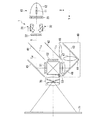
図1は、本発明の実施形態に係る投射型の画像表示装置における光学系部の構造例を示している。本実施形態の光学系部は、画像表示装置に入力された画像信号を投射画像として表示する。
本実施形態の画像表示装置は、R(赤)、G(緑)、B(青)の異なる色ごとに透過型の液晶ライトバルブを備えた3板式の投射型カラー液晶表示装置である。
図1に示す光学系部は、照明装置1、ダイクロイックミラー41,42、反射ミラー43,44,45、液晶ライトバルブ51,52,53、及びクロスダイクロイックプリズム60を備える。
<First Embodiment>
[Image display device: configuration example of optical system]
FIG. 1 shows an example of the structure of an optical system section in a projection type image display apparatus according to an embodiment of the present invention. The optical system unit of the present embodiment displays the image signal input to the image display device as a projection image.
The image display device of the present embodiment is a three-plate projection type color liquid crystal display device provided with a transmissive liquid crystal light valve for each of different colors of R (red), G (green), and B (blue).
The optical system unit shown in FIG. 1 includes an illumination device 1,
照明装置1は、光源10とフライアイレンズ21,22と遮光板31,32とを備える。光源10は、高圧水銀ランプ等のランプ11と、ランプ11の光を反射するリフレクタ12とを備える。
The illumination device 1 includes a
第1のフライアイレンズ21と第2のフライアイレンズ22は、光源光の照度分布を被照明領域である液晶ライトバルブ51,52,53において均一化させるために設けられる。第1のフライアイレンズ21は光源10からの光が入射されるように設けられ、第2のフライアイレンズ22は、第1のフライアイレンズ21を通過した光が入射されるように配置される。
第1のフライアイレンズ21は光源10から射出された光を複数の光束Rに分割し、第2のフライアイレンズ22はライトバルブ位置においてそれらを重畳する重畳レンズとしての機能を有する。場合によっては2次光源像を重畳するためのコンデンサーレンズを第2のフライアイレンズ22の位置、もしくはその後段に配しても良い。以下では重畳レンズとして第2のフライアイレンズ22が用いられた場合について説明を行う。
本実施形態の場合、光源10から射出された光の光量を調節する調光素子として、遮光板31,32が第1のフライアイレンズ21と第2のフライアイレンズ22との間に回動可能に設置されている。
The first fly-
The first fly-
In the case of the present embodiment, the
次に、図1における照明装置1の後段の構成について説明する。
青色光・緑色光反射のダイクロイックミラー41は、光源10からの光束のうちの赤色光LRを透過させるとともに、青色光LBと緑色光LGとを反射させる。ダイクロイックミラー41を透過した赤色光LRは反射ミラー45で反射されて赤色光用の液晶ライトバルブ51に入射される。一方、ダイクロイックミラー41で反射した色光のうち、緑色光LGは緑色光反射用のダイクロイックミラー42によって反射され、緑色光用の液晶ライトバルブ52に入射される。一方、青色光LBはダイクロイックミラー42も透過し、リレーレンズ46、反射ミラー43、リレーレンズ47、反射ミラー44、リレーレンズ48からなるリレー系49を経て青色光用の液晶ライトバルブ53に入射される。
Next, the structure of the latter stage of the illuminating device 1 in FIG. 1 is demonstrated.
The blue / green light reflecting
液晶ライトバルブ51,52,53の各々によって変調された3つの色光は、クロスダイクロイックプリズム60に入射される。クロスダイクロイックプリズム60は4つの直角プリズムが貼り合わされ、その内面に赤色光を反射する誘電体多層膜と青色光を反射する誘電体多層膜とが十字状に形成されている。これらの誘電体多層膜によって3つの色光が合成されてカラー画像を表す光が形成される。合成された光は投射光学系である投射レンズ70によりスクリーン71上に投射され、拡大された画像が表示される。
The three color lights modulated by the liquid
次に、図2及び図3を参照して、本実施形態の照明装置1における調光機能について説明する。ここでの照明装置1としては、2枚のフライアイレンズの間に遮光板を装入した照明装置の例を示す。図2及び図3は、それぞれ、本実施形態の照明装置の概略構成を示す側面図及び平面図である。なお、図2及び図3において、図1と同一部分には同一符号を付して説明を省略する。 Next, with reference to FIG.2 and FIG.3, the light control function in the illuminating device 1 of this embodiment is demonstrated. Here, an example of an illuminating device 1 in which a light shielding plate is inserted between two fly-eye lenses is shown as the illuminating device 1. 2 and 3 are a side view and a plan view, respectively, showing a schematic configuration of the illumination device of the present embodiment. 2 and 3, the same parts as those in FIG.
第1のフライアイレンズ21と第2のフライアイレンズ22との間には調光素子30が設置されている。調光素子30は、画像表示のために光源10から射出された光を遮断する遮光板31,32により形成される開口部の開口率が変更されることにより光量を変更する。このために、調光素子30は、光源10から第1のフライアイレンズ21を通過した光束Rの一部又は全部を遮光可能な一対の遮光板31,32と、これらの遮光板31,32をそれぞれ回動可能な回動装置33とを備える。
A dimming
遮光板31,32は、矩形の平面部31a,32aと、この平面部31a,32aの両端部に取り付けられた腕部31b,32bとを備える。腕部31b,32bには、平面部31a,32aの主面に平行な方向に延在する回動軸31c,32cが設けられ、平面部31a,32aはそれぞれ回動軸31c,32cを中心として回動可能に構成されている。これらの遮光板31,32はその形状及び回動半径等を等しく構成されている。
The
また、回動軸31c,32cは第1のフライアイレンズ21側に配置されており、回動に伴って、平面部31a,32aの第2のフライアイレンズ22側の端部が第2のフライアイレンズ22の表面に沿って移動されるようになっている。なお、腕部31b,32bは、図3に示すように、光を遮蔽しないように、第1のフライアイレンズ21からの射出光の光路外に配置されている。
Further, the
回動軸31c,32cの回動装置33は、図3に示すように、各回動軸31c,32cに取り付けられた歯車33b,33cと、この一方の歯車33cを回動させる1台のステッピングモータ(駆動源)33aとを備えている。歯車33b,33cは、互いに噛合して回動されることで回動軸31c,32cを互いに反対方向に等しい回動量で回動するようになっている。
As shown in FIG. 3, the
各遮光板31,32は、調光を行わない初期状態において、図2に示すように、その平面部31a,32aが光軸Yと平行に配置されている。また、この初期状態において各平面部31a,32aは第1のフライアイレンズ21から射出される光の光路外に配置されており、遮光量が略ゼロとなるように構成されている。一方、調光を行う場合(調光状態)には、各平面部31a,32aは、これと離れた位置に設けられた回動軸31c,32cを中心として回動量θ=0°〜90°の範囲内で回動される。そして、この回動量θを回動装置33によって変更することで遮光板31,32の位置状態が変化し、光源10からの射出光の光量が調節されるようになっている。
As shown in FIG. 2, the
[画像表示装置:調光制御系の構成例]
次に、図4を参照して、本実施形態の画像表示装置における調光制御系(調光制御装置)の構成例について説明する。
この図に示す画像表示装置は、画像特徴量算出部101、伸張率設定部102、伸張率テーブル記憶部103、伸張処理部104、開口率設定部105、開口率テーブル記憶部106、画像判定部107及び調光制御部108を備える。
また、この図においては、輝度伸張処理が施された画像信号により光変調を行う液晶ライトバルブ51,52,53と、調光制御部108により駆動される調光素子30が示されている。
[Image display device: configuration example of dimming control system]
Next, a configuration example of a dimming control system (dimming control device) in the image display apparatus according to the present embodiment will be described with reference to FIG.
The image display apparatus shown in this figure includes an image feature
Further, in this figure, liquid
画像特徴量算出部101は、画像信号から画像特徴量を算出する。画像特徴量算出部101は、画像特徴量として、例えば、白ピーク値、APL(Average Picture Level)、輝度ヒストグラム及び彩度ヒストグラムを算出する。画像特徴量算出部101はこれらの画像特徴量を例えば1フレームごとに算出する。
The image feature
画像特徴量としての白ピーク値は、フレームにおける各画素の輝度値のうちの最大値である。画像特徴量算出部101は、1フレームの画像信号を形成する各画素の輝度値のうちで最大の輝度値を白ピーク値として求める。
The white peak value as the image feature amount is the maximum value among the luminance values of each pixel in the frame. The image feature
また、画像特徴量としてのAPLは、フレームにおける輝度の平均値である。
画像特徴量算出部101は、1フレームの画像信号を形成する画素が有する輝度値の平均値を算出し、この平均値をAPLとする。
Further, APL as an image feature amount is an average value of luminance in a frame.
The image feature
また、画像特徴量としての輝度ヒストグラムは、フレームにおける輝度値の度数分布を示す。輝度ヒストグラムにおける度数は、例えば画素数で表される。例えば、輝度が10ビットにより表されるとすると、輝度値は「0〜1023」の範囲である。この場合の輝度ヒストグラムは、「0〜1023」の輝度値の階級ごとに画素がそれぞれいくつあるのかを示す。 A luminance histogram as an image feature amount indicates a frequency distribution of luminance values in a frame. The frequency in the luminance histogram is represented by the number of pixels, for example. For example, if the luminance is represented by 10 bits, the luminance value is in the range of “0 to 1023”. The luminance histogram in this case indicates how many pixels are present for each luminance value class of “0 to 1023”.
画像特徴量算出部101は、1フレームの画像信号を形成する画素を輝度値ごとに振り分け、振り分けられた輝度値ごとの画素の数を輝度ヒストグラムにおける輝度値の階級ごとのビンの値(度数)として設定する。これにより、1フレームに対応する輝度ヒストグラムが求められる。
The image feature
また、画像特徴量としての彩度ヒストグラムは、フレームにおける画素ごとの彩度についての度数分布を示す。彩度ヒストグラムにおける度数も例えば画素数で表される。この場合の彩度ヒストグラムは、彩度の値の階級ごとに画素がそれぞれいくつであるのかを示す。なお、画素ごとの彩度Sは、例えば、R,G,Bの色信号系のもとでは、以下の式により求めることができる。なお、以下の式において、Max(R,G,B)は、R,G,Bの画素値のうちの最大値を示し、Min(R,G,B)は、R,G,Bの画素値のうちの最小値を示す。
S = {Max(R,G,B) - Min(R,G,B)} / Max(R,G,B)・・・(式1)
上記の(式1)は、彩度を「0」〜「1」の範囲となるように正規化する場合の式であるが、正規化を行わない場合、彩度Sは、以下の式により求めることもできる。
S = Max(R,G,B) - Min(R,G,B)・・・(式2)
Further, the saturation histogram as the image feature amount indicates a frequency distribution regarding the saturation for each pixel in the frame. The frequency in the saturation histogram is also expressed by the number of pixels, for example. The saturation histogram in this case indicates how many pixels are in each saturation value class. Note that the saturation S for each pixel can be obtained by the following expression under, for example, an R, G, B color signal system. In the following expression, Max (R, G, B) represents the maximum value among the R, G, B pixel values, and Min (R, G, B) represents the R, G, B pixels. Indicates the minimum value.
S = {Max (R, G, B)-Min (R, G, B)} / Max (R, G, B) (Formula 1)
The above (Expression 1) is an expression for normalizing the saturation to be in the range of “0” to “1”, but when normalization is not performed, the saturation S is expressed by the following expression: You can ask for it.
S = Max (R, G, B)-Min (R, G, B) (Formula 2)
画像特徴量算出部101は、1フレームの画像信号を形成する画素ごとの彩度の値を求める。そのうえで、画素を彩度の値ごとに振り分け、振り分けられた彩度の値ごとの画素(データ)の数を彩度ヒストグラムにおける彩度の値の階級ごとのビンに格納する。これにより、1フレームに対応する彩度ヒストグラムが求められる。
The image feature
伸張率設定部102は、画像特徴量算出部101により算出された画像特徴量に基づいて、伸張処理部104が利用する伸張率Gtを設定する。また、伸張率設定部102は、伸張率Gtを設定するにあたり、伸張率テーブル記憶部103に記憶される伸張率テーブルを参照する。
Expansion
図5は、伸張率テーブルの構造例を示している。なお、この図に示す伸張率テーブルは、画像特徴量である白ピーク値とAPLについてそれぞれ10ビットにより表現した場合の例である。
図5に示す伸張率テーブルは、白ピーク値とAPLの値の組み合わせごとに対応する伸張率の値を格納する二次元テーブルとしての構造を有する。この図の例では、白ピーク値として、0,n1,n2,n3,n4,n5,n6,n7,1023の値が設定されている。ここで、n1,n2,n3,n4,n5,n6,n7は、予め定められた定数である。同様に、APLとしては、0,m1,m2,m3,m4,m5,m6,m7,1023の値が設定されている。m1,m2,m3,m4,m5,m6,m7も予め定められた定数である。なお、n1とm1、n2とm2、n3とm3、n4とm4、n5とm5、n6とm6、n7とm7は、互いに同じ値である必要はない
FIG. 5 shows an example of the structure of the expansion rate table. Note that the expansion rate table shown in this figure is an example when the white peak value and APL, which are image feature amounts, are each expressed by 10 bits.
The expansion rate table shown in FIG. 5 has a structure as a two-dimensional table that stores expansion rate values corresponding to combinations of white peak values and APL values. In the example of this figure, values of 0, n1, n2, n3, n4, n5, n6, n7, 1023 are set as white peak values. Here, n1, n2, n3, n4, n5, n6, and n7 are predetermined constants. Similarly, values of 0, m1, m2, m3, m4, m5, m6, m7, and 1023 are set as APL. m1, m2, m3, m4, m5, m6 and m7 are also predetermined constants. Note that n1 and m1, n2 and m2, n3 and m3, n4 and m4, n5 and m5, n6 and m6, and n7 and m7 do not have to be the same value.
伸張率設定部102は、画像特徴量として白ピーク値とAPLを入力する。伸張率設定部102は、入力した白ピーク値とAPLの組み合わせに対応して格納されている伸張率の値を伸張率テーブルから取得する。
なお、入力した白ピーク値の値が0,n1,n2,n3,n4,n5,n6,n7,1023のいずれの定数にも該当しない場合がある。また、入力したAPLの値が0,m1,m2,m3,m4,m5,m6,m7,1023のいずれの定数にも該当しない場合がある。この場合、伸張率設定部102は、例えば入力した白ピーク値またはAPLの近傍の定数の組み合わせに対応して伸張率テーブルに格納されている値を利用して補間処理を行うことによって伸張率Gtを取得すればよい。
伸張率設定部102は、上記のように伸張率テーブルから取得した値を伸張率Gtとして設定する。
The expansion
The input white peak value may not correspond to any constant of 0, n1, n2, n3, n4, n5, n6, n7, and 1023. Further, the input APL value may not correspond to any constant of 0, m1, m2, m3, m4, m5, m6, m7, and 1023. In this case, the expansion
The expansion
伸張処理部104は、伸張率設定部102により設定された伸張率Gtにしたがって画像信号の輝度の範囲を拡大する輝度伸張処理を実行する。
本実施形態における画像信号は、例えば、R,G,Bの各色に対応する色信号を有する形式である。この場合、伸張処理部104は、R,G,Bの色信号ごとに、伸張率Gtにしたがって輝度範囲を拡大させる。具体的に、伸張処理部104が入力するR,G,Bの各色に対応する色信号をそれぞれrin、gin、binとし、伸張処理部104が出力するR,G,Bの各色に対応する色信号をそれぞれr,g,bとする。そのうえで伸張処理部104は、輝度伸張処理として、例えば以下の(式3)、(式4)、(式5)により色信号r,g,bを求める。
r=rin・Gt・・・(式3)
g=gin・Gt・・・(式4)
b=bin・Gt・・・(式5)
伸張処理部104は、上記のように求めた色信号r,g,bを、それぞれ、液晶ライトバルブ51,52,53に対して出力する。
The
The image signal in the present embodiment has a format having color signals corresponding to R, G, and B colors, for example. In this case, the
r = r in · G t (Formula 3)
g = g in · G t (Formula 4)
b = b in · G t (Formula 5)
The
液晶ライトバルブ51は、入力された色信号rに応じて赤色光LRを変調する。液晶ライトバルブ52は、入力された色信号gに応じて緑色光LGを変調する。液晶ライトバルブ53は、入力された色信号bに応じて青色光LBを変調する。これにより、スクリーン71には、輝度伸張処理による調光制御が行われた画像が表示される。
The liquid crystal
開口率設定部105は、調光素子30の開口部の開口率を画像信号に基づいて設定する。また、開口率設定部105は、開口率を設定するにあたり、画像信号に基づく画像が調光補正対象であると判定された場合には、画像信号に基づく画像が調光補正対象ではないと判定された場合に応じて設定する基礎の開口率(基礎開口率A)を補正した開口率(補正開口率Ac)を設定する。
第1の実施形態において、開口率設定部105は、画像特徴量算出部101により算出された画像信号の画像特徴量に基づいて開口率(基礎開口率A、補正開口率Ac)を設定する。なお、調光素子30の開口部は、調光素子30における遮光板31,32により形成される。開口率は、この開口部についての開口の度合いを示す。開口率が小さくなるほど遮光板31,32により形成される開口部は狭くなり、光源10から射出された光に対する遮光量も増加し、表示される画像が暗くなる。
The aperture
In the first embodiment, the aperture
開口率設定部105は、例えば図示するように、基礎開口率設定部105Aと開口率補正部105Bとを備える。
基礎開口率設定部105Aは、基礎開口率Aを設定する。基礎開口率Aは、補正が行われる前の基礎的な開口率であり、画像信号に基づく画像が調光補正対象ではないと画像判定部107により判定された場合の調光制御に利用されるべき開口率である。
第1の実施形態において、基礎開口率設定部105Aは、基礎開口率Aを設定するにあたり、開口率テーブル記憶部106に記憶される開口率テーブルを参照する。開口率テーブルの構造としては、例えば図5と同様でよい。
基礎開口率設定部105Aは、画像特徴量として白ピーク値とAPLを入力する。基礎開口率設定部105Aは、入力した白ピーク値とAPLの組み合わせに対応する開口率の値を開口率テーブルから取得する。なお、入力した白ピーク値またはAPLの値が開口率テーブルにおいて設定された定数に該当しない場合には、伸張率の場合と同様に補間処理を行って開口率を取得すればよい。基礎開口率設定部105Aは、このように開口率テーブルから取得した値を基礎開口率Aとして設定する。
なお、開口率補正部105Bについては後述する。
The aperture
The basic aperture
In the first embodiment, the basic aperture
The basic aperture
The aperture
画像判定部107は、画像信号の画像特徴量に基づいて、画像信号に基づく画像が調光補正対象であるか否かについて判定する。
ここで、調光補正対象の画像とは、色むらなどのように光源10からの光量の減少に起因する画質劣化が生じている場合に、その画質劣化がカラーによる自然画像よりも目立ちやすい内容の画像をいう。本実施形態において調光補正対象に該当する画像としては、例えばラスター画像とモノクローム画像である。また、ここでの調光補正とは、このようなラスター画像やモノクローム画像などが表示されるのに対応して、ラスター画像やモノクローム画像が表示されてないときに設定される光量とは異なる光量となるように調光制御を行うことをいう。
The
Here, the image subject to dimming correction is content in which the image quality deterioration is more conspicuous than the natural image due to color when there is image quality deterioration caused by a decrease in the amount of light from the
ラスター画像は、単色により一様に分布する画像である。このような画像では画面全体において色の変化が無いために、色ずれが生じている場合にはその色ずれが目立つ。また、輝度についてみた場合、ラスター画像は、画面全体において輝度が同じになる。この点で、ラスター画像は、画面において同じ輝度が一様に分布する画像である。
また、モノクローム画像は色彩の無い輝度のみにより表現される画像である。このような画像も、色ずれが生じた場合には本来色彩の無い画像に色が現れることになるために、その色ずれが目立つ。
画像判定部107は、画像信号に基づく画像がラスター画像とモノクローム画像のいずれか一方であると判定した場合に調光補正対象であると判定する。
A raster image is an image that is uniformly distributed by a single color. In such an image, since there is no color change in the entire screen, when there is a color shift, the color shift is conspicuous. In terms of luminance, the raster image has the same luminance throughout the screen. In this respect, the raster image is an image in which the same luminance is uniformly distributed on the screen.
In addition, a monochrome image is an image that is expressed only by luminance having no color. In such an image as well, when a color shift occurs, the color appears in an originally non-colored image, so the color shift is conspicuous.
If the
第1の実施形態において、画像判定部107は、例えば以下のようにラスター画像について判定する。
画像判定部107は、画像特徴量として白ピーク値とAPLを入力する。そして、画像判定部107は、入力した白ピーク値とAPLとを比較し、白ピーク値とAPLとが同じ値であるか否かについて判定する。
白ピーク値とAPLが同じ値であるということは、全体において輝度が一様に分布した画像、つまり、ラスター画像であることになる。そこで、画像判定部107は、白ピーク値とAPLとが同じ値である場合にラスター画像であると判定する。
In the first embodiment, the
The
That the white peak value and APL are the same value means that the image has a uniformly distributed luminance, that is, a raster image. Therefore, the
ここで、ラスター画像であっても、ノイズなどの影響で白ピーク値とAPLとについてある程度の差分が生じる可能性がある。また、画面において輝度のむらがある程度あっても視覚的にはラスター画像として見えるような画像であれば色むらは目立つことから、画像判定部107によりラスター画像として判定されるようにしたほうが好ましい。
このような観点から、画像判定部107は、白ピーク値とAPLとが同じ値とみなせる一定のマージン値を設定し、この白ピーク値とAPLの値の差分値がマージン値以内であればラスター画像であると判定する。つまり、画像判定部107は、白ピーク値とAPLとの差分が一定値以内 (マージン以内)である場合に、白ピーク値とAPLとが同じ値であるとみなして、ラスター画像であると判定する。
Here, even in the case of a raster image, there is a possibility that a certain amount of difference occurs between the white peak value and the APL due to the influence of noise or the like. In addition, even if there is a certain amount of luminance unevenness on the screen, color unevenness is conspicuous if the image is visually visible as a raster image. Therefore, it is preferable that the
From this point of view, the
また、画像判定部107は、例えば以下のようにモノクローム画像について判定する。
画像判定部107は、画像特徴量としての彩度ヒストグラムを入力し、彩度ヒストグラムを解析する。画像判定部107は、彩度が「0(ゼロ)」の階級にすべてのデータが存在しているとの解析結果が得られた場合にモノクローム画像であると判定する。
モノクローム画像は、輝度成分のみによる画像であるために、フレームにおけるどの画素についても彩度は「0」である。したがって、モノクローム画像の彩度ヒストグラムは、彩度の値が「0」の階級にすべてのデータが存在しているというものになる。
The
The
Since the monochrome image is an image having only the luminance component, the saturation is “0” for any pixel in the frame. Therefore, the saturation histogram of the monochrome image is such that all data exists in the class having the saturation value of “0”.
ここで、モノクローム画像の場合にも、ノイズなどの影響で、彩度ヒストグラムにおいて「0」以外の値の階級において1以上のデータが存在してしまう場合がある。このようなことを考慮して、画像判定部107は、以下のようにモノクローム画像について判定する。つまり、画像判定部107は、彩度ヒストグラムにおいて彩度がゼロの階級を含む一定範囲の階級に全データのうちの一定比率以上のデータが存在する場合に、彩度がゼロの階級にすべてのデータが存在しているとみなして、モノクローム画像であると判定する。
Here, even in the case of a monochrome image, one or more data may exist in a class of values other than “0” in the saturation histogram due to the influence of noise or the like. In consideration of this, the
開口率設定部105において、開口率補正部105Bは、画像判定部107による判定結果に応じて基礎開口率設定部105Aにより設定された基礎開口率Aを補正し、補正した開口率を補正開口率Acとして設定する。
例えば、開口率補正部105Bは、調光補正対象の画像ではないと画像判定部107により判定された場合には、基礎開口率設定部105Aにより設定された基礎開口率Aをそのまま補正開口率Acとして設定する。つまり、この場合の開口率補正部105Bは、基礎開口率Aについての補正は行わない。
In the aperture
For example, when the
これに対して、開口率補正部105Bは、調光補正対象の画像であると画像判定部107により判定された場合には基礎開口率Aを補正し、この補正により求められた値を補正開口率Acとして設定する。
開口率補正部105Bは、基礎開口率Aを補正するにあたり、例えば、予め定められた補正係数kにより基礎開口率Aを乗算し、乗算により求められた値を補正開口率Acとして設定すればよい。なお、この場合の補正係数kは、1より大きい値である。これにより、補正開口率Acは、補正前の基礎開口率Aよりも大きくなる。このように、補正開口率Acが基礎開口率Aよりも大きい値に補正されることで、補正開口率Acに基づく調光制御では、遮光板31,32により形成される開口部が拡げられることになって光量が増加し、画像の色むらが軽減される。
In contrast, the aperture
In correcting the basic aperture ratio A, for example, the aperture
なお、開口率補正部105Bが基礎開口率Aを補正して補正開口率Acを設定する手法としては上記の例に限定されるものではない。
例えば、開口率補正部105Bは、予め定めた補正加算値k1を基礎開口率Aに加算し、加算により求められた値を補正開口率Acとして設定してもよい。
また、開口率補正部105Bは、例えば、開口率についての下限許容値を補正開口率Acとして設定してもよい。この下限許容値は、例えばラスター画像やモノクローム画像などの画像において色むらが視覚的に許容できる開口率の限度値に一定のマージンとしての値を加算することにより設定できる。
Note that the aperture
For example, the aperture
In addition, the aperture
調光制御部108は、開口率設定部105により設定された開口率(補正開口率Ac)に基づいて調光素子30を制御することにより、画像表示のために光源10から射出された光量を変更する。
具体的に、調光制御部108は、補正開口率Acの状態が得られる回動量θを算出し、調光素子30における遮光板31,32の平面部31a,32aが回動量θに応じた位置状態となるように回動装置33を駆動する。
The dimming
Specifically, the dimming
ここで、画像判定部107により調光補正対象の画像ではないと判定された場合には、基礎開口率設定部105Aにより設定された基礎開口率Aによる光量調節が行われる。このときスクリーンに表示されている画像は、例えば、カラーによる自然画像であるために、色むらが生じているとしても視覚的に気付きにくく、特に画像を鑑賞するにあたっての障害にはならない。
Here, when the
これに対して、画像判定部107により調光補正対象の画像であると判定された場合には、補正開口率Acによる光量調節が行われる。つまり、例えばラスター画像やモノクローム画像などが表示されている状態では基礎開口率Aよりも大きな開口率による光量調節が行われる。これにより、フライアレイレンズにおいて光束が透過するレンズのセルの数が増加するために色むらが抑制される。この結果、ユーザーは、例えばラスター画像やモノクローム画像などが表示されているときであっても、自然画像のときと同様に、色むらを気にすることなく鑑賞することができる。
On the other hand, when the
[処理手順例]
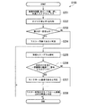
図6のフローチャートは、第1の実施形態における画像表示装置が調光素子30を利用して調光制御を実行するための処理手順例を示している。なお、この図に示す処理は、例えば画像信号のフレームごとのタイミングに応じて実行される。
[Example of processing procedure]
The flowchart in FIG. 6 illustrates an example of a processing procedure for the image display apparatus according to the first embodiment to perform dimming control using the dimming
画像特徴量算出部101は、フレームごとに画像信号の画像特徴量を算出している。基礎開口率設定部105Aは、現フレームに対応して画像特徴量算出部101が算出した画像特徴量のうち、白ピーク値とAPLを入力する(ステップS101)。
次に、基礎開口率設定部105Aは、開口率テーブル記憶部106に記憶されている開口率テーブルを参照して、入力した白ピーク値とAPLの組み合わせに応じた開口率の値を取得し、この取得した値を基礎開口率Aとして設定する(ステップS102)。
The image feature
Next, the basic aperture
また、画像判定部107は、現フレームに対応して算出された画像特徴量を利用して現フレームの画像信号に基づく画像の内容について判定する(ステップS103)。具体的に、画像判定部107は、ステップS103において、現フレームの画像信号に基づく画像がラスター画像またはモノクローム画像であるか否かについて判定する。
次に、画像判定部107は、ステップS103による画像についての判定結果に応じて、現フレームの画像信号に基づく画像が調光補正対象であるか否かについて判定する(ステップS104)
In addition, the
Next, the
画像判定部107は、ステップS103によりラスター画像またはモノクローム画像であるとの判定結果が得られた場合、現フレームの画像信号に基づく画像が調光補正対象であると判定する(ステップS104−YES)。
この場合、開口率補正部105Bは、ステップS102により設定された基礎開口率Aについて補正(変更)を行い、補正により求められた値を補正開口率Acとして設定する(ステップS105)。
If the determination result that the image is a raster image or a monochrome image is obtained in step S103, the
In this case, the aperture
一方、ステップS103によりラスター画像及びモノクローム画像以外の画像であるとの判定結果が得られた場合、現フレームの画像信号に基づく画像は、例えばカラーによる自然画像などであることになる。この場合、画像判定部107は、現フレームの画像信号に基づく画像は調光補正対象ではないと判定する(ステップS104−NO)。
この場合、開口率補正部105Bは、補正開口率Acに対して、ステップS102により設定された基礎開口率Aを代入するようにして補正開口率Acを設定する(ステップS106)。つまり、この場合の開口率補正部105Bは基礎開口率Aについて補正を行わない。
On the other hand, when it is determined in step S103 that the image is other than the raster image and the monochrome image, the image based on the image signal of the current frame is, for example, a color natural image. In this case, the
In this case, the aperture
調光制御部108は、ステップS105またはS106により設定された補正開口率Acに応じた遮光板31,32の位置状態となるように調光素子30を制御する(ステップS107)。
The dimming
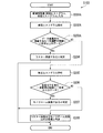
図7のフローチャートは、画像判定部107が図6のステップS103として実行する画像判定のための処理手順例を示している。
図7におけるステップS201〜S204は、ラスター画像についての判定に関連する処理である。画像判定部107は、画像特徴量算出部101が算出した現フレームの画像信号の画像特徴量として白ピーク値、APL及び彩度ヒストグラムを入力する(ステップS201)。
次に、画像判定部107は、入力した白ピーク値とAPLとを比較し(ステップS202)、両者の差分が一定値以内であるか否かについて判定する(ステップS203)。
白ピーク値とAPLとの差分が一定値以内である場合(ステップS203−YES)、画像判定部107は、現フレームの画像信号に基づく画像はラスター画像であると判定する(ステップS204)。
The flowchart in FIG. 7 illustrates an example of a processing procedure for image determination performed by the
Steps S201 to S204 in FIG. 7 are processes related to the determination on the raster image. The
Next, the
When the difference between the white peak value and the APL is within a certain value (step S203—YES), the
また、白ピーク値とAPLとの差分が一定値を越える場合(ステップS203−NO)、画像判定部107は、モノクローム画像についての判定に関連する処理(ステップS205〜S208)に移行する。
画像判定部107は、画像特徴量として入力した彩度ヒストグラムを解析する(ステップS205)。次に、画像判定部107は、解析結果から、彩度ヒストグラムにおいて彩度がゼロの階級を含む一定範囲の階級に全データのうちの一定比率以上のデータが存在するか否かについて判定する(ステップS206)。
When the difference between the white peak value and the APL exceeds a certain value (step S203—NO), the
The
彩度ヒストグラムにおいて彩度がゼロの階級を含む一定範囲の階級に全データのうちの一定比率以上のデータが存在する場合には(ステップS206−YES)、フレームにおける全画素の彩度が「0」の画像であるとみてよい。そこで、この場合の画像判定部107は、現フレームの画像信号に基づく画像がモノクローム画像であると判定する(ステップS207)。
When data of a certain ratio or more of all data exists in a certain range of classes including a class with zero saturation in the saturation histogram (step S206—YES), the saturation of all pixels in the frame is “0”. It may be considered that the image is "." Therefore, the
一方、彩度ヒストグラムにおいて彩度がゼロの階級を含む一定範囲の階級に全データのうちの一定比率以上のデータが存在していない場合(ステップS206−NO)、一定範囲外の階級においてもデータが離散して存在しており、したがってモノクローム画像ではないということになる。この場合、画像判定部107は、現フレームの画像信号に基づく画像は、ラスター画像及びモノクローム画像以外の画像(例えばカラーによる自然画像など)であると判定する(ステップS208)。
On the other hand, in the saturation histogram, when there is no data of a certain ratio or more of all data in a certain range of classes including a class with zero saturation (step S206-NO), data is also obtained in a class outside the certain range. Exist discretely, and thus are not monochrome images. In this case, the
画像判定部107は、図7のステップS204によりラスター画像であると判定した場合、もしくはステップS208によりモノクローム画像であると判定した場合に、図6のステップS104において調光補正対象であると判定する(ステップS104−YES)。
一方、画像判定部107は、図7のステップS208によりラスター画像及びモノクローム画像以外の画像であると判定した場合に、図6のステップS104において調光補正対象ではないと判定する(ステップS104−NO)。
If the
On the other hand, when it is determined in step S208 in FIG. 7 that the
なお、図4の構成の開口率設定部105においては、まず、基礎開口率設定部105Aにより基礎開口率Aを設定したうえで、画像判定部107の判定結果に応じて基礎開口率Aを補正するという段階的な処理を行うようにされている。
しかし、例えば、開口率設定部105は、次のように調光制御部108に与える開口率を設定してもよい。
つまり、開口率テーブルについて、白ピーク値やAPLなどの画像特徴量によるパラメータと、画像判定部107による調光補正対象の画像であるか否かの判定結果に応じたパラメータとの組み合わせに開口率の値を対応付けた3次元以上のテーブルとして構成する。
そのうえで、開口率設定部105は、画像特徴量算出部101により算出された画像特徴量と、画像判定部107による判定結果との組み合わせに応じて格納されている開口率の値を開口率テーブルから取得する。そして、開口率設定部105は、このように開口率テーブルから取得した値を、調光制御部108に与える開口率(図4の補正開口率Acに相当する)として設定するものである。このように開口率を設定する場合、開口率設定部105は、基礎開口率設定部105Aと開口率補正部105Bの各機能部を特に個別に備える構成でなくともよい。
In the aperture
However, for example, the aperture
That is, in the aperture ratio table, the aperture ratio is a combination of a parameter based on an image feature amount such as a white peak value or APL and a parameter according to a determination result of whether or not the image is a dimming correction target image by the
In addition, the aperture
<第2の実施形態>
[概要]
続いて、第2の実施形態について説明する。
なお、第2の実施形態に係る画像表示装置における調光制御系の構成は、図4と同様でよい。
<Second Embodiment>
[Overview]
Next, the second embodiment will be described.
The configuration of the dimming control system in the image display apparatus according to the second embodiment may be the same as that shown in FIG.
第2の実施形態においては、ラスター画像であるか否かを判定するための画像判定部107の処理が第1の実施形態と異なる。第2の実施形態において、画像判定部107は、ラスター画像であるか否かを判定するにあたり、画像特徴量における輝度ヒストグラムを利用する。
In the second embodiment, the processing of the
つまり、第2の実施形態における画像判定部107は、画像特徴量算出部101が算出した画像特徴量として輝度ヒストグラムを入力する。画像判定部107は、入力した輝度ヒストグラムを解析し、その解析結果として、輝度ヒストグラムにおいて特定の1つの階級にすべてのデータが存在しているとされる場合に、ラスター画像であると判定する。
輝度ヒストグラムにおいて特定の1つの階級にすべてのデータが存在しているということは、フレームにおけるすべての画素がその特定の階級に対応する同じ輝度値を有しているということである。つまり、この輝度ヒストグラムは、画面において輝度が一様のラスター画像としての特徴を反映している。
ただし、この場合にも、画像信号のノイズや、画面において輝度にある程度のむらが有る画像であってもラスター画像として判定されるようにすることを考慮して、判定基準に一定のマージンを与えることが好ましい。つまり、画像判定部107は、輝度ヒストグラムにおいてデータ数が最大の階級を含む一定範囲の階級に全データのうちの一定比率以上のデータが存在する場合に、特定の1つの階級にすべてのデータが存在しているものとみなして、ラスター画像であると判定する。
That is, the
The presence of all data in a particular class in the luminance histogram means that all pixels in the frame have the same luminance value corresponding to that particular class. That is, this luminance histogram reflects the characteristics of a raster image with uniform luminance on the screen.
However, in this case as well, a certain margin should be given to the judgment criterion in consideration of making it judged as a raster image even if it is an image signal noise or an image having a certain amount of luminance unevenness on the screen. Is preferred. That is, the
[処理手順例]
第2の実施形態において画像表示装置が調光素子30を利用した調光制御のために実行する処理手順としては、例えば図6と同様でよい。ただし、図6のステップS103としての画像判定においてラスター画像を判定するための処理手順が第1の実施形態と異なる。
[Example of processing procedure]
In the second embodiment, the processing procedure executed for the dimming control using the dimming
図8は、第2の実施形態において、図6のステップS103の画像判定として実行される処理手順例を示している。なお、この図において、図7と同様の処理となるステップについては同一符号を付して説明を省略する。
画像判定部107は、画像特徴量算出部101が算出した現フレームの画像信号の画像特徴量として輝度ヒストグラムと彩度ヒストグラムを入力する(ステップS201A)。
次に、画像判定部107は、輝度ヒストグラムを解析し(ステップS202A)、その解析結果から、輝度ヒストグラムにおいてデータ数が最大の階級を含む一定範囲の階級に全データのうちの一定比率以上のデータが存在するか否かについて判定する(ステップS203A)。
データ数が最大の階級を含む一定範囲の階級に全データのうちの一定比率以上のデータが存在すると判定した場合(ステップS203A−YES)、画像判定部107は、現フレームの画像信号に基づく画像はラスター画像であると判定する(ステップS204)。
一方、データ数が最大の階級を含む一定範囲の階級に全データのうちの一定比率以上のデータが存在していないと判定した場合(ステップS203A−NO)、現フレームの画像は、一定範囲外の階級にもデータが離散して存在しており、ラスター画像ではない。そこで、この場合の画像判定部107は、ステップS205以降の処理に移行する。なお、ステップS205〜S208の処理は、図7と同様である。
FIG. 8 shows an example of a processing procedure executed as the image determination in step S103 of FIG. 6 in the second embodiment. In this figure, steps that are the same as those in FIG. 7 are denoted by the same reference numerals and description thereof is omitted.
The
Next, the
When it is determined that there is data of a certain ratio or more of all data in a certain range of classes including the class having the maximum number of data (step S203A-YES), the
On the other hand, when it is determined that there is no data exceeding a certain ratio of all data in a certain range of classes including the class having the maximum number of data (step S203A-NO), the image of the current frame is out of the certain range. Data is also discretely present in this class, and is not a raster image. Therefore, the
<第3の実施形態>
[画像表示装置:調光制御系の構成例]
次に、第3の実施形態について説明する。
図9は、第3の実施形態に係る画像表示装置における調光制御系の構成例を示している。なお、この図において図4と同一部分には同一符号を付して説明を省略する。
図9に示す基礎開口率設定部105Aは、伸張率設定部102により設定された伸張率Gtを入力する。基礎開口率設定部105Aは、伸張率Gtに基づいて基礎開口率Aを設定する。このように基礎開口率設定部105Aが伸張率Gtに基づいて基礎開口率Aを設定するのに伴い、図9においては、図4に示されていた開口率テーブル記憶部106が省略されている。
<Third Embodiment>
[Image display device: configuration example of dimming control system]
Next, a third embodiment will be described.
FIG. 9 shows a configuration example of a dimming control system in the image display apparatus according to the third embodiment. In this figure, the same parts as those in FIG.
The basic aperture
輝度伸張処理によっては、例えば画像の輝度が低くなるのに応じて輝度範囲を拡大することでダイナミックレンジを拡大する。したがって、輝度伸張処理のための伸張率Gtは、輝度の低下に応じて高くなるように設定される。また、調光素子30に対する調光制御によっては、光源10からの射出光を遮蔽して光量を低減させることにより光漏れや迷光を抑制して黒浮きを低減できる。このことからすると、例えば画像の輝度が低くなるのに応じて、光量を低減させていくことで黒浮きが有効に抑制される。この場合、基礎開口率Aは、例えば伸張率Gtを高くするのに応じて小さくしていくように設定するとよい。
Depending on the luminance expansion processing, for example, the dynamic range is expanded by expanding the luminance range as the luminance of the image decreases. Thus, extension ratio G t for luminance expansion processing is set to be higher with a decrease in luminance. Further, depending on the dimming control for the dimming
第3の実施形態における基礎開口率設定部105Aは、例えば、伸張率Gtを利用して以下の式による演算を行うことで、伸張率Gtが高くなるのに応じて小さくなるように基礎開口率Aを設定することができる。なお、γはガンマ値であり、例えば2.2の値をとる。
A=Gt −γ・・・(式6)
なお、伸張率Gtが高くなるのに応じて小さくなるように基礎開口率Aを求めるための手法としては、(式6)による演算に限定されるものではない。
Third basic opening
A = G t −γ (Expression 6)
Note that the technique for obtaining the basic aperture ratio A so as to decrease as the expansion ratio Gt increases is not limited to the calculation according to (Equation 6).
[処理手順例]
図10のフローチャートは、第3の実施形態における画像表示装置が調光素子30を利用して調光制御を実行するための処理手順例を示している。なお、図10において図6と同様の処理となるステップについては同一符号を付して説明を省略する。
[Example of processing procedure]
The flowchart in FIG. 10 illustrates an example of a processing procedure for the image display apparatus according to the third embodiment to perform dimming control using the dimming
第3の実施形態における基礎開口率設定部105Aは、伸張率設定部102により設定された伸張率Gtを入力する(ステップS101A)。
次に、基礎開口率設定部105Aは、入力した伸張率Gtに基づいて基礎開口率Aを設定する(ステップS102A)。例えば、基礎開口率設定部105Aは、(式6)の演算によって算出した値を基礎開口率Aとして設定する。
The basic aperture
Next, the basic aperture
なお、図10におけるステップS103〜S107の各処理は、図6と同様である。
また、第3の実施形態における画像判定部107がラスター画像を判定するにあたっては、第1の実施形態のように白ピーク値とAPLとを比較してもよいし、第2の実施形態のように輝度ヒストグラムを解析した結果に基づいてもよい。
In addition, each process of step S103-S107 in FIG. 10 is the same as that of FIG.
In addition, when the
また、図9の構成の開口率設定部105は、次のように調光制御部108に与える開口率を設定してもよい。
つまり、開口率設定部105は、例えば(式6)に代えて、伸張率Gtと画像判定部107による調光補正対象の画像であるか否かの判定結果に応じた変数とを含む所定の演算式について演算することより開口率(図4の補正開口率Acに相当する)を求める。このように開口率を設定する場合も、開口率設定部105は、基礎開口率設定部105Aと開口率補正部105Bの各機能部を特に個別に備える構成でなくともよい。
Further, the aperture
In other words, the aperture
<変形例>
[第1の変形例]
次に、本実施形態における変形例について説明する。
まず、第1の変形例として、画像判定部107がラスター画像を判定するにあたっては、画像特徴量としての白ピーク値とAPLとを比較する処理と、画像特徴量としての輝度ヒストグラムを解析する処理とを組み合わせてもよい。
一例として、画像判定部107は、白ピーク値とAPLとを比較することによってラスター画像であると判定し、かつ、輝度ヒストグラムを解析した結果によりラスター画像であると判定した場合にのみ、最終的にラスター画像であると判定するようにしてよい。
<Modification>
[First Modification]
Next, a modified example in the present embodiment will be described.
First, as a first modification, when the
As an example, the
[第2の変形例]
また、調光補正対象に該当する画像として、ラスター画像とモノクローム画像の他に、グラデーション画像を含めてもよい。グラデーション画像は、例えば明るさや色が徐々に変化するグラデーションが表現された画像である。このグラデーション画像は、特に単色のグラデーションや少ない色の間でのグラデーションが表現されている場合に、色むらなどの光源からの光量減少に起因する画質劣化が目立ちやすい。
グラデーション画像では、例えば輝度や色相などが画面における一定の方向に沿って滑らかな変化を示す。そこで、例えば画像判定部107は、画像特徴量算出部101が算出した画像特徴量としての画素の位置ごとの輝度や画素の位置ごとの色相の情報などを入力し、これらの輝度や色相などについての画面上での方向に応じた変化を解析する。そして、画像判定部107は、この解析の結果、輝度や色相などが画面の特定方向に沿って緩慢な変化を示していると判断したのであれば、グラデーション画像であると判定すればよい。なお、緩慢な変化を示しているか否かについては、所定の画面方向ごとにおける輝度や色相の変化量あるいは変化率が予め定めた閾値以下であるか否かについて判定すればよい。
あるいは、より簡易に、色相ヒストグラムが色の数が一定以下に少ないことを示し、かつ、輝度ヒストグラムが全体あるいは一部の区間の階級で度数が一様に分布している状態のときに、グラデーション画像であると判定してよい。
色相については、Cr、Cbなどによる色差信号に基づいて求めることができる。あるいは、R,G,B信号であれば、色相は、R,G,B信号の大小関係に基づいて求めることができる。R,G,B信号に基づく場合には、下記の式により色相Hを求めることができる。なお、下記の式は、色相Hが「0」〜「359」の範囲での値を採る場合の例に対応する。
つまり、R,G,Bの画素値のうちの最大値がRである場合には、
H=60*(G-B)/{Max(R,G,B)-Min(R,G,B)}・・・(式7)
により色相Hを求めることができる。
また、R,G,Bの画素値のうちの最大値がGである場合には、
H=60*(B-R)/{Max(R,G,B)-Min(R,G,B)}+120・・・(式8)
により色相Hを求めることができる。
また、R,G,Bの画素値のうちの最大値がBである場合には、
H=60*(R-G)/{Max(R,G,B)-Min(R,G,B)}+240・・・(式9)
により色相Hを求めることができる。
[Second Modification]
In addition to the raster image and the monochrome image, a gradation image may be included as an image corresponding to the light adjustment correction target. The gradation image is, for example, an image expressing gradation in which brightness and color gradually change. In this gradation image, particularly when a gradation of a single color or a gradation between few colors is expressed, image quality deterioration due to a decrease in the amount of light from the light source such as color unevenness is conspicuous.
In the gradation image, for example, brightness, hue, and the like show a smooth change along a certain direction on the screen. Therefore, for example, the
Or, more simply, when the hue histogram shows that the number of colors is less than a certain level, and the luminance histogram is in a state where the frequency is uniformly distributed in the whole or part of the class, the gradation You may determine that it is an image.
The hue can be obtained based on a color difference signal such as Cr or Cb. Alternatively, in the case of the R, G, and B signals, the hue can be obtained based on the magnitude relationship between the R, G, and B signals. When based on the R, G, and B signals, the hue H can be obtained by the following equation. The following expression corresponds to an example in which the hue H takes a value in the range of “0” to “359”.
That is, when the maximum value among the R, G, and B pixel values is R,
H = 60 * (GB) / {Max (R, G, B) -Min (R, G, B)} (Expression 7)
Thus, the hue H can be obtained.
When the maximum value among the R, G, and B pixel values is G,
H = 60 * (BR) / {Max (R, G, B) -Min (R, G, B)} + 120 (Equation 8)
Thus, the hue H can be obtained.
When the maximum value among the R, G, and B pixel values is B,
H = 60 * (RG) / {Max (R, G, B) -Min (R, G, B)} + 240 (Equation 9)
Thus, the hue H can be obtained.
また、遮光板を備える構造の調光素子30としては、例えば図2及び図3に示した以外の構造が採られてもよい。
Moreover, as the
また、図4及び図9における機能部を実現するためのプログラムをコンピュータ読み取り可能な記録媒体に記録して、この記録媒体に記録されたプログラムをコンピュータシステムに読み込ませ、実行することにより調光制御を行ってもよい。なお、ここでいう「コンピュータシステム」とは、OSや周辺機器等のハードウェアを含むものとする。 Further, dimming control is performed by recording a program for realizing the functional units in FIGS. 4 and 9 on a computer-readable recording medium, causing the computer system to read and execute the program recorded on the recording medium. May be performed. Here, the “computer system” includes an OS and hardware such as peripheral devices.
また、「コンピュータシステム」は、WWWシステムを利用している場合であれば、ホームページ提供環境(あるいは表示環境)も含むものとする。
また、「コンピュータ読み取り可能な記録媒体」とは、フレキシブルディスク、光磁気ディスク、ROM、CD−ROM等の可搬媒体、コンピュータシステムに内蔵されるハードディスク等の記憶装置のことをいう。さらに「コンピュータ読み取り可能な記録媒体」とは、インターネット等のネットワークや電話回線等の通信回線を介してプログラムが送信された場合のサーバやクライアントとなるコンピュータシステム内部の揮発性メモリ(RAM)のように、一定時間プログラムを保持しているものも含むものとする。また上記プログラムは、前述した機能の一部を実現するためのものであっても良く、さらに前述した機能をコンピュータシステムにすでに記録されているプログラムとの組み合わせで実現できるものであってもよい。
Further, the “computer system” includes a homepage providing environment (or display environment) if a WWW system is used.
The “computer-readable recording medium” refers to a storage device such as a flexible medium, a magneto-optical disk, a portable medium such as a ROM and a CD-ROM, and a hard disk incorporated in a computer system. Further, the “computer-readable recording medium” refers to a volatile memory (RAM) in a computer system that becomes a server or a client when a program is transmitted via a network such as the Internet or a communication line such as a telephone line. In addition, those holding programs for a certain period of time are also included. The program may be a program for realizing a part of the functions described above, and may be a program capable of realizing the functions described above in combination with a program already recorded in a computer system.
以上、この発明の実施形態について図面を参照して詳述してきたが、具体的な構成はこの実施形態に限られるものではなく、この発明の要旨を逸脱しない範囲の設計等も含まれる。 The embodiment of the present invention has been described in detail with reference to the drawings. However, the specific configuration is not limited to this embodiment, and includes designs and the like that do not depart from the gist of the present invention.
1…照明装置、10…光源、11…ランプ、12…リフレクタ、21,22…フライアイレンズ、30…調光素子、31,32…遮光板、31a,32a…平面部、31b,32b…腕部、31c,32c…回動軸、33…回動装置、51,52,53…液晶ライトバルブ、60…クロスダイクロイックプリズム、70…投射レンズ、71…スクリーン、101…画像特徴量算出部、102…伸張率設定部、103…伸張率テーブル記憶部、104…伸張処理部、105…開口率設定部、105A…基礎開口率設定部、105B…開口率補正部、106…開口率テーブル記憶部、107…画像判定部、108…調光制御部
DESCRIPTION OF SYMBOLS 1 ... Illuminating device, 10 ... Light source, 11 ... Lamp, 12 ... Reflector, 21, 22 ... Fly eye lens, 30 ... Light control element, 31, 32 ... Light-shielding plate, 31a, 32a ... Planar part, 31b, 32b ... Arm , 31c, 32c ... rotating shaft, 33 ... rotating device, 51, 52, 53 ... liquid crystal light valve, 60 ... cross dichroic prism, 70 ... projection lens, 71 ... screen, 101 ... image feature quantity calculating unit, 102 ... Expansion
Claims (8)
画像表示のために光源から射出された光を遮断する調光素子の開口部の開口率を画像信号に基づいて設定するにあたり、前記画像信号に基づく画像が調光補正対象であると判定された場合には、前記画像信号に基づく画像が調光補正対象ではないと判定された場合に応じて設定する基礎の開口率を補正した開口率を設定する開口率設定部と、
前記開口率設定部により設定された開口率に基づいて前記調光素子を制御することにより、画像表示のために光源から射出された光の光量を変更する調光制御部とを備え、
前記画像判定部は、
前記画像信号に基づく画像がモノクローム画像であると判定した場合に調光補正対象であると判定する
調光制御装置。 An image determination unit that determines whether an image based on the image signal is a dimming correction target based on an image feature amount of the image signal;
In setting the aperture ratio of the opening of the light control element that blocks light emitted from the light source for image display based on the image signal, the image based on the image signal is determined to be a light control correction target. In this case, an aperture ratio setting unit that sets an aperture ratio obtained by correcting the basic aperture ratio that is set when it is determined that the image based on the image signal is not a dimming correction target;
A dimming control unit that changes the amount of light emitted from the light source for image display by controlling the dimming element based on the aperture ratio set by the aperture ratio setting unit ;
The image determination unit
A dimming control device that determines that the image based on the image signal is a dimming correction target when it is determined that the image is a monochrome image .
前記画像信号に基づく画像が画面において同じ輝度が一様に分布するラスター画像であると判定した場合に調光補正対象であると判定する
請求項1に記載の調光制御装置。 The image determination unit
The dimming control device according to claim 1, wherein when the image based on the image signal is determined to be a raster image in which the same luminance is uniformly distributed on the screen, it is determined to be a dimming correction target.
前記画像特徴量の1つであるフレームにおける各画素の輝度値のうちの最大値である白ピーク値と、前記画像特徴量の1つであるフレームにおける輝度の平均値との差分が一定値以内である場合に、前記画像信号に基づく画像がラスター画像であると判定する
請求項2に記載の調光制御装置。 The image determination unit
The difference between the white peak value that is the maximum value of the luminance values of each pixel in the frame that is one of the image feature amounts and the average value of the luminance in the frame that is one of the image feature amounts is within a certain value. 3. The light control device according to claim 2, wherein the image based on the image signal is determined to be a raster image.
前記画像特徴量の1つである輝度ヒストグラムにおいてデータ数が最大の階級を含む一定範囲の階級に全データのうちの一定比率以上のデータが存在する場合に、前記画像信号に基づく画像がラスター画像であると判定する
請求項2または3に記載の調光制御装置。 The image determination unit
The image based on the image signal is a raster image when there is data of a certain ratio or more of all data in a certain range of classes including the class having the maximum number of data in the luminance histogram which is one of the image feature amounts. The light control device according to claim 2 or 3.
前記画像特徴量の1つである彩度ヒストグラムにおいて彩度がゼロの階級を含む一定範囲の階級に全データのうちの一定比率以上のデータが存在する場合に、前記画像信号に基づく画像がモノクローム画像であると判定する
請求項1から4のいずれか一項に記載の調光制御装置。 The image determination unit
In the saturation histogram which is one of the image feature amounts, when there is data of a certain ratio or more of all data in a certain range of classes including a class with zero saturation, an image based on the image signal is monochrome. The light control device according to claim 1, wherein the light control device determines that the image is an image.
前記調光素子を含み、前記調光制御装置により光量が変更された光により画像信号を投射画像として表示する光学系部と
を備える画像表示装置。 A dimming control device according to any one of claims 1 to 5 ,
An image display device comprising: an optical system unit that includes the light control element and displays an image signal as a projection image with light whose light amount has been changed by the light control device.
画像表示のために光源から射出された光を遮断する調光素子の開口部の開口率を画像信号に基づいて設定するにあたり、前記画像信号に基づく画像が調光補正対象であると判定された場合には、前記画像信号に基づく画像が調光補正対象ではないと判定された場合に応じて設定する基礎の開口率を補正した開口率を設定する開口率設定ステップと、
前記開口率設定ステップにより設定された開口率に基づいて前記調光素子を制御することにより、画像表示のために光源から射出された光の光量を変更する調光制御ステップとを備え、
前記画像判定ステップは、
前記画像信号に基づく画像がモノクローム画像であると判定した場合に調光補正対象であると判定する
調光制御方法。 An image determination step for determining whether an image based on the image signal is a dimming correction target based on an image feature amount of the image signal;
In setting the aperture ratio of the opening of the light control element that blocks light emitted from the light source for image display based on the image signal, the image based on the image signal is determined to be a light control correction target. In this case, an aperture ratio setting step for setting an aperture ratio obtained by correcting the basic aperture ratio to be set according to a case where it is determined that the image based on the image signal is not a dimming correction target;
A dimming control step of changing the amount of light emitted from the light source for image display by controlling the dimming element based on the aperture ratio set by the aperture ratio setting step ;
The image determination step includes
A dimming control method for determining that the image based on the image signal is a dimming correction target when it is determined that the image is a monochrome image .
画像信号の画像特徴量に基づいて、前記画像信号に基づく画像が調光補正対象であるか否かについて判定し、前記画像信号に基づく画像がモノクローム画像であると判定した場合に調光補正対象であると判定する画像判定ステップと、
画像表示のために光源から射出された光を遮断する調光素子の開口部の開口率を画像信号に基づいて設定するにあたり、前記画像信号に基づく画像が調光補正対象であると判定された場合には、前記画像信号に基づく画像が調光補正対象ではないと判定された場合に応じて設定する基礎の開口率を補正した開口率を設定する開口率設定ステップと、
前記開口率設定ステップにより設定された開口率に基づいて前記調光素子を制御することにより、画像表示のために光源から射出された光の光量を変更する調光制御ステップと
を実行させるためのプログラム。 On the computer,
It is determined whether or not the image based on the image signal is a dimming correction target based on the image feature amount of the image signal, and the dimming correction target when it is determined that the image based on the image signal is a monochrome image an image determining step of determining to be the,
In setting the aperture ratio of the opening of the light control element that blocks light emitted from the light source for image display based on the image signal, the image based on the image signal is determined to be a light control correction target. In this case, an aperture ratio setting step for setting an aperture ratio obtained by correcting the basic aperture ratio to be set according to a case where it is determined that the image based on the image signal is not a dimming correction target;
A dimming control step for changing the light quantity of light emitted from the light source for image display by controlling the dimming element based on the aperture ratio set by the aperture ratio setting step. program.
Priority Applications (2)
| Application Number | Priority Date | Filing Date | Title |
|---|---|---|---|
| JP2012206082A JP6119155B2 (en) | 2012-09-19 | 2012-09-19 | Light control device, image display device, light control method and program |
| US14/029,049 US9570013B2 (en) | 2012-09-19 | 2013-09-17 | Dimming control device, image display device, and dimming control method |
Applications Claiming Priority (1)
| Application Number | Priority Date | Filing Date | Title |
|---|---|---|---|
| JP2012206082A JP6119155B2 (en) | 2012-09-19 | 2012-09-19 | Light control device, image display device, light control method and program |
Publications (3)
| Publication Number | Publication Date |
|---|---|
| JP2014059530A JP2014059530A (en) | 2014-04-03 |
| JP2014059530A5 JP2014059530A5 (en) | 2015-11-05 |
| JP6119155B2 true JP6119155B2 (en) | 2017-04-26 |
Family
ID=50274004
Family Applications (1)
| Application Number | Title | Priority Date | Filing Date |
|---|---|---|---|
| JP2012206082A Active JP6119155B2 (en) | 2012-09-19 | 2012-09-19 | Light control device, image display device, light control method and program |
Country Status (2)
| Country | Link |
|---|---|
| US (1) | US9570013B2 (en) |
| JP (1) | JP6119155B2 (en) |
Families Citing this family (5)
| Publication number | Priority date | Publication date | Assignee | Title |
|---|---|---|---|---|
| JP6175810B2 (en) | 2013-03-06 | 2017-08-09 | セイコーエプソン株式会社 | Image processing apparatus, projector, and image processing method |
| JP6201358B2 (en) | 2013-03-22 | 2017-09-27 | セイコーエプソン株式会社 | Image processing apparatus, projector, and image processing method |
| KR101981530B1 (en) * | 2013-03-29 | 2019-05-23 | 엘지디스플레이 주식회사 | Stereoscopic image display device and method for driving the same |
| US10192497B2 (en) | 2014-07-04 | 2019-01-29 | Nec Display Solutions, Ltd. | Image display device and method for dimming light source |
| CN113744684B (en) * | 2021-08-23 | 2022-12-09 | 集创北方(珠海)科技有限公司 | Display control method, display control device and display device |
Family Cites Families (18)
| Publication number | Priority date | Publication date | Assignee | Title |
|---|---|---|---|---|
| US6025850A (en) * | 1997-03-28 | 2000-02-15 | Adobe Systems Incorporated | Object boundaries identified in a raster image by a user selecting positions on the raster image and then using cost functions to predict likelihood of pixels near the position being on a boundary path |
| JP4165309B2 (en) | 2003-06-18 | 2008-10-15 | セイコーエプソン株式会社 | Illumination device, projection display device |
| US7275226B2 (en) * | 2004-04-21 | 2007-09-25 | International Business Machines Corporation | Method of performing latch up check on an integrated circuit design |
| JP4432933B2 (en) | 2005-07-08 | 2010-03-17 | セイコーエプソン株式会社 | Image display device and image display method |
| JP4687526B2 (en) | 2005-07-27 | 2011-05-25 | セイコーエプソン株式会社 | Moving image display device and moving image display method |
| JP4956932B2 (en) | 2005-08-08 | 2012-06-20 | セイコーエプソン株式会社 | Image display device and image display method |
| US7916218B2 (en) * | 2006-01-27 | 2011-03-29 | Samsung Electronics Co., Ltd. | Image display apparatus and method |
| JP4687515B2 (en) | 2006-03-13 | 2011-05-25 | セイコーエプソン株式会社 | Moving image display device and moving image display method |
| JP4210863B2 (en) | 2006-07-06 | 2009-01-21 | セイコーエプソン株式会社 | Image processing system, display device, program, and information storage medium |
| JP4962722B2 (en) | 2007-07-18 | 2012-06-27 | セイコーエプソン株式会社 | Light control system, display device, program, information storage medium, and light control method |
| JP4582349B2 (en) * | 2007-07-24 | 2010-11-17 | ソニー株式会社 | Display device |
| JP4552986B2 (en) * | 2007-08-31 | 2010-09-29 | ソニー株式会社 | Image display device |
| JP5619364B2 (en) | 2009-03-05 | 2014-11-05 | セイコーエプソン株式会社 | Display device, program, and information storage medium |
| JP5472576B2 (en) | 2009-03-09 | 2014-04-16 | セイコーエプソン株式会社 | Display device, program, and information storage medium |
| JP5382317B2 (en) | 2009-03-12 | 2014-01-08 | セイコーエプソン株式会社 | Display device, program, and information storage medium |
| US8477394B2 (en) * | 2010-08-05 | 2013-07-02 | Conexant Systems, Inc. | Systems and methods for color defringing |
| JP5512484B2 (en) | 2010-10-08 | 2014-06-04 | 三洋電機株式会社 | Projection display |
| JP5861324B2 (en) | 2011-08-30 | 2016-02-16 | セイコーエプソン株式会社 | Projector and projector control method |
-
2012
- 2012-09-19 JP JP2012206082A patent/JP6119155B2/en active Active
-
2013
- 2013-09-17 US US14/029,049 patent/US9570013B2/en not_active Expired - Fee Related
Also Published As
| Publication number | Publication date |
|---|---|
| JP2014059530A (en) | 2014-04-03 |
| US9570013B2 (en) | 2017-02-14 |
| US20140078167A1 (en) | 2014-03-20 |
Similar Documents
| Publication | Publication Date | Title |
|---|---|---|
| JP4432818B2 (en) | Image display device, image display method, and image display program | |
| US7530695B2 (en) | Projector | |
| JP6119155B2 (en) | Light control device, image display device, light control method and program | |
| KR20080006476A (en) | System and method for automatically modifying an image prior to projection | |
| JP2015097350A (en) | Image processing apparatus and multi-projection system | |
| JP6331382B2 (en) | Image display device and method for controlling image display device | |
| JP2009031341A (en) | Display device | |
| CN105684437A (en) | Systems and methods for local dimming in multi-modulation displays | |
| JP5487597B2 (en) | Image processing apparatus, image display apparatus, and image processing method | |
| JP2016133799A (en) | Illumination system | |
| JP2005107019A (en) | Image display method and system, and projector | |
| JP6232796B2 (en) | Image display device and image display method | |
| JP4923383B2 (en) | Optical display device, optical display device control program | |
| JP2010237633A (en) | Projector | |
| JP2010010754A (en) | Display device | |
| JP4200742B2 (en) | Image detection apparatus, image detection method, image detection program, and image display apparatus | |
| JP2014048527A (en) | Image processing device, image display device, image processing method and program | |
| JP2010181806A (en) | Image processing device, image display device and image processing method | |
| JP2005077638A (en) | Video display device and projection type display device | |
| JP5321089B2 (en) | Image processing apparatus, image display apparatus, and image processing method | |
| JP2004361500A (en) | Illuminator, projection display apparatus and its driving method | |
| JP5605038B2 (en) | Image processing apparatus, image display apparatus, and image processing method | |
| JP5439811B2 (en) | Image processing apparatus, image display apparatus, and image processing method | |
| JP2019041189A (en) | Image projection apparatus and control method of the same | |
| JP2009031798A (en) | Image display method, device, and projector |
Legal Events
| Date | Code | Title | Description |
|---|---|---|---|
| A521 | Written amendment |
Free format text: JAPANESE INTERMEDIATE CODE: A523 Effective date: 20150911 |
|
| A621 | Written request for application examination |
Free format text: JAPANESE INTERMEDIATE CODE: A621 Effective date: 20150911 |
|
| A977 | Report on retrieval |
Free format text: JAPANESE INTERMEDIATE CODE: A971007 Effective date: 20160715 |
|
| A131 | Notification of reasons for refusal |
Free format text: JAPANESE INTERMEDIATE CODE: A131 Effective date: 20160726 |
|
| A521 | Written amendment |
Free format text: JAPANESE INTERMEDIATE CODE: A523 Effective date: 20160920 |
|
| TRDD | Decision of grant or rejection written | ||
| A01 | Written decision to grant a patent or to grant a registration (utility model) |
Free format text: JAPANESE INTERMEDIATE CODE: A01 Effective date: 20170228 |
|
| A61 | First payment of annual fees (during grant procedure) |
Free format text: JAPANESE INTERMEDIATE CODE: A61 Effective date: 20170313 |
|
| R150 | Certificate of patent or registration of utility model |
Ref document number: 6119155 Country of ref document: JP Free format text: JAPANESE INTERMEDIATE CODE: R150 |