JP4200742B2 - Image detection apparatus, image detection method, image detection program, and image display apparatus - Google Patents
Image detection apparatus, image detection method, image detection program, and image display apparatus Download PDFInfo
- Publication number
- JP4200742B2 JP4200742B2 JP2002332083A JP2002332083A JP4200742B2 JP 4200742 B2 JP4200742 B2 JP 4200742B2 JP 2002332083 A JP2002332083 A JP 2002332083A JP 2002332083 A JP2002332083 A JP 2002332083A JP 4200742 B2 JP4200742 B2 JP 4200742B2
- Authority
- JP
- Japan
- Prior art keywords
- image
- black display
- detection
- detecting
- function
- Prior art date
- Legal status (The legal status is an assumption and is not a legal conclusion. Google has not performed a legal analysis and makes no representation as to the accuracy of the status listed.)
- Expired - Fee Related
Links
Images


Description
【0001】
【発明の属する技術分野】
本発明は、画像検出装置、画像検出方法、画像検出プログラムおよび画像表示装置に関する。
【0002】
【従来の技術】
近年、IT技術の進歩に伴い、様々な分野で画像表示装置のニーズが高まってきている。このような画像表示装置のうち、液晶分子の配列を電気的に制御して、光学的特性を変化させることができる液晶表示装置は、低消費電力、薄型、目にやさしいなどの点から特に期待されている。また近年では、液晶表示装置の一形態として、液晶ライトバルブを用いた光学系から射出される映像を投射レンズを通してスクリーンに拡大投射する投射型液晶表示装置(液晶プロジェクタ)も広く利用されるようになっている。
【0003】
この投射型液晶表示装置は、光変調手段として液晶ライトバルブを用いているが、光学系を構成する様々な光学要素で生じる光漏れや迷光のため、表示できる明るさの範囲(ダイナミックレンジ)が狭い、映像品質の向上を図りづらいというようなことがある。そこで、ダイナミックレンジを拡大する方法として、映像信号に応じてライトバルブ(光変調手段)に入射させる光量を変化させる一方ライトバルブに表示する画像を伸長する方法が従来から提案されている。
例えば、入力映像信号に対して、コントラストの調整(信号振幅制御)と、光源(バックライト)の輝度調整との相関性を持たせて調整する技術がある(例えば、特許文献1参照)。
【0004】
【特許文献1】
特開2001−27890号公報
【0005】
また、最近では人間の視野が横方向に長いこと、横長い映画のスクリーン表示に適しているということで、画面の縦横の比率は、ワイド型へと移行してきている。アスペクト比(画面の縦横の比率)が4:3の信号にワイド画面の映像を記録する場合、画面上下に黒帯部分(黒表示部)を作り、その中央部に映像画面を配置する方式が用いられる。このとき、調光を行った場合、黒表示部の明るさは、中央部に表示される映像が明るい場合には、黒表示部も明るくなる。このように黒表示部は、画面の中央部に表示される映像信号に応じて変化してしまう。そこで、随時変化する映像信号に応じて、コントラストや光源の調整を行う様々な方法が提案されている。
【0006】
【発明が解決しようとする課題】
しかしながら、上記従来の技術は、あらかじめ入力映像信号が2つある場合に、一方の入力映像信号には信号処理を行い、他方の入力映像信号には信号処理を行わないことにより、視覚的なコントラスト感を改善するものであり、1つの入力映像信号を2つに分けるものではない。
例えば、映像信号の中に黒表示部が一連として入っているような場合、映像信号をそのまま調整するので、黒表示部も調整されてしまうことになり、画面の中央部に表示される映像信号に応じて変化してしまう。
【0007】
また、アスペクト比の異なる映像信号が入力された場合、映像信号がない領域は黒表示が行われる(レターボックス)。適応型調光表示システムにおいて調光を行うと、この黒表示部の明るさが変化してしまい、チラツキが感じられる。このチラツキ防止として、一画面内に複数の表示領域を持つ場合、主たる表示領域に表示している表示画像信号に合わせて調光を行い、その他の領域は調光を打ち消すような画像処理を行うことがある。
しかしながら、実際の映像信号は黒表示部分を含んでいるものが多く、チラツキを抑えるためには黒表示部分を検出する必要がある。
【0008】
本発明は、上記事情に鑑みてなされたもので、表示画像の画像信号から黒表示部を検出し、照明光量に応じて検出した黒表示部を補正することにより、黒表示部の明るさの変化を抑え、画像のちらつきも抑えることができる画像検出装置、画像検出方法、画像検出プログラムおよび画像表示装置を提供することを目的とする。
【0009】
【課題を解決するための手段】
本発明の画像検出装置は、表示画像の黒表示部を検出する画像検出装置であって、画像信号から表示領域を検出する表示領域検出手段と、前記検出された表示領域のうち、黒表示部分を検出する黒表示部検出手段と、前記検出された黒表示部分が画面上下、または、画面左右のどちらの位置にあるかを検出する画面位置検出手段とを備えたことを特徴とする。
このように、表示画像の画像信号のうち、黒表示部を的確に検出することができるので、黒表示部以外の画像信号に対する照明光量に応じた黒表示部の補正を行うことができる。これにより、黒表示部の明るさ変化を抑え、黒表示部のチラツキを防止することができる。
【0010】
本発明の画像検出装置は、表示画像の黒表示部を検出する画像検出装置であって、表示画像の画像信号の垂直・水平同期信号に基づいて、単位期間中の画像信号の座標を検知する座標検知手段と、前記座標値検知手段によって検知された座標を含む1ライン上の画素データを加算する画素データ加算手段と、前記画素データ加算手段で加算された1ライン上の画素データの黒表示部基準に対する大小関係を判定する判定手段と、前記判定手段による前記画像データの前記黒表示部基準に対する判定結果に応じて、当該画像データの座標が黒表示部に属すると判断する黒表示部検出手段とを備えたことを特徴とする。
【0011】
このように、表示画像の画像信号のうち、黒表示部を的確に検出することができるので、黒表示部以外の画像信号に対する照明光量に応じた黒表示部の補正を行うことができる。これにより、黒表示部の明るさ変化を抑え、黒表示部のチラツキを防止することができる。また、アスペクト比の異なる画像信号が入力された場合にも、画像信号のアスペクト比に対して柔軟な対応が可能となり、黒表示部の検出を正確に行うことができる。
また、本発明の画像検出装置は、前記判定手段は、1フレーム分の画像データを溜めてから判定を行うことを特徴とする。
このように、縦1ラインに関して黒表示判定するので、画面上下だけでなく、画面左右の黒帯部分も検出することができる。
【0012】
また、本発明の画像検出装置は、表示画像の黒表示部を検出する画像検出装置であって、表示画像の画像信号の垂直・水平同期信号に基づいて、画像信号の座標を検知する座標検知手段と、前記座標検知手段によって検知された座標の画像データを加算する画像データ加算手段と、前記画像データ加算手段で加算された画素データの黒表示部基準に対する大小関係を判定する判定手段と、前記判定手段による前記画像データの黒表示部基準に対する判定結果に応じて、当該画像データが所定のアスペクト比であるかどうかを判断するアスペクト比判断手段と、前記アスペクト比判断手段によって黒表示範囲内であると判断された場合、当該座標の画像信号が黒表示部であると検出する黒表示部検出手段とを備えたことを特徴とする。
このように、本発明の画像検出装置は、格納しているアスペクト比と比較するので、例えば、映画のタイトルロールのように、画面全体が暗い中にタイトルなどの文字が表示される場合における黒表示部の誤判定を防止することができる。
【0013】
また、本発明の画像検出装置は、前記黒表示部検出手段による検出に基づいて、画像信号の黒表示補正を行う補正手段をさらに備えたことを特徴とする。
このように、黒表示部検出に基づいて補正を行うので、例えば、照明光量が最大の場合には、黒表示部を暗い表示に補正をし、また、照明光量が小さい場合には、黒表示部を明るい表示に補正するというようにすることができる。これにより、照明光量の変化と、黒表示部の変化が打ち消し合うことになり、チラツキを防止した映像表示を行うことができる。
【0014】
本発明の画像検出方法は、表示画像の黒表示部を検出する画像検出方法であって、画像信号から表示領域を検出する第1のステップと、前記第1のステップで検出された表示領域のうち、黒表示部を検出する第2のステップと、前記第2のステップで検出された黒表示部が画面上下、または、画面左右のどちらの位置にあるかを検出する第3のステップとを有することを特徴とする。
また、本発明の画像検出方法は、表示画像の黒表示部を検出する画像検出方法であって、表示画像の画像信号の垂直・水平同期信号に基づいて、単位期間中の画像信号の座標を検知する第1のステップと、前記第1のステップで検知された座標を含む1ライン上の画素データを加算する第2のステップと、前記第2のステップで加算された1ライン上の画素データの黒表示部基準に対する大小関係を判定する第3のステップと、前記第3のステップによる前記画像データの前記黒表示部基準に対する判定結果に応じて、当該画像データの座標が黒表示部に属すると判断する第4のステップとを有することを特徴とする。
【0015】
また、本発明の画像検出方法は、表示画像の黒表示部を検出する画像検出方法であって、表示画像の画像信号の垂直・水平同期信号に基づいて、画像信号の座標を検知する第1のステップと、前記第1のステップで検知された座標の画像データを加算する第2のステップと、前記第2のステップで加算された画素データの黒表示部基準に対する大小関係を判定する第3のステップと、前記第3のステップによる前記画像データの黒表示部基準に対する判定結果に応じて、当該画像データの座標が所定のアスペクト比であるかどうかを判断する第4のステップと、前記第4のステップで黒表示範囲内であると判断された場合、当該座標値の画像信号が黒表示部であると検出する第5のステップとを有することを特徴とする。
【0016】
本発明の画像検出プログラムは、表示画像の黒表示部を検出する画像検出プログラムであって、画像信号から表示領域を検出する表示領域検出機能、前記検出された表示領域のうち、黒表示部を検出する黒表示部検出機能、前記検出された黒表示部が画面上下、または、画面左右のどちらの位置にあるかを検出する画面位置検出機能としてコンピュータを機能させることを特徴とする。
また、本発明の画像検出プログラムは、表示画像の黒表示部を検出する画像検出プログラムであって、表示画像の画像信号の垂直・水平同期信号に基づいて、単位期間中の画像信号の座標を検知する座標検知機能、前記座標検知機能によって検知された座標を含む1ライン上の画素データを加算する画素データ加算機能、前記画素データ加算機能によって加算された1ライン上の画素データの黒表示部基準に対する大小関係を判定する判定機能、前記判定機能による前記画像データの前記黒表示部基準に対する判定結果に応じて、当該画像データの座標が黒表示部に属すると判断する黒表示部検出機能としてコンピュータを機能させることを特徴とする。
【0017】
本発明の画像検出プログラムは、表示画像の黒表示部を検出する画像検出プログラムであって、表示画像の画像信号の垂直・水平同期信号に基づいて、画像信号の座標を検知する座標検知機能、前記座標検知機能によって検知された座標の画像データを加算する画像データ加算機能、前記画像データ加算機能によって加算された画素データの黒表示部基準に対する大小関係を判定する判定機能、前記判定機能による前記画像データの黒表示部基準に対する判定結果に応じて、当該画像データの座標が所定のアスペクト比であるかどうかを判断するアスペクト比判断機能、前記アスペクト比判断機能によって黒表示範囲内であると判断された場合、当該座標の画像信号が黒表示部であると検出する黒表示部検出機能としてコンピュータを機能させることを特徴とする。
また、本発明の画像表示装置は、上記いずれかの画像検出装置を備えたことを特徴とする。
【0018】
【発明の実施の形態】
以下、本発明の画像検出装置、画像検出方法および画像検出プログラムの好適な実施形態について図1ないし図6を参照して詳細に説明する。
本発明の画像検出方法を用いた画像検出装置を備えた画像表示装置の一例として、RGBの異なる色毎に液晶ライトバルブを備えた3板式の投射型表示装置を用いて説明する。
図1は、投射型表示装置の一例を示した概略構成図である。図1に示すように、投射型表示装置は、光源510、調光素子26、ダイクロイックミラー513、514、反射ミラー515、516、517、リレーレンズ518、519、520、赤色光用液晶ライトバルブ522、緑色光用液晶ライトバルブ523、青色光用液晶ライトバルブ524、クロスダイクロイックプリズム525、投射レンズ系526を備えている。
調光素子26は、例えば、透過率が可変とされた液晶パネルによって構成されるものである。
【0019】
光源510は、超高圧水銀灯等のランプ511とランプ511の光を反射するリフレクタ512とから構成されている。この光源510とダイクロイックミラー513との間には、光源510からの光量を調節する調光素子26が配置されている。
青色光・緑色光反射のダイクロイックミラー513は、光源510からの白色光のうちの赤色光を透過させるとともに、青色光と緑色光とを反射する。透過した赤色光は反射ミラー517で反射され、赤色光用液晶ライトバルブ522に入射される。
【0020】
一方、ダイクロイックミラー513で反射された緑色光は、緑色光反射用のダイクロイックミラー514によって反射され、緑色光用液晶ライトバルブ523に入射される。
また、ダイクロイックミラー513で反射された青色光は、ダイクロイックミラー514も透過し、リレーレンズ518、反射ミラー515、リレーレンズ519、反射ミラー516、リレーレンズ520からなるリレー系521を経て、青色光用液晶ライトバルブ524に入射される。
【0021】
各液晶ライトバルブ522、523、524により変調された3つの色光は、クロスダイクロイックプリズム525に入射する。このプリズムは、4つの直角プリズムが貼り合わされ、その内面に赤色光を反射する誘電体多層膜と青色光を反射する誘電体多層膜とが十字状に形成されたものである。これらの誘電体多層膜によって3つの色光が合成されて、カラー画像を表す光が形成される。合成された光は、投射光学系である投射レンズ系526によってスクリーン527上に投射され、画像が拡大されて表示される。
【0022】
各液晶ライトバルブ522、523、524には、画像信号に基づいて、各色光に所定の画像処理を施す画像処理部(図1では図示を省略)が接続されている。また、画像処理部には、表示画像の画像信号のうち、黒表示部を検出する黒表示検出部(図1では図示を省略)が接続されている。画像処理部は、この黒表示検出部で検出された黒表示部を、照明光量に応じて補正することにより、黒表示部の明るさの変化を抑え、画像のちらつきを抑える画像処理を行うようになっている。そして、画像処理部で所定の画像処理が施された画像信号は、ライトバルブドライバを介して、各液晶ライトバルブ522、523、524に供給される。
本実施の形態の画像検出装置は、黒表示検出部において表示画像の画像信号の黒表示部を検出し、この検出した黒表示部に対して画像処理部で所定の画像処理を施し、画像表示を行うものである。なお、画像検出装置は、後述する黒表示検出部、または、黒表示検出部および画像処理部を備えたものであるとする。
【0023】
ここで、本実施の形態の画像検出装置の画像検出方法について説明する。
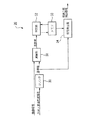
図2は、画像検出装置の駆動回路の構成を示したブロック図である。図2に示すように、黒表示検出部20は、画像処理部21に接続されており、黒表示部を検出すると、黒表示検出信号として画像処理部21に供給するようになっている。
まず、画像信号は、黒表示検出部20、画像処理部21および画像解析部24に入力される。黒表示検出部20は、入力された画像信号から黒表示部を検出し、黒表示部検出信号として画像処理部21に供給する。
【0024】
画像解析部24では、画像信号の解析を行って伸長係数、オフセット値、調光制御信号を算出し、画像制御信号として画像処理部21に供給する。
また、画像解析部24は、調光制御信号に基づいて調光素子ドライバ25を制御する。調光ドライバ25は、調光素子26を制御する。この調光素子ドライバ25は、画像処理部21によって各液晶ライトバルブ522、523、524に供給される画像信号の伸長有無に応じて、光源510からの照明光量を変化させる。これにより、表示画像の明るさ範囲を拡張しつつ、滑らかな階調表現を実現することができる。
【0025】
黒表示検出部20では、水平・垂直同期信号に基づいて、表示画像の画像信号の縦または横1ライン分の座標値を検知する。また、検知した縦または横1ライン分の画像信号の画像データを加算し、ラインごとに黒表示部であるか否かの判定を行う。そして、黒表示部であると判定した場合、黒表示部検出信号を発生する。
一方、画像処理部21は、画像信号に対して、オフセット処理、黒補正、伸長処理を行う。そして、黒補正または伸長処理した画像信号のどちらが適した信号であるかを、黒表示部検出信号に基づいて判断する。
【0026】
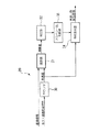
次に、第1の実施形態の黒表示検出部20の黒表示検出について、図3を参照しながら説明する。
図3は、第1の実施形態の黒表示検出部20の構成を示したブロック図である。この実施形態では、黒表示検出部20は、カウンタ30、演算部31、判定部32、メモリ33および信号発生器34を備えている。
カウンタ(座標検知手段)30は、水平・垂直同期信号を足すことにより、画像信号がどこまで入力されたか、すなわち1フレーム内の画像信号の座標値を作る。なお、ここでは横1ライン分の座標値を作る場合について説明する。
演算部(画像データ加算手段)31は、カウンタ30から供給される座標値に基づいて、横1ライン分の画像データを加算し、演算値として判定部32に供給する。
また、カウンタ30および演算部31は、入力された画像信号から表示領域を検出する表示領域検出手段としても機能する。
【0027】
判定部(判定手段)32は、演算部31から供給された演算値を所定の黒表示部判定基準との大小関係を判定することにより、黒表示部であるか否かを判定する。ここで、黒表示部判定基準とは、黒表示部であるか否かの判定基準値をいい、例えば、画像データを1とみなして横1ライン分全て足した値を基準値とすれば、横1ライン上の画像データのほとんどが0であるような場合、黒表示部だと判定できる。
この判定部32による判定結果、すなわち所定の横1ラインが黒表示部であるか否かの結果は、メモリ33に格納される。
【0028】
メモリ33は、判定部32からの判定結果を格納する。また、メモリ33は、1つ前のフレームの黒表示部の大きさが格納されており、黒表示部の大きさが変わったときに1フレーム内の黒表示部の座標値を更新する。
信号発生器(黒表示部検出手段)34は、カウンタ30からの座標値と、判定部32からの黒表示部であるか否かの判定結果に応じて、黒表示部検出信号を発生し、画像処理部21に供給する。なお、黒表示部検出手段34は、カウンタ30によって検知された座標に基づいて、検出された黒表示部が画面上下、または、画面左右のどちらの位置にあるかを検出する画面位置検出手段としても機能する。
【0029】
次に、第1の実施形態の画像処理部21について図4を参照しながら説明する。第1の実施形態の画像処理部21は、ラインメモリ40、オフセット処理部41、黒補正部42、伸長処理部43、判断部44を備えている。
ラインメモリ40は、検知された横1ラインの画像信号を格納する。なお、第1の実施形態では、黒表示検出部20は、1ライン分ずつの画像データに関して黒表示部であるか否かの判定を行うので、ラインメモリ40に1つ前の1ライン分の画像データが格納されていることになる。
【0030】
オフセット処理部41は、画像解析部24から供給されたオフセット値に基づいて、画像信号に対するオフセット処理、すなわち画像信号から所定の引き算量(オフセット値)を減算する。ここで、オフセット値とは、例えば、画像データの中で最も暗い値をいい、オフセット処理として画像信号に対してオフセット値だけ減算することにより、画像信号の不要な黒浮きを抑えられる値をいう。
【0031】
黒補正部(補正手段)42は、オフセット処理後の画像信号に対して、黒補正を行う。画像信号をV、伸長倍率をp、光抜け量をΔvとした場合、黒表示部の画像信号V´は
V´=V+(1−1/p)Δv
というような式で補正することができる。
ここで、光抜け量Δvとは、画像信号を0にしたときのスクリーン上の明るさをいう。より具体的には、図1の光源510からの光量を調光素子で遮断したのに、各液晶ライトバルブ522、523、524を全て暗表示とした状態でも、なおスクリーン上に漏れてくる光量のことをいう。
この光抜け量Δvは、出荷前の検査時に測定したものをデフォルトで記憶しておくようにしてもよいし、画像検出装置の電源入力時や立ち上げ時に測定して、記憶するようにしてもよい。
【0032】
このように補正することにより、例えば、面積の大きな黒表示部について、各液晶ライトバルブ522、523、524での表示が大きい場合、すなわち照明光量が最大の場合には(上記の式においてpが1の場合)、黒表示部を暗い表示に補正する。また、照明光量が小さい場合には、黒表示部を明るい表示に補正する。これにより、照明光量の変化と、黒表示部の変化が打ち消し合うことになり、黒表示部がチラツかない映像表示を行うことができる。
【0033】
伸長処理部43は、オフセット処理後の画像信号に対して、画像解析部24からの伸長係数に基づく伸長処理を行う。
判断部44は、黒表示検出部20からの黒表示部検出信号に基づいて、黒補正部42または伸長処理部43からの画像信号のどちらをライトバルブドライバ22に供給するか判断する。
【0034】
このように、第1の実施形態では、黒表示検出部20によって表示画像の画像信号のうち、黒表示部を検出し、黒表示部検出信号として画像処理部21に供給する。画像処理部21では、黒表示部検出信号に基づいて、黒表示部以外の画像信号に対する照明光量に応じた黒表示部の補正を行うことができる。これにより、黒表示部の明るさ変化を抑え、画像のチラツキを防止することができる。また、アスペクト比の異なる画像信号が入力された場合にも、画像信号のアスペクト比に対して柔軟な対応が可能となり、黒表示部の検出を正確に行うことができる。
【0035】
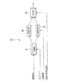
次に、第2の実施形態の黒表示検出部20の黒表示検出について、図5を参照しながら説明する。なお、図3の第1の実施形態の黒表示検出部と同様の構成部分については同じ番号を付し、適宜説明を省略する。また、第2の実施形態では、画像信号にアスペクト比の情報が含まれているものとする。
図5の黒表示検出部20は、図3の黒表示検出部20のメモリ33の替わりに、アスペクト比判断部35が追加された構成となっている。
【0036】
アスペクト比判断部(判断手段)35は、4:3、16:9などのアスペクト比(画面の縦横の比率)のパターンを、すなわち黒表示部である黒帯部分の1画面内での位置情報を格納しており、判断部32において黒表示部であると判断された所定の座標が、格納されている黒表示位置情報の範囲内であるかどうかを判断する。黒表示であると判断された画像データの座標が、あるアスペクト比における黒表示部の範囲内であれば、黒表示部であると判定する。例えば、映画のタイトルロールを表示する場合、画面全体が暗い中にタイトルなどの文字が表示されるので、黒表示部と誤判定されやすくなる。そこで、アスペクト比判断部35にあらかじめ格納されているいくつかのパターンと比較することにより、画像信号が小さいことによる誤判定を防止することができる。
【0037】
次に、第2の実施形態の画像処理部21について図6を参照しながら説明する。第2の実施形態の画像処理部21は、ラインメモリ40がない構成となっている点が第1の実施形態の画像処理部21と異なる。なお、図4の第1の実施形態の画像処理部と同様の構成部分については同じ番号を付し、適宜説明を省略する。
第2の実施形態では、黒表示検出部20がアスペクト比に基づいて、黒表示の判断を行うので、ラインメモリ40がない構成となっている。
【0038】
以上、本発明の一実施形態について説明してきたが、本発明は、上述の実施形態に限定されるものではない。
例えば、第1の実施形態では、横1ライン分の画像データについて判定するものとして説明したが、これに限られるものではない。カウンタ30において、縦1ライン分の画像データについて検知するようにしてもよい。縦1ライン分に関しての黒表示部の判定を行う場合、判定部32は、1フレーム分の演算値を格納してから判定するようになる。このように、縦1ラインに関しても黒表示判定するので、画面上下だけでなく、画面左右の黒帯部分も検出することができる。
なお、黒表示検出部20が縦1ライン分に基づいて検出を行う場合、1フレームごとの判定となるので、画像処理部21は、第2の実施形態のようにラインメモリ40がない構成となる。
【0039】
また、例えば、本実施の形態では、本発明の画像検出装置、画像検出方法および画像検出プログラムの利用が可能な画像表示装置として、投射型表示装置を用いて説明してきたが、これに限られるものではなく、例えば、直視型表示装置などでもよい。また、本発明の画像検出方法および画像検出プログラムは、LCD、エレクトロルミネッセンス、プラズマディスプレイ、デジタルミラーデバイス、フィールドエミッションデバイスなどの画像信号の処理にも用いることができる。
【図面の簡単な説明】
【図1】 投射型表示装置の一例を示した概略構成図。
【図2】 画像検出装置の駆動回路の構成図。
【図3】 第1の実施形態の黒表示検出部の構成図。
【図4】 第1の実施形態の画像処理部の構成図。
【図5】 第2の実施形態の黒表示検出部の構成図。
【図6】 第2の実施形態の画像処理部の構成図。
【符号の説明】
20 黒表示検出部、21 画像処理部、22 ライトバルブドライバ、24 画像解析部、25 調光素子ドライバ、26 調光素子、30 カウンタ、31演算部、32 判定部、33 メモリ、34 信号発生器、35 アスペクト比判断器、40 ラインメモリ、41 オフセット処理部、42 黒補正部、43 伸長処理部、44 判断部[0001]
BACKGROUND OF THE INVENTION
The present invention relates to an image detection device, an image detection method, an image detection program, and an image display device.
[0002]
[Prior art]
In recent years, with the advancement of IT technology, the need for image display devices is increasing in various fields. Among such image display devices, a liquid crystal display device that can change the optical characteristics by electrically controlling the arrangement of liquid crystal molecules is particularly expected from the viewpoints of low power consumption, thinness, and eye-friendlyness. Has been. In recent years, as one form of liquid crystal display device, a projection type liquid crystal display device (liquid crystal projector) that enlarges and projects an image emitted from an optical system using a liquid crystal light valve onto a screen through a projection lens has been widely used. It has become.
[0003]
This projection type liquid crystal display device uses a liquid crystal light valve as a light modulation means, but has a displayable brightness range (dynamic range) due to light leakage and stray light generated by various optical elements constituting the optical system. There are cases where it is difficult to improve the video quality. Therefore, as a method for expanding the dynamic range, a method has been conventionally proposed in which the amount of light incident on the light valve (light modulation means) is changed according to the video signal, while the image displayed on the light valve is expanded.
For example, there is a technique for adjusting an input video signal with a correlation between contrast adjustment (signal amplitude control) and luminance adjustment of a light source (backlight) (see, for example, Patent Document 1).
[0004]
[Patent Document 1]
Japanese Patent Laid-Open No. 2001-27890
[0005]
Recently, the aspect ratio of the screen has shifted to the wide type because the human field of view is long in the horizontal direction and it is suitable for the screen display of a long movie. When recording a wide-screen video with a 4: 3 aspect ratio (screen aspect ratio), a black band (black display) is created at the top and bottom of the screen, and the video screen is placed at the center. Used. At this time, when dimming is performed, the brightness of the black display portion is bright when the image displayed at the center is bright. As described above, the black display portion changes according to the video signal displayed at the center of the screen. Therefore, various methods for adjusting the contrast and the light source according to the video signal that changes as needed have been proposed.
[0006]
[Problems to be solved by the invention]
However, in the conventional technique, when there are two input video signals in advance, signal processing is performed on one input video signal and signal processing is not performed on the other input video signal, so that visual contrast is achieved. This is to improve the feeling and does not divide one input video signal into two.
For example, when a black display part is included in a series in the video signal, the video signal is adjusted as it is, so the black display part is also adjusted, and the video signal displayed at the center of the screen It will change according to.
[0007]
In addition, when video signals having different aspect ratios are input, black display is performed in an area where there is no video signal (letterbox). When dimming is performed in the adaptive dimming display system, the brightness of the black display portion changes, and a flicker is felt. To prevent this flickering, when there are multiple display areas in one screen, dimming is performed according to the display image signal displayed in the main display area, and image processing is performed to cancel dimming in the other areas. Sometimes.
However, many actual video signals include a black display portion, and it is necessary to detect the black display portion in order to suppress flicker.
[0008]
The present invention has been made in view of the above circumstances, and by detecting the black display portion from the image signal of the display image and correcting the detected black display portion according to the amount of illumination light, the brightness of the black display portion is improved. An object of the present invention is to provide an image detection device, an image detection method, an image detection program, and an image display device capable of suppressing changes and suppressing image flicker.
[0009]
[Means for Solving the Problems]
An image detection apparatus according to the present invention is an image detection apparatus that detects a black display portion of a display image, and includes a display area detection unit that detects a display area from an image signal, and a black display portion of the detected display area. And a black position detection means for detecting whether the detected black display portion is located on the top and bottom of the screen or on the left and right of the screen.
As described above, since the black display portion can be accurately detected from the image signals of the display image, the black display portion can be corrected in accordance with the illumination light amount for the image signals other than the black display portion. Thereby, the brightness change of a black display part can be suppressed and the flicker of a black display part can be prevented.
[0010]
The image detection apparatus of the present invention is an image detection apparatus that detects a black display portion of a display image, and detects the coordinates of the image signal during a unit period based on the vertical and horizontal synchronization signals of the image signal of the display image. Black display of pixel data on one line added by the pixel detection means, pixel data addition means for adding pixel data on one line including the coordinates detected by the coordinate value detection means, and pixel data addition means A determination unit that determines a magnitude relationship with respect to the image reference, and a black display unit detection that determines that the coordinates of the image data belong to the black display unit according to a determination result of the image data with respect to the black display unit reference Means.
[0011]
As described above, since the black display portion can be accurately detected from the image signals of the display image, the black display portion can be corrected in accordance with the illumination light amount for the image signals other than the black display portion. Thereby, the brightness change of a black display part can be suppressed and the flicker of a black display part can be prevented. Further, even when image signals having different aspect ratios are input, it is possible to flexibly cope with the aspect ratio of the image signals, and the black display portion can be accurately detected.
In the image detection apparatus of the present invention, the determination unit performs the determination after storing image data for one frame.
Thus, since black display determination is performed for one vertical line, not only the top and bottom of the screen but also the black belt portions on the left and right of the screen can be detected.
[0012]
The image detection apparatus of the present invention is an image detection apparatus that detects a black display portion of a display image, and detects the coordinates of the image signal based on the vertical and horizontal synchronization signals of the image signal of the display image. Means, image data adding means for adding image data of coordinates detected by the coordinate detecting means, and determining means for determining a magnitude relationship with respect to a black display unit reference of pixel data added by the image data adding means; An aspect ratio determination unit that determines whether the image data has a predetermined aspect ratio according to a determination result of the image data with respect to a black display unit reference by the determination unit, and a black display range by the aspect ratio determination unit. And a black display part detecting means for detecting that the image signal of the coordinate is a black display part.
As described above, the image detection apparatus according to the present invention compares with the stored aspect ratio, so that, for example, when a character such as a title is displayed while the entire screen is dark like a title roll of a movie, An erroneous determination of the display unit can be prevented.
[0013]
In addition, the image detection apparatus of the present invention further includes a correction unit that performs black display correction of the image signal based on detection by the black display unit detection unit.
As described above, correction is performed based on detection of the black display portion. For example, when the illumination light amount is maximum, the black display portion is corrected to dark display, and when the illumination light amount is small, black display is performed. It is possible to correct the portion to a bright display. As a result, the change in the amount of illumination light and the change in the black display portion cancel each other, and video display can be performed while preventing flickering.
[0014]
The image detection method of the present invention is an image detection method for detecting a black display portion of a display image, and includes a first step of detecting a display region from an image signal, and a display region detected in the first step. Of these, a second step of detecting the black display portion and a third step of detecting whether the black display portion detected in the second step is located on the top and bottom of the screen or on the left and right of the screen. It is characterized by having.
The image detection method of the present invention is an image detection method for detecting a black display portion of a display image, wherein the coordinates of the image signal during a unit period are determined based on the vertical and horizontal synchronization signals of the image signal of the display image. A first step to detect, a second step to add pixel data on one line including the coordinates detected in the first step, and pixel data on one line added in the second step A third step of determining a magnitude relationship with respect to the black display unit reference and a determination result of the image data with respect to the black display unit reference according to the third step, the coordinates of the image data belong to the black display unit And a fourth step of judging.
[0015]
The image detection method of the present invention is an image detection method for detecting a black display portion of a display image, and is a first method for detecting coordinates of an image signal based on vertical / horizontal synchronization signals of the image signal of the display image. A second step of adding the image data of the coordinates detected in the first step, and a third step of determining the magnitude relationship with respect to the black display unit reference of the pixel data added in the second step And a fourth step of determining whether or not the coordinates of the image data have a predetermined aspect ratio according to the determination result of the image data with respect to the black display unit reference in the third step, And a fifth step of detecting that the image signal of the coordinate value is a black display portion when it is determined in step 4 that it is within the black display range.
[0016]
An image detection program according to the present invention is an image detection program for detecting a black display portion of a display image, and includes a display region detection function for detecting a display region from an image signal, and a black display portion of the detected display regions. The computer is caused to function as a black display portion detection function for detecting, and a screen position detection function for detecting whether the detected black display portion is located on the top or bottom of the screen or on the left or right of the screen.
The image detection program of the present invention is an image detection program for detecting a black display portion of a display image, and the coordinates of the image signal during a unit period are determined based on the vertical / horizontal synchronization signal of the image signal of the display image. Coordinate detection function to detect, pixel data addition function to add pixel data on one line including coordinates detected by the coordinate detection function, black display portion of pixel data on one line added by the pixel data addition function A determination function for determining a magnitude relationship with respect to a reference, a black display portion detection function for determining that the coordinates of the image data belong to a black display portion according to a determination result of the image data with respect to the black display portion reference by the determination function It is characterized by making a computer function.
[0017]
The image detection program of the present invention is an image detection program for detecting a black display portion of a display image, and a coordinate detection function for detecting the coordinates of the image signal based on the vertical / horizontal synchronization signal of the image signal of the display image, An image data addition function for adding image data of coordinates detected by the coordinate detection function, a determination function for determining a magnitude relationship with respect to a black display unit reference of pixel data added by the image data addition function, and the determination function by the determination function An aspect ratio determination function that determines whether or not the coordinates of the image data have a predetermined aspect ratio according to a determination result with respect to the black display unit reference of the image data, and that the aspect ratio determination function determines that the image data is within the black display range. The computer functions as a black display detection function for detecting that the image signal at the coordinates is a black display. And wherein the Rukoto.
In addition, an image display device of the present invention includes any one of the above image detection devices.
[0018]
DETAILED DESCRIPTION OF THE INVENTION
Hereinafter, preferred embodiments of an image detection apparatus, an image detection method, and an image detection program of the present invention will be described in detail with reference to FIGS. 1 to 6.
As an example of an image display device including an image detection device using the image detection method of the present invention, a three-plate projection display device including a liquid crystal light valve for each of different colors of RGB will be described.
FIG. 1 is a schematic configuration diagram illustrating an example of a projection display device. As shown in FIG. 1, the projection display device includes a
The
[0019]
The
The blue light / green light reflecting
[0020]
On the other hand, the green light reflected by the
The blue light reflected by the
[0021]
The three color lights modulated by the liquid crystal
[0022]
Each of the liquid crystal
In the image detection apparatus according to the present embodiment, the black display detection unit detects the black display unit of the image signal of the display image, performs predetermined image processing on the detected black display unit by the image processing unit, and displays the image. Is to do. Note that the image detection apparatus includes a black display detection unit, which will be described later, or a black display detection unit and an image processing unit.
[0023]
Here, an image detection method of the image detection apparatus according to the present embodiment will be described.
FIG. 2 is a block diagram showing the configuration of the drive circuit of the image detection apparatus. As shown in FIG. 2, the black
First, the image signal is input to the black
[0024]
The
The
[0025]
The black
On the other hand, the
[0026]
Next, black display detection of the black
FIG. 3 is a block diagram illustrating a configuration of the black
The counter (coordinate detection means) 30 adds up the horizontal / vertical synchronization signal to create the coordinate value of the image signal within one frame, that is, how far the image signal has been input. Here, a case where coordinate values for one horizontal line are created will be described.
The computing unit (image data adding means) 31 adds the image data for one horizontal line based on the coordinate value supplied from the
The
[0027]
The determination unit (determination means) 32 determines whether or not it is a black display unit by determining the magnitude relationship between the calculation value supplied from the
A determination result by the
[0028]
The
The signal generator (black display part detection means) 34 generates a black display part detection signal according to the coordinate value from the
[0029]
Next, the
The
[0030]
Based on the offset value supplied from the
[0031]
The black correction unit (correction unit) 42 performs black correction on the image signal after the offset processing. When the image signal is V, the expansion magnification is p, and the amount of light loss is Δv, the image signal V ′ of the black display portion is
V ′ = V + (1-1 / p) Δv
It can be corrected by such an expression.
Here, the light omission amount Δv means the brightness on the screen when the image signal is set to zero. More specifically, although the light amount from the
The light leakage amount Δv may be stored by default as measured at the time of inspection before shipment, or may be measured and stored at the time of power input or startup of the image detection apparatus. Good.
[0032]
By correcting in this way, for example, when the display on each of the liquid crystal
[0033]
The
The
[0034]
As described above, in the first embodiment, the black
[0035]
Next, black display detection of the black
The black
[0036]
The aspect ratio determination unit (determination means) 35 displays the pattern of the aspect ratio (ratio of the aspect ratio of the screen) such as 4: 3, 16: 9, that is, position information within one screen of the black belt portion which is the black display portion. Is determined, and it is determined whether the predetermined coordinates determined by the
[0037]
Next, the
In the second embodiment, since the black
[0038]
Although one embodiment of the present invention has been described above, the present invention is not limited to the above-described embodiment.
For example, although the first embodiment has been described as determining image data for one horizontal line, the present invention is not limited to this. The
Note that when the black
[0039]
For example, in the present embodiment, the projection display device has been described as the image display device that can use the image detection device, the image detection method, and the image detection program of the present invention. However, the present invention is not limited to this. For example, a direct-view display device may be used. The image detection method and image detection program of the present invention can also be used for processing image signals of LCDs, electroluminescence, plasma displays, digital mirror devices, field emission devices, and the like.
[Brief description of the drawings]
FIG. 1 is a schematic configuration diagram illustrating an example of a projection display device.
FIG. 2 is a configuration diagram of a drive circuit of the image detection apparatus.
FIG. 3 is a configuration diagram of a black display detection unit according to the first embodiment.
FIG. 4 is a configuration diagram of an image processing unit according to the first embodiment.
FIG. 5 is a configuration diagram of a black display detection unit according to the second embodiment.
FIG. 6 is a configuration diagram of an image processing unit according to the second embodiment.
[Explanation of symbols]
20 black display detection unit, 21 image processing unit, 22 light valve driver, 24 image analysis unit, 25 dimming element driver, 26 dimming element, 30 counter, 31 calculation unit, 32 determination unit, 33 memory, 34
Claims (11)
画像信号から表示領域を検出する表示領域検出手段と、
前記検出された表示領域のうち、黒表示部を検出する黒表示部検出手段と、
前記検出された黒表示部が画面上下、または、画面左右のどちらの位置にあるかを検出する画面位置検出手段と、
前記黒表示部検出手段による検出に基づいて、画像信号の黒表示補正を行う補正手段とを備え、
前記補正手段は、光抜け量を用いて黒表示補正を行うことを特徴とする画像検出装置。An image detection device for detecting a black display portion of a display image,
Display area detecting means for detecting the display area from the image signal;
Of the detected display areas, a black display part detecting means for detecting a black display part;
Screen position detecting means for detecting whether the detected black display portion is located on the top or bottom of the screen or on the left or right of the screen;
Correction means for performing black display correction of an image signal based on detection by the black display section detection means,
The image detecting apparatus according to claim 1, wherein the correction unit performs black display correction using an amount of light leakage .
表示画像の画像信号の垂直・水平同期信号に基づいて、単位期間中の画像信号を検知する座標検知手段と、
前記座標検知手段によって検知された座標を含む1ライン上の画素データを加算する画素データ加算手段と、
前記画素データ加算手段で加算された1ライン上の画素データの黒表示部基準に対する大小関係を判定する判定手段と、
前記判定手段による前記画像データの前記黒表示部基準に対する判定結果に応じて、当該画像データの座標が黒表示部に属すると判断する黒表示部検出手段と、
前記黒表示部検出手段による検出に基づいて、画像信号の黒表示補正を行う補正手段とを備え、
前記補正手段は、光抜け量を用いて黒表示補正を行うことを特徴とする画像検出装置。An image detection device for detecting a black display portion of a display image,
Coordinate detection means for detecting an image signal during a unit period based on a vertical / horizontal synchronization signal of an image signal of a display image;
Pixel data adding means for adding pixel data on one line including the coordinates detected by the coordinate detecting means;
Determining means for determining a magnitude relationship with respect to a black display unit reference of pixel data on one line added by the pixel data adding means;
A black display unit detecting unit that determines that the coordinates of the image data belong to a black display unit according to a determination result of the image data with respect to the black display unit reference by the determination unit;
Correction means for performing black display correction of an image signal based on detection by the black display section detection means,
The image detecting apparatus according to claim 1, wherein the correction unit performs black display correction using an amount of light leakage .
表示画像の画像信号の垂直・水平同期信号に基づいて、画像信号の座標を検知する座標検知手段と、
前記座標値検知手段によって検知された座標の画像データを加算する画像データ加算手段と、
前記画像データ加算手段で加算された画素データの黒表示部基準に対する大小関係を判定する判定手段と、
前記判定手段による前記画像データの黒表示部基準に対する判定結果に応じて、当該画像データが所定のアスペクト比であるかどうかを判断するアスペクト比判断手段と、
前記アスペクト比判断手段によって黒表示範囲内であると判断された場合、当該座標の画像信号が黒表示部であると検出する黒表示部検出手段と、
前記黒表示部検出手段による検出に基づいて、画像信号の黒表示補正を行う補正手段とを備え、
前記補正手段は、光抜け量を用いて黒表示補正を行うことを特徴とする画像検出装置。An image detection device for detecting a black display portion of a display image,
Coordinate detection means for detecting the coordinates of the image signal based on the vertical and horizontal synchronization signals of the image signal of the display image;
Image data adding means for adding image data of coordinates detected by the coordinate value detecting means;
Determining means for determining a magnitude relationship with respect to a black display unit reference of the pixel data added by the image data adding means;
Aspect ratio determining means for determining whether or not the image data has a predetermined aspect ratio according to a determination result of the image data with respect to a black display unit reference by the determining means;
A black display portion detecting means for detecting that the image signal at the coordinates is a black display portion when the aspect ratio determining means determines that the image signal is within the black display range;
Correction means for performing black display correction of an image signal based on detection by the black display section detection means,
The image detecting apparatus according to claim 1, wherein the correction unit performs black display correction using an amount of light leakage .
画像信号から表示領域を検出する第1のステップと、
前記第1のステップで検出された表示領域のうち、黒表示部を検出する第2のステップと、
前記第2のステップで検出された黒表示部が画面上下、または、画面左右のどちらの位置にあるかを検出する第3のステップと、
前記第2のステップによる検出に基づいて、画像信号の黒表示補正を光抜け量を用いて行う第4のステップと、
を有することを特徴とする画像検出方法。An image detection method for detecting a black display portion of a display image,
A first step of detecting a display area from the image signal;
Of the display areas detected in the first step, a second step of detecting a black display portion;
A third step of detecting whether the black display portion detected in the second step is located on the top and bottom of the screen or on the left and right of the screen;
A fourth step of performing black display correction of the image signal using the amount of light omission based on the detection in the second step;
An image detection method characterized by comprising:
表示画像の画像信号の垂直・水平同期信号に基づいて、単位期間中の画像信号の座標を検知する第1のステップと、
前記第1のステップで検知された座標を含む1ライン上の画素データを加算する第2のステップと、
前記第2のステップで加算された1ライン上の画素データの黒表示部基準に対する大小関係を判定する第3のステップと、
前記第3のステップによる前記画像データの前記黒表示部基準に対する判定結果に応じて、当該画像データの座標が黒表示部に属すると判断する第4のステップと、
前記第4のステップによる検出に基づいて、画像信号の黒表示補正を光抜け量を用いて行う第5のステップと、
を有することを特徴とする画像検出方法。An image detection method for detecting a black display portion of a display image,
A first step of detecting coordinates of the image signal during the unit period based on the vertical / horizontal synchronization signal of the image signal of the display image;
A second step of adding pixel data on one line including the coordinates detected in the first step;
A third step of determining a magnitude relationship with respect to a black display unit reference of pixel data on one line added in the second step;
A fourth step of determining that the coordinates of the image data belong to a black display unit according to a determination result of the image data with respect to the black display unit reference in the third step;
A fifth step of performing black display correction of the image signal using the amount of light omission based on the detection in the fourth step;
An image detection method characterized by comprising:
表示画像の画像信号の垂直・水平同期信号に基づいて、画像信号の座標を検知する第1のステップと、
前記第1のステップで検知された座標の画像データを加算する第2のステップと、
前記第2のステップで加算された画素データの黒表示部基準に対する大小関係を判定する第3のステップと、
前記第3のステップによる前記画像データの黒表示部基準に対する判定結果に応じて、当該画像データが所定のアスペクト比の範囲内であるかどうかを判断する第4のステップと、
前記第4のステップで黒表示範囲内であると判断された場合、当該座標値の画像信号が黒表示部であると検出する第5のステップと、
前記第4のステップによる検出に基づいて、画像信号の黒表示補正を光抜け量を用いて行う第5のステップと、
を有することを特徴とする画像検出方法。An image detection method for detecting a black display portion of a display image,
A first step of detecting the coordinates of the image signal based on the vertical / horizontal synchronization signal of the image signal of the display image;
A second step of adding the image data of the coordinates detected in the first step;
A third step of determining the magnitude relationship of the pixel data added in the second step with respect to the black display unit reference;
A fourth step of determining whether the image data is within a predetermined aspect ratio according to a determination result of the image data with respect to a black display unit reference in the third step;
A fifth step of detecting that the image signal of the coordinate value is a black display unit when it is determined in the fourth step that it is within the black display range;
A fifth step of performing black display correction of the image signal using the amount of light omission based on the detection in the fourth step;
An image detection method characterized by comprising:
画像信号から表示領域を検出する表示領域検出機能、
前記検出された表示領域のうち、黒表示部を検出する黒表示部検出機能、
前記検出された黒表示部が画面上下、または、画面左右のどちらの位置にあるかを検出する画面位置検出機能、
前記黒表示部検出機能による検出に基づいて、画像信号の黒表示補正を光抜け量を用いて行う補正機能としてコンピュータを機能させることを特徴とする画像検出プログラム。An image detection program for detecting a black display portion of a display image,
Display area detection function to detect the display area from the image signal,
Among the detected display areas, a black display part detection function for detecting a black display part,
A screen position detection function for detecting whether the detected black display portion is located on the top or bottom of the screen or on the left or right of the screen;
An image detection program for causing a computer to function as a correction function for performing black display correction of an image signal using a light omission amount based on detection by the black display portion detection function .
表示画像の画像信号の垂直・水平同期信号に基づいて、単位期間中の画像信号の座標を検知する座標値検知機能、
前記座標値検知機能によって検知された座標を含む1ライン上の画素データを加算する画素データ加算機能、
前記画素データ加算機能によって加算された1ライン上の画素データの黒表示部基準に対する大小関係を判定する判定機能、
前記判定機能による前記画像データの前記黒表示部基準に対する判定結果に応じて、当該画像データの座標が黒表示部に属すると判断する黒表示部検出機能、
前記黒表示部検出機能による検出に基づいて、画像信号の黒表示補正を光抜け量を用いて行う補正機能としてコンピュータを機能させることを特徴とする画像検出プログラム。An image detection program for detecting a black display portion of a display image,
A coordinate value detection function that detects the coordinates of the image signal during the unit period based on the vertical / horizontal synchronization signal of the image signal of the display image,
A pixel data addition function for adding pixel data on one line including the coordinates detected by the coordinate value detection function;
A determination function for determining a magnitude relationship with respect to a black display unit reference of pixel data on one line added by the pixel data addition function;
A black display unit detection function for determining that the coordinates of the image data belong to a black display unit according to a determination result of the image data with respect to the black display unit reference by the determination function;
An image detection program for causing a computer to function as a correction function for performing black display correction of an image signal using a light omission amount based on detection by the black display portion detection function .
表示画像の画像信号の垂直・水平同期信号に基づいて、画像信号の座標を検知する座標検知機能、
前記座標検知機能によって検知された座標の画像データを加算する画像データ加算機能、
前記画像データ加算機能によって加算された画素データの黒表示部基準に対する大小関係を判定する判定機能、
前記判定機能による前記画像データの黒表示部基準に対する判定結果に応じて、当該画像データが所定のアスペクト比であるかどうかを判断するアスペクト判断機能、
前記アスペクト判断機能によって黒表示範囲内であると判断された場合、当該座標の画像信号が黒表示部であると検出する黒表示部検出機能、
前記黒表示部検出機能による検出に基づいて、画像信号の黒表示補正を光抜け量を用いて行う補正機能としてコンピュータを機能させることを特徴とする画像検出プログラム。An image detection program for detecting a black display portion of a display image,
A coordinate detection function that detects the coordinates of the image signal based on the vertical / horizontal synchronization signal of the image signal of the display image,
An image data addition function for adding image data of coordinates detected by the coordinate detection function;
A determination function for determining a magnitude relationship with respect to a black display unit reference of pixel data added by the image data addition function;
An aspect determination function for determining whether the image data has a predetermined aspect ratio according to a determination result of the image data with respect to a black display unit reference by the determination function;
A black display detection function for detecting that the image signal of the coordinates is a black display when the aspect determination function determines that the image is within the black display range;
An image detection program for causing a computer to function as a correction function for performing black display correction of an image signal using a light omission amount based on detection by the black display portion detection function .
Priority Applications (1)
| Application Number | Priority Date | Filing Date | Title |
|---|---|---|---|
| JP2002332083A JP4200742B2 (en) | 2002-11-15 | 2002-11-15 | Image detection apparatus, image detection method, image detection program, and image display apparatus |
Applications Claiming Priority (1)
| Application Number | Priority Date | Filing Date | Title |
|---|---|---|---|
| JP2002332083A JP4200742B2 (en) | 2002-11-15 | 2002-11-15 | Image detection apparatus, image detection method, image detection program, and image display apparatus |
Publications (2)
| Publication Number | Publication Date |
|---|---|
| JP2004163809A JP2004163809A (en) | 2004-06-10 |
| JP4200742B2 true JP4200742B2 (en) | 2008-12-24 |
Family
ID=32809264
Family Applications (1)
| Application Number | Title | Priority Date | Filing Date |
|---|---|---|---|
| JP2002332083A Expired - Fee Related JP4200742B2 (en) | 2002-11-15 | 2002-11-15 | Image detection apparatus, image detection method, image detection program, and image display apparatus |
Country Status (1)
| Country | Link |
|---|---|
| JP (1) | JP4200742B2 (en) |
Families Citing this family (8)
| Publication number | Priority date | Publication date | Assignee | Title |
|---|---|---|---|---|
| TWI249959B (en) | 2003-05-16 | 2006-02-21 | Seiko Epson Corp | Image processing system, projector, information memorizing medium and image processing method |
| KR101183399B1 (en) | 2006-03-31 | 2012-09-14 | 엘지디스플레이 주식회사 | Display and Driving Method thereof |
| JP4222380B2 (en) | 2006-04-12 | 2009-02-12 | ソニー株式会社 | Image processing apparatus and method, recording medium, and program |
| JP2008116554A (en) * | 2006-11-01 | 2008-05-22 | Sharp Corp | Backlight control device and video display device equipped with the backlight control device |
| KR101332107B1 (en) | 2006-12-29 | 2013-11-21 | 엘지디스플레이 주식회사 | Liquid crystal display device and method driving of the same |
| JP5293574B2 (en) * | 2009-11-18 | 2013-09-18 | 船井電機株式会社 | Video display device and television |
| WO2011121630A1 (en) * | 2010-03-29 | 2011-10-06 | Necディスプレイソリューションズ株式会社 | Correction method and display device |
| JP6428501B2 (en) * | 2015-06-24 | 2018-11-28 | 株式会社Jvcケンウッド | Video signal processing apparatus and projection display apparatus |
-
2002
- 2002-11-15 JP JP2002332083A patent/JP4200742B2/en not_active Expired - Fee Related
Also Published As
| Publication number | Publication date |
|---|---|
| JP2004163809A (en) | 2004-06-10 |
Similar Documents
| Publication | Publication Date | Title |
|---|---|---|
| US7683912B2 (en) | Image display apparatus, image display method and computer-readable recording medium storing image display program | |
| JP3876780B2 (en) | Image display device, image display method, and computer-readable recording medium on which image display program is recorded | |
| US20080036872A1 (en) | Image processing system, display device, program, and information recording medium | |
| TWI232956B (en) | Illuminator, projection display device and method for driving the same | |
| US7768688B2 (en) | Image display device, image display method, and image display program | |
| JP4956932B2 (en) | Image display device and image display method | |
| US7809209B2 (en) | Image display device, and control method for the same | |
| JP2002311503A (en) | Picture quality correction system | |
| US20030142275A1 (en) | Projection type display, a display and a drive method thereof | |
| US7530695B2 (en) | Projector | |
| JP2002366121A (en) | Video display device and video display method | |
| JP2003131322A (en) | Illuminator and projection type display device and method of driving the same | |
| JP2004163518A (en) | Device and method for image display | |
| US20100165193A1 (en) | Image processor, image display device, and image processing method | |
| JP4200742B2 (en) | Image detection apparatus, image detection method, image detection program, and image display apparatus | |
| JP6119155B2 (en) | Light control device, image display device, light control method and program | |
| JP2005107019A (en) | Image display method and system, and projector | |
| JP2002351445A (en) | Display device | |
| JP4114466B2 (en) | Image display device, image display method, and projection display device | |
| KR20050084248A (en) | Projection system with contrast homogeneity correction | |
| JP4776875B2 (en) | Video display device, projection display device | |
| JP2014048527A (en) | Image processing device, image display device, image processing method and program | |
| JP2008292904A (en) | Image display device, its driving method and electronic equipment | |
| JP2798169B2 (en) | Image display method and apparatus | |
| JP4862866B2 (en) | Image display device and image display method |
Legal Events
| Date | Code | Title | Description |
|---|---|---|---|
| A621 | Written request for application examination |
Free format text: JAPANESE INTERMEDIATE CODE: A621 Effective date: 20050318 |
|
| A521 | Written amendment |
Free format text: JAPANESE INTERMEDIATE CODE: A821 Effective date: 20050323 |
|
| A977 | Report on retrieval |
Free format text: JAPANESE INTERMEDIATE CODE: A971007 Effective date: 20080227 |
|
| A131 | Notification of reasons for refusal |
Free format text: JAPANESE INTERMEDIATE CODE: A131 Effective date: 20080610 |
|
| A521 | Written amendment |
Free format text: JAPANESE INTERMEDIATE CODE: A523 Effective date: 20080811 |
|
| TRDD | Decision of grant or rejection written | ||
| A01 | Written decision to grant a patent or to grant a registration (utility model) |
Free format text: JAPANESE INTERMEDIATE CODE: A01 Effective date: 20080916 |
|
| A01 | Written decision to grant a patent or to grant a registration (utility model) |
Free format text: JAPANESE INTERMEDIATE CODE: A01 |
|
| A61 | First payment of annual fees (during grant procedure) |
Free format text: JAPANESE INTERMEDIATE CODE: A61 Effective date: 20080929 |
|
| R150 | Certificate of patent or registration of utility model |
Free format text: JAPANESE INTERMEDIATE CODE: R150 |
|
| FPAY | Renewal fee payment (event date is renewal date of database) |
Free format text: PAYMENT UNTIL: 20111017 Year of fee payment: 3 |
|
| FPAY | Renewal fee payment (event date is renewal date of database) |
Free format text: PAYMENT UNTIL: 20121017 Year of fee payment: 4 |
|
| FPAY | Renewal fee payment (event date is renewal date of database) |
Free format text: PAYMENT UNTIL: 20121017 Year of fee payment: 4 |
|
| FPAY | Renewal fee payment (event date is renewal date of database) |
Free format text: PAYMENT UNTIL: 20131017 Year of fee payment: 5 |
|
| S531 | Written request for registration of change of domicile |
Free format text: JAPANESE INTERMEDIATE CODE: R313531 |
|
| R350 | Written notification of registration of transfer |
Free format text: JAPANESE INTERMEDIATE CODE: R350 |
|
| LAPS | Cancellation because of no payment of annual fees |