JP6117237B2 - Support core for cold shrink tube - Google Patents
Support core for cold shrink tube Download PDFInfo
- Publication number
- JP6117237B2 JP6117237B2 JP2014549198A JP2014549198A JP6117237B2 JP 6117237 B2 JP6117237 B2 JP 6117237B2 JP 2014549198 A JP2014549198 A JP 2014549198A JP 2014549198 A JP2014549198 A JP 2014549198A JP 6117237 B2 JP6117237 B2 JP 6117237B2
- Authority
- JP
- Japan
- Prior art keywords
- support core
- ribbon
- length
- core
- tubular support
- Prior art date
- Legal status (The legal status is an assumption and is not a legal conclusion. Google has not performed a legal analysis and makes no representation as to the accuracy of the status listed.)
- Active
Links
Images


Classifications
-
- B—PERFORMING OPERATIONS; TRANSPORTING
- B32—LAYERED PRODUCTS
- B32B—LAYERED PRODUCTS, i.e. PRODUCTS BUILT-UP OF STRATA OF FLAT OR NON-FLAT, e.g. CELLULAR OR HONEYCOMB, FORM
- B32B1/00—Layered products having a general shape other than plane
- B32B1/08—Tubular products
-
- H—ELECTRICITY
- H02—GENERATION; CONVERSION OR DISTRIBUTION OF ELECTRIC POWER
- H02G—INSTALLATION OF ELECTRIC CABLES OR LINES, OR OF COMBINED OPTICAL AND ELECTRIC CABLES OR LINES
- H02G15/00—Cable fittings
- H02G15/08—Cable junctions
- H02G15/18—Cable junctions protected by sleeves, e.g. for communication cable
- H02G15/182—Cable junctions protected by sleeves, e.g. for communication cable held in expanded condition in radial direction prior to installation
- H02G15/1826—Cable junctions protected by sleeves, e.g. for communication cable held in expanded condition in radial direction prior to installation on a removable hollow core, e.g. a tube
- H02G15/1833—Cable junctions protected by sleeves, e.g. for communication cable held in expanded condition in radial direction prior to installation on a removable hollow core, e.g. a tube formed of helically wound strip with adjacent windings, which are removable by applying a pulling force to a strip end
-
- Y—GENERAL TAGGING OF NEW TECHNOLOGICAL DEVELOPMENTS; GENERAL TAGGING OF CROSS-SECTIONAL TECHNOLOGIES SPANNING OVER SEVERAL SECTIONS OF THE IPC; TECHNICAL SUBJECTS COVERED BY FORMER USPC CROSS-REFERENCE ART COLLECTIONS [XRACs] AND DIGESTS
- Y10—TECHNICAL SUBJECTS COVERED BY FORMER USPC
- Y10T—TECHNICAL SUBJECTS COVERED BY FORMER US CLASSIFICATION
- Y10T428/00—Stock material or miscellaneous articles
- Y10T428/13—Hollow or container type article [e.g., tube, vase, etc.]
- Y10T428/1328—Shrinkable or shrunk [e.g., due to heat, solvent, volatile agent, restraint removal, etc.]
-
- Y—GENERAL TAGGING OF NEW TECHNOLOGICAL DEVELOPMENTS; GENERAL TAGGING OF CROSS-SECTIONAL TECHNOLOGIES SPANNING OVER SEVERAL SECTIONS OF THE IPC; TECHNICAL SUBJECTS COVERED BY FORMER USPC CROSS-REFERENCE ART COLLECTIONS [XRACs] AND DIGESTS
- Y10—TECHNICAL SUBJECTS COVERED BY FORMER USPC
- Y10T—TECHNICAL SUBJECTS COVERED BY FORMER US CLASSIFICATION
- Y10T428/00—Stock material or miscellaneous articles
- Y10T428/13—Hollow or container type article [e.g., tube, vase, etc.]
- Y10T428/1352—Polymer or resin containing [i.e., natural or synthetic]
- Y10T428/139—Open-ended, self-supporting conduit, cylinder, or tube-type article
- Y10T428/1393—Multilayer [continuous layer]
Description
本発明は全体的に、例えば、電気ケーブルのカバーとして、適用される弾性的に収縮可能なスリーブの支持のための、取り外し可能な管状支持コアアセンブリに関する。 The present invention relates generally to a removable tubular support core assembly for supporting an elastically shrinkable sleeve applied, for example, as a cover for an electrical cable.
エラストマーのカバー、又はスリーブ、及び取り外し可能な支持コアアセンブリは、当該技術分野において既知であり、配電分野において特に有用である。アセンブリは典型的には、熱の適用によって収縮し得るポリマーのチューブと区別するために、常温収縮チューブと称される。 Elastomeric covers or sleeves and removable support core assemblies are known in the art and are particularly useful in the power distribution field. The assembly is typically referred to as a cold shrink tube to distinguish it from a polymer tube that can shrink upon application of heat.
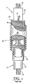
図1は、常温収縮チューブ接続部、又はスプライスアセンブリの典型的な使用法、及び構成を例示し、撚り合わせた導電体12、及び絶縁カバー13を含む、2つのケーブル端部11を示す。絶縁カバー13は、導電体12の端部を露出するように一部を切り取られ、この端部はひいては、固定ネジ保持具を備える、典型的には圧迫された若しくは窪んだ金属スリーブ、又は嵌合金属チューブからなり得る、好適な手段20によって、エンドツーエンド構成で一緒に接合される。接続部又はスプライスは、絶縁マスチック又はテープ(明確に例示するためにここでは省略される)で被覆され得る。
FIG. 1 illustrates a typical use and configuration of a cold shrink tube connection, or splice assembly, and shows two
支持コア15上で、半径方向に拡張又は伸張した状態の、常温収縮チューブ18を含む常温収縮チューブアセンブリは、スプライスを形成するように2つの導電体を接合する前に、ケーブル端部の一方の上で滑らされる。スプライスが完成した後、アセンブリはスプライス領域の上の適所へと摺動されて、支持コアが外されて、常温収縮チューブがスプライス周囲で収縮して、緊密なフィットを形成できるようにする。支持コア15は、その全長に沿って螺旋状に溝を有する中実コア、又は螺旋状に巻かれる接着された連続的なリボンであり得る、一体型管状コアであってもよく、溝又は接着線16により、孔を通じて取り外される連続的なストリップ17として支持コア15が引き出されるのを可能にする(すなわち、支持コア15とケーブル11との間から)。ストリップ17が徐々に引かれると、常温収縮チューブ18は、ぴったりと適合し、緊密に保持された保護カバーを形成するように、端部19でケーブルの周囲で収縮する。
A cold shrink tube assembly, including cold shrink tube 18, radially expanded or stretched on support
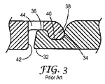
図2及び図3に示されるように、ある種類のりボン30は、管状のコアを形成するようにリボン30が螺旋状に巻かれる際に、凹部40及び42が連結突起部36及び38を受容するときに相互連結する、縁部32及び34を含む。相互連結縁部32、及び34は、接着剤、熱溶接、超音波溶接、又は溶媒溶接などの手段によって接合されてもよく、それにより、支持コア15のフープ強度が、常温収縮チューブ18の圧縮力に十分に抵抗する。コアのフープ強度は、主にリボン30の強度から、次に支持コア15の周囲方向に沿ってリボン30を接続する接続部の強度から得られる。典型的に接続部は、接続部を破壊してストリップ17を外すために、ストリップ17に大きな力が継続的に適用されなくてはならないように、十分な強度である。支持コア15の長さに沿って接続部の全部を破壊し、ストリップ17を常温収縮チューブ18の外に誘導するために、反復的な動作が必要とされる。
As shown in FIGS. 2 and 3, one type of
リボン30は、規則的に離間した穿孔44を備えるように形成されてもよく、各穿孔は、凹部42の底部から、リボン30を通じてリボン30の上部まで延びる。縁部32と縁部34との間の接続部の強度が高いと、穿孔44に沿って、支持コア15のストリップ17への分離が生じる。分離した穿孔点がストリップ17に粗い縁部を生じる場合があるため、これは好ましくない場合が多い。逆に、この接続部が十分に強くないと、管状支持コア15のフープ強度は弱すぎて常温収縮チューブ18を支持することができず、管状支持コア15は制御不能に崩壊するか、又は「圧潰」する。
The
本発明の支持コアは、リボンに螺旋状に巻かれたチューブを形成するために、縁部に沿ってそれ自体に接合されるように適合されたリボンから、又はやはり螺旋状に巻かれたリボンのチューブを効果的に形成するように、その全長に沿って螺旋状に溝を有する中実の管から、製造されてもよい。リボンから形成された、支持コアについて言及するとき、これは特に別様に指示される場合を除き、双方の種類の支持コアを指す。 The support core of the present invention is a ribbon that is adapted to be joined to itself along the edge to form a spirally wound tube around the ribbon, or also a spirally wound ribbon May be manufactured from a solid tube having a groove helically along its entire length so as to effectively form the tube. When referring to a support core formed from a ribbon, this refers to both types of support cores, unless specifically indicated otherwise.
従来技術の支持コアとは対照的に、本発明の支持コアは、隣接するリボン区分の縁部に沿って変化する強度の結合部を有する。したがって、本発明の支持コアは、支持コアリボンの端部への低い引張力で、巻き戻すことができる弱い結合強度を有する、一部の区分と、リボンを巻き戻すためにより高い引張力を必要とする強い結合強度を有する他の区分とを有する。この特徴は、可変であり、更に予測可能な取り外し特性を有する、常温収縮チューブアセンブリ支持コアをもたらし、これは支持コアの取り外しの容易性を改善する一方で、非常に高い水準の圧縮力を備える常温収縮アセンブリにおいてさえも、常温収縮チューブ18の回復速度(すなわち、収縮速度)を制御する。 In contrast to prior art support cores, the support cores of the present invention have strength joints that vary along the edges of adjacent ribbon sections. Thus, the support core of the present invention requires some sections with weak bond strength that can be rewound with low tensile force to the end of the support core ribbon, and higher tensile force to rewind the ribbon. And other sections having strong bond strength. This feature provides a cold shrink tube assembly support core that is variable and also has predictable removal characteristics, which improves the ease of removal of the support core while providing a very high level of compression force. Even in the cold shrink assembly, the recovery rate (ie, shrinkage rate) of the cold shrink tube 18 is controlled.
常温収縮チューブの、電線又はケーブルスプライス領域への応用が代表的であり、本発明は本明細書において、これらに特に適合された装置及び手順について主に記載されるが、これに制限されるものとして解釈されるべきではなく、腐食防止常温収縮チューブから溶接パイプ接続部にいたる用途において等しく適用可能である。 Typical applications of cold-shrinkable tubes in the wire or cable splice region are representative of the present invention, which is primarily described herein with respect to apparatus and procedures specifically adapted thereto, but is not limited thereto. Should not be construed as being equally applicable in applications from corrosion-preventing cold shrink tubing to welded pipe connections.
本発明の少なくとも一実施形態は、管状支持コアを形成する螺旋状に巻かれたリボンを含む物品を提示し、リボンは第1及び第2縁部を有し、隣接する第1及び第2縁部は、管状支持コアの長さに沿って1つ以上の結合部を含み、1つ以上の結合部の長さは、管状支持コアの長さに沿って変化する。 At least one embodiment of the present invention presents an article that includes a spirally wound ribbon that forms a tubular support core, the ribbon having first and second edges and adjacent first and second edges. The portion includes one or more coupling portions along the length of the tubular support core, and the length of the one or more coupling portions varies along the length of the tubular support core.
本発明の少なくとも一実施形態は、中空の管状支持コアの長さにおいて、非常に伸張した状態で支持されるエラストマースリーブと、管状コアを形成する螺旋状に巻かれたリボンと、を含む物品を提供し、リボンは第1及び第2縁部を有し、隣接する第1及び第2縁部は中空の支持コアの長さに沿って1つ以上の結合部を含み、1つ以上の結合部の強度は、管状支持コアの長さに沿って変化する。 At least one embodiment of the present invention comprises an article comprising an elastomeric sleeve that is supported in a very stretched state over the length of a hollow tubular support core, and a spirally wound ribbon that forms the tubular core. The ribbon has first and second edges, and the adjacent first and second edges include one or more joints along the length of the hollow support core. The strength of the part varies along the length of the tubular support core.
本明細書で使用するように、
「結合」とは、材料の2つの部品が互いに取り付けられる位置を意味する。
「結合強度」とは、取り付けられた区分を分離するために必要な力の相対的な量により判定される、2つの隣接するリボンの区分が互いに取り付けられた度合いを意味する。
「接続部」とは、支持コアの2つの隣接するリボン区分が互いに取り付けられる、別個の点又は領域を意味する。
「シーム」とは、支持コアの2つの隣接するリボン区分の連続的な付加物を意味する。
「螺旋状の巻かれたリボン」とは、支持コアが、剛性の支持コアを形成するように巻かれ、固定された材料の長く細いバンドから形成されているか、又は支持コアが中実のチューブ内に形成された溝又は他の分離手段を有する中実のチューブから形成されているかにかかわらず、支持コアの一般的構造を形成する、材料の連続的なバンドを指す。
As used herein,
“Coupled” means the position where two parts of material are attached to each other.
“Bonding strength” means the degree to which two adjacent ribbon sections are attached to each other, as determined by the relative amount of force required to separate the attached sections.
“Connection” means a discrete point or region where two adjacent ribbon sections of a support core are attached to each other.
“Seam” means a continuous addition of two adjacent ribbon sections of a support core.
A “spiral wound ribbon” is a tube in which the support core is formed from a long, narrow band of fixed material wound to form a rigid support core, or the support core is a solid tube Refers to a continuous band of material that forms the general structure of the support core, whether formed from a solid tube having grooves or other separation means formed therein.
本発明の少なくとも一実施形態の利点は、結合強度のばらつきにより、操作者が、常温収縮チューブを設置する際に支持コアを取り除くのを容易にするということである。例えば、強い結合及び弱い結合の区分が交互である、本発明の実施形態において、操作者は、支持コアを引いて強い結合部を破壊することによって、支持コアの一部の巻き戻しを開始することができ、弱い結合の区分に到達すると、常温収縮チューブにより支持コアにかかる圧縮力により、巻き戻しが自己伝搬する。自己伝搬巻き戻しは、強い結合部の別の区分に到達したときに終了する。 An advantage of at least one embodiment of the present invention is that variations in bond strength make it easier for an operator to remove the support core when installing a cold shrink tube. For example, in an embodiment of the invention where the strong and weak bond segments are alternating, the operator initiates unwinding of a portion of the support core by pulling the support core to break the strong bond. When the weak bond section is reached, the unwinding self-propagates due to the compressive force applied to the support core by the cold shrink tube. Self-propagating unwinding ends when another section of the strong joint is reached.
この方法により、巻き戻しプロセスは、より容易であるが、依然として制御可能である。本発明の少なくとも一実施形態の利点は、リボンに穿孔が含まれる実施形態において、穿孔部位ではなく、結合部位においてリボン区分が分離するように結合強度(強い強度と弱い強度の両方)が形成される場合、巻き戻されたリボンは、望ましい、滑らかな縁部を有する。 With this method, the unwinding process is easier but still controllable. An advantage of at least one embodiment of the present invention is that in embodiments where the ribbon includes perforations, the bond strength (both strong and weak) is formed such that the ribbon sections separate at the bond site, rather than at the punch site. The unwound ribbon has the desired smooth edge.
上記の本発明の課題を解決するための手段は、本発明の開示されるそれぞれの実施形態、又は本発明のすべての実施を説明することを目的としたものではない。以下に続く詳述は、より具体的に、本発明の実施形態を例示する。 The above-described means for solving the problems of the present invention are not intended to describe each disclosed embodiment of the present invention or all implementations of the present invention. The following detailed description more specifically exemplifies embodiments of the invention.
添付図面は、実施形態を更によく理解するために含まれ、本明細書に組み込まれその一部を構成する。図面は、実施形態を示し、説明と共に実施形態の原理を説明する役割をする。他の実施形態及び実施形態の意図された利点の多くは、以下の詳細な説明を参照することによってよりよく理解することで容易に評価されるであろう。図の要素は、必ずしも互いに縮尺通りではない。類似の参照番号は、対応する類似の部品を示す。
以下の記載においては、本明細書の一部を構成する添付の図面を参照し、本発明を実施することができる特定の実施形態を例として示す。この点に関して、「上部」、「下部」、「前部」、「後部」「リーディング」、「トレーリング」などのような方向に関する用語が、記載されている図の方向に関して使われる。実施形態の構成要素は多くの異なる向きで位置決めされることができるので、向きに関する用語は説明のためであり限定するものではない。他の実施形態を利用することもでき、また構造的又は論理的な変更を、本発明の範囲から逸脱することなく行うことができることを理解すべきである。以下の詳細な説明は、したがって、限定的な意味で解釈されるべきではなく、また、本発明の範囲は、添付の特許請求の範囲によって定義される。 In the following description, reference is made to the accompanying drawings that form a part hereof, and in which is shown by way of illustration specific embodiments in which the invention may be practiced. In this regard, directional terms such as “top”, “bottom”, “front”, “rear”, “leading”, “trailing”, etc. are used with respect to the direction of the described figure. Since the components of the embodiments can be positioned in many different orientations, the terminology relating to orientation is for purposes of explanation and not limitation. It should be understood that other embodiments may be utilized and structural or logical changes may be made without departing from the scope of the present invention. The following detailed description is, therefore, not to be taken in a limiting sense, and the scope of the present invention is defined by the appended claims.
特に明記しない限り、本明細書で説明する各種の例示的な実施形態の特徴が互いに組み合わされてもよいことが理解されよう。 It will be understood that the features of the various exemplary embodiments described herein may be combined with each other, unless expressly stated otherwise.
本発明の様々な実施形態において、支持コアリボンの隣接する区分が、例えば、機械的手段、接着剤、様々な溶接方法(例えば、熱溶接、超音波溶接、溶媒溶接、及び機械的溶接)などの、いずれかの好適な手段によって互いに取り付けられてもよい。本発明の支持コアの低接着強度区分及び高接着強度区分の形成は、例えば、上記接着方法のいずれかが、支持コアの区分に適用される時間、及び面積を変化させることなど、任意の好適な方法で行われ得る。 In various embodiments of the present invention, adjacent sections of the support core ribbon may include mechanical means, adhesives, various welding methods (eg, thermal welding, ultrasonic welding, solvent welding, and mechanical welding) and the like. , May be attached to each other by any suitable means. The formation of the low adhesive strength section and the high adhesive strength section of the support core of the present invention can be performed by any suitable method, for example, by changing the time and area in which any of the above-described bonding methods is applied to the support core section. Can be done in any way.
本発明の結合部は別個の接続部又は連続的なシームの形態であり得る。シームの結合強度は、様々な方法によりその長さに沿って変化し得る。例えば、中実の支持コアに、螺旋状の溝を形成することによって、本発明の支持コアが形成される場合、溝の深さを変化させて、異なる材料が溝内に残る区分を生じ、よって溝に沿って支持コアリボンの区分を分離させるために異なる力の量を必要とする。相互連結するリボン縁部など、連続的な機械的結合部が使用される場合、より容易に分離される区分、及びより分離しにくい領域を形成するために、相互連結部の形状がシームの長さに沿って変化してもよい。接着剤を使用してシームが形成される場合、適用される接着剤の量及び/又は種類は、シームの長さに沿って変化してもよい。 The joints of the present invention can be in the form of separate connections or continuous seams. The bond strength of a seam can vary along its length in various ways. For example, when the support core of the present invention is formed by forming a spiral groove in a solid support core, the depth of the groove is changed, resulting in sections where different materials remain in the groove, Thus, different amounts of force are required to separate the support core ribbon sections along the groove. When continuous mechanical joints are used, such as interconnecting ribbon edges, the shape of the interconnects is the length of the seam to form sections that are more easily separated and more difficult to separate. It may vary along the length. When a seam is formed using an adhesive, the amount and / or type of adhesive applied may vary along the length of the seam.
一連の隣接する接続部の結合強度はまた、強い強度の区分及び弱い強度の区分を形成するために変化してもよい。例えば、溝の代わりに螺旋状リボンを形成するために穿孔が使用されてもよく、すなわち、全く又は一部がスリットを備えない領域と、交互である、支持コアを通じて完全に延びるスリットからなる螺旋状パターンが存在してもよい。このような穿孔パターンを使用して結合強度を変化させるため、スリットの強度及びスリットの無い領域の強度は変化してもよいいくつかの実施形態において、スリット及びスリットの無い領域の両方の強度は変化してもよく、他の実施形態において、スリット又はスリットの無い領域の長さは一定であり、他の機構の長さが変化してもよい。接続部を形成するために接着剤が使用される場合、堆積される接着剤の量、又は使用される接着剤の種類は変化してもよい。溶接プロセスが使用されるとき、溶接時間の長さ、又はプロセスの他の態様が変化してもよい。リボン縁部に沿った、別個の相互連結機構など、機械的構造が使用されるとき、より容易に分離される接続区分、及びより分離しにくい接続区分を形成するために、相互連結機構の形状が変化してもよい。 The bond strength of a series of adjacent connections may also vary to form a strong strength segment and a weak strength segment. For example, perforations may be used to form helical ribbons instead of grooves, i.e. spirals consisting of slits that extend completely through the support core, alternating with areas that are not or partly provided with slits. A pattern may exist. In order to change the bond strength using such a perforation pattern, the strength of the slit and the strength of the non-slit region may vary.In some embodiments, the strength of both the slit and the non-slit region is In other embodiments, the length of the slit or non-slit area may be constant and the length of other mechanisms may vary. If an adhesive is used to form the connection, the amount of adhesive deposited or the type of adhesive used may vary. When a welding process is used, the length of the welding time, or other aspects of the process, may vary. The shape of the interconnect mechanism to form a connection section that is more easily separated and less difficult to separate when mechanical structures are used, such as a separate interconnect mechanism along the ribbon edge. May change.
結合部の強度は、これらが接続部であっても又はシームであっても、変化してもよい(例えば、波形パターンなど)。例えば、強い/中間的/弱い/中間的結合強度の、反復パターンを形成する、結合部(接続部、又はシーム区分)を有することにより、正弦波、又は三角波変動パターンが達成され得る。他の好適な結合強度波形パターンとしては、方形波パターン(強い結合及び弱い結合の区分が交互に存在する)、又は鋸歯状波形(強い/中間的/弱い結合区分がこの順で反復される)を含んでもよい。波形パターンは、振幅及び/又は周波数を調節してもよい。いくつかの実施形態において、結合強度の変化は、例えば、シーム又は接続部の結合強度が、一方から他方へと一定的に減少するように、結合強度の変動は、支持コアの周辺部に沿って連続的であってもよい。典型的に、このような結合パターンは、短い支持コア内でのみ使用されるがこれは、支持コアの大面積にわたって結合強度が弱いと、常温収縮チューブの圧縮力に耐えることができず、収縮部の下の支持コアの部分が外され得る前に、常温収縮チューブが収縮するためである。 The strength of the coupling portion may vary even if they are a connection portion or a seam (for example, a waveform pattern). For example, by having a coupling (connection or seam section) that forms a repeating pattern of strong / intermediate / weak / intermediate coupling strength, a sinusoidal or triangular wave variation pattern can be achieved. Other suitable coupling strength waveform patterns include a square wave pattern (alternating strong and weak coupling segments) or a sawtooth waveform (strong / intermediate / weak coupling segments are repeated in this order) May be included. The waveform pattern may adjust amplitude and / or frequency. In some embodiments, the variation in bond strength varies along the periphery of the support core, such that, for example, the bond strength of a seam or connection decreases constantly from one to the other. May be continuous. Typically, such bond patterns are only used in short support cores, which cannot withstand the compressive force of cold-shrinkable tubes when the bond strength is weak over a large area of the support core and shrinkage This is because the cold-shrinkable tube shrinks before the portion of the support core below the part can be removed.
図4A及び4Bは、図2及び図3のものと同様の支持コアが本発明の特徴を備えるようにして作製された、本発明の実施形態の態様を例示する。支持コア130は、接続部139などの接続部を含む。結合部139は、リボン縁部134の連結突起部138、及びリボン縁部132の凹部140が結合される点である。弱化結合部を有する接続部において、連結突起部138及び凹部140の境界(接触)部は、図4Aに例示されるような比較的小さな領域(連結突起部138の先端部及び凹部140の底部のみが結合される)を含む単一の位置においてのみ結合され得る。強い結合部を有する接続部において、連結突起部138及び凹部140の境界(接触)部は、2つ以上の別個の位置で結合されてもよく、又は単一の結合位置の領域は、図4Bに例示されるように比較的大きくてもよく、連結突起部136及び凹部140の結合部が、突起部138及び凹部140の両方の側面に沿って延びている。
FIGS. 4A and 4B illustrate aspects of an embodiment of the present invention where a support core similar to that of FIGS. 2 and 3 is made with the features of the present invention. The
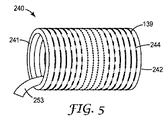
図5に例示される実施形態において、支持コア240は、第2端部242と反対の第1端部241を含む螺旋状に巻かれたリボン支持コアであり、端部242から端部241へと支持コア240を巻き戻すか又はほどくように構成されたタブ253を含む。本発明のこの実施形態において、接続部139の強度は、接続部の境界結合部の断面積(すなわち、図5の暗い領域)、及び接続部の間の間隔を一定に保つ一方で、接続部の長さを修正することによって、変化する。端部241及び242付近の接続部の長さは、端部241及び242の下方の接続部の長さ(これは、中間的長さの接続部の区分、及び短い長さの接続部の中間区分を含む)と比較して長い。この実施形態の接続部の強度は、正弦波、又は三角波を本質的に変化させる。タブ253が引かれ、支持コア240が端部242から端部241へと巻き戻されると、長い接続部の区分は、より強い結合強度を有し、分離により大きな力を必要とし、中間的長さの接続部は分離に必要な力がより少なくなり、中間区分の短い接続部は分離に必要な力が更に小さくなり、簡単に巻き戻される。他の好適な接続強度パターンとしては、長い接続部及び短い接続部の区分が交互となる方形波パターン、又は長い、中間的な、及び短い接続部の区分がこの順で反復される鋸歯状波が挙げられる。いくつかの実施形態において、図5の支持コア240の中央部のものなどの、より脆弱な結合部は、長い及び中間的接続部が巻き戻されると、支持コア240にかけられた伸張した常温収縮チューブ(図示されない)の力により圧潰するように設計されている。
In the embodiment illustrated in FIG. 5, the
別個の接続部の代わりに、連続的なシームを含むいくつかの実施形態において、シームの境界結合部の断面積は、シームの長さに沿って変化してもよい。上記のように、適用される接着剤の量を変える、又は溶接プロセスの態様を変えるなどの方法を使用して、所望のバリエーションを達成することができる。 In some embodiments including continuous seams instead of separate connections, the cross-sectional area of the seam boundary joint may vary along the length of the seam. As described above, methods such as changing the amount of adhesive applied or changing aspects of the welding process can be used to achieve the desired variation.
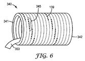
図6に例示されるように、他の実施形態において、チューブ340の周囲部の周辺により脆弱な接続部を含む残りの区分に挟まれた、強い接続部139の間欠的にずれている区分345であり得る。加えて、隣接する区分のずれの量は、より強い区分が互いに直接隣接するか、大きな若しくは小さな度合いで重複するか、又は全く重複しないように、変化させることもできる。いくつかの実施形態において、強い接続区分は、互いに等間隔であってもよく、他の実施形態において、間隔は間欠的であってもよい。本発明の少なくとも一実施形態において、リボンの一区分の周囲部の約1/10が強い接続部を含み、リボンの同じ区分の周囲部の約9/10が、弱い接続部を含むか、又は接続部を含まない。本発明の少なくとも一実施形態において、接続部の間でリボンが2周、3周又は4周以上している場合がある。これは、特定の支持コア及び用途における要求に応じて変化し得る。例えば、支持コアのフープ強度は典型的には、支持コアの直径の増加に伴って減少する。したがって、いくつかの実施形態において、より大きな直径の支持コアのために、強い接続部の面積がより大きいことが望ましい場合がある。支持コアを作製するための材料、加えて支持コアの構造、及び常温収縮チューブの圧縮力もまた、接続部の所望のパターン及び強度レベルに影響する。全体として、接続部139は、拡張状態の常温収縮を支持するために、最終的な支持コアに十分な強度をもたらす。
As illustrated in FIG. 6, in another embodiment, the intermittently displaced
本発明の実施形態において、リボン130は、上述の結合技術のために好適であり、スリーブの支持のために十分な強度を有する、いずれかのポリマー材料から作製され得る。好適な材料としては、熱可塑性材料、好ましくはポリオレフィンが挙げられるがこれらに限定されない。本発明の支持コアが、図2の先行技術の支持コアのものと同様の一般的構造を有する場合、リボン130の本体は、図2に示される支持部材50と同様の支持部材を備えることがある。支持部材は、リボン130の長さに沿って長手方向に延びることがある。支持部材は好ましくは、リボン130の残りの部分を形成する材料よりも、強い強度及び耐熱性を有し、よって、リボン130にこの支持部材を含めることによって、リボン130から形成される支持コアは、大きな直径の伸張した常温収縮チューブにより高い圧力に晒された際、及び高い温度条件で保存された際に、時期尚早の圧潰に対してより高い抵抗を示す。好ましくは、支持部材は、ABS樹脂(アクリロニトリル、ブタジエン、及びスチレン系のターポリマー)などの、熱可塑性材料であり、リボン130の残りの部分は、ポリオレフィン樹脂などの、熱可塑性材料から形成される。支持部材のための他の好適な材料としては、例えば、変性したPPO(ポリフェニレンオキサイド)樹脂が挙げられる。支持部材は好ましくは、リボン130の本体と共に共押出しされる。しかしながら、支持部材を備えるリボン130を形成する他の方法は、当業者に認識され得、本発明の領域において想到される。
In embodiments of the present invention, the
本明細書において特定の実施形態が例示及び説明されてきたが、本発明の範囲から逸脱することなく、多様な代替及び/又は同等の実施態様が特定の実施形態と置き換えられ得ることは、当業者には明白であろう。本願は、本明細書で論じた管状支持コアのいかなる改作又は変型をも包含することを意図したものである。したがって、本発明が請求項及びその同等物によってのみ限定されることを、意図するものである。 While specific embodiments have been illustrated and described herein, it is to be understood that various alternative and / or equivalent embodiments may be substituted for the specific embodiments without departing from the scope of the invention. It will be obvious to the contractor. This application is intended to cover any adaptations or variations of the tubular support core discussed herein. Therefore, it is intended that this invention be limited only by the claims and the equivalents thereof.
Claims (3)
前記1つ以上の結合部の強度が、前記管状支持コアの前記長さに沿って変化し、
前記結合強度が、前記管状支持コアの前記長さに沿って規則的な反復パターンで変化している、物品。 A spirally wound ribbon forming a tubular support core, the ribbon having a first edge and a second edge, wherein the adjacent first edge and second edge are the tubular support A ribbon comprising one or more joints along the length of the core;
Intensity of said one or more binding portion is changed along the length of the tubular support core,
The article , wherein the bond strength varies in a regular repeating pattern along the length of the tubular support core .
前記管状支持コアを形成する螺旋状に巻かれたリボンであって、前記リボンは第1縁部及び第2縁部を有し、隣接する第1縁部及び第2縁部は、前記管状支持コアの前記長さに沿って1つ以上の結合部を含む、リボンと、を有し、
前記1つ以上の結合部の強度が、前記管状支持コアの前記長さに沿って変化し、
前記結合強度が、前記管状支持コアの前記長さに沿って規則的な反復パターンで変化している、物品。 An elastomer sleeve supported in a greatly stretched state over the length of the hollow tubular support core;
A spirally wound ribbon forming the tubular support core, the ribbon having a first edge and a second edge, wherein the adjacent first edge and second edge are the tubular support A ribbon that includes one or more joints along the length of the core;
The strength of the one or more binding portion is changed along the length of the tubular support core,
The article , wherein the bond strength varies in a regular repeating pattern along the length of the tubular support core .
Applications Claiming Priority (3)
| Application Number | Priority Date | Filing Date | Title |
|---|---|---|---|
| US201161579315P | 2011-12-22 | 2011-12-22 | |
| US61/579,315 | 2011-12-22 | ||
| PCT/US2012/070303 WO2013096287A2 (en) | 2011-12-22 | 2012-12-18 | Support core for cold shrink tube |
Publications (3)
| Publication Number | Publication Date |
|---|---|
| JP2015503892A JP2015503892A (en) | 2015-02-02 |
| JP2015503892A5 JP2015503892A5 (en) | 2016-02-04 |
| JP6117237B2 true JP6117237B2 (en) | 2017-04-19 |
Family
ID=47604089
Family Applications (1)
| Application Number | Title | Priority Date | Filing Date |
|---|---|---|---|
| JP2014549198A Active JP6117237B2 (en) | 2011-12-22 | 2012-12-18 | Support core for cold shrink tube |
Country Status (9)
| Country | Link |
|---|---|
| US (1) | US8709557B2 (en) |
| EP (1) | EP2795754B1 (en) |
| JP (1) | JP6117237B2 (en) |
| CN (1) | CN104040814B (en) |
| BR (1) | BR112014014961B1 (en) |
| ES (1) | ES2675243T3 (en) |
| MX (1) | MX2014007432A (en) |
| TW (1) | TWI537987B (en) |
| WO (1) | WO2013096287A2 (en) |
Families Citing this family (6)
| Publication number | Priority date | Publication date | Assignee | Title |
|---|---|---|---|---|
| JP6128996B2 (en) * | 2013-06-28 | 2017-05-17 | スリーエム イノベイティブ プロパティズ カンパニー | String and covering treatment tool |
| CN103594959A (en) * | 2013-12-05 | 2014-02-19 | 深圳市沃尔核材股份有限公司 | Supporting bar suitable for cold compression process |
| US10148077B2 (en) * | 2014-04-08 | 2018-12-04 | Te Connectivity Corporation | Sealing systems and methods for elongate members |
| WO2020101968A1 (en) | 2018-11-16 | 2020-05-22 | Corning Incorporated | Cordierite-containing ceramic bodies, batch composition mixtures, and methods of manufacturing cordierite-containing ceramic bodies |
| JP2022527583A (en) | 2019-04-09 | 2022-06-02 | スリーエム イノベイティブ プロパティズ カンパニー | Support core for elastic sleeve |
| CN110001096A (en) * | 2019-04-18 | 2019-07-12 | 山东华凌电缆有限公司 | A kind of preparation method of cold shrink tube |
Family Cites Families (18)
| Publication number | Priority date | Publication date | Assignee | Title |
|---|---|---|---|---|
| US3562079A (en) * | 1967-10-27 | 1971-02-09 | Uniroyal Inc | Coiled-filament non-woven fabrics |
| US3515798A (en) * | 1968-12-06 | 1970-06-02 | Minnesota Mining & Mfg | Elastic cover and removable cone assembly |
| AU6219890A (en) | 1989-10-16 | 1991-04-18 | Minnesota Mining And Manufacturing Company | Elastomeric covering having conformable interior |
| JP2697392B2 (en) | 1991-07-30 | 1998-01-14 | ソニー株式会社 | Method of manufacturing complementary semiconductor device |
| IT1252219B (en) * | 1991-12-16 | 1995-06-05 | Pirelli Cavi Spa | COVERING COMPLEX OF ELONGATED CYLINDRICAL ELEMENTS SUCH AS ELECTRIC CABLE JOINTS. |
| US5925427A (en) | 1995-02-06 | 1999-07-20 | Minnesota Mining And Manufacturing Company | Support core ribbon for cold-shrink tube |
| US5670223A (en) | 1995-02-06 | 1997-09-23 | Minnesota Mining And Manufacturing Company | Support core ribbon for cold-shrink tube |
| US5670233A (en) * | 1995-06-29 | 1997-09-23 | The United States Of America As Represented By The Secretary Of The Navy | Acoustic window and method for making the same |
| JP2000102156A (en) * | 1998-09-21 | 2000-04-07 | Fujikura Ltd | Diameter expansion retention spacer for tube shrinking at normal-temperature |
| US6138439A (en) * | 1999-05-21 | 2000-10-31 | Illinois Tool Works Inc. | Methods of making slide-zippered reclosable packages on horizontal form-fill-seal machines |
| JP4690559B2 (en) * | 2000-02-17 | 2011-06-01 | 古河電気工業株式会社 | Insulated cylinder with expanded support cylinder |
| US20050069657A1 (en) * | 2001-11-28 | 2005-03-31 | Shigeru Suzuki | Tearable core member and cold-shrink tube device having the same |
| JP3946035B2 (en) * | 2001-11-28 | 2007-07-18 | スリーエム イノベイティブ プロパティズ カンパニー | Tearable core member and cold shrink tube device having the core member |
| ATE442878T1 (en) * | 2002-09-03 | 2009-10-15 | Clean Cut Technologies Llc | DEVICE FOR PACKAGING LONG-LONG SURGICAL DEVICES |
| US6838959B2 (en) * | 2003-04-14 | 2005-01-04 | Agilent Technologies, Inc. | Longitudinal electromagnetic latching relay |
| US7744977B2 (en) * | 2006-05-24 | 2010-06-29 | Tyco Electronics Raychem Gmbh | Support coil comprising a mechanical locking means and method for the production thereof |
| US20090056101A1 (en) * | 2007-08-29 | 2009-03-05 | Standard Aero Limited | Method for securing a threaded insert in a threaded opening |
| DE102008023963A1 (en) * | 2008-05-16 | 2009-12-10 | Tyco Electronics Raychem Gmbh | Laser beam absorbing support helix and method and apparatus for making the same |
-
2012
- 2012-12-18 US US13/718,201 patent/US8709557B2/en active Active
- 2012-12-18 ES ES12818718.4T patent/ES2675243T3/en active Active
- 2012-12-18 WO PCT/US2012/070303 patent/WO2013096287A2/en active Application Filing
- 2012-12-18 EP EP12818718.4A patent/EP2795754B1/en active Active
- 2012-12-18 MX MX2014007432A patent/MX2014007432A/en active IP Right Grant
- 2012-12-18 JP JP2014549198A patent/JP6117237B2/en active Active
- 2012-12-18 CN CN201280063688.7A patent/CN104040814B/en active Active
- 2012-12-18 BR BR112014014961-5A patent/BR112014014961B1/en active IP Right Grant
- 2012-12-21 TW TW101149154A patent/TWI537987B/en not_active IP Right Cessation
Also Published As
| Publication number | Publication date |
|---|---|
| CN104040814B (en) | 2017-07-11 |
| TW201342395A (en) | 2013-10-16 |
| EP2795754B1 (en) | 2018-04-11 |
| US8709557B2 (en) | 2014-04-29 |
| JP2015503892A (en) | 2015-02-02 |
| US20130164475A1 (en) | 2013-06-27 |
| BR112014014961A2 (en) | 2017-06-13 |
| WO2013096287A3 (en) | 2014-01-03 |
| EP2795754A2 (en) | 2014-10-29 |
| WO2013096287A2 (en) | 2013-06-27 |
| BR112014014961B1 (en) | 2021-01-26 |
| TWI537987B (en) | 2016-06-11 |
| ES2675243T3 (en) | 2018-07-09 |
| MX2014007432A (en) | 2014-07-28 |
| CN104040814A (en) | 2014-09-10 |
Similar Documents
| Publication | Publication Date | Title |
|---|---|---|
| JP6117237B2 (en) | Support core for cold shrink tube | |
| US5925427A (en) | Support core ribbon for cold-shrink tube | |
| CA2211178C (en) | Support core ribbon for cold-shrink tube | |
| US5844170A (en) | Closure with flowable material and reinforcing core | |
| EP2800921B1 (en) | Heat-shrinkable tube covering | |
| EP0117092A1 (en) | Plastic core for an elastically shrinkable tubular cover | |
| JP2014097390A5 (en) | ||
| JPH0928015A (en) | Supporting body for elastic body and manufacture thereof | |
| CN110192137B (en) | Two-piece armored optical cable | |
| KR102275463B1 (en) | Spiral wrapped nonwoven sleeve and method of construction thereof | |
| PT1835591E (en) | Helical support and method for the production thereof | |
| EP3289271B1 (en) | Joining method | |
| EP2317203A1 (en) | Method for coating a joint between two pipes | |
| US8192816B2 (en) | Support coil with mechanical locking device and method for its manufacture | |
| JPH0835587A (en) | Resin pipe | |
| EP0778929A1 (en) | Reinforced, variable-sized coupling for conduit | |
| JP2000102156A (en) | Diameter expansion retention spacer for tube shrinking at normal-temperature | |
| JP3938406B2 (en) | Closure with flowable material and reinforcing core | |
| KR200347803Y1 (en) | pipe coupler | |
| KR20050047011A (en) | Pipe coupler | |
| JP2005088253A (en) | Inner core for normal temperature shrinkable tube and manufacturing method of inner core | |
| JPWO2004101416A1 (en) | Method for manufacturing a roll of thermoplastic resin string | |
| DE102012109796A1 (en) | Detection assistance for detecting plastic pipes laid on ground, has plastic strip extended longitudinally to pipe, and metallic detection wire embedded into plastic tape or connected between plastic tapes along longitudinal direction | |
| JPH11173484A (en) | Electro-fusion joint |
Legal Events
| Date | Code | Title | Description |
|---|---|---|---|
| A521 | Request for written amendment filed |
Free format text: JAPANESE INTERMEDIATE CODE: A523 Effective date: 20151211 |
|
| A621 | Written request for application examination |
Free format text: JAPANESE INTERMEDIATE CODE: A621 Effective date: 20151211 |
|
| A977 | Report on retrieval |
Free format text: JAPANESE INTERMEDIATE CODE: A971007 Effective date: 20161109 |
|
| A131 | Notification of reasons for refusal |
Free format text: JAPANESE INTERMEDIATE CODE: A131 Effective date: 20161122 |
|
| A601 | Written request for extension of time |
Free format text: JAPANESE INTERMEDIATE CODE: A601 Effective date: 20170222 |
|
| A521 | Request for written amendment filed |
Free format text: JAPANESE INTERMEDIATE CODE: A523 Effective date: 20170224 |
|
| TRDD | Decision of grant or rejection written | ||
| A01 | Written decision to grant a patent or to grant a registration (utility model) |
Free format text: JAPANESE INTERMEDIATE CODE: A01 Effective date: 20170307 |
|
| A61 | First payment of annual fees (during grant procedure) |
Free format text: JAPANESE INTERMEDIATE CODE: A61 Effective date: 20170322 |
|
| R150 | Certificate of patent or registration of utility model |
Ref document number: 6117237 Country of ref document: JP Free format text: JAPANESE INTERMEDIATE CODE: R150 |