JP6107422B2 - Heat exchange unit and local body cleaning device - Google Patents
Heat exchange unit and local body cleaning device Download PDFInfo
- Publication number
- JP6107422B2 JP6107422B2 JP2013110844A JP2013110844A JP6107422B2 JP 6107422 B2 JP6107422 B2 JP 6107422B2 JP 2013110844 A JP2013110844 A JP 2013110844A JP 2013110844 A JP2013110844 A JP 2013110844A JP 6107422 B2 JP6107422 B2 JP 6107422B2
- Authority
- JP
- Japan
- Prior art keywords
- transfer plate
- heat transfer
- heat
- fluid container
- exchange unit
- Prior art date
- Legal status (The legal status is an assumption and is not a legal conclusion. Google has not performed a legal analysis and makes no representation as to the accuracy of the status listed.)
- Active
Links
Images


Description
本発明は、熱交換ユニットおよび人体局部洗浄装置に関し、さらに詳しくは、流体を加熱する熱交換ユニットおよびそのような熱交換ユニットを備える人体局部洗浄装置に関する。 The present invention relates to a heat exchange unit and a human body local cleaning device, and more particularly to a heat exchange unit that heats a fluid and a human body local cleaning device including such a heat exchange unit.
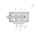
人体局部洗浄装置等に備えられ、所定の温度に加熱された温水を供給する熱交換ユニットにおいて、水の流路に金属等熱伝導率の高い材料よりなる伝熱板(感熱板、放熱板)を設け、トライアック等の発熱する電子部品や、温度ヒューズ等の安全装置を、その伝熱板上に設ける構成が公知である。この場合、図5に模式的に示すように、従来の熱交換ユニット90においては、ヒータ92を収容し、流体の流路Cを構成する流体容器91の側壁面91aに伝熱板93が設けられている。例えば、特許文献1においては、流体容器(円筒躯体72a)の側壁面に開口(バイメタル取付用開口72e)を形成し、伝熱板(73a)を備えるバイメタルスイッチ73が取り付けられている。また、特許文献2においても、流体容器(給湯タンク3)の側壁に、トライアックが取り付けられた構成が示されている(特許文献2中図1参照)。
A heat exchange unit (heat sensitive plate, heat radiating plate) made of a material having high thermal conductivity, such as metal, in a water flow path in a heat exchange unit that is provided in a human body local cleaning device and supplies hot water heated to a predetermined temperature. There is a known configuration in which a heat generating electronic component such as a triac and a safety device such as a thermal fuse are provided on the heat transfer plate. In this case, as schematically shown in FIG. 5, in the conventional
上記のように、トライアックやヒューズ等の電子部品を設置するための伝熱板を、流路を構成する流体容器の側壁の中途部位に設ける場合には、図5に示すように、樹脂等よりなる流体容器91の側壁面91aに開口部95を形成し、この開口部95を金属等よりなる伝熱板93によって閉塞することになる。すると、流路Cの壁面には、伝熱板93と隣接する部位との間に、不可避的に段差Sが生じ、伝熱板93が配置された部位において、他の部位に比べて流路の断面積Cが不均一に広くなってしまう。すると、流路Cを流れる流体が空間的に均一に加熱を受けにくくなり、加熱のムラが生じてしまう。
As described above, when a heat transfer plate for installing electronic components such as a triac and a fuse is provided in the middle of the side wall of the fluid container constituting the flow path, as shown in FIG. An
本発明が解決しようとする課題は、流体の流路の途中に伝熱板が設けられ、伝熱板上に電子部品が設けられた熱交換ユニットにおいて、流路中の流体の均一な流れが安定に維持される熱交換ユニットを提供すること、そしてそのような熱交換ユニットを有する人体局部洗浄装置を提供することにある。 A problem to be solved by the present invention is that in a heat exchange unit in which a heat transfer plate is provided in the middle of a fluid flow path, and an electronic component is provided on the heat transfer plate, a uniform flow of fluid in the flow path is achieved. It is to provide a heat exchange unit that is stably maintained, and to provide a human body local washing device having such a heat exchange unit.
上記課題を解決するために、本発明にかかる熱交換ユニットは、流体が流れる流路を内部に有し、両端面に開口を有する筒状の流体容器と、前記流体容器の内部に設けられ、前記流路を流れる流体を加熱する加熱手段と、を備え、前記流体容器の開口のうち一方は、前記加熱手段および前記加熱手段と一体に形成されたフランジ部によって閉塞され、他方は、前記流体と接触し、前記流体容器の内側に臨む面と外側に臨む面との間で熱を伝達する伝熱板によって閉塞され、前記伝熱板の前記流体容器の外側に臨む面には、発熱する電子部品および熱を検知して作動する電子部品の少なくとも一方が配置されていることを要旨とする。 In order to solve the above problems, a heat exchange unit according to the present invention has a flow path through which a fluid flows, a cylindrical fluid container having openings on both end faces, and a fluid container provided inside the fluid container. Heating means for heating the fluid flowing through the flow path, one of the openings of the fluid container being closed by the heating means and a flange portion formed integrally with the heating means, and the other being the fluid The heat transfer plate is closed by a heat transfer plate that transfers heat between the surface facing the inside and the surface facing the outside of the fluid container, and heat is generated on the surface of the heat transfer plate facing the outside of the fluid container. The gist is that at least one of an electronic component and an electronic component that operates by detecting heat is disposed.
ここで、前記加熱手段は中空の筒状であり、その先端部と前記伝熱板の間には流体が通過可能な空間が形成され、前記流路は、前記加熱手段の中空部から前記空間を通り、前記加熱手段の外壁と前記流体容器の内壁の間に形成された空間に至るものであることが好適である。 Here, the heating means has a hollow cylindrical shape, and a space through which a fluid can pass is formed between a tip portion of the heating means and the heat transfer plate, and the flow path passes through the space from the hollow portion of the heating means. It is preferable that it reaches a space formed between the outer wall of the heating means and the inner wall of the fluid container.
さらに、前記伝熱板は、前記流体容器の外壁よりも外側まで延出していることが好ましい。 Furthermore, it is preferable that the heat transfer plate extends to the outside of the outer wall of the fluid container.
本発明にかかる人体局部洗浄装置は、上記のような熱交換ユニットによって加熱された温水を人体局部洗浄用に供給することを要旨とする。 The gist of a human body local cleaning device according to the present invention is to supply hot water heated by the heat exchange unit as described above for human body local cleaning.
上記本発明にかかる熱交換ユニットにおいては、発熱する電子部品および/または熱を検知して作動する電子部品が伝熱板を介して流路を流れる流体と熱的に接触しているため、発熱する電子部品を流路を流れる流体によって冷却することができる。また熱を検知して作動する電子部品を流路を流れる流体の熱によって作動させることができる。伝熱板が、筒状の流体容器の側壁の一部として構成されているのではなく、流体容器の一方の開口全体を閉塞して構成されているので、伝熱板の存在が、流路の断面積に影響を与えず、流路中における流体の均一な流れが維持される。これにより、流体が高い均一性を有して加熱手段によって加熱される。 In the heat exchange unit according to the present invention, the electronic component that generates heat and / or the electronic component that operates by detecting heat is in thermal contact with the fluid flowing through the flow path via the heat transfer plate. The electronic component to be cooled can be cooled by the fluid flowing through the flow path. In addition, an electronic component that operates by detecting heat can be operated by the heat of the fluid flowing through the flow path. The heat transfer plate is not configured as a part of the side wall of the cylindrical fluid container, but is configured by closing the entire opening of one of the fluid containers. The cross-sectional area of the fluid is not affected, and the uniform flow of the fluid in the flow path is maintained. As a result, the fluid is heated by the heating means with high uniformity.
加えて、伝熱板が、熱伝達の役割だけでなく、流路の開口の一方を閉塞するための部材としての役割を果たすことから、流路の開口を閉塞するための部材と別に伝熱板を設ける場合と比較して、部品点数を削減し、熱交換ユニットの製造コストを削減することができる。 In addition, the heat transfer plate not only plays a role of heat transfer but also serves as a member for closing one of the openings of the flow path, so that heat transfer is performed separately from the member for closing the opening of the flow path. Compared with the case where a board is provided, the number of parts can be reduced, and the manufacturing cost of the heat exchange unit can be reduced.
ここで、加熱手段が中空の筒状であり、その先端部と伝熱板の間に流体が通過可能な空間が形成され、流路が、加熱手段の中空部からその空間を通り、加熱手段の外壁と流体容器の内壁の間に形成された空間に至るものである場合には、流路が単純な形状、つまり、略均一な断面積の直線的な部分が結合された折れ線状の単純な形状を有する。このように、流路の形状そのものの効果として、流路に沿った流体の流れの均一性が高いため、その高い均一性が伝熱板の存在によって乱されないことの効果が一層大きく享受される。また、流路を流れる流体が伝熱板に当たって折り返すうえ、流体が伝熱板に接触する部位が流路のほぼ中間点に位置し、伝熱板に接触する流体があまり高温まで加熱されていないので、伝熱板の外側に設置された発熱する電子部品に対する冷却効果が高くなる。 Here, the heating means has a hollow cylindrical shape, a space through which fluid can pass is formed between the tip portion and the heat transfer plate, and the flow path passes through the space from the hollow portion of the heating means, and the outer wall of the heating means And the inner wall of the fluid container, the flow path has a simple shape, that is, a simple polygonal shape in which straight portions with a substantially uniform cross-sectional area are joined. Have As described above, as the effect of the shape of the flow path itself, since the uniformity of the fluid flow along the flow path is high, the effect that the high uniformity is not disturbed by the presence of the heat transfer plate is further enjoyed. . In addition, the fluid flowing through the flow path hits the heat transfer plate and turns back, and the portion where the fluid contacts the heat transfer plate is located at an approximately middle point of the flow path, and the fluid contacting the heat transfer plate is not heated to a very high temperature. Therefore, the cooling effect with respect to the heat-generating electronic component installed outside the heat transfer plate is enhanced.
さらに、伝熱板が、流体容器の外壁よりも外側まで延出している場合には、電子部品を配置することができる領域の面積が大きくなり、複数の電子部品を配置することが容易となる。また、電子部品の発熱が相互の動作に影響を与えないように、電子部品同士を離して配置することも容易となる。 Furthermore, when the heat transfer plate extends to the outside of the outer wall of the fluid container, the area of the area where the electronic component can be arranged becomes large, and it becomes easy to arrange a plurality of electronic components. . In addition, it is easy to place the electronic components apart so that the heat generated by the electronic components does not affect the mutual operation.
本発明にかかる人体局部洗浄装置によると、熱交換ユニットにおいて、電子部品が配置される伝熱板によって流路中における流体の均一な流れが妨げられず、流体の流れが安定に維持され、流体が均一に加熱されるので、使用者が快適に人体局部洗浄装置を使用することができる。 According to the human body local cleaning device according to the present invention, in the heat exchange unit, the uniform flow of the fluid in the flow path is not hindered by the heat transfer plate on which the electronic components are arranged, and the fluid flow is stably maintained. Is heated uniformly, so that the user can comfortably use the local body cleaning device.
以下、本発明の実施形態にかかる熱交換ユニットついて図面を参照しつつ詳細に説明する。 Hereinafter, a heat exchange unit according to an embodiment of the present invention will be described in detail with reference to the drawings.
(第一の実施形態)
図1および図2は、本発明の第一の実施形態にかかる熱交換ユニット1の断面を示している。熱交換ユニットは、熱交換器や流体加熱装置とも称され、内部に流入された流体を所定温度に加熱し、外部に供給するものである。以下では、熱交換ユニットによって加熱される流体を水として説明を行う。
(First embodiment)
1 and 2 show a cross section of the heat exchange unit 1 according to the first embodiment of the present invention. The heat exchange unit is also referred to as a heat exchanger or a fluid heating device, and heats the fluid flowing into the inside to a predetermined temperature and supplies the fluid to the outside. Hereinafter, the fluid heated by the heat exchange unit will be described as water.
本実施形態にかかる熱交換ユニット1においては、通電により水を加熱できるヒータ12が流体容器10の中に挿入されている。流体容器10は、公共水道等の水源から水が流入する流入口13と温水が流出する流出口14とを備え、水源から供給された低温の水をヒータ12により加熱し、連続的に温水を流出口14から外部に供給することができる。流体容器10の底部には、伝熱板20が設けられ、伝熱板20には、熱交換ユニット1の制御に使用される電子部品30が設けられている。以下、各部材の構成と配置について、詳細に説明する。なお、説明は省略するが、熱交換ユニット1は、上記各部材に加え、加熱された温水の温度を検出する温度センサや、水の流入および/または流出を調節するバルブ、水流計、各種安全装置等を適宜備えることができる。
In the heat exchange unit 1 according to the present embodiment, a
ヒータ12は電力により水を加熱することができる絶縁性の高いヒータである。熱交換ユニット1全体を小さく設計することや、後述するように水が流路の中途部位に設けられた伝熱板に当たって循環する流路を構成することを考えると、ヒータ12としては、内壁面12a及び外壁面12bの両方で加熱可能な中空円筒形の加熱部12cを有するセラミックヒータを使用することが好適である。ヒータ12においては、加熱部12cと一体に、フランジ部12dが形成されている。ヒータ12の出力は、電流入力を制御することによって行われる。このヒータ12への電流入力の制御は、トライアックによって行われる。また、ヒータ12による異常加熱を防止するため、ヒータ12への電流入力を行う回路には、適宜温度ヒューズが設けられている。
The
流体容器10はヒータ12を内部に収容しており、流体容器10の側壁面11およびヒータ12によって区画された空間に水が流通する流路Cが形成されている。流体容器10は、両端に開口10a,10bを有する略筒形の形状を有する。上部開口10aからは、加熱部12cの中心軸が流体容器10の長手方向軸に平行になるように、ヒータ12が挿入され、ヒータ12の加熱部12cおよびフランジ部12dによって上部開口10aが閉塞されている。流体容器10の底部開口10bは、伝熱板20によって閉塞されている。伝熱板20は、銅に代表される金属のような高い熱伝導率を有する板材よりなり、シール部材25を介して流体容器10の開口部に取り付けられている。加熱部12cの先端部と、伝熱板20の間には、流体が通過するための空間が設けられている。本実施形態においては、伝熱板20は、流体容器10の底部開口10bの外縁を構成する側壁面11の外周と略同形状の外形を有している。
The
つまり、ヒータ12上端の開口部として設けられた流入口13から入った水は、加熱部12cの円筒体内を加熱部12cの軸方向に流れ、加熱部12cの先端部に至る。水は次に加熱部12cの先端部と伝熱板20の間の空間に移動する。さらに、水は、伝熱板20の部位から流体容器10の上部に設けられた流出口14に向かって、流体容器10の長手方向沿って流れる。水はこの流路Cを流れる間に、加熱部12cの内壁面12aおよび外壁面12bとの接触によって加熱される。
That is, water that has entered from the
流体容器10の底部開口10bを閉塞している伝熱板20の外側面20bには、動作時に発熱する発熱電子部品30が密着して取り付けられている。伝熱板20は、高い熱伝導率を有しており、伝熱板20の内側面20aと外側面20bの間に高効率で熱伝達が起こる。つまり、伝熱板20の内側面20aと接触する水と、外側面20bに接する発熱電子部品30とが熱的に接触され、発熱電子部品30が、流路Cを流れる水によって冷却される。
A heat generating
発熱電子部品30としては、ヒータ12への電流入力を制御するトライアックを挙げることができる。トライアックは動作時に非常に高温まで発熱する電子部品であり、容易に100℃以上にまで加熱される。よって、流路Cを流れる水はヒータ12によって加熱されているものの、通常はトライアックよりも低温であり、流路Cを流れる水を使用してトライアックの冷却を行うことができる。特に、熱交換ユニット1が人体局部洗浄装置に使用される場合には、熱交換ユニット1が供給する温水温度の上限は、人体に接触しても過度に熱く感じられない温度(例えば40℃程度)であるので、流路Cを流れる水の温度はトライアックの発熱温度に比べてはるかに低く、トライアックを効率的に冷却することができる。
An example of the heat generating
また、発熱電子部品30とともに、あるいは発熱電子部品30のかわりに、熱を検知して作動する感熱電子部品が伝熱板20上に設けられてもよい。伝熱板20を介して感熱電子部品と流路Cを流れる水の間で熱交換が行われることにより、流路Cを流れる水の温度によって、感熱電子部品が作動される。感熱電子部品としては、ヒータ12への電流入力回路の途中に設けられる温度ヒューズ、バイメタルスイッチ等の安全装置を挙げることができる。つまり、流路Cを流れる水が異常加熱されると、その熱が温度ヒューズやバイメタルスイッチに伝達され、所定の閾値温度を超えた時に、ヒータ12への電流入力が遮断され、異常加熱状態が強制的に解消される。
A heat sensitive electronic component that operates by detecting heat may be provided on the
このように、筒状の流体容器10の底部開口10bが伝熱板20によって閉塞され、その内側面20aが流路Cを流れる水に直接接触し、その外側面20bに発熱電子部品および/または感熱電子部品が取り付けられることで、流路Cを流れる水を用いて発熱電子部品を冷却することができる。また、異常加熱等への対策を感熱電子部品を用いて行うことができる。ここで、伝熱板20が、図5に示した場合のように流体容器10の側壁部の一部として形成されているのではなく、底部開口10b全体を閉塞する部材として形成されていることで、伝熱板20が流路Cの形状に影響を与えない。つまり、伝熱板20が存在することで、流路Cを構成する壁面に、流路Cの断面形状や断面積に影響を与えるような段差構造が形成されることがなく、流路Cの壁面が平滑な状態に維持される。これにより、伝熱板20の存在が流路Cを流れる水の加熱の均一性に影響を与えることが防止されている。もし伝熱板20が設けられた部位において、局所的に流路Cの断面積や断面形状が変調を受けると、ヒータ12によって水を空間的に均一に加熱することが困難になり、水の加熱に空間的なムラが生じる。その結果、熱交換ユニットから供給される温水の温度が一定しなくなり、使用者に不快感を与えることになる。しかし、本実施形態にかかる熱交換ユニット1においては、伝熱板20の存在によって流路Cの断面積が影響を受けないので、このような流路Cの形状に起因する水流の不均一性と加熱のムラを排除することができ、供給される温水の温度の一定性を高めることができる。
As described above, the
特に本実施形態にかかる熱交換ユニット1では、流路C全体における断面積および断面形状の変化が小さいので、伝熱板20が流路Cの断面積および断面形状に影響を与えないことによる、加熱の均一性維持の効果が大きく享受される。つまり、本実施形態にかかる熱交換ユニット1では、筒状の流体容器10にヒータ12の中空円筒状の加熱部12cが挿入されており、流路Cが、ヒータ12の加熱部12cの中空部から流体容器10の底部を通り、折り返してヒータ外壁面10bと流体容器10の側壁面11の間の空間に至る、略折れ線状の単純な形状よりなっており、その途中に、伝熱板20を含めて、水流を妨げるような突出部や凹部を有していない。これにより、均一性の高い水流が安定に得られ、加熱される。
In particular, in the heat exchange unit 1 according to the present embodiment, the change in the cross-sectional area and the cross-sectional shape of the entire flow path C is small, so that the
また、流体容器10の底部に伝熱板20が設けられていることで、ヒータ12の中空部から流れ出た水が伝熱板20に当たって折り返す。つまり、伝熱板20の内側面20aは、流体の流束に略垂直に交差しており、伝熱板20の内側面20aは、略垂直の方向から、循環する水の流れを常に受けている(図2参照)。これによって、流路C中の水の温度が伝熱板20に高効率で伝達され、伝熱板20の外側面20bに設けられる電子部品30が発熱電子部品である場合には、その冷却が効果的に行われることになる。伝熱板20の外側面20bに設けられる電子部品が感熱電子部品である場合には、流体の温度変化に敏感に反応してその感熱電子部品が作動するようになる。さらに、本実施形態においては、ヒータ12の中空円筒状の加熱部12cの内壁面12aと外壁面12bの両方に接触した水が加熱されるので、水が加熱を受ける流路Cのほぼ中間に伝熱板20が設けられていることになる。これにより、伝熱板20の内側面20aに接触する水は、流出口14の部位における目標温度までには加熱されておらず、加熱部12cの外壁面12bと流体容器10の側壁面11との間を流れる水よりも低温の状態にある。よって、伝熱板20の外側面20bに設けられる電子部品が発熱部品である場合に、伝熱板20が流体容器10の側壁部に設けられる場合よりも、高い冷却効率を得ることができる。
Further, since the
なお、本実施形態の場合のように、ヒータ12が円筒形の加熱部12cを有するものであることは必須ではなく、流体容器10中に構成される流路Cも、上記のように中空の加熱部12cの内側領域を通って、折り返して外側領域に至るようなものでなくてもよい。任意の形状のヒータ12および流路Cを有する熱交換ユニット1において、筒状の流体容器10の開口の一方を伝熱板20によって閉塞し、その伝熱板20の上に発熱電子部品および/または感熱電子部品を設ければ、水流の安定性を維持しながらそれら電子部品と流体容器10中の水との間の熱伝達を実現することができる。しかしながら、本実施形態のように、中空筒状の加熱部12cを有するヒータ12を用い、筒状の流体容器10の開口の一方をヒータ12のフランジ部12dで閉塞し、他方を伝熱板20で閉塞する構成とし、水がヒータ12の内側領域を通って、伝熱板20に当たって折り返して外側領域に至るような流路Cを形成しておくことによって、伝熱板20が存在していても安定性の高い水流を得られるという効果を大きく享受することができる。もし流路を構成する壁面に凹凸が形成されているなど、複雑な形状の流路の開口を閉塞して上記のような平板状の伝熱板が設けられる場合には、伝熱板の有無によらず、流路の形状自体に起因して、水流の均一性が低い状態にあるので、伝熱板の存在が水流の均一性を乱さないことの効果が限定的なものとなってしまう。また、上記のように、流路C中の水の温度が伝熱板20に高効率で伝達されるという効果や、伝熱板20に接触する水が比較的低温の状態にあって高い冷却効率が得られるという効果も、上記実施形態のように、水流が伝熱板20に当たって折り返す構成によって得られるものである。これらの点において、筒状の流体容器10の開口の一方を伝熱板20で閉塞してその外側面20bに電子部品30を配置するという構成を、中空筒状のヒータ12の内側部領域から外側領域に折り返す流路Cの形態と組み合わせる本実施形態にかかる熱交換ユニット1の構成が好適である。
In addition, it is not essential that the
さらに、本実施形態においては、伝熱板20が、その外側面20bに設けられた電子部品と流路Cを流れる水とを熱的に接触させる役割だけでなく、流体容器10の底部開口10bを物理的に閉塞する役割も果たす。つまり、流体容器10の底部開口10bを閉塞するための部材と伝熱板20とを独立した部材として設ける必要がない。よって、流体容器10の側壁面11に伝熱板20を設ける場合には、伝熱板20と底部開口10bを閉塞するための部材がそれぞれ必要となるのと比較して、熱交換ユニット1の製造コストを抑制することができる。
Furthermore, in the present embodiment, the
伝熱板20の外側面20bに設けられた電子部品と流路Cを流れる水との間の熱伝達の効率を高くするためには、電子部品は、伝熱板20の中央部、つまり流体容器10の底部開口10bの中央部に設けることが好ましい。また、電子部品の大きさと伝熱板20の面積の関係によって可能ならば、伝熱板20上に複数の電子部品を設置してもよい。この場合、各電子部品を伝熱板20のどの位置に配置するかは、各電子部品の形状や機能を勘案して適宜定めればよい。例えば、流路Cを流れる水との間の高効率な熱伝達がより高度に求められる電子部品を、伝熱板20の中央により近い位置に配置すればよい。また、特に発熱電子部品と感熱電子部品の両方を伝熱板20上に配置する場合には、発熱電子部品の発する熱が感熱電子部品の動作に影響を与えないように、両者を離して配置することが望ましい。
In order to increase the efficiency of heat transfer between the electronic component provided on the
(第二の実施形態)
上記第一の実施形態にかかる熱交換ユニット1においては、伝熱板20は、流体容器10の底部開口10bの外縁を構成する側壁面11の外周と略同形状の外形を有していたが、伝熱板の面積をそれよりも大きくし、流体容器10の側壁面11の位置よりも外側まで延びた延出部を設ける構成とすることができる。図3に示した第二の実施形態にかかる熱交換ユニット2は、このような延出部41を有している。第二の実施形態にかかる熱交換ユニット2においては、伝熱板40の延出部41が、曲折部42において折り曲げられ、曲折部42よりも外側が流体容器10の側壁面11と略平行とされている。
(Second embodiment)
In the heat exchange unit 1 according to the first embodiment, the
この熱交換ユニット2におけるように、伝熱板40が流体容器10の側壁面11よりも外側に延出して、大面積で設けられていることにより、伝熱板40上に複数の電子部品を設けることが容易となる。例えば、図示した第二の実施形態にかかる熱交換ユニット2においては、伝熱板40上に3つの電子部品30a〜30cが配置されている。また、伝熱板40が大面積であることにより、複数の電子部品の相互配置の自由度が高められ、それらを相互に離間させて設けることも容易となる。上記第一の実施形態にかかる熱交換ユニット1の場合と同様に、複数の電子部品のそれぞれの配置は、各電子部品の形状や機能に応じて適宜定めればよい。発熱電子部品と感熱電子部品の両方を伝熱板40上に設ける場合には、それらをできる限り相互に離間させることが望ましい。
As in the
なお、延出部41は、図3に示したように、流体容器10の一方向(図3中ではの下方)にのみ設けても、変形例として、二方向に設けてもよい。二方向に設ける場合、2つの延出部41を流体容器10を挟んで対向する位置に設ければよい。例えば、図3において、流体容器10の下方に設けられている延出部41に加えて、流体容器10の上方にも、折れ曲がり構造を有する同様の延出部41を形成すればよい。いずれの形態を採用するかは、伝熱板40上に配置する電子部品の数等を考慮して、適宜選択すればよい。
In addition, as shown in FIG. 3, the
このように、伝熱板40に折れ曲がり構造を有する延出部41が形成された第二の実施形態にかかる熱交換ユニット2の形式を採用すれば、次に述べるような、延出部を含む伝熱板全体が平板状に形成された第三の実施形態にかかる熱交換ユニットを採用する場合に比べ、流体容器10の長手方向と直交する方向について熱交換ユニット全体をコンパクトに形成することができる。
Thus, if the form of the
(第三の実施形態)
上記第二の実施形態にかかる熱交換ユニット2においては、伝熱板40の延出部は、曲折部42において折り曲げられて形成されていたが、伝熱板に流体容器10の側壁面11の位置よりも外側まで延びた延出部を設けた別の構成として、図4に示した第三の実施形態にかかる熱交換ユニット3を示すことができる。第三の実施形態にかかる熱交換ユニット3においては延出部51を含む伝熱板50全体が平板状に形成されている。
(Third embodiment)
In the
本第三の実施形態にかかる熱交換ユニット3においても、伝熱板50が流体容器10の側壁面11よりも外側に延出して、大面積で設けられていることにより、伝熱板50上に複数の電子部品を設けることが容易となる。例えば、図示した第三の実施形態にかかる熱交換ユニット3においては、伝熱板50上に5つの電子部品30a〜30eが配置されている。また、伝熱板50が大面積であることにより、複数の電子部品の相互配置の自由度が高められ、それらを相互に離間させて設けることも容易となる。本実施形態においても、第二の実施形態にかかる熱交換ユニット2の場合と同様に、発熱電子部品と感熱電子部品の両方を伝熱板50上に設ける場合には、それらをできる限り相互に離間させることが望ましい。
Also in the
上記第二の実施形態の熱交換ユニット2においては、折り曲げられて流体容器10の側壁と略平行になった延出部41と流体容器10の間の空間が限定されているので、延出部の裏側面41aに配置できる電子部品が形状や大きさの点で制約されるのに対し、本第三の実施形態にかかる熱交換ユニット3においては、延出部51の裏側面51aが臨む空間が少なくとも熱交換ユニット3の構成部材によっては制約されておらず、比較的大きな電子部品でも配置することができる。第二の実施形態の熱交換ユニット2のように曲折部42を有する伝熱板40を使用するか、第三の実施形態の熱交換ユニット3のように平板状の伝熱板50を使用するかは、伝熱板上に配置する電子部品の数やそれぞれの形状、熱交換ユニットの周辺に配置された部材とそれら電子部品との間の干渉等の要素を考慮して適宜選択すればよい。
In the
(人体局部洗浄装置)
最後に、本発明の実施形態にかかる人体局部洗浄装置は、上記実施形態にかかる熱交換ユニット1,2,3のいずれかを備えてなる。人体局部洗浄装置は、便座に備えられ、ノズルから温水を噴出することで、おしり洗浄やいわゆるビデ洗浄を行う。熱交換ユニット1(2,3)は、所定の温度に加熱した温水をノズルからの噴出用に供給する。
(Human body local cleaning equipment)
Finally, the human body local cleaning device according to the embodiment of the present invention includes any one of the
上記のように、熱交換ユニット1(2,3)が伝熱板上20(40,50)に発熱電子部品および/または感熱電子部品を有し、発熱電子部品が流路Cを流れる水によって冷却され、安定に動作すること、また感熱電子部品が水の異常加熱を監視していることで、使用者が快適に人体局部洗浄装置を使用することができる。また、伝熱板20(40,50)が熱交換ユニット1(2,3)の底部に設けられていることで安定な水流が得られ、水の加熱の均一性が高くなっていることから、ノズルから温度の安定性の高い温水が噴出され、使用の快適性が一層高められる。さらに、伝熱板20(40,50)が流体容器10の底部開口10bを閉塞する部材としての役割を兼ねることで熱交換ユニット1(2,3)の製造コストが抑制されているので、人体局部洗浄装置全体の製造コストもその分だけ抑制される。
As described above, the heat exchange unit 1 (2, 3) has the heat generating electronic component and / or the heat sensitive electronic component on the heat transfer plate 20 (40, 50), and the heat generating electronic component is caused by the water flowing through the flow path C. It is cooled and operates stably, and the thermosensitive electronic component monitors abnormal heating of water, so that the user can use the human body local cleaning device comfortably. Further, since the heat transfer plate 20 (40, 50) is provided at the bottom of the heat exchange unit 1 (2, 3), a stable water flow is obtained, and the uniformity of water heating is increased. The hot water with high temperature stability is ejected from the nozzle, and the comfort of use is further enhanced. Furthermore, since the heat transfer plate 20 (40, 50) also serves as a member that closes the
以上、本発明の実施形態について詳細に説明したが、本発明は上記実施形態に何ら限定されるものではなく、本発明の要旨を逸脱しない範囲で種々の改変が可能である。 As mentioned above, although embodiment of this invention was described in detail, this invention is not limited to the said embodiment at all, A various change is possible in the range which does not deviate from the summary of this invention.
1,2,3 熱交換ユニット
10 流体容器
10a 上部開口
10b 底部開口
12 ヒータ
12c 加熱部
12d フランジ部
13 流入口
14 流出口
20,40,50 伝熱板
20a (伝熱板の)内側面
20b (伝熱板の)外側面
41,51 延出部
42 曲折部
30,30a〜30e 電子部品
C 流路
1, 2, 3
Claims (4)
前記流体容器の開口のうち一方は、前記加熱手段および前記加熱手段と一体に形成されたフランジ部によって閉塞され、他方は、前記流体と接触し、前記流体容器の内側に臨む面と外側に臨む面との間で熱を伝達する伝熱板によって閉塞され、
前記伝熱板の前記流体容器の外側に臨む面には、発熱する電子部品および熱を検知して作動する電子部品の少なくとも一方が配置されていることを特徴とする熱交換ユニット。 A cylindrical fluid container having a flow path through which fluid flows and having openings at both end faces; and a heating unit provided inside the fluid container for heating the fluid flowing through the flow path,
One of the openings of the fluid container is closed by the heating means and a flange formed integrally with the heating means, and the other is in contact with the fluid and faces the inside and the outside facing the fluid container. Blocked by a heat transfer plate that transfers heat to and from the surface,
At least one of an electronic component that generates heat and an electronic component that operates by detecting heat is disposed on a surface of the heat transfer plate facing the outside of the fluid container.
前記流路は、前記加熱手段の中空部から前記空間を通り、前記加熱手段の外壁と前記流体容器の内壁の間に形成された空間に至るものであることを特徴とする請求項1に記載の熱交換ユニット。 The heating means has a hollow cylindrical shape, and a space through which a fluid can pass is formed between the tip portion and the heat transfer plate,
The said flow path passes through the said space from the hollow part of the said heating means, The space formed between the outer wall of the said heating means and the inner wall of the said fluid container is characterized by the above-mentioned. Heat exchange unit .
Priority Applications (2)
| Application Number | Priority Date | Filing Date | Title |
|---|---|---|---|
| JP2013110844A JP6107422B2 (en) | 2013-05-27 | 2013-05-27 | Heat exchange unit and local body cleaning device |
| CN201410101570.XA CN104179231B (en) | 2013-05-27 | 2014-03-18 | Heat exchange unit and human body local cleaning device |
Applications Claiming Priority (1)
| Application Number | Priority Date | Filing Date | Title |
|---|---|---|---|
| JP2013110844A JP6107422B2 (en) | 2013-05-27 | 2013-05-27 | Heat exchange unit and local body cleaning device |
Publications (3)
| Publication Number | Publication Date |
|---|---|
| JP2014228252A JP2014228252A (en) | 2014-12-08 |
| JP2014228252A5 JP2014228252A5 (en) | 2016-07-14 |
| JP6107422B2 true JP6107422B2 (en) | 2017-04-05 |
Family
ID=51960550
Family Applications (1)
| Application Number | Title | Priority Date | Filing Date |
|---|---|---|---|
| JP2013110844A Active JP6107422B2 (en) | 2013-05-27 | 2013-05-27 | Heat exchange unit and local body cleaning device |
Country Status (2)
| Country | Link |
|---|---|
| JP (1) | JP6107422B2 (en) |
| CN (1) | CN104179231B (en) |
Families Citing this family (19)
| Publication number | Priority date | Publication date | Assignee | Title |
|---|---|---|---|---|
| JP6471109B2 (en) * | 2015-06-30 | 2019-02-13 | カルソニックカンセイ株式会社 | Fluid heating device |
| CN107710867B (en) | 2015-06-30 | 2020-09-15 | 康奈可关精株式会社 | Fluid heating device |
| WO2017002563A1 (en) * | 2015-06-30 | 2017-01-05 | カルソニックカンセイ株式会社 | Fluid heating device |
| CN105650861B (en) * | 2016-03-15 | 2018-10-26 | 华能无锡电热器材有限公司 | Equal temperature fields electric heating tube |
| CN106403257A (en) * | 2016-11-09 | 2017-02-15 | 昆山泰瑞克智能科技有限公司 | S-shaped water circuit instant heater for intelligent pedestal pan |
| JP6901722B2 (en) * | 2017-03-30 | 2021-07-14 | 東京エレクトロン株式会社 | How to manufacture fluid heaters, fluid controllers, and fluid heaters |
| CN108049473A (en) * | 2017-12-28 | 2018-05-18 | 苏州路之遥科技股份有限公司 | A kind of heating sterilizing unit for toilet seat |
| CN108035420A (en) * | 2017-12-28 | 2018-05-15 | 苏州路之遥科技股份有限公司 | A kind of intelligent ultraviolet sterilization heating unit of toilet seat |
| CN108166591A (en) * | 2017-12-28 | 2018-06-15 | 苏州路之遥科技股份有限公司 | It is a kind of quickly to go out liquid intelligent heater for toilet seat |
| CN108195060A (en) * | 2017-12-28 | 2018-06-22 | 苏州路之遥科技股份有限公司 | A kind of Multifunctional heater for toilet seat |
| CN108204021A (en) * | 2017-12-28 | 2018-06-26 | 苏州路之遥科技股份有限公司 | A kind of gas-liquid mixed intelligent heater for toilet seat |
| CN108224751A (en) * | 2017-12-28 | 2018-06-29 | 苏州路之遥科技股份有限公司 | It is a kind of to sterilize instantaneously heated type heater for toilet seat |
| CN108193754A (en) * | 2017-12-28 | 2018-06-22 | 苏州路之遥科技股份有限公司 | A kind of toilet seat heating unit |
| CN108018931A (en) * | 2017-12-28 | 2018-05-11 | 苏州路之遥科技股份有限公司 | A kind of intelligent heater for toilet seat |
| CN108104232A (en) * | 2017-12-28 | 2018-06-01 | 苏州路之遥科技股份有限公司 | A kind of gas-liquid mixed for toilet seat can sterilize instantaneously heated type heater |
| CN108180619A (en) * | 2017-12-28 | 2018-06-19 | 苏州路之遥科技股份有限公司 | A kind of spiral stream guidance instantaneously heated type heater for toilet seat |
| CN108166590A (en) * | 2017-12-28 | 2018-06-15 | 苏州路之遥科技股份有限公司 | A kind of instantaneously heated type heater for toilet seat |
| WO2020075703A1 (en) | 2018-10-09 | 2020-04-16 | 京セラ株式会社 | Heat exchange unit and cleaning device provided therewith |
| TW202140894A (en) * | 2020-02-21 | 2021-11-01 | 日商松下知識產權經營股份有限公司 | Hygienic cleaning device |
Family Cites Families (12)
| Publication number | Priority date | Publication date | Assignee | Title |
|---|---|---|---|---|
| JPS52103044A (en) * | 1976-02-26 | 1977-08-29 | Sato Riyoushiyou | Instantaneous water heater using lowwvoltage and highhcurrent heating surface |
| JPS6115377U (en) * | 1984-06-28 | 1986-01-29 | 東陶機器株式会社 | Local cleaning device |
| JPS6141536U (en) * | 1984-08-21 | 1986-03-17 | 愛知電機株式会社 | Instant heating type heat exchange device |
| JP3325874B2 (en) * | 1993-04-28 | 2002-09-17 | 株式会社パンウォシュレット | Instantaneous heat exchange equipment for sanitary washing equipment |
| JP3714060B2 (en) * | 1999-07-01 | 2005-11-09 | 東陶機器株式会社 | Heat exchange device and sanitary washing device using the same |
| JP2001311203A (en) * | 2000-05-01 | 2001-11-09 | Aichi Electric Co Ltd | Heating apparatus for flushing water in sanitary flushing device |
| JP2002147855A (en) * | 2000-11-06 | 2002-05-22 | Toto Ltd | Water heating means and local part cleaning device |
| JP4293057B2 (en) * | 2004-05-26 | 2009-07-08 | パナソニック株式会社 | Fluid heating device and sanitary washing device provided with the same |
| JP2007010255A (en) * | 2005-07-01 | 2007-01-18 | Matsushita Electric Ind Co Ltd | Fluid heating device, and hot water supply device using it |
| JP2007218006A (en) * | 2006-02-20 | 2007-08-30 | Aisin Seiki Co Ltd | Instantaneous heating device |
| CN102483261B (en) * | 2009-09-08 | 2014-10-15 | 松下电器产业株式会社 | Cylindrical heat exchanger |
| CN202452660U (en) * | 2012-02-03 | 2012-09-26 | 无锡博睿奥克电气有限公司 | Large-temperature-difference low-flow small-heat-exchange-area heater |
-
2013
- 2013-05-27 JP JP2013110844A patent/JP6107422B2/en active Active
-
2014
- 2014-03-18 CN CN201410101570.XA patent/CN104179231B/en active Active
Also Published As
| Publication number | Publication date |
|---|---|
| JP2014228252A (en) | 2014-12-08 |
| CN104179231A (en) | 2014-12-03 |
| CN104179231B (en) | 2017-04-12 |
Similar Documents
| Publication | Publication Date | Title |
|---|---|---|
| JP6107422B2 (en) | Heat exchange unit and local body cleaning device | |
| EP1669688B1 (en) | Fluid heating device and cleaning device using the same | |
| EP3160613B1 (en) | Home appliance | |
| JP2006038270A (en) | Fluid heating device and various washing devices using same | |
| WO2008044180A2 (en) | Steam generator having a hot surface and means for spraying water on the hot surface | |
| KR20100119987A (en) | Heating apparatus | |
| KR20160099154A (en) | Instntaneous heating apparatus | |
| WO2012127813A1 (en) | Iron | |
| JP6471086B2 (en) | Fluid heating device | |
| JP2010139165A (en) | Water heater for mounting to aircraft | |
| JP2007315647A (en) | Fluid heater and control device of fluid heater | |
| JP6559528B2 (en) | Fluid heating device | |
| WO2017208687A1 (en) | Fluid heating device | |
| JP6045977B2 (en) | Hot air treatment equipment | |
| JP6549919B2 (en) | Fluid heating device | |
| JP6475598B2 (en) | Liquid heating device | |
| US20120201525A1 (en) | Heating apparatus | |
| KR20160027722A (en) | Heater for water purifier | |
| JP2007085709A (en) | Control method for liquid temperature regulating device | |
| JP5326988B2 (en) | Fluid control valve | |
| KR20120137476A (en) | Sanitary washing device | |
| JP6686215B2 (en) | Fluid heating device | |
| JP4321358B2 (en) | Electric warming device | |
| KR102319453B1 (en) | Hybrid Flash Water Heater With Warm-up Heater | |
| JP2014114924A (en) | Thermally-operated valve |
Legal Events
| Date | Code | Title | Description |
|---|---|---|---|
| RD02 | Notification of acceptance of power of attorney |
Free format text: JAPANESE INTERMEDIATE CODE: A7422 Effective date: 20151020 |
|
| A621 | Written request for application examination |
Free format text: JAPANESE INTERMEDIATE CODE: A621 Effective date: 20160411 |
|
| A521 | Written amendment |
Free format text: JAPANESE INTERMEDIATE CODE: A523 Effective date: 20160524 |
|
| TRDD | Decision of grant or rejection written | ||
| A977 | Report on retrieval |
Free format text: JAPANESE INTERMEDIATE CODE: A971007 Effective date: 20170131 |
|
| A01 | Written decision to grant a patent or to grant a registration (utility model) |
Free format text: JAPANESE INTERMEDIATE CODE: A01 Effective date: 20170207 |
|
| A61 | First payment of annual fees (during grant procedure) |
Free format text: JAPANESE INTERMEDIATE CODE: A61 Effective date: 20170220 |
|
| R151 | Written notification of patent or utility model registration |
Ref document number: 6107422 Country of ref document: JP Free format text: JAPANESE INTERMEDIATE CODE: R151 |