JP6101713B2 - Diaphragm sealing valve with improved actuator structure - Google Patents
Diaphragm sealing valve with improved actuator structure Download PDFInfo
- Publication number
- JP6101713B2 JP6101713B2 JP2014556892A JP2014556892A JP6101713B2 JP 6101713 B2 JP6101713 B2 JP 6101713B2 JP 2014556892 A JP2014556892 A JP 2014556892A JP 2014556892 A JP2014556892 A JP 2014556892A JP 6101713 B2 JP6101713 B2 JP 6101713B2
- Authority
- JP
- Japan
- Prior art keywords
- valve
- plunger
- diaphragm
- piston
- plungers
- Prior art date
- Legal status (The legal status is an assumption and is not a legal conclusion. Google has not performed a legal analysis and makes no representation as to the accuracy of the status listed.)
- Active
Links
- 238000007789 sealing Methods 0.000 title description 10
- 238000000034 method Methods 0.000 claims description 63
- 230000008569 process Effects 0.000 claims description 62
- 230000007246 mechanism Effects 0.000 claims description 49
- 239000012530 fluid Substances 0.000 description 16
- 238000010926 purge Methods 0.000 description 14
- 239000000463 material Substances 0.000 description 8
- 229920000642 polymer Polymers 0.000 description 7
- 238000004891 communication Methods 0.000 description 6
- 229910052751 metal Inorganic materials 0.000 description 4
- 239000002184 metal Substances 0.000 description 4
- 238000004817 gas chromatography Methods 0.000 description 3
- 238000004519 manufacturing process Methods 0.000 description 3
- 229910001220 stainless steel Inorganic materials 0.000 description 3
- 239000010935 stainless steel Substances 0.000 description 3
- 230000000712 assembly Effects 0.000 description 2
- 238000000429 assembly Methods 0.000 description 2
- 230000008859 change Effects 0.000 description 2
- 238000013461 design Methods 0.000 description 2
- 238000006073 displacement reaction Methods 0.000 description 2
- 230000013011 mating Effects 0.000 description 2
- 238000012360 testing method Methods 0.000 description 2
- RYGMFSIKBFXOCR-UHFFFAOYSA-N Copper Chemical compound [Cu] RYGMFSIKBFXOCR-UHFFFAOYSA-N 0.000 description 1
- 239000004642 Polyimide Substances 0.000 description 1
- 229910000831 Steel Inorganic materials 0.000 description 1
- 239000004809 Teflon Substances 0.000 description 1
- 229920006362 Teflon® Polymers 0.000 description 1
- 230000009471 action Effects 0.000 description 1
- 229910052782 aluminium Inorganic materials 0.000 description 1
- XAGFODPZIPBFFR-UHFFFAOYSA-N aluminium Chemical compound [Al] XAGFODPZIPBFFR-UHFFFAOYSA-N 0.000 description 1
- 238000004458 analytical method Methods 0.000 description 1
- 230000000903 blocking effect Effects 0.000 description 1
- 239000000919 ceramic Substances 0.000 description 1
- 238000004587 chromatography analysis Methods 0.000 description 1
- VNNRSPGTAMTISX-UHFFFAOYSA-N chromium nickel Chemical compound [Cr].[Ni] VNNRSPGTAMTISX-UHFFFAOYSA-N 0.000 description 1
- 230000006835 compression Effects 0.000 description 1
- 238000007906 compression Methods 0.000 description 1
- 229910052802 copper Inorganic materials 0.000 description 1
- 239000010949 copper Substances 0.000 description 1
- 238000002347 injection Methods 0.000 description 1
- 239000007924 injection Substances 0.000 description 1
- 238000005304 joining Methods 0.000 description 1
- 238000012423 maintenance Methods 0.000 description 1
- 150000002739 metals Chemical class 0.000 description 1
- 238000012986 modification Methods 0.000 description 1
- 230000004048 modification Effects 0.000 description 1
- 239000002245 particle Substances 0.000 description 1
- 239000004033 plastic Substances 0.000 description 1
- 229920001721 polyimide Polymers 0.000 description 1
- -1 polytetrafluoroethylene Polymers 0.000 description 1
- 229920001343 polytetrafluoroethylene Polymers 0.000 description 1
- 239000004810 polytetrafluoroethylene Substances 0.000 description 1
- 230000008092 positive effect Effects 0.000 description 1
- 238000000926 separation method Methods 0.000 description 1
- 239000010959 steel Substances 0.000 description 1
Images


Classifications
-
- G—PHYSICS
- G01—MEASURING; TESTING
- G01N—INVESTIGATING OR ANALYSING MATERIALS BY DETERMINING THEIR CHEMICAL OR PHYSICAL PROPERTIES
- G01N30/00—Investigating or analysing materials by separation into components using adsorption, absorption or similar phenomena or using ion-exchange, e.g. chromatography or field flow fractionation
- G01N30/02—Column chromatography
- G01N30/04—Preparation or injection of sample to be analysed
- G01N30/16—Injection
- G01N30/20—Injection using a sampling valve
-
- F—MECHANICAL ENGINEERING; LIGHTING; HEATING; WEAPONS; BLASTING
- F16—ENGINEERING ELEMENTS AND UNITS; GENERAL MEASURES FOR PRODUCING AND MAINTAINING EFFECTIVE FUNCTIONING OF MACHINES OR INSTALLATIONS; THERMAL INSULATION IN GENERAL
- F16K—VALVES; TAPS; COCKS; ACTUATING-FLOATS; DEVICES FOR VENTING OR AERATING
- F16K11/00—Multiple-way valves, e.g. mixing valves; Pipe fittings incorporating such valves
- F16K11/10—Multiple-way valves, e.g. mixing valves; Pipe fittings incorporating such valves with two or more closure members not moving as a unit
- F16K11/20—Multiple-way valves, e.g. mixing valves; Pipe fittings incorporating such valves with two or more closure members not moving as a unit operated by separate actuating members
-
- F—MECHANICAL ENGINEERING; LIGHTING; HEATING; WEAPONS; BLASTING
- F16—ENGINEERING ELEMENTS AND UNITS; GENERAL MEASURES FOR PRODUCING AND MAINTAINING EFFECTIVE FUNCTIONING OF MACHINES OR INSTALLATIONS; THERMAL INSULATION IN GENERAL
- F16K—VALVES; TAPS; COCKS; ACTUATING-FLOATS; DEVICES FOR VENTING OR AERATING
- F16K11/00—Multiple-way valves, e.g. mixing valves; Pipe fittings incorporating such valves
- F16K11/02—Multiple-way valves, e.g. mixing valves; Pipe fittings incorporating such valves with all movable sealing faces moving as one unit
-
- F—MECHANICAL ENGINEERING; LIGHTING; HEATING; WEAPONS; BLASTING
- F16—ENGINEERING ELEMENTS AND UNITS; GENERAL MEASURES FOR PRODUCING AND MAINTAINING EFFECTIVE FUNCTIONING OF MACHINES OR INSTALLATIONS; THERMAL INSULATION IN GENERAL
- F16K—VALVES; TAPS; COCKS; ACTUATING-FLOATS; DEVICES FOR VENTING OR AERATING
- F16K31/00—Actuating devices; Operating means; Releasing devices
- F16K31/12—Actuating devices; Operating means; Releasing devices actuated by fluid
- F16K31/122—Actuating devices; Operating means; Releasing devices actuated by fluid the fluid acting on a piston
- F16K31/1225—Actuating devices; Operating means; Releasing devices actuated by fluid the fluid acting on a piston with a plurality of pistons
-
- F—MECHANICAL ENGINEERING; LIGHTING; HEATING; WEAPONS; BLASTING
- F16—ENGINEERING ELEMENTS AND UNITS; GENERAL MEASURES FOR PRODUCING AND MAINTAINING EFFECTIVE FUNCTIONING OF MACHINES OR INSTALLATIONS; THERMAL INSULATION IN GENERAL
- F16K—VALVES; TAPS; COCKS; ACTUATING-FLOATS; DEVICES FOR VENTING OR AERATING
- F16K7/00—Diaphragm valves or cut-off apparatus, e.g. with a member deformed, but not moved bodily, to close the passage ; Pinch valves
- F16K7/12—Diaphragm valves or cut-off apparatus, e.g. with a member deformed, but not moved bodily, to close the passage ; Pinch valves with flat, dished, or bowl-shaped diaphragm
- F16K7/14—Diaphragm valves or cut-off apparatus, e.g. with a member deformed, but not moved bodily, to close the passage ; Pinch valves with flat, dished, or bowl-shaped diaphragm arranged to be deformed against a flat seat
- F16K7/16—Diaphragm valves or cut-off apparatus, e.g. with a member deformed, but not moved bodily, to close the passage ; Pinch valves with flat, dished, or bowl-shaped diaphragm arranged to be deformed against a flat seat the diaphragm being mechanically actuated, e.g. by screw-spindle or cam
-
- G—PHYSICS
- G01—MEASURING; TESTING
- G01N—INVESTIGATING OR ANALYSING MATERIALS BY DETERMINING THEIR CHEMICAL OR PHYSICAL PROPERTIES
- G01N30/00—Investigating or analysing materials by separation into components using adsorption, absorption or similar phenomena or using ion-exchange, e.g. chromatography or field flow fractionation
- G01N30/02—Column chromatography
- G01N30/04—Preparation or injection of sample to be analysed
- G01N30/16—Injection
- G01N30/20—Injection using a sampling valve
- G01N2030/205—Diaphragm valves, e.g. deformed member closing the passage
-
- G—PHYSICS
- G01—MEASURING; TESTING
- G01N—INVESTIGATING OR ANALYSING MATERIALS BY DETERMINING THEIR CHEMICAL OR PHYSICAL PROPERTIES
- G01N30/00—Investigating or analysing materials by separation into components using adsorption, absorption or similar phenomena or using ion-exchange, e.g. chromatography or field flow fractionation
- G01N30/02—Column chromatography
- G01N30/26—Conditioning of the fluid carrier; Flow patterns
- G01N30/28—Control of physical parameters of the fluid carrier
- G01N30/32—Control of physical parameters of the fluid carrier of pressure or speed
- G01N2030/328—Control of physical parameters of the fluid carrier of pressure or speed valves, e.g. check valves of pumps
-
- Y—GENERAL TAGGING OF NEW TECHNOLOGICAL DEVELOPMENTS; GENERAL TAGGING OF CROSS-SECTIONAL TECHNOLOGIES SPANNING OVER SEVERAL SECTIONS OF THE IPC; TECHNICAL SUBJECTS COVERED BY FORMER USPC CROSS-REFERENCE ART COLLECTIONS [XRACs] AND DIGESTS
- Y10—TECHNICAL SUBJECTS COVERED BY FORMER USPC
- Y10T—TECHNICAL SUBJECTS COVERED BY FORMER US CLASSIFICATION
- Y10T137/00—Fluid handling
- Y10T137/8593—Systems
- Y10T137/877—With flow control means for branched passages
- Y10T137/87708—With common valve operator
- Y10T137/87716—For valve having a flexible diaphragm valving member
Description
本発明は、一般に流体分析システムに関するものであり、特に、改良されたプランジャー、作動システム、及び/または、付勢構造を有するダイヤフラム密閉バルブ、および、同じ構成を有するバルブアセンブリ、に関する。 The present invention relates generally to fluid analysis systems, and more particularly to a diaphragm seal valve having an improved plunger, actuation system, and / or biasing structure, and a valve assembly having the same configuration.
当業者で周知のように、クロマトグラフシステム(chromatographic systems)は、再現性のあるサンプル導入や各種カラム切り替え方式(column switching schemes)を可能にするために、バルブの使用に依存する。 As is well known to those skilled in the art, chromatographic systems rely on the use of valves to allow reproducible sample introduction and various column switching schemes.
さまざまなデザインのダイヤフラムバルブは、クロマトグラフィーアプリケーション(chromatography applications)の技術分野でよく知られている。そのようなダイヤフラム密閉バルブは、多くの市販のガスクロマトグラフィーで用いられている。それらは、それらの物理的サイズやアクチュエータがバルブ自体に内蔵されているので、ガスクロマトグラフィーでより簡単に組み込みやすくされている。これらの特徴は、ガスクロマトグラフィーメーカーに魅力的なものである。 Various designs of diaphragm valves are well known in the technical field of chromatography applications. Such diaphragm sealing valves are used in many commercial gas chromatography. They are easier to incorporate in gas chromatography because their physical size and actuator are built into the valve itself. These features are attractive to gas chromatography manufacturers.
例えば、本出願人によって2008年11月5日に提出されWO2009/073966として公開された国際公開公報PCT/CA2008/002138、および、本出願人によってWO2010/063125として公開された国際公開公報PCT/CA2009/001783で、そのようなダイヤフラム密閉バルブを開示している。また、2007年5月15日に発行された米国特許番号7,216,528、および、2009年3月17日に発行された米国特許番号7,503,203は、それぞれ他の異なるダイヤフラム密閉バルブを開示している。 For example, the international publication PCT / CA2008 / 002138 filed on November 5, 2008 by the present applicant and published as WO2009 / 073966, and the international publication PCT / CA2009 published by the present applicant as WO2010 / 063125. / 001783 discloses such a diaphragm sealing valve. In addition, U.S. Pat. No. 7,216,528 issued on May 15, 2007 and U.S. Pat. No. 7,503,203 issued on Mar. 17, 2009 are respectively different diaphragm sealing valves. Is disclosed.
図1(従来技術)に関して、当技術分野で知られている代表的なダイヤフラム密閉バルブの一例が示されている。バルブ1は、インターフェース(interface)4と複数のポート6を備えた上部ブロック2、を有する。各ポート6は、インターフェース4で開口し、さまざま分析接続金具や管類(図示せず)に接続するためのねじ通路8を有する。ねじ通路8の下部には、上部ブロック2に延び、かつ、インターフェース4におけるポート6で開口する導管が設けられている。ポート6は、ラインに沿って、例えば、環状ラインで、上部ブロック2のインターフェース4上に設けられている。インターフェース4は、ポート6間や周囲の大気からの漏れを最小限にするために、有利に平らに研磨されている。また、バルブ1は、下部ブロック12と、一般に例えばポリイミド、テフロン(登録商標)(ポリテトラフルオロエチレン)、他のポリマー等の材料で作られるダイヤフラム14と、を有する。ダイヤフラム14は、上部ブロックのインターフェース4と下部ブロック12との間に位置づけられ、凹部18を有する。凹部18は、ダイヤフラム14の中にポート6で形成されたラインに沿って延び、上部ブロック2のインターフェース4から離れるように付勢する。ダイヤフラム14における凹部18は、下部ブロック12に作られた対応する凹部20にかみ合う。これにより、隣接するポート6間の流体循環によりいくつかの隙間ができるようになる。
With reference to FIG. 1 (prior art), an example of a typical diaphragm seal valve known in the art is shown. The valve 1 has an upper block 2 with an interface 4 and a plurality of ports 6. Each port 6 opens at the interface 4 and has a threaded passage 8 for connection to various analytical fittings and tubing (not shown). In the lower part of the screw passage 8, a conduit is provided which extends to the upper block 2 and opens at the port 6 in the interface 4. The port 6 is provided on the interface 4 of the upper block 2 along the line, for example in an annular line. The interface 4 is advantageously flatly polished to minimize leakage from the atmosphere between the ports 6 and the surrounding atmosphere. The valve 1 also has a
さらに、バルブ1は、下部ブロック12に取り付けられた複数のプランジャー16を有する。各ブランジャーは、2つのポート6間に位置づけられる場所で上部ブロック2に対してダイヤフラム14を圧迫することができるようにそれぞれ配置されている。望ましくは、図に示されているように、6つのポートバルブの場合において、バルブが停止している際に、3つのプランジャーが上がって、他の3つが下がっていることが好ましい。プランジャーが上がっている時、それらは上部ブロック2に対してダイヤフラム14を圧迫し、ダイヤフラムの凹部18で作られる導管を閉じる。その結果、流体循環は、ブロックされる。下部ブロック12は、適切な位置でプランジャー16および作動システムを保持する。
Further, the valve 1 has a plurality of
プランジャー16の一方を「通常開(normally open)」、他方を「通常閉(normally closed)」として称するのが一般的である。通常開のプランジャー16は、下方に、すなわち、ダイヤフラム14から離れるように付勢するので、通常、隣接する2つのポート6間の流体循環を可能にする。通常閉のプランジャー16は、上方に、すなわち、ダイヤフラム14に向かって付勢するので、隣接する2つのポート6間の流体循環をブロックする。ユーザは、例えば、通常開および通常閉のプランジャー16を上方や下方にそれぞれスライドさせることにより、プランジャー16の位置を変えるために、バルブ1を作動させることができる。
It is common to refer to one of the
バルブが多くの用途において効果的であることが見出されているが、バルブの作動システムの構成要素は、ハイレベルの機械公差で機械加工されなければならなく、組立中や試験中に特別な手順が必要とされる。例えば、任意の弁の内部で、ブランジャーが精密に同じ長さを有することを確実にするために、プランジャーはその長さで分類されなければならない。また、プランジャーが、シリンダー本体のプランジャー通路に合わせて中央に配置されることを確実にし、かつ、時間をかけて中心に保持することが示されることに注意が必要である。実際、摩擦は、バルブの性能に影響を与える摩耗や結果として生じる粒子を最終的に生成する。このため、特別な位置決めピン及び正確な位置合わせマーク(alignment marks)がしばしば必要とされる。また、構成要素の正確なアセンブリは、熟練した組立技術者を必要とし、また、組立工程を長くし費用がかかる。 Although valves have been found to be effective in many applications, the components of the valve actuation system must be machined with a high level of machine tolerances and are special during assembly and testing. Procedure is needed. For example, within any valve, the plunger must be sorted by that length to ensure that the blanker has the exact same length. It should also be noted that the plunger is shown to be centrally aligned with the plunger passage of the cylinder body and shown to hold in the center over time. In fact, friction ultimately produces wear and resulting particles that affect valve performance. For this reason, special locating pins and precise alignment marks are often required. Also, accurate assembly of the components requires a skilled assembly technician, and the assembly process is lengthy and expensive.
上述の点を考慮して、その設計や構成部品によって、上述の従来技術の問題のいくつかを克服する、または、少なくとも最小限にすることができる改善されたバルブが必要とされる。 In view of the above, there is a need for an improved valve that can overcome, or at least minimize, some of the problems of the prior art described above, depending on its design and components.
第1の一般的な態様によれば、貫通する複数のプロセス導管を有するバルブキャップで構成されるバルブが提供される。複数のプロセス導管のそれぞれは、バルブキャップ接合面におけるプロセスポートで終了する。また、前記バルブは、バルブキャップ接合面と向かい合うバルブ本体接合面を備えたバルブ本体を有する。バルブ本体は、そこの中で延びる複数のプランジャー通路を有する。また、バルブは、プロセスポートおよび複数のプランジャーと交差し、バルブキャップ接合面とバルブ本体接合面との間に位置づけられるダイヤフラムを有する。複数のプランジャーのそれぞれは、複数のプランジャー通路の対応するプランジャー通路に位置づけられ、プランジャーがダイヤフラムと係合する閉位置とプランジャーがダイヤフラムから離れる開位置との間で移動可能である。さらに、バルブは、複数のプランジャーのそれぞれを閉位置と開位置との間で動かす作動システムを有する。複数のプランジャーのそれぞれは、作動システムに接続され、そこから離れて突出する頭部を有する基部と、基部とダイヤフラムとの間で延び、基部の頭部と接する足部を有する上部と、プランジャーが開位置にある場合にダイヤフラムから離れて前記上部を付勢するプランジャー付勢機構と、を有する。 According to a first general aspect, there is provided a valve comprising a valve cap having a plurality of process conduits therethrough. Each of the plurality of process conduits terminates at a process port at the valve cap interface. The valve has a valve body having a valve body joint surface facing the valve cap joint surface. The valve body has a plurality of plunger passages extending therein. The valve also includes a diaphragm that intersects the process port and the plurality of plungers and is positioned between the valve cap joint surface and the valve body joint surface. Each of the plurality of plungers is positioned in a corresponding plunger passage of the plurality of plunger passages and is movable between a closed position in which the plunger engages the diaphragm and an open position in which the plunger leaves the diaphragm. . Further, the valve has an actuation system that moves each of the plurality of plungers between a closed position and an open position. Each of the plurality of plungers is connected to the actuation system and has a base having a head projecting away therefrom, an upper portion having a foot extending between the base and the diaphragm and contacting the head of the base, and a plan A plunger biasing mechanism for biasing the upper portion away from the diaphragm when the jar is in the open position.
他の一般的な態様によれば、貫通する複数のプロセス通路を備えたバルブキャップと、ダイヤフラムと、を有するバルブのバルブアセンブリが提供される。複数のプロセス導管のそれぞれは、バルブキャップ接合面におけるプロセスポートで終わる。ダイヤフラムは、プロセスポートで交差し位置づけられる。バルブアセンブリは、バルブキャップ接合面と向かい合うバルブ本体接合面を有するバルブ本体で構成される。バルブ本体は、そこの中で延びる複数のプランジャー通路を有する。バルブアセンブリは、また、複数のプランジャーを含む。複数のプランジャーのそれぞれは、複数のプランジャー通路の対応するプランジャー通路に位置づけられ、プランジャーがダイヤフラムと係合する閉位置とプランジャーがダイヤフラムから離れる開位置で移動可能である。バルブアセンブリは、また、閉位置と開位置との間で複数のプランジャーのそれぞれを動かす作動システムを有する。複数のプランジャーのそれぞれが、作動システムに接続され、そこから離れて突出する頭部を備えた基部と、基部とダイヤフラムとの間で延び、基部の頭部で接触する足部を備えた上部と、プランジャーが閉位置にあるときにダイヤフラムから離れて上部を付勢する付勢機構と、を有する。 According to another general aspect, there is provided a valve assembly for a valve having a valve cap with a plurality of process passages therethrough and a diaphragm. Each of the plurality of process conduits terminates in a process port at the valve cap interface. Diaphragms are positioned to intersect at the process port. The valve assembly includes a valve body having a valve body joint surface facing the valve cap joint surface. The valve body has a plurality of plunger passages extending therein. The valve assembly also includes a plurality of plungers. Each of the plurality of plungers is positioned in a corresponding plunger passage of the plurality of plunger passages, and is movable in a closed position where the plunger engages the diaphragm and an open position where the plunger leaves the diaphragm. The valve assembly also has an actuation system that moves each of the plurality of plungers between a closed position and an open position. A plurality of plungers each connected to the actuation system and having a base with a head protruding away therefrom, and an upper portion with a foot extending between the base and the diaphragm and contacting the base head And an urging mechanism that urges the upper portion away from the diaphragm when the plunger is in the closed position.
実施形態において、上部の足部は、基部の頭部で接するように接触する。 In the embodiment, the upper foot portion comes into contact with the base head portion.
実施形態において、基部の頭部の少なくとも1つ、または、上部の足部が、円形の構造であり、他方の一つが、平らまたは円形の構造のいずれかである。 In embodiments, at least one of the heads of the base or the upper foot is a circular structure and the other is either a flat or circular structure.
実施形態において、基部の頭部が、平らな構造であり、基部の足部が、円形の構造である。 In an embodiment, the base head has a flat structure and the base foot has a circular structure.
実施形態において、バルブ本体の複数のプランジャーの通路のそれぞれが肩部を有する。肩部は、肩部とバルブ本体接合面との間で通路より狭い部分を定義する。複数のプランジャーのそれぞれの上部が、上部のダイヤフラム係合部が足部より狭く、通路のより狭い部分で移動可能なサイズと形状である。 In an embodiment, each of the plurality of plunger passages of the valve body has a shoulder. The shoulder portion defines a portion narrower than the passage between the shoulder portion and the valve body joint surface. Each of the upper portions of the plurality of plungers has a size and shape that allows the upper diaphragm engaging portion to be narrower than the foot portion and move in a narrower portion of the passage.
実施形態において、複数のプランジャーのそれぞれのプランジャー付勢機構が、対応する複数のプランジャー通路の1つの肩部とプランジャーの上部の足部との間に配置されている。 In an embodiment, each plunger biasing mechanism of the plurality of plungers is disposed between one shoulder of the corresponding plurality of plunger passages and the upper foot of the plunger.
実施形態において、プランジャー付勢機構は、スプリングである。 In the embodiment, the plunger biasing mechanism is a spring.
実施形態において、作動システムが、ピストンで構成される。 In an embodiment, the actuation system consists of a piston.
実施形態において、作動システムは、そこに形成される水平に中心に配置されるベアリング収容部を備えたプッシュ板と、プッシュ板のベアリング収容部内に配置されそこから突出するベアリングと、をさらに有する。ベアリングの突出する部分は、ピストンと接するように接触し、ピストンとプッシュ板との間で単一の接触点である。複数のプランジャーの少なくとも1つは、プッシュ板に取り付けられている。 In an embodiment, the actuation system further comprises a push plate with a horizontally centered bearing housing formed therein and a bearing disposed within and projecting from the bearing housing of the push plate. The protruding portion of the bearing contacts the piston and is a single contact point between the piston and the push plate. At least one of the plurality of plungers is attached to the push plate.
実施形態において、作動システムは、作動システムのピストンを上方向に付勢するピストン付勢機構をさらに有する。ピストン付勢機構が、そこに形成される水平に中心に配置されるベアリング収容部を備えた支持部と、支持部の一部と前記ピストンとの間に位置づけられるピストン付勢要素と、ピストンに向かって支持部を調節可能に押圧する下部キャップねじと、支持部のベアリング収容部に配置されてそこから突出するベアリングと、を有する。ベアリングの突出する部分は、底部キャップねじと接するように接触し、支持部と底部キャップねじとの間で単一の接触点である。 In an embodiment, the actuation system further includes a piston biasing mechanism that biases the piston of the actuation system upward. A piston urging mechanism includes a support portion having a bearing receiving portion disposed horizontally at the center, a piston urging element positioned between a part of the support portion and the piston, and a piston And a lower cap screw that adjustably presses the support portion toward the support portion, and a bearing that is disposed in the bearing receiving portion of the support portion and protrudes therefrom. The protruding portion of the bearing contacts the bottom cap screw and is a single point of contact between the support and the bottom cap screw.
実施形態において、支持部は、ベルビルワッシャサポートであり、ピストン付勢要素は、ベルビルワッシャアセンブリである。 In an embodiment, the support is a Belleville washer support and the piston biasing element is a Belleville washer assembly.
別の一般的な態様によれば、貫通する複数のプロセス導管を有するバルブキャップを備えたバルブを提供する。プロセス導管のそれぞれは、バルブキャップ接合面におけるプロセスポートで終わる。また、バルブは、バルブキャップ接合面と向かい合うバルブ本体接合面を備えたバルブ本体、を有する。バルブ本体は、その中で延びる複数のプランジャー通路を有する。また、バルブは、プロセスポートおよび複数のプランジャーで交差し、バルブキャップ接合面とバルブ本体接合面との間に位置づけられるダイヤフラムを有する。複数のプランジャーのそれぞれが、複数のプランジャー通路の対応するプランジャー通路に位置づけられ、プランジャーがダイヤフラムと係合する閉位置とプランジャーがダイヤフラムと離れる開位置との間で移動可能である。また、バルブは、閉位置と開位置との間で複数のプランジャーのそれぞれを動かす作動システムをさらに有する。作動システムは、そこで形成される水平に中心に配置されるベアリング収容部を備えた第1作動構成要素と、前記第1作動構成要素のベアリング収容部に配置されそこから突出する第1ベアリングと、を有する。第1ベアリングの突出する部分が、作動システムの第2作動構成要素と接するように接触し、第1作動構成要素と第2作動構成要素との間で単一の接触点である。また、バルブは、作動システムの第2作動構成要素を上方向に付勢する付勢機構を有する。付勢機構は、そこで形成され水平で中心に配置されるベアリング収容部と、第1付勢構成要素の部分と第2作動構成要素との間に位置づけられる付勢要素と、第1付勢構成要素のベアリング収容部に位置づけられそこから突出する第2ベアリングと、を備えた第1付勢構成要素を有する。第2ベアリングの突出する部分が、付勢システムの第2付勢構成要素と接するように接触し、第1付勢構成要素と前記第2付勢構成要素との間の単一の接触点である。 In accordance with another general aspect, a valve is provided that includes a valve cap having a plurality of process conduits therethrough. Each of the process conduits terminates at a process port at the valve cap interface. Further, the valve has a valve body having a valve body joint surface facing the valve cap joint surface. The valve body has a plurality of plunger passages extending therein. The valve also includes a diaphragm that intersects the process port and the plurality of plungers and is positioned between the valve cap joint surface and the valve body joint surface. Each of the plurality of plungers is positioned in a corresponding plunger passage of the plurality of plunger passages, and is movable between a closed position where the plunger engages the diaphragm and an open position where the plunger leaves the diaphragm. . The valve also has an actuation system that moves each of the plurality of plungers between a closed position and an open position. The actuation system includes a first actuation component formed therein and having a horizontally centered bearing housing, a first bearing disposed in and projecting from the bearing housing of the first actuation component, Have The protruding portion of the first bearing contacts the second actuation component of the actuation system and is a single point of contact between the first actuation component and the second actuation component. The valve also includes a biasing mechanism that biases the second actuation component of the actuation system upward. The biasing mechanism includes a bearing housing portion formed therein and disposed horizontally and centrally, a biasing element positioned between a portion of the first biasing component and the second actuating component, and a first biasing configuration. And a second bearing positioned in and projecting from the element's bearing receptacle. The protruding portion of the second bearing is in contact with the second biasing component of the biasing system and at a single point of contact between the first biasing component and the second biasing component. is there.
実施形態において、第1作動構成要素がプッシュ板であり、第2作動構成要素がピストンであり、第1付勢構成要素が支持部であり、そして、第2付勢構成要素が底部キャップねじである。 In an embodiment, the first actuation component is a push plate, the second actuation component is a piston, the first biasing component is a support, and the second biasing component is a bottom cap screw. is there.
実施形態において、支持部はベルビルワッシャ−支持部(Belleville washer support)であり、付勢要素はベルビルワッシャアセンブリ(Belleville washer assembly)である。 In an embodiment, the support is a Belleville washer support and the biasing element is a Belleville washer assembly.
他の一般的な態様によれば、貫通する複数のプロセス導管を有するバルブキャップを備えたバルブが、提供される。複数のプロセス導管のそれぞれは、バルブキャップ接合面におけるプロセスポートで終わる。また、バルブは、バルブキャップ接合面と向かい合うバルブ本体接合面を備えたバルブ本体を有する。バルブ本体は、そこの中で延びる複数のプランジャー通路を有する。また、バルブは、プロセスポートおよび複数のプランジャーと交差し、バルブキャップ接合面とバルブ本体接合面との間に位置づけられるダイヤフラムを有する。複数のプランジャーのそれぞれが、複数のプランジャー通路の対応するプランジャー通路に位置づけられ、プランジャーがダイヤフラムと係合する閉位置とプランジャーがダイヤフラムから離れる開位置との間で動くことができる。また、バルブは、閉位置と開位置との間で複数のプランジャーのそれぞれを動かす作動システムを有する。作動システムは、ピストンと、そこで形成される水平に中心に配置されるベアリング収容部を備えたプッシュ板と、プッシュ板に取り付けられた複数のプランジャーの少なくとも1つと、プッシュ板のベアリング収容部内に配置されそこから突出するベアリングと、を有する。ベアリングの突出する部分は、ピストンと接するように接触し、ピストンとプッシュ板との間で単一の接触点である。 According to another general aspect, a valve with a valve cap having a plurality of process conduits therethrough is provided. Each of the plurality of process conduits terminates in a process port at the valve cap interface. The valve also has a valve body having a valve body joint surface facing the valve cap joint surface. The valve body has a plurality of plunger passages extending therein. The valve also includes a diaphragm that intersects the process port and the plurality of plungers and is positioned between the valve cap joint surface and the valve body joint surface. Each of the plurality of plungers is positioned in a corresponding plunger passage of the plurality of plunger passages and can move between a closed position where the plunger engages the diaphragm and an open position where the plunger moves away from the diaphragm. . The valve also has an actuation system that moves each of the plurality of plungers between a closed position and an open position. The actuation system includes a piston, a push plate with a horizontally centered bearing housing formed therein, at least one of a plurality of plungers attached to the push plate, and within the bearing housing of the push plate. A bearing disposed and projecting therefrom. The protruding portion of the bearing contacts the piston and is a single contact point between the piston and the push plate.
別の一般的な態様によれば、貫通する複数のプロセス導管を有するバルブキャップを備えた、バルブが提供される。複数のプロセス導管のそれぞれが、バルブキャップ接合面におけるプロセスポートで終わる。また、バルブは、バルブキャップと向かい合うバルブ本体接合面を備えたバルブ本体、を有する。バルブ本体は、そこの中で延びる複数のプランジャー通路を有する。また、バルブは、プロセスポートおよび複数のプランジャーで交差し、バルブキャップ接合面とバルブ本体接合面との間に位置づけられるダイヤフラムを有する。複数のプランジャーのそれぞれが、複数のプランジャー通路の対応するプランジャー通路に位置づけられ、プランジャーがダイヤフラムと係合する閉位置と前記プランジャーがダイヤフラムから離れる開位置との間で動くことができる。また、バルブは、閉位置と開位置との間で複数のプランジャーのそれぞれを動かすピストンを備えた作動システムを有する。また、バルブは、作動システムのピストンを上方向に付勢する付勢機構を有する。付勢機構が、そこに形成される水平で中心に配置されるベアリング収容部を備えた支持部と、支持部の一部と前記ピストンとの間に位置づけられるピストン付勢要素と、ピストンに向かって支持部を調整可能に押す底部キャップねじと、支持部の前記ベアリング収容部内に配置されそこから突出するベアリングと、を有する。ベアリングの突出する部分が、底部キャップねじと接するように接触し、支持部と底部キャップねじとの間で単一の接触点である。 According to another general aspect, a valve is provided that includes a valve cap having a plurality of process conduits therethrough. Each of the plurality of process conduits terminates in a process port at the valve cap interface. Further, the valve has a valve body having a valve body joint surface facing the valve cap. The valve body has a plurality of plunger passages extending therein. The valve also includes a diaphragm that intersects the process port and the plurality of plungers and is positioned between the valve cap joint surface and the valve body joint surface. Each of the plurality of plungers is positioned in a corresponding plunger passage of the plurality of plunger passages and can move between a closed position where the plunger engages the diaphragm and an open position where the plunger moves away from the diaphragm. it can. The valve also has an actuation system with a piston that moves each of the plurality of plungers between a closed position and an open position. The valve also has a biasing mechanism that biases the piston of the operating system upward. The biasing mechanism includes a support portion having a horizontal and centrally arranged bearing receiving portion formed therein, a piston biasing element positioned between a part of the support portion and the piston, and toward the piston. A bottom cap screw that adjustably presses the support, and a bearing disposed in and projecting from the bearing receiving portion of the support. The protruding portion of the bearing contacts the bottom cap screw and is a single point of contact between the support and the bottom cap screw.
有利には、上述のバルブが、公知のバルブと同じ性能を提供し、その一方で生産コストや生産速度でプラスの効果があるより少ない機械的公差、小さなチューニング、より少ないアセンブリ時間、より少ないテスト時間、を提供する。 Advantageously, the above-mentioned valve provides the same performance as the known valve, while having less mechanical tolerances, small tuning, less assembly time and less testing that have a positive effect on production cost and production speed Time, provide.
他の目的、利点および特徴は、添付の図面を参照して、例示の目的のみのために与えられ、その好ましい実施形態の以下の非制限的な説明を読めばより明らかになるであろう。 Other objects, advantages and features will be given by way of example only with reference to the accompanying drawings and will become more apparent upon reading the following non-limiting description of preferred embodiments thereof.
以下の説明において、同一符号は、同じ要素である。本明細書や図面に記載された実施形態、幾何学的形状、材料は、好ましい実施形態だけであり、例示目的のためである。 In the following description, the same reference numerals are the same elements. The embodiments, geometries, and materials described in this specification and the drawings are only preferred embodiments and are for illustrative purposes.
また、バルブとバルブアセンブリの実施形態、および、その対応する部品は、ここで説明されて示されている特定の幾何学的構成から成っているが、それらの構成部品や形状のすべてが、絶対必要ということではない。よって、限定的な意味で解釈すべきではない。他の適切な構成要素およびその間の協力、同様に、適切な幾何学的形状は、バルブやバルブアセンブリに用いることが可能であることが当業者には理解されるだろう。また、ここでは簡単に説明されているが、当業者により容易に推論されることができるだろう。また、「上」、「下」、「左」、「右」などのような位置の記述は、特に断らない限り、図の前後関係で解釈されるべきであり、限定とみなされるべきではないことが理解されるであろう。 Also, the embodiments of the valve and valve assembly, and their corresponding parts, consist of the specific geometric configuration described and shown here, but all of those components and shapes are absolutely It is not necessary. Therefore, it should not be interpreted in a limited sense. One skilled in the art will appreciate that other suitable components and cooperation between them, as well as suitable geometries, can be used for valves and valve assemblies. Also, although briefly described here, it can be easily inferred by those skilled in the art. In addition, descriptions of positions such as “top”, “bottom”, “left”, “right”, etc. should be interpreted in the context of the figure, unless otherwise specified, and should not be considered limiting. It will be understood.
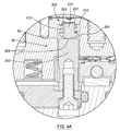
図2〜5に関して、実施形態に係るダイヤフラム密閉バルブタイプのバルブ30が示されている。そのようなバルブは、さまざまなタイプの分析機器、特に、クロマトグラフィー装置やオンライン分析装置に用いられることができる。
2-5, a diaphragm sealed
図2〜5に示されているように、バルブ30は、5つの主要素:バルブキャップ32、バルブ本体33、バルブキャップ32とバルブ本体33との間に圧縮して位置づけられるダイヤフラム36、複数のプランジャー83、及び、作動システム220、を有する。バルブ30は、シリンダー34と底部キャップ40を含んでもよい。または、バルブ本体33を形成し、バルブ本体33に搭載される複数のプランジャー82や作動システム220の作動機構96を取り付けることが可能な他の同等の構成を有してもよい。
2-5, the
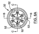
[バルブキャップ]
また、図2〜5、及び、追加の図6A〜6Eに関して、実施形態に係るバルブキャップ32が示されている。図示されている実施形態において、バルブキャップ32は、接合面(以下、バルブキャップ接合面42と称す)を通って延びる複数のプロセス導管44を有する。このバルブキャップ接合面42は、平らで且つ滑らかである。バルブが組み立てられた際(図3〜5に示すように)、バルブキャップ接合面42は、ダイヤフラム36と接する。各プロセス導管44は、バルブキャップ接触面42で開口するプロセスポート46で終わる。実施形態において、プロセスポート46は、バルブキャップ接合面42に環状に設けられている。
[Valve cap]
Also, with respect to FIGS. 2-5 and additional FIGS. 6A-6E, a
図6Cに最良に示すように、実施形態において、プロセス導管44のそれぞれは、配管接続を収容するための大きなねじ穴48と、プロセスポート46で終わる小さな流体通路50と、によって形成されている。
As best shown in FIG. 6C, in the embodiment, each of the
図に示す実施形態では、バルブキャップ32は、シリンダー形状を有し、例えば、限定されることなく、電気化学的に研磨されたステンレス鋼で作られている。また、バルブキャップ32は、ソケット頭部キャップねじ54を収容するねじ穴52を有し、バルブキャップ32をシリンダー34に取り付ける。図4に示されているように、実施形態において、付勢機構55、例えば、限定されることなく、ベルビルワッシャースタック(Belleville washer stack)は、バルブが受けるかもしれない温度変化とは関係なく、バルブキャップ32とバルブ本体33との間のダイヤフラム36上に一定の圧力を維持するために、ソケット頭部キャップねじ54とねじ穴52との間に設けられている。
In the illustrated embodiment, the
もちろん、シリンダー34にバルブキャップ32を保持するために他の配置を考えることができる。任意に、ポリマーの層でバルブキャップ32のバルブキャップ接合面42を覆ってもよい。他の材料で、例えば、セラミックやさまざまな種類のポリマーが、バルブキャップ32又はその一部の材料として使用することができる。バルブキャップ32が、図に示されている実施形態で円筒状のものとは異なる形状、形態、または、構成を有することができることを当業者は理解するだろう。もちろん、バルブキャップの他の実施形態は、4、8、10、12のプロセスポート、または、他の都合のよい数のプロセスポート46を含んでいてもよい。
Of course, other arrangements for holding the
[シリンダー]
図3〜5、および、図7A〜7Dを参照すると、例示を目的として、バルブ30のバルブ本体33のシリンダー34の1つの実施形態が示されている。上述のバルブキャップ32と同様に、シリンダー34は、また接合面(以下、バルブ本体接合面58と称する)を有する。バルブが組み立てられた際(図3〜5に示すように)、バルブ本体接合面58は、バルブキャップのバルブキャップ接合面42と向かい合う。また、バルブ本体接合面58は、滑らでかつ平らである。バルブ本体接合面58は、主要凹部60を備えている。主要凹部60は、バルブキャップ接合面42におけるプロセスポート46の配置と一致する外形を有する。したがって、プロセスポート46がバルブキャップ接合面42上に環状に配置されている図で示されている実施形態において、主要凹部60は、円形の外形である。バルブ構成要素が組み立てられ、バルブが使用できるように準備ができているとき(図3〜5に示すように)、主要凹部60は、バルブキャップ32のプロセスポート46と位置合わせされる。
[cylinder]
3-5 and 7A-7D, for purposes of illustration, one embodiment of a
シリンダーは、複数のプランジャー通路62を有する。複数のプランジャー通路62は、シリンダー34内でそれぞれ延び、2つのプロセスポート46間の主要凹部60における一端で開口する。プランジャー通路62の他端は、バルブ本体キャビティ63で開口する。
The cylinder has a plurality of
また、シリンダー34は、ねじ穴64の第1セットと、ねじ穴64の第2セットと、を有する。ねじ穴64の第1セットは、シリンダー34をバルブキャップに保持するソケット頭部キャップねじ54を収容する(図7Aに最良に示す)。ねじ穴64の第2セットは、シリンダー34を下部キャップ40に保持するソケット頭部キャップねじを収容する(図7Bに最良に示す)。もちろん、シリンダー34をバルブキャップ32や下部キャップ40に取り付ける他の配置にすることもできる。
The
[ダイヤフラム]
図8A〜8Dを参照すると、バルブ30のダイヤフラム36の実施形態が示されている。ダイヤフラム36は、バルブキャップ32と対向する第1面74と、シリンダー34と対向する第2面76と、を有する。バルブが組み立てられ、使用する準備ができたときに(図3〜6に示すように)、すなわち、ダイヤフラムがプロセスポート46にわたって位置づけられているとき、ダイヤフラム46は、バルブキャップ接合面42とバルブ本体接合面58との間に位置づけられる。図8Cでより明確に示されているように、ダイヤフラムは、予め形成された変形78を有することが望ましい。バルブが組み立てられた際に、予め形成された変形78は、シリンダー34の主要凹部60内に横たわっている。ダイヤフラム36の第1面74、および、バルブキャップ32のバルブキャップ接合面42は、プロセスポート46間の伝達通路(communication channel)を定義する。
[Diaphragm]
With reference to FIGS. 8A-8D, an embodiment of the
ダイヤフラム36は、単一のポリマー層又は複数のポリマー層で作られており、薄い金属層があってもなくてもよく、あるいは、金属だけでできていてもよい。例えば、使用することができる金属は、ステンレス鋼316、アルミニウム、クロムニッケル鋼、銅、などである。高ガス気密性を必要とする利用において、複数のポリマー層からなるダイヤフラム36を用いることが好ましい。また、他の利用では、ポリマー層の上に薄い金属層を必要とする。
[漏れ収集(leaks collection)]
図7Cと図7Dに関して、シリンダー34は、また漏れ収集システムを備えていてもよい。漏れ収集システムは、プロセスパージチャンネル(process purging channel)65と、プロセスパージ入口通路66と、プロセスパージ出口通路68と、で構成されている。プロセスパージ入口通路66は、パージラインの入口67に接続されて、プロセスパージ出口通路68は、パージラインの出口69に接続されている。シリンダー34は、さらに、一対の流体入口70と、一対の流体出口72と、を備えていてもよい。一対の流体入口70は、パージラインの入口67に接続され、一対の流体出口72は、パージラインの出口69に接続されている。
[Leaks collection]
With reference to FIGS. 7C and 7D, the
また、シリンダー34は、作動システム220に向かって流体が流れるようにする作動パージ/排出出口通路112を備えていてもよい。パージ/排出出口通路112間の直径の差が、より小さな直径を有するパージ/排出出口通路112からより大きな直径を有するパージ/排出出口通路122に移動する流体の流れの方向を決定する。
The
図6Dに示されているように、パージ循環ラインは、バルブキャップ32のバルブキャップ接合面42で延びる内側環状通路51および外側環状通路53をさらに有することができる。ここで示される実施形態では、流体入口70および流体出口72は、それぞれ、内側環状通路51で開口する第1開口部と、外側環状通路で開口する第2開口部と、を有する。
As shown in FIG. 6D, the purge circulation line can further include an inner
このような漏れ収集システムの操作は、本願の出願者の上述で記載したPCT/CA2008/002138で詳細に記載されており、参照することによりここで組み込まれ、ここではさらに記載しない。 The operation of such a leak collection system is described in detail in the above-mentioned PCT / CA2008 / 002138 of the applicant of the present application and is hereby incorporated by reference and is not further described here.
[プランジャー]
図4、4A、および、4Bを参照すると、バルブ30は、隣接するポート間の伝達(communication)を可能にしたり、防いだりするために、ダイヤフラム36に係合および解放する複数のプランジャー82をさらに備えている。プランジャー82は、それぞれ、シリンダー34のプランジャー通路62の1つに位置づけられている。本明細書の文脈において、用語「プランジャー」は、機械力または流体圧力により、または、機械力または流体圧力に対して、駆動される機械部品やアセンブリを意味することを理解されるだろう。
[Plunger]
With reference to FIGS. 4, 4A and 4B, the
実施形態において、各プランジャー82は、基部200と上部202とで形成されている。基部200は、頭部201で終了する円筒形状であることが好ましい。頭部201は、通路内で上方に突出している。上部202は、ダイヤフラム係合部215と、足部203と、を有することが好ましい。図に示される実施形態では、基部200および上部202は、物理的に付着していないが、接合面205で接触する。接合面205は、基部200の頭部201と上部202の足部203との間で接するように接触点を表す。本明細書では、接するように接触点の用語は、接触する2つの面の接線での接点を意味することを理解するだろう。曲面や平面の場合には、接触点は、平面が同じように接触する曲面の接線である。2つの曲面の場合には、接触点は、2つの曲面が接触する共通接線である。
In the embodiment, each
他の実施形態において、当業者は、基部200の頭部201および上部202の足部203は、基部200の頭部201および上部202の足部203が平らな構造が存在する接合面で接触することを理解するだろう。したがって、この他の実施形態では、それらの間の接触は、接するように接触ではないだろう。
In other embodiments, those skilled in the art will know that the
図4に示すように、図に示されている実施形態では、シリンダー34のプランジャー通路62に相当する範囲内で、上部202がプランジャーの基部200の上に配置されている。基部200の頭部201は、平らな構造を示し、その一方で、上部202の足部203は、丸みを帯びた構造を示す。このため、頭部201と足部203との間の接触は、基部200の平らな頭部201と上部202の丸い足部203との接線で生じる。当業者は、別の実施形態において、基部の頭部201は、丸い構造を示し、その一方で上部の足部203は平らな構造を示すことを理解するだろう。あるいは、それらが、両方丸い構造を示し、それと同時にそれらの間の接するように接触点を提供する。同様に、ベアリングを用いた構成、例えば、以下に記載されるベルビルワッシャサポート(Belleville washer support)や、下部キャップねじ又はピストンや、押し板、に関して、基部200の頭部201と上部202の足部204との間で、それらの構成要素間の接するように接触点を提供するために用いることもできる。
As shown in FIG. 4, in the illustrated embodiment, the
基部200の頭部201と上部202の足部203との間の接点が、接するように接触ではない別の実施形態において、基部200の頭部201および上部202の足部203が、両方とも完全に平らな構成にすることができる。あるいは、基部200の頭部201または上部202の足部203のいずれか一方が、丸い部分と平らな部分の組み合わせで存在することができる。この実施形態では、基部200の頭部201および上部202の足部203が、基部200の頭部201と上部202の足部203の両方が平坦である点で接触する。
In another embodiment where the contact between the
図4、4A、および、4Bをまた参照すると、図に示される実施形態において、バルブ本体33のシリンダー34の各プランジャー通路62は、肩部210を有する。このため、プランジャー通路62は、肩部210とシリンダー34のバルブ本体接合面との間に狭い部分207を有する。そのような肩部210に適合するために、各プランジャー82の上部202は、上部202の足部203と反対側に位置するダイヤフラム係合部215が、肩部210によって定義される狭い部分207内で移動可能なように、サイズ決めされ、形成される。したがって、ダイヤフラム係合部215は、対応する上部202の足部203より狭く、結果として、対応する上部202の足部203がプランジャー通路62で移動可能となるが、狭い部分207に入ることができないような大きさにされている。
Referring also to FIGS. 4, 4A and 4B, in the embodiment shown in the figures, each
圧力が基部200によって上部202にかからない場合、ダイヤフラム36から離れて各プランジャー82の上部202を付勢するために、付勢機構212が、肩部210と上部202の足部203との間に提供される。例えば、限定されることなく、付勢機構は、ダイヤフラム係合部215の一部を囲むスプリング212であることができる。このため、スプリングは、上部202を下方向に付勢し、足部203の上面および肩部210の底面に当接する。
When pressure is not exerted on the
対応する基部200によって圧力がかからない場合、付勢機構が、ダイヤフラム36から離れて各プランジャー82の上部202を付勢するために設けられている限りは、上述のプランジャーの構成が、肩部210なしで適切に機能することを当業者は理解するだろう。
As long as a biasing mechanism is provided to bias the
バルブが作動すると、プランジャー82は、閉位置と開位置との間で、対応する通路62にスライドすることができる。例えば、図4Bにおいて、右側のプランジャーは閉位置で示されている。その一方で、左側のプランジャーは開位置で示されている。
When the valve is actuated, the
閉位置では、プランジャー82は、2つの隣接するポート間でダイヤフラム36と係合する。このため、それらのポート間のコミュニケーションを遮断する。ダイヤフラム36の係合は、上方に動いて上部202を押し付けるプランジャー82の基部200によって達成される。基部200によって加えられる圧力が、付勢機構を弱める。例えば、スプリング212を圧縮することにより、上部202が上方に動かされ、ダイヤフラム係合部215がダイヤフラム36と係合する。
In the closed position, the
開位置では、プランジャー82がダイヤフラム36から離れる。このため、2つの隣接するポート間のコミュニケーションを可能にする。基部200が下方へスライドして上部202から離れると、開位置に到達する。圧力がない、または、不十分な圧力により、底部200によって上部202に圧力がかからない場合、付勢機構は、2つの隣接するポート間のコミュニケーションを可能にするために、ダイヤフラム36から離れて上部202を付勢するために作用する。
In the open position, the
図に示されている実施形態では、底部200とプランジャー82の上部202との両方が、円筒形状である。しかしながら、隣接するポート46間のコミュニケーションが開位置で可能であり、隣接するポート間のコミュニケーションが閉位置で防ぐ、それらが上述の開位置および閉位置となることができる場合には、底部200と上部202は、その円筒形状ではなく他の形状にすることもできると当業者は、理解するだろう。
In the illustrated embodiment, both the bottom 200 and the top 202 of the
プランジャー82の基部200が、シリンダー34のバルブ本体接合面58と完全に垂直でなくても、または、プランジャー82の基部200が、プランジャー82の上部202が完全に一直線になっていなくても、基部200の頭部201と各プランジャー82の上部202の足部203との間の分離は、垂直にダイヤフラム36と接触するプランジャー82の上部202のダイヤフラム係合部215で生じる。また、何らかの理由で、支持構造(以下に記載される)が、シリンダー34のバルブ本体接合面58と完全に平行ではない場合、あるいは、バルブキャップ32とシリンダー34との位置合わせが、完全に調整されていない場合、以下に記載されるように、支持構造が、作動ガスの動作により上に押すときに、プランジャー82の上部202は、シリンダー34のバルブ本体接合面58と垂直なままである。
Even if the
[作動システム]
プランジャー82に関して、開位置と閉位置との間で移動可能にするために、各プランジャー82の基部200は、作動システム220に接続される。各基部200の頭部201がそこから離れて突出するように、基部200は、作動システム220に接続される。例えば、限定されることなく、ねじは、プランジャー82の基部200を作動システム220に取り付けるために用いることができる。
[Operating system]
With respect to the
図3に最良に示すように、実施形態において、作動システム220は、プッシュ板88および第1ピストン92を備えた第1支持構造87と、第2ピストン90を備えた第2支持構造89と、を有する。図に示されるように、第1ピストン92は、第2ピストン90の下に位置づけられている。簡単にするために、それら2つのピストンは、以下それぞれ下部ピストン92と上部ピストン90とする。
As best shown in FIG. 3, in an embodiment, the
図に示されている実施形態において、各プランジャー82は、通常閉じているか、通常開いている。通常閉じたプランジャーの基部200は、プッシュ板88に取り付けられており、通常開いたプランジャーの基部200は、第2ピストン90に取り付けられている。
In the illustrated embodiment, each
プッシュ板88は、シリンダー34のバルブ本体接合面58と平行、すなわち、プランジャー通路62とシリンダー34の中心軸と垂直に、シリンダー34のキャビティ63内に延びている。プッシュ板88は、バルブ本体接合面58と横方向に移動可能であり、言い換えると、シリンダー34の中心軸と平行に移動可能である。通常閉じたプランジャー82の底部200は、プッシュ板88に取り付けられている。複数のキャビティは、通常開いたプランジャー82の底部200がそこを通って動くことができるように、プッシュ板88と交差して延びている。上部ピストン90は、プッシュ板の下に隣接して延びている。通常開いたプランジャー82の底部200は、そこに取り付けられている。下部ピストン92は、隣接する上部ピストン90の下で延びている。
The
図3および3Aに示されているように、プッシュ板88は、ベアリング収容部230を備えている。ベアリング収容部230は、プッシュ板88の右側端部232と左側端部234との間の中心に設けられている。ベアリング収容部230は、プッシュ板88の底壁238に位置づけられおり、それにより、下方に延びるキャビティを形成する。ベアリング収容部230で形成されるキャビティは、ベアリング236の第1部分を収容するサイズと形状である。用語「ベアリング」は、隣接する面の間の回転接触を提供するために、硬化材料で作られ、かつ、滑らかな表面を有する球形の本体またはボールを参照するために用いられていることが、この明細書において、理解されるだろう。ベアリング236の第2部分は、底壁238から離れて下方に突出している。この第2部分は、突出部242として称する。ベアリング236のサイズは、第1部分がベアリング収容部230の内側に密接に合うようにすることができる。このため、2つの構成要素間の緩みを防ぐことができると共に、ベアリング236がそこで自由に回転することができる。下部ピストン92は、ベアリング236と下部ピストン92の上部240との間の単一の接するように接触点244でプッシュ板88と係合する。接するように接触点244は、ベアリング236の円形の形状、および、下部ピストン92の上部240の平らな形状、で提供され、下部ピストン92とプッシュ板88との間の回転接触を可能にする。そのような構成は、プランジャー82がダイヤフラム36に対して押された場合、プッシュ板88を自動的に再度中心に配置することができることにより、シリンダー34のキャビティ63内で、プッシュ板88の位置ずれを防ぎ、結果として、プランジャー82の位置ずれを防ぐ。
As shown in FIGS. 3 and 3A, the
図に示される実施形態において、接触点で高硬度材料を提供するために、下部ピストン92の上部240は、ステンレス鋼17−4PHのような硬化材料で作られた分離部品である。しかしながら、実施形態において、上部240は、下部ピストン92と一体とすることもできる。
In the illustrated embodiment, the
上部ピストン90および下部ピストン92をシリンダー34の内面で適切に密閉するために、Oリングが、各ピストンの外形で提供されることが望ましい。図に示される実施形態において、上部ピストン90または下部ピストン92のいずれかが、後退した場合、そこに取り付けられたプランジャー82の対応する底部200が、下方に引っ張られ、結果として、上部202にかかる圧力の放出となる。
In order to properly seal the
図3に示されているように、下部ピストン92が上方に付勢され、かつ、上部ピストン90が下方に付勢されるように、付勢機構94が設けられている。実施形態では、ベルビルワッシャサポート101およびベルビルワッシャアセンブリ100は、下部ピストン92を上方に付勢するために協力する。底部キャップロードねじ102は、ベルビルワッシャサポート101で上方の力(押し上げ力)を制御するために設けられている。また、実施形態によれば、上部ピストン90をこえて延びている波形スプリング104は、下方の力を上部ピストン90にかける。このため、上部ピストン90を下方向に付勢する。別の実施形態では、異なる付勢アセンブリは、下部ピストン92を上方向に、かつ、上部ピストン90を下方向に、付勢するために設けられていることは、当業者は理解するだろう。
As shown in FIG. 3, an
プランジャーを作動するために、作動機構96は、上部ピストン90と下部ピストン92との間の距離または空間を制御するために提供される。この実施形態では、作動機構96は、開位置と閉位置との間でプランジャー82を作動する。作動機構96は、例えば、上部ピストン90と下部ピストン92との間の作動ガスの注入によって動かす空気圧式アクチュエータである。
In order to actuate the plunger, an
図3および3Bに示されているように、下部キャップ40は、シリンダー34に取り付けられており、ソケット頭部キャップねじで取り付けられることが好ましい。また、下部キャップ40は、底部キャップロードねじ102を収容する。底部キャップロードねじ102は、ベルビルワッシャサポート101およびベルビルワッシャアセンブリ100を用いて下部ピストン92にかかる圧力の調整を可能にする。ベルビルワッシャサポート101に下部キャップロードねじ102による圧力の後で作動システム220の位置合わせを容易にするために、ベルビルワッシャサポート101は、ベアリング収容部130を備えることができる。ベアリング収容部130は、右端部132と左端部134との間の水平方向に中央に配置されている。ベアリング収容部130は、ベルビルワッシャサポート101の底壁138に配置されており、下向きに延びるキャビティを形成する。ベアリング収容部130で形成されるキャビティは、ベアリング136の第1部分を収容するようなサイズと形状である。ベアリング136の第2部分は、ベルビルワッシャサポート101の底壁138から離れて下方向に突出している。この第2部分は、突出部140として称する。ベアリング136のサイズは、ベアリング収容部130の内側に密接に合うようになっている。このため、ベアリング136とベアリング収容部130との間の緩みを防ぐことができるとともに、ベアリング136がそこで自由に回転することができる。底部キャップロードねじ102は、ベアリング136と底部キャップロードねじ102の上部131との間の単一の接するように接触点142でベルビルワッシャサポート101と係合する。接するように接触点142は、ベアリング136の円形の形状、および、底部キャップロードねじ102の上部131の平らな形状、で提供されている。単一の接するように接触点142は、ベルビルワッシャサポート101における中心を外れた圧力で働く底部キャップロードねじ102によって生じる作動システムの位置ずれや下部ピストン92の位置ずれを防ぐ。所定の位置に底部キャップロードねじ102を固定するために用いられる固定ねじ103は、その中央の位置から底部キャップロードねじ102の位置を変える傾向があるので、ベルビルワッシャサポート101でそのような底部キャップロードねじ102の中心を外れた圧力は、従来のバルブで起こる。
As shown in FIGS. 3 and 3B, the
実施形態では、また、下部キャップ40は、下部ピストン92と下部キャップ40との間で増加する圧力を防ぐために、下部キャップ作動排出口114を有することができる。下部キャップ作動排出口114は、そこで延び、作動機構96と反対に配置されている。
In an embodiment, the
そのような作動排出口114の操作は、本出願人の上述した出願PCT/CA2009/001783で詳細に記載されており、参照することでここに組み込まれ、ここでは詳細に記載しない。
The operation of such an
好ましい作動システムは、ここで記載されているが、別の実施形態において、閉位置と開位置との間のプランジャーの動作となる他の作動システムを用いることができることを当業者は理解するだろう。 Although a preferred actuation system is described herein, those skilled in the art will appreciate that in other embodiments, other actuation systems that result in plunger motion between the closed and open positions can be used. Let's go.
[固定機構]
ダイヤフラムバルブは、しばしば構築され、十分にテストされた後、それらはプラスチック製のパッケージに密閉され、顧客に出荷する前に梱包されて、在庫室(inventory)に格納される。このような市場の需要、在庫管理、顧客ニーズ等のさまざまな要因に依存して、バルブは、その製造後数週間または数ヶ月未使用のままと考えられる。また、ある状況では、バルブの所有者が一時的にシャットダウンすることがあり、または、使用中再度それを置く前に、不確定の時間で積極的な使用(active use)からバルブを取り外すことがある。バルブがアイドルの際(図4Bに示されているように)、その通常開いたプランジャーがそれらの閉位置にあり、このためダイヤフラム上に一定の圧力を加える。また、ダイヤフラム材料に応じて、ダイヤフラムの永久変形をもたらし、バルブの効率を低下させる。したがって、固定機構は、バルブが使用されていない場合、それらの開位置において(図4に示すように)プランジャー82の通常閉じた基部200を固定するのに有利である。
[Fixing mechanism]
Diaphragm valves are often built and fully tested, then they are sealed in plastic packages, packed before shipping to customers, and stored in an inventory. Depending on various factors such as market demand, inventory management, customer needs, etc., the valve may remain unused for weeks or months after its manufacture. Also, in certain circumstances, the valve owner may shut down temporarily or remove the valve from active use at an indeterminate time before putting it back in use. is there. When the valve is idle (as shown in FIG. 4B), its normally open plunger is in their closed position, thus applying a constant pressure on the diaphragm. Also, depending on the diaphragm material, it will cause permanent deformation of the diaphragm and reduce the efficiency of the valve. Thus, the locking mechanism is advantageous for locking the normally closed
実施形態では、固定機構119は、通常閉じたプランジャー82の基部200が開位置にあるとき、第1支持構造87と有利に係合する。このため、付勢機構94に対して動作し、上部202がダイヤフラム36に対して押される閉位置にプランジャー82が到達することを物理的に防ぐ。当業者によって理解されるように、そのような固定機構119の使用は、バルブ30が使用中でない場合に、閉じたプランジャー82が変形したり、圧縮したり、あるいは、ダイヤフラム36に作用することを防ぐことに、有利に用いることができる。
In an embodiment, the
そのような固定機構119は、また、有利に、メンテナンス等の際に、ダイヤフラムの交換を容易にすることが理解されるだろう。使用者が、バルブ本体内でプランジャーの通常開いた基部200を保持するのを可能にすることによって、プランジャーがダイヤフラムの適切な位置決めを妨げないことを確保することができる。
It will be appreciated that such a
そのような固定機構の異なる可能な実施形態は、本出願人の上述のPCT/CA2009/001783に詳細に記載されており、参照することによりここに組み込まれ、ここでは詳細に記載しない。 Different possible embodiments of such a locking mechanism are described in detail in Applicant's above-mentioned PCT / CA2009 / 001783, incorporated herein by reference and not described in detail here.
いくつかの代替実施形態および実施例は、本明細書に図示および記載されている。上述の実施形態は、単に例を示しただけである。当業者は、別の実施形態の特徴、構成要素の可能な組み合わせとバリエーションを理解するだろう。当業者は、さらに、他の実施形態が、ここで示される別の実施形態を組み合わせることができることを理解するだろう。本発明は、その中心的特徴から逸脱することなく他の特定の形態で実施され得ることが理解される。したがって、本実施例および実施形態は、例示であり、限定的ではないすべての点で考えられるべきであり、また、本発明は、実施形態に限定されるものではない。即ち、本発明の骨子を逸脱しない範囲で種々変形して実施することができる。 Several alternative embodiments and examples are illustrated and described herein. The above-described embodiments are merely examples. Those skilled in the art will appreciate the features of alternative embodiments, possible combinations and variations of components. One skilled in the art will further appreciate that other embodiments can be combined with other embodiments shown herein. It will be understood that the invention may be embodied in other specific forms without departing from its central characteristics. Therefore, this Example and embodiment should be considered in all points which are illustration and are not restrictive, and the present invention is not limited to an embodiment. That is, various modifications can be made without departing from the scope of the present invention.
30 バルブ
32 バルブキャップ
33 バルブ本体
34 シリンダー
36 ダイヤフラム
40 下部キャップ
42 接合面(バルブキャップ接合面)
44 プロセス導管
46 プロセスポート
48 ねじ穴
50 流体通路
52、64 ねじ穴
55 付勢機構
58 バルブ本体接合面
62 プランジャー通路
82 プランジャー
87 第1支持構造
88 プッシュ板
89 第2支持構造
90 第2ピストン(上部ピストン)
92 第1ピストン(下部ピストン)
94 付勢機構
96 作動機構
100 ベルビルワッシャアセンブリ
101 ベルビルワッシャサポート
102 底部キャップロードねじ
104 波形スプリング
130、230 ベアリング収容部
200 基部、底部
201 頭部
202 上部
203 足部
205 接合面
207 狭い部分
210 肩部
212 付勢機構
215 ダイヤフラム係合部
220 作動システム
236 ベアリング
238 底壁
240 上部
242 突出部
244 接触点
30
44
92 1st piston (lower piston)
94
Claims (27)
前記バルブキャップは、貫通する複数のプロセス導管を備え、前記複数のプロセス導管のそれぞれは、バルブキャップ接合面におけるプロセスポートで終了し、
前記バルブ本体は、前記バルブキャップ接合面と対向するバルブ本体接合面と、そこで延びる複数のプランジャー通路と、を備え、
前記ダイヤフラムは、前記バルブキャップ接合面と前記バルブ本体接合面との間に前記プロセスポートと交差するように位置づけられており、
前記複数のプランジャーのそれぞれは、前記複数のプランジャー通路の対応するプランジャー通路に位置づけられ、前記プランジャーが前記ダイヤフラムと係合する閉位置と前記プランジャーが前記ダイヤフラムから離れる開位置との間で移動可能であり、
前記作動システムは、前記閉位置と前記開位置との間で前記複数のプランジャーのそれぞれを動かし、
前記複数のプランジャーのそれぞれは、
(i)前記作動システムに接続され、そこから離れて突出する頭部を有する基部と、
(ii)前記基部と前記ダイヤフラムとの間で延び、前記基部の頭部と接する足部を有する上部と、
(iii)前記プランジャーが開位置にある場合、前記ダイヤフラムから離れて前記上部を付勢するプランジャー付勢機構と、を有する
ことを特徴とするバルブ。 A valve having a valve cap, a valve body, a diaphragm, a plurality of plungers, and an actuation system;
The valve cap includes a plurality of process conduits therethrough, each of the plurality of process conduits terminating at a process port at a valve cap interface.
The valve body includes a valve body joint surface facing the valve cap joint surface, and a plurality of plunger passages extending therethrough,
The diaphragm is positioned so as to intersect the process port between the valve cap joint surface and the valve body joint surface,
Each of the plurality of plungers is positioned in a corresponding plunger passage of the plurality of plunger passages, and has a closed position where the plunger engages the diaphragm and an open position where the plunger leaves the diaphragm. Can be moved between,
The actuation system moves each of the plurality of plungers between the closed position and the open position;
Each of the plurality of plungers is
(I) a base having a head connected to the operating system and protruding away therefrom;
(Ii) an upper portion having a foot portion extending between the base portion and the diaphragm and in contact with a head portion of the base portion;
(Iii) a valve having a plunger urging mechanism that urges the upper part away from the diaphragm when the plunger is in the open position.
ことを特徴とする請求項1に記載のバルブ。 The valve according to claim 1, wherein the upper foot is in contact with the head of the base.
ことを特徴とする請求項2に記載のバルブ。 The valve according to claim 2, wherein at least one of the head of the base or the upper foot has a circular structure, and the other has a flat or circular structure.
前記上部の足部が、円形構造である
ことを特徴とする請求項3に記載のバルブ。 The head of the base has a flat structure;
The valve according to claim 3, wherein the upper foot has a circular structure.
前記肩部が、前記肩部と前記バルブ本体接合面との間の前記通路のより狭い部分を定義し、
前記複数のプランジャーのそれぞれの上部が、前記上部のダイヤフラム係合部が前記足部より狭く、かつ、前記通路のより狭い部分で移動可能なサイズと形状である
ことを特徴とする請求項1〜4のいずれか一項に記載のバルブ。 Each of the plurality of plunger passages of the valve body has a shoulder,
The shoulder defines a narrower portion of the passage between the shoulder and the valve body interface;
The upper portion of each of the plurality of plungers has a size and shape that allows the upper diaphragm engaging portion to be narrower than the foot portion and move in a narrower portion of the passage. The valve as described in any one of -4.
ことを特徴とする請求項5に記載のバルブ。 The plunger urging mechanism of each of the plurality of plungers is disposed between one shoulder portion of the corresponding plurality of plunger passages and the upper foot portion of the plunger. The valve according to claim 5.
ことを特徴とする請求項6に記載のバルブ。 The valve according to claim 6, wherein the plunger urging mechanism is a spring.
ことを特徴とする請求項1〜7にいずれか一項に記載のバルブ。 The valve according to any one of claims 1 to 7, wherein the operation system includes a piston.
前記プッシュ板は、そこに形成される水平方向に中心に配置されるベアリング収容部を備え、前記複数のプランジャーの少なくとも1つが、前記プッシュ板に取り付けられ、
前記ベアリングは、前記プッシュ板のベアリング収容部に位置づけられそこから突出し、
前記ベアリングの突出する突出部は、前記ピストンと接するように接触し、前記ピストンと前記プッシュ板との間で単一の接触点である
ことを特徴とする請求項8に記載のバルブ。 The operating system further includes a push plate and a bearing,
The push plate includes a bearing receiving portion that is formed in a horizontal center formed therein, and at least one of the plurality of plungers is attached to the push plate,
The bearing is positioned in a bearing receiving portion of the push plate and protrudes therefrom;
The valve according to claim 8, wherein the protruding portion of the bearing protrudes in contact with the piston and is a single contact point between the piston and the push plate.
前記ピストン付勢機構が、そこに形成される水平方向に中心に配置されるベアリング収容部を備えた支持部と、前記支持部の一部と前記ピストンとの間に位置づけられるピストン付勢要素と、前記ピストンに向かって支持部を調節可能に押圧する底部キャップねじと、前記支持部のベアリング収容部に配置されてそこから突出するベアリングと、を有し、
前記ベアリングの突出する突出部は、前記底部キャップねじと接するように接触し、前記支持部と前記底部キャップねじとの間で単一の接触点である
ことを特徴とする請求項8又は9に記載のバルブ。 The actuation system further includes a piston biasing mechanism that biases the piston of the actuation system upward,
The piston urging mechanism includes a support portion including a bearing housing portion disposed in the center in the horizontal direction, and a piston urging element positioned between a part of the support portion and the piston. A bottom cap screw that adjustably presses the support toward the piston, and a bearing disposed in and projecting from the bearing housing of the support,
10. The protruding portion of the bearing is in contact with the bottom cap screw, and is a single contact point between the support portion and the bottom cap screw. The valve described.
ことを特徴とする請求項10に記載のバルブ。 The valve according to claim 10, wherein the support portion is a Belleville washer support, and the piston biasing element is a Belleville washer assembly.
前記バルブキャップは、貫通する複数のプロセス通路を備え、
前記複数のプロセス通路のそれぞれが、バルブキャップ接合面におけるプロセスポートで終わり、
バルブが、前記プロセスポートと交差して位置づけられるダイヤフラムをさらに有し、
前記バルブアセンブリが、前記バルブキャップ接合面と対向するバルブ本体接合面を有するバルブ本体と、複数のプランジャーと、作動システムと、を有し、
前記バルブ本体が、そこで延びる複数のプランジャー通路を備え、
前記複数のプランジャーのそれぞれが、前記複数のプランジャー通路の対応するプランジャー通路に位置づけられ、前記プランジャーが前記ダイヤフラムと係合する閉位置と前記プランジャーが前記ダイヤフラムから離れる開位置との間で移動可能であり、
前記作動システムが、前記閉位置と前記開位置との間で前記複数のプランジャーのそれぞれを動かし、
前記複数のプランジャーのそれぞれは、
(i)前記作動システムに接続され、そこから離れて突出する頭部を有する基部と、
(ii)前記基部と前記ダイヤフラムとの間で延び、前記基部の頭部で接する足部を有する上部と、
(iii)前記プランジャーが閉位置にある場合、前記ダイヤフラムから離れて前記上部を付勢する付勢機構と、を有する
ことを特徴とするバルブキャップを有するバルブ用バルブアセンブリ。 A valve assembly for a valve having a valve cap,
The valve cap includes a plurality of process passages therethrough,
Each of the plurality of process passages terminates in a process port at a valve cap interface;
The valve further comprises a diaphragm positioned across the process port;
The valve assembly includes a valve body having a valve body joint surface facing the valve cap joint surface, a plurality of plungers, and an actuation system;
The valve body includes a plurality of plunger passages extending therethrough;
Each of the plurality of plungers is positioned in a corresponding plunger passage of the plurality of plunger passages, and a closed position in which the plunger engages the diaphragm and an open position in which the plunger leaves the diaphragm. Can be moved between,
The actuation system moves each of the plurality of plungers between the closed position and the open position;
Each of the plurality of plungers is
(I) a base having a head connected to the operating system and protruding away therefrom;
(Ii) an upper portion having a foot portion extending between the base portion and the diaphragm and contacting the head portion of the base portion;
(Iii) an urging mechanism for urging the upper portion away from the diaphragm when the plunger is in a closed position; and a valve assembly for a valve having a valve cap.
ことを特徴とする請求項12に記載のバルブアセンブリ。 The valve assembly according to claim 12, wherein the upper foot portion is in contact with the head portion of the base portion.
ことを特徴とする請求項13に記載のバルブアセンブリ。 14. The valve assembly according to claim 13, wherein at least one of the head of the base or the upper foot has a circular structure, and the other has a flat or circular structure. .
前記上部の足部が、円形構造である
ことを特徴とする請求項14に記載のバルブアセンブリ。 The head of the base has a flat structure;
The valve assembly according to claim 14, wherein the upper foot has a circular structure.
前記肩部が、前記肩部と前記バルブ本体接合面との間の前記プランジャー通路のより狭い部分を定義し、
前記複数のプランジャーのそれぞれの上部が、前記上部のダイヤフラム係合部が前記足部より狭く、前記通路のより狭い部分で移動可能なサイズと形状である
ことを特徴とする請求項12〜15のいずれか一項に記載のバルブアセンブリ。 Each of the plurality of plunger passages of the valve body has a shoulder,
The shoulder defines a narrower portion of the plunger passage between the shoulder and the valve body interface;
The upper part of each of the plurality of plungers has a size and a shape in which the upper diaphragm engaging part is narrower than the foot part and is movable in a narrower part of the passage. The valve assembly according to any one of the preceding claims.
ことを特徴とする請求項16に記載のバルブアセンブリ。 The biasing mechanism of each of the plurality of plungers is disposed between one shoulder portion of the corresponding plurality of plunger passages and a foot portion on the top of the plunger. The valve assembly according to claim 16.
ことを特徴とする請求項17に記載のバルブアセンブリ。 The valve assembly according to claim 17, wherein the biasing mechanism is a spring.
ことを特徴とする請求項12〜18のいずれか一項に記載のバルブアセンブリ。 The valve assembly according to any one of claims 12 to 18, wherein the operating system comprises a piston.
前記プッシュ板は、そこに形成される水平方向に中心に配置されるベアリング収容部を備え、前記複数のプランジャーの少なくとも1つが、前記プッシュ板に取り付けられ、
前記ベアリングは、前記プッシュ板のベアリング収容部に位置づけられそこから突出し、
前記ベアリングの突出する突出部が、前記ピストンと接するように接触し、前記ピストンと前記プッシュ板との間の単一の接触点である
ことを特徴とする請求項19に記載のバルブアセンブリ。 The actuation system further comprises a push plate and a bearing;
The push plate includes a bearing receiving portion that is formed in a horizontal center formed therein, and at least one of the plurality of plungers is attached to the push plate,
The bearing is positioned in a bearing receiving portion of the push plate and protrudes therefrom;
The valve assembly according to claim 19, wherein the protruding protrusion of the bearing is in contact with the piston and is a single contact point between the piston and the push plate.
前記ピストン付勢機構が、そこに形成される水平方向に中心に配置されるベアリング収容部を備えた支持部と、前記支持部の一部と前記ピストンとの間に位置づけられるピストン付勢要素と、前記ピストンに向かって支持部を調節可能に押圧する底部キャップねじと、前記支持部のベアリング収容部に配置されてそこから突出するベアリングと、を有し、
前記ベアリングの突出する突出部は、前記底部キャップねじと接するように接触し、前記支持部と前記底部キャップねじとの間で単一の接触点である
ことを特徴とする請求項19又は20に記載のバルブアセンブリ。 The actuation system further includes a piston biasing mechanism that biases the piston of the actuation system upward,
The piston urging mechanism includes a support portion including a bearing housing portion disposed in the center in the horizontal direction, and a piston urging element positioned between a part of the support portion and the piston. A bottom cap screw that adjustably presses the support toward the piston, and a bearing disposed in and projecting from the bearing housing of the support,
21. The protruding portion of the bearing is in contact with the bottom cap screw and is a single contact point between the support portion and the bottom cap screw. The valve assembly as described.
前記バルブキャップは、貫通する複数のプロセス導管を備え、
前記プロセス導管のそれぞれが、バルブキャップ接合面におけるプロセスポートで終わり、
前記バルブ本体が、前記バルブキャップ接合面と対向するバルブ本体接合面と、そこで延びる複数のプランジャー通路と、を備え、
前記ダイヤフラムは、前記バルブキャップ接合面と前記バルブ本体接合面との間に前記プロセスポートと交差するように位置づけられており、
前記複数のプランジャー通路のそれぞれは、前記複数のプランジャー通路の対応するプランジャー通路に位置づけられ、前記プランジャーが前記ダイヤフラムと係合する閉位置と前記プランジャーが前記ダイヤフラムから離れる開位置との間で移動可能であり、
前記作動システムが、前記閉位置と前記開位置との間で前記複数のプランジャーのそれぞれを動かし、そこで形成される水平方向に中心に配置されるベアリング収容部を備えた第1作動構成要素と、前記第1作動構成要素のベアリング収容部に配置されそこから突出する第1ベアリングと、で構成され、
前記第1ベアリングの突出する突出部が、前記作動システムの第2作動構成要素と接するように接触し、前記第1作動構成要素と前記第2作動構成要素との間で単一の接触点であり、
前記付勢機構が、前記作動システムの第2作動構成要素を上方向に付勢し、そこで形成される水平方向に中央に配置されるベアリング収容部を有する第1付勢構成要素と、前記第1付勢構成要素の一部と前記第2作動構成要素との間に位置づけられる付勢要素と、前記第1付勢構成要素のベアリング収容部に配置されそこから突出する第2ベアリングと、で構成され、
前記第2ベアリングの突出する突出部が、前記付勢機構の第2付勢構成要素と接するように接触し、前記第1付勢構成要素と前記第2付勢構成要素との間で単一の接触点である
ことを特徴とするバルブ。 A valve having a valve cap, a valve body, a diaphragm, a plurality of plungers, an actuation system, and a biasing mechanism;
The valve cap includes a plurality of process conduits therethrough,
Each of the process conduits terminates in a process port at the valve cap interface,
The valve body includes a valve body joint surface facing the valve cap joint surface, and a plurality of plunger passages extending therethrough,
The diaphragm is positioned so as to intersect the process port between the valve cap joint surface and the valve body joint surface,
Each of the plurality of plunger passages is positioned in a corresponding plunger passage of the plurality of plunger passages, a closed position in which the plunger engages the diaphragm, and an open position in which the plunger leaves the diaphragm. Is movable between
The actuating system moves each of the plurality of plungers between the closed position and the open position, and includes a first actuating component comprising a horizontally-centered bearing housing formed therein; A first bearing disposed in and projecting from the bearing housing portion of the first actuating component,
A protruding protrusion of the first bearing contacts and contacts a second operating component of the operating system, at a single point of contact between the first operating component and the second operating component. Yes,
The biasing mechanism biases the second actuating component of the actuating system upward, and includes a first biasing component having a bearing housing portion formed therein and horizontally disposed at the center; A biasing element positioned between a portion of one biasing component and the second actuation component; and a second bearing disposed in and projecting from a bearing housing portion of the first biasing component Configured,
The protruding portion of the second bearing protrudes into contact with the second urging component of the urging mechanism , and is single between the first urging component and the second urging component. A valve characterized by being a contact point.
前記第2作動構成要素が、ピストンであり、
前記第1付勢構成要素が、支持部であり、
前記第2付勢構成要素が、底部キャップねじである
ことを特徴とする請求項22に記載のバルブ。 The first actuating component is a push plate;
The second actuating component is a piston;
The first biasing component is a support;
23. The valve of claim 22, wherein the second biasing component is a bottom cap screw.
前記付勢要素が、ベルビルワッシャアセンブリである
ことを特徴とする請求項23に記載のバルブ The support is a Belleville washer support;
24. The valve of claim 23, wherein the biasing element is a Belleville washer assembly.
前記バルブキャップは、貫通する複数のプロセス導管を備え、
前記複数のプロセス導管のそれぞれは、バルブキャップ接合面におけるプロセスポートで終了し、
前記バルブ本体は、前記バルブキャップ接合面と対向するバルブ本体接合面と、そこで延びる複数のプランジャー通路と、を備え、
前記ダイヤフラムは、前記バルブキャップ接合面と前記バルブ本体接合面との間に前記プロセスポートと交差するように位置づけられており、
前記複数のプランジャーのそれぞれが、前記複数のプランジャー通路の対応するプランジャー通路に位置づけられ、前記プランジャーが前記ダイヤフラムと係合する閉位置と前記プランジャーが前記ダイヤフラムから離れる開位置との間で移動可能であり、
前記作動システムが、前記閉位置と前記開位置との間で前記複数のプランジャーのそれぞれを動かし、
前記作動システムが、ピストンと、そこで形成される水平方向に中心に配置されるベアリング収容部を備えたプッシュ板と、前記プッシュ板のベアリング収容部に配置されそこから突出するベアリングと、を有し、
前記複数のプランジャーの少なくとも1つが、前記プッシュ板に取り付けられており、
前記ベアリングの突出する突出部が、前記ピストンと接するように接触し、前記ピストンと前記プッシュ板との間で単一の接触点である
ことを特徴とするバルブ。 A valve having a valve cap, a valve body, a diaphragm, a plurality of plungers, and an actuation system;
The valve cap includes a plurality of process conduits therethrough,
Each of the plurality of process conduits terminates in a process port at a valve cap interface;
The valve body includes a valve body joint surface facing the valve cap joint surface, and a plurality of plunger passages extending therethrough,
The diaphragm is positioned so as to intersect the process port between the valve cap joint surface and the valve body joint surface,
Each of the plurality of plungers is positioned in a corresponding plunger passage of the plurality of plunger passages, and a closed position in which the plunger engages the diaphragm and an open position in which the plunger leaves the diaphragm. Can be moved between,
The actuation system moves each of the plurality of plungers between the closed position and the open position;
The actuating system includes a piston, a push plate having a bearing housing portion formed in the horizontal center formed therein, and a bearing disposed in and projecting from the bearing housing portion of the push plate. ,
At least one of the plurality of plungers is attached to the push plate;
The valve | bulb which the protrusion part which the said protrusion protrudes contacts so that it may contact | connect the said piston, and is a single contact point between the said piston and the said push board.
前記バルブキャップは、貫通する複数のプロセス導管を備え、
前記複数のプロセス導管のそれぞれは、バルブキャップ接合面におけるプロセスポートで終了し、
前記バルブ本体は、前記バルブキャップ接合面と対向するバルブ本体接合面と、そこで延びる複数のプランジャー通路と、を備え、
前記ダイヤフラムは、前記バルブキャップ接合面と前記バルブ本体接合面との間に前記プロセスポートと交差するように位置づけられており、
前記複数のプランジャーのそれぞれは、前記複数のプランジャー通路の対応するプランジャー通路に位置づけられ、前記プランジャーが前記ダイヤフラムと係合する閉位置と前記プランジャーが前記ダイヤフラムから離れる開位置との間で移動可能であり、
前記作動システムが、前記閉位置と前記開位置との間で前記複数のプランジャーのそれぞれを動かし、
前記作動システムが、ピストンを有し、
前記付勢機構が、前記作動システムのピストンを上方向に付勢し、
前記付勢機構が、そこに形成される水平方向に中心に配置されるベアリング収容部を備えた支持部と、前記支持部の一部と前記ピストンとの間に位置づけられるピストン付勢要素と、前記ピストンに向かって前記支持部を調整可能に押す底部キャップねじと、前記支持部の前記ベアリング収容部内に配置され、そこから突出するベアリングと、を有し、
前記ベアリングの突出する突出部が、前記底部キャップねじと接するように接触し、前記支持部と前記底部キャップねじとの間で単一の接触点である
ことを特徴とするバルブ。 A valve having a valve cap, a valve body, a diaphragm, a plurality of plungers, an actuation system, and a biasing mechanism;
The valve cap includes a plurality of process conduits therethrough,
Each of the plurality of process conduits terminates in a process port at a valve cap interface;
The valve body includes a valve body joint surface facing the valve cap joint surface, and a plurality of plunger passages extending therethrough,
The diaphragm is positioned so as to intersect the process port between the valve cap joint surface and the valve body joint surface,
Each of the plurality of plungers is positioned in a corresponding plunger passage of the plurality of plunger passages, and has a closed position where the plunger engages the diaphragm and an open position where the plunger leaves the diaphragm. Can be moved between,
The actuation system moves each of the plurality of plungers between the closed position and the open position;
The actuation system has a piston;
The biasing mechanism biases the piston of the operating system upward;
A support portion having a bearing housing portion formed in the horizontal direction in the biasing mechanism; a piston biasing element positioned between a part of the support portion and the piston; a bottom cap screw press adjustably the support portion toward the piston, wherein arranged in the bearing housing portion of the support portion, anda bearings protruding therefrom,
The protruding portion of the bearing protrudes into contact with the bottom cap screw, and is a single contact point between the support portion and the bottom cap screw.
前記ピストン付勢要素が、ベルビルワッシャアセンブリである
ことを特徴とする請求項26に記載のバルブ。 The support is a Belleville washer support;
The valve of claim 26, wherein the piston biasing element is a Belleville washer assembly.
Applications Claiming Priority (3)
| Application Number | Priority Date | Filing Date | Title |
|---|---|---|---|
| US201261599553P | 2012-02-16 | 2012-02-16 | |
| US61/599,553 | 2012-02-16 | ||
| PCT/CA2013/050124 WO2013120208A1 (en) | 2012-02-16 | 2013-02-18 | Diaphragm-sealed valve with improved actuator design |
Publications (3)
| Publication Number | Publication Date |
|---|---|
| JP2015507159A JP2015507159A (en) | 2015-03-05 |
| JP2015507159A5 JP2015507159A5 (en) | 2016-02-18 |
| JP6101713B2 true JP6101713B2 (en) | 2017-03-22 |
Family
ID=48983506
Family Applications (1)
| Application Number | Title | Priority Date | Filing Date |
|---|---|---|---|
| JP2014556892A Active JP6101713B2 (en) | 2012-02-16 | 2013-02-18 | Diaphragm sealing valve with improved actuator structure |
Country Status (6)
| Country | Link |
|---|---|
| US (1) | US9377444B2 (en) |
| EP (1) | EP2815160A4 (en) |
| JP (1) | JP6101713B2 (en) |
| CN (1) | CN104271996B (en) |
| CA (1) | CA2863891C (en) |
| WO (1) | WO2013120208A1 (en) |
Families Citing this family (4)
| Publication number | Priority date | Publication date | Assignee | Title |
|---|---|---|---|---|
| JP2016509242A (en) * | 2013-03-11 | 2016-03-24 | メカニック・アナリティック・インコーポレーテッド | Diaphragm valve with sealing assembly, chromatographic system including the same, and method of operating the same |
| WO2019144228A1 (en) | 2018-01-23 | 2019-08-01 | Ldetek Inc. | Valve assembly for a gas chromatograph |
| CA3125342C (en) * | 2019-02-07 | 2022-02-22 | Apn Inc. | Sample injection diaphragm valve |
| US11788994B2 (en) * | 2019-12-18 | 2023-10-17 | Mécanique Analytique Inc. | Pulsing purge diaphragm valve and related method |
Family Cites Families (12)
| Publication number | Priority date | Publication date | Assignee | Title |
|---|---|---|---|---|
| DE1171177B (en) * | 1961-08-18 | 1964-05-27 | Bodenseewerk Perkin Elmer Co | Three-way switch valve for gas chromatograph |
| US3297053A (en) | 1963-12-30 | 1967-01-10 | Carle Instr Inc | Selector valve |
| US4795130A (en) * | 1982-09-24 | 1989-01-03 | Applied Automation, Inc. | Piston biasing means |
| US4550742A (en) * | 1984-01-23 | 1985-11-05 | Stearns Stanley D | Variable tensioning system for shear seal valves |
| US5601115A (en) * | 1995-05-31 | 1997-02-11 | Vantege Technologies, Inc. | Multiport sampling valve |
| US6202698B1 (en) * | 1997-06-18 | 2001-03-20 | Valco Instruments Company, Inc. | Multiple port diaphragm valve |
| US7216528B2 (en) * | 2005-02-22 | 2007-05-15 | Mecanique Analytique Inc. | Diaphragm-sealed valve, analytical chromatographic system and method using the same |
| US7931043B2 (en) * | 2007-12-12 | 2011-04-26 | Mécanique Analytique Inc. | Diaphragm-sealed valve with process purging groove |
| WO2010025570A1 (en) * | 2008-09-08 | 2010-03-11 | Mecanique Analytique | Temperature compensated valve for gas chromatography |
| US8851452B2 (en) * | 2009-04-01 | 2014-10-07 | Mecanique Analytique Inc. | Self-aligned plunger for chromatographic valve |
| JP5639914B2 (en) * | 2011-02-02 | 2014-12-10 | ジーエルサイエンス株式会社 | Switching valve |
| US9671376B2 (en) * | 2011-12-26 | 2017-06-06 | Shimadzu Corporation | Flow path switching valve |
-
2013
- 2013-02-18 EP EP13749863.0A patent/EP2815160A4/en not_active Withdrawn
- 2013-02-18 CA CA2863891A patent/CA2863891C/en active Active
- 2013-02-18 US US14/377,670 patent/US9377444B2/en active Active
- 2013-02-18 CN CN201380020318.XA patent/CN104271996B/en active Active
- 2013-02-18 JP JP2014556892A patent/JP6101713B2/en active Active
- 2013-02-18 WO PCT/CA2013/050124 patent/WO2013120208A1/en active Application Filing
Also Published As
| Publication number | Publication date |
|---|---|
| CA2863891C (en) | 2020-01-14 |
| CN104271996B (en) | 2017-04-05 |
| US9377444B2 (en) | 2016-06-28 |
| WO2013120208A1 (en) | 2013-08-22 |
| US20150083259A1 (en) | 2015-03-26 |
| CA2863891A1 (en) | 2013-08-22 |
| CN104271996A (en) | 2015-01-07 |
| EP2815160A4 (en) | 2015-10-21 |
| JP2015507159A (en) | 2015-03-05 |
| EP2815160A1 (en) | 2014-12-24 |
Similar Documents
| Publication | Publication Date | Title |
|---|---|---|
| US5758864A (en) | Valve structure | |
| JP6101713B2 (en) | Diaphragm sealing valve with improved actuator structure | |
| US5241986A (en) | Check valve assembly for high-pressure applications | |
| US8104506B2 (en) | Diaphragm-sealed valve having intermediate communication ports | |
| US7931043B2 (en) | Diaphragm-sealed valve with process purging groove | |
| US9632065B2 (en) | Diaphragm valve with sealing assembly, chromatographic system including same and method of operation thereof | |
| CN105485402A (en) | Small solenoid valve | |
| US4771204A (en) | Sealing method and means for fluid control device | |
| US8794594B2 (en) | Temperature compensated valve for gas chromatography | |
| US9772046B2 (en) | Method and apparatus for mounting a control valve positioner | |
| JP2020020371A (en) | Actuator and valve device using the same | |
| CA3125342C (en) | Sample injection diaphragm valve | |
| WO2015030706A1 (en) | High cycle and speed valve | |
| TW201907108A (en) | Actuator, valve, and semiconductor production device | |
| WO2022113514A1 (en) | Fluid control device | |
| KR102625999B1 (en) | Fluid Control Device | |
| CN110214244B (en) | Valve actuator and diaphragm valve provided with same | |
| KR20230012754A (en) | Diaphragm valve | |
| JP2893622B2 (en) | Pressure switch and gas meter | |
| JPS6275180A (en) | Metallic diaphragm valve |
Legal Events
| Date | Code | Title | Description |
|---|---|---|---|
| RD04 | Notification of resignation of power of attorney |
Free format text: JAPANESE INTERMEDIATE CODE: A7424 Effective date: 20141024 |
|
| A521 | Request for written amendment filed |
Free format text: JAPANESE INTERMEDIATE CODE: A523 Effective date: 20151221 |
|
| A621 | Written request for application examination |
Free format text: JAPANESE INTERMEDIATE CODE: A621 Effective date: 20151221 |
|
| A977 | Report on retrieval |
Free format text: JAPANESE INTERMEDIATE CODE: A971007 Effective date: 20161005 |
|
| A131 | Notification of reasons for refusal |
Free format text: JAPANESE INTERMEDIATE CODE: A131 Effective date: 20161101 |
|
| A521 | Request for written amendment filed |
Free format text: JAPANESE INTERMEDIATE CODE: A523 Effective date: 20161222 |
|
| TRDD | Decision of grant or rejection written | ||
| A01 | Written decision to grant a patent or to grant a registration (utility model) |
Free format text: JAPANESE INTERMEDIATE CODE: A01 Effective date: 20170131 |
|
| A61 | First payment of annual fees (during grant procedure) |
Free format text: JAPANESE INTERMEDIATE CODE: A61 Effective date: 20170227 |
|
| R150 | Certificate of patent or registration of utility model |
Ref document number: 6101713 Country of ref document: JP Free format text: JAPANESE INTERMEDIATE CODE: R150 |
|
| S111 | Request for change of ownership or part of ownership |
Free format text: JAPANESE INTERMEDIATE CODE: R313113 |
|
| R350 | Written notification of registration of transfer |
Free format text: JAPANESE INTERMEDIATE CODE: R350 |
|
| R250 | Receipt of annual fees |
Free format text: JAPANESE INTERMEDIATE CODE: R250 |
|
| R250 | Receipt of annual fees |
Free format text: JAPANESE INTERMEDIATE CODE: R250 |
|
| R250 | Receipt of annual fees |
Free format text: JAPANESE INTERMEDIATE CODE: R250 |