US8851452B2 - Self-aligned plunger for chromatographic valve - Google Patents
Self-aligned plunger for chromatographic valve Download PDFInfo
- Publication number
- US8851452B2 US8851452B2 US13/256,381 US200913256381A US8851452B2 US 8851452 B2 US8851452 B2 US 8851452B2 US 200913256381 A US200913256381 A US 200913256381A US 8851452 B2 US8851452 B2 US 8851452B2
- Authority
- US
- United States
- Prior art keywords
- plungers
- diaphragm
- base member
- plunger
- valve body
- Prior art date
- Legal status (The legal status is an assumption and is not a legal conclusion. Google has not performed a legal analysis and makes no representation as to the accuracy of the status listed.)
- Active, expires
Links
Images


Classifications
-
- F—MECHANICAL ENGINEERING; LIGHTING; HEATING; WEAPONS; BLASTING
- F16—ENGINEERING ELEMENTS AND UNITS; GENERAL MEASURES FOR PRODUCING AND MAINTAINING EFFECTIVE FUNCTIONING OF MACHINES OR INSTALLATIONS; THERMAL INSULATION IN GENERAL
- F16K—VALVES; TAPS; COCKS; ACTUATING-FLOATS; DEVICES FOR VENTING OR AERATING
- F16K7/00—Diaphragm valves or cut-off apparatus, e.g. with a member deformed, but not moved bodily, to close the passage ; Pinch valves
- F16K7/12—Diaphragm valves or cut-off apparatus, e.g. with a member deformed, but not moved bodily, to close the passage ; Pinch valves with flat, dished, or bowl-shaped diaphragm
- F16K7/14—Diaphragm valves or cut-off apparatus, e.g. with a member deformed, but not moved bodily, to close the passage ; Pinch valves with flat, dished, or bowl-shaped diaphragm arranged to be deformed against a flat seat
- F16K7/16—Diaphragm valves or cut-off apparatus, e.g. with a member deformed, but not moved bodily, to close the passage ; Pinch valves with flat, dished, or bowl-shaped diaphragm arranged to be deformed against a flat seat the diaphragm being mechanically actuated, e.g. by screw-spindle or cam
-
- F—MECHANICAL ENGINEERING; LIGHTING; HEATING; WEAPONS; BLASTING
- F16—ENGINEERING ELEMENTS AND UNITS; GENERAL MEASURES FOR PRODUCING AND MAINTAINING EFFECTIVE FUNCTIONING OF MACHINES OR INSTALLATIONS; THERMAL INSULATION IN GENERAL
- F16K—VALVES; TAPS; COCKS; ACTUATING-FLOATS; DEVICES FOR VENTING OR AERATING
- F16K51/00—Other details not peculiar to particular types of valves or cut-off apparatus
-
- G—PHYSICS
- G01—MEASURING; TESTING
- G01N—INVESTIGATING OR ANALYSING MATERIALS BY DETERMINING THEIR CHEMICAL OR PHYSICAL PROPERTIES
- G01N30/00—Investigating or analysing materials by separation into components using adsorption, absorption or similar phenomena or using ion-exchange, e.g. chromatography or field flow fractionation
- G01N30/02—Column chromatography
- G01N30/04—Preparation or injection of sample to be analysed
- G01N30/16—Injection
- G01N30/20—Injection using a sampling valve
- G01N2030/205—Diaphragm valves, e.g. deformed member closing the passage
-
- Y—GENERAL TAGGING OF NEW TECHNOLOGICAL DEVELOPMENTS; GENERAL TAGGING OF CROSS-SECTIONAL TECHNOLOGIES SPANNING OVER SEVERAL SECTIONS OF THE IPC; TECHNICAL SUBJECTS COVERED BY FORMER USPC CROSS-REFERENCE ART COLLECTIONS [XRACs] AND DIGESTS
- Y10—TECHNICAL SUBJECTS COVERED BY FORMER USPC
- Y10T—TECHNICAL SUBJECTS COVERED BY FORMER US CLASSIFICATION
- Y10T137/00—Fluid handling
- Y10T137/8593—Systems
- Y10T137/87249—Multiple inlet with multiple outlet
Definitions
- the present invention generally relates to gas chromatography and more particularly concerns a valve therefor adapted to a wide range of temperatures.
- a typical diaphragm-sealed valve includes a valve cap having a plurality of ports opening on an interface. Each port is linked to a passage in the valve cap to which various analytical fitting and tubing may be connected.
- a diaphragm valve also includes a valve body having an interface opposite that of the valve cap. The diaphragm, generally made of a polymer material, is compressibly positioned between the opposite interfaces of the valve body and valve cap.
- a main recess is usually provided in the interface of the valve body, in which sits a matching recess in the diaphragm, allowing some clearance for fluid circulation between adjacent ports.
- This communication between ports can be stopped through the use of plungers slideably mounted in the valve body. Each plunger can press on the diaphragm between two adjacent ports, and therefore prevent fluid communication therebetween.
- diaphragm-sealed valve can for example be seen in U.S. Pat. Nos. 3,111,849; 3,140,615; 3,198,018; 3,376,894; 3,387,496; 3,417,605; 3,439,542; 3,492,873; 3,545,491; 3,633,426; 4,112,766; 4,276,907; 4,333,500; 5,601,115; 6,202,698 and 7,216,528.
- valve performance can vary greatly as a function of the operating temperature to which it is submitted. Variations in leak rate can be observed at moderate pressure, for example when the operating temperature is cycles such as is the case in temperature programming mode, or simply when the valve is operate continuously at temperature up to 350° or 400° C.
- This performance variation is related to the fact that material dimensions of all the valve components, as well as the elasticity or the hardness of the polymer diaphragm, change with the temperature.
- diaphragm variations in extreme conditions may be crucial as they can lead to permanent damage of the valve.
- the actuating pressure on the plungers, and the resulting force applied when a plunger is pushed against this diaphragm to interrupt fluid flow between two ports does not vary with temperature.
- the polymer diaphragm becomes softer and this same force may lead to permanent damage, by pushing away the material underneath the plunger area or simply by punching or leaving permanent marking on the diaphragm.
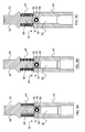
- FIGS. 1 , 1 A and 1 B there is shown a typical pneumatic operating mechanism for the plungers of a diaphragm-sealed valve.
- a typical pneumatic operating mechanism for the plungers of a diaphragm-sealed valve includes two sets of plungers, respectively designated as “normally closed and “normally opened” plungers, each set being attached to a corresponding piston.
- the actuating pneumatic pressure of each piston is set to a value sufficient to generate the required force on the corresponding plungers to seal the diaphragm between ports, without over stressing the diaphragm.
- Diaphragm-sealed valves are normally operated with the help of a three way electric solenoid valve.
- the solenoid valve When the solenoid valve is powered ON (see FIG. 2 (PRIOR ART)), the actuating pressure is applied into actuating mechanism and when the solenoid valve is powered OFF (such as shown in FIG. 1B (PRIOR ART)), the pressure is evacuated from the actuator, normally to the atmosphere.
- actuating pressure values for diaphragm-sealed valves range from 50 to 65 PSIG. If the available actuating pressure from the solenoid valve is higher, as is normally the case in a process plant environment where 125 PSIG are usually available, a pressure regulator must be use to decrease the supplied pressure to a safe level. This requires another piece of hardware and associated tubing inside the instrument, increasing the overall cost and necessitating a larger equipment inventory.
- a valve as shown in FIG. 1 When a valve as shown in FIG. 1 is actuated at a typical actuating pressure, for example 60 PSIG, and the temperature is ramped up, another problem may appear, depending on the system configuration.
- the pressurized volume inside the valve is ramped up from ambient temperature to 300° C., generating a pressure rise of about 60 PSIG. This results in a final pressure inside the system of roughly about 120 PSIG.
- This generates an uncontrolled extra force on the diaphragm that contributes to diminished valve performance over the time. Since the resulting increase in force acting on the diaphragm coincides with operating conditions where the diaphragm material is softened by the high temperature, operating under these conditions will reduce dramatically the valve performance and lifetime.
- a plunger for a diaphragm-sealed valve having a valve body provided with at least one passage extending in the valve body and opening on a diaphragm-contacting surface, a plunger-actuating mechanism being located within the valve body, said plunger being sized to slidably fit in a corresponding one of the at least one passage of the valve body and comprising:
- misalignments of the plunger relative to its corresponding passage may be compensated for by allowing the upper member of the plunger to align itself with the passage, thereby improving the overall valve performances.
- a plunger assembly for a diaphragm-sealed valve having a valve body provided with a plurality of passages extending in the valve body and opening on a diaphragm-contacting surface, said plunger assembly comprising:
- an adjustable attachment connects the base member of each plunger to the plunger-actuating mechanism, therefore allowing a fine-tuning of the distance therebetween.
- FIG. 1 (PRIOR ART) is a top view of a valve according to prior art.
- FIG. 1A is a cross-sectional view along lines A-A of FIG. 1 ;
- FIG. 1B is an enlargement of portion B of FIG. 1A , and is shown with the actuating mechanism turned “OFF”.
- FIG. 2 shows an enlargement of a cross-sectional view of the valve of FIG. 1 , shown with the actuating mechanism turned “ON”.
- FIG. 3 is a top view of a diaphragm-sealed valve provided with plungers according to embodiments of the invention.
- FIG. 4A is a cross sectional view along lines A-A the valve of FIG. 3
- FIG. 4B is an enlargement of a portion of FIG. 4A , showing a portion of a plunger assembly according to an embodiment of the present invention before actuation.
- FIG. 5A is a cross sectional view along lines A-A the valve of FIG. 3
- FIG. 5B is an enlargement of a portion of FIG. 5A , showing a portion of a plunger assembly according to an embodiment of the present invention after actuation.
- FIG. 6A is a side view of a plunger according to an embodiment of the invention
- FIG. 6B is a cross-sectional view along lines B-B of FIG. 6A
- FIG. 6C is a side view of the plunger of FIG. 6A from a perpendicular direction.
- FIGS. 7A and 7B are cross-sectional views of plungers according to variants of the embodiment of FIGS. 6A to 6C , provided with different types of resilient middle elements.
- FIG. 8A to 8C are cross-section views of plungers according to a different embodiment of the invention, shown with different types of resilient elements.
- FIG. 9 is a cross-sectional view of a plunger according to another embodiment of the invention, wherein a portion of the resilient middle element is received within a recess in the base member.
- FIGS. 10A and 10B are cross-sectional views of a plunger according to another embodiment of the invention, wherein the head member of the plunger is self-aligning.
- FIG. 11A is a top view of the normally open plunger according to an embodiment of the invention, where the upper member is removed from the base member;
- FIG. 11B is a side view of the plunger of FIG. 11A .
- FIG. 12A is a top view of the normally closed plunger according to an embodiment of the invention, where the upper member is removed from the base member;
- FIG. 12B is a side view of the plunger of FIG. 12A .
- FIG. 13A is a top view of a valve according to another embodiment of the invention
- FIG. 13B is a cross-sectional view taken along lines A-A of FIG. 13A
- FIG. 13C is an enlarged portion A of FIG. 13B showing the plungers of FIGS. 10A and 10B inside the valve.
- FIG. 14 is a top view of a plunger according to another embodiment of the invention incorporating a self-aligning head member;
- FIG. 14A is a cross-sectional view taken along lines A-A of FIG. 14 ;
- FIG. 14B is a cross-sectional view taken along lines B-B of FIG. 14 .
- FIG. 15A is a top view of a valve according to another embodiment of the invention
- FIG. 15B is a cross-sectional view taken along lines A-A of FIG. 15A
- FIG. 15C is an enlarged portion A of FIG. 15B showing the plungers of FIGS. 10A to 11C inside the valve.
- FIGS. 16A and 16B are perspective exploded views of plungers having an adjustable base section according to embodiments of the invention.
- FIG. 17 is a cross sectional view of a portion of a plunger assembly incorporating plungers according to the embodiments of FIGS. 16A and 16B .
- FIG. 18 is a cross-sectional view of a plunger according to yet another embodiment of the invention, where the upper member is not interlocked with the base member.
- FIG. 19 is a cross sectional view of a portion of a plunger assembly incorporating plungers according to the embodiment of FIG. 18 .
- FIG. 20 is a graphic of the actuating pressure required to maintain proper sealing of a typical polymer diaphragm-sealed valve.
- the present invention generally relates to plungers and plunger assemblies for diaphragm-sealed valves, for example of type suitable for gas chromatography.
- the valve 20 generally includes a valve body 22 , a valve cap 24 and a diaphragm compressibly disposed therebetween.
- a valve body 22 For more detail on the construction of a valve of this type, reference can for example be made to international patent application published under no. WO/2009/073966.
- One or more passage 28 extends in the valve body 22 and open on a diaphragm-contacting surface 30 .
- a plunger-actuating mechanism 32 is located within the valve body.
- the illustrated embodiment shows a six (6) plungers valve, two (2) of which being shown in FIGS. 4B and 5B .
- the present invention may be applied to diaphragm-sealed valves having a different number of plungers.
- the term “plunger” is understood to mean a mechanical component driven by or against a mechanical force or fluid pressure. The particular construction of plungers 34 according to embodiments of the present invention will be explained further below.
- Each plunger 34 is slideable in a corresponding passage 28 of the valve body 22 .
- the diameter of a passage 28 is slightly larger than that of its corresponding plunger 34 .
- a guide sleeve (not shown) may surround the passage 28 , for facilitating the movement of the plunger 34 into the passage 28 .
- the contact area of each plunger 34 is pushed evenly throughout its surface. Thus, all mechanic or fluid forces are transferred equally onto the diaphragm 26 . This design ensures that the plungers 34 remain substantially vertical when actuated.
- the plungers 34 are preferably of two types, designated as “normally closed” (NC) and “normally open” (NO).
- the plungers 34 of a given type are actuated together, so that they are either all in the closed position or all in the open position.
- the normally closed plungers 34 NC are biased towards the closed position
- the normally opened plungers 34 NO are biased towards the open position.
- the plunger-actuating mechanism 32 preferably includes a push plate 36 which extends within the valve body 22 in parallel to its diaphragm-contacting surface 30 , and is movable transversally thereto.
- the normally closed plungers 34 NC are mounted on the push plate 36 .
- the plunger-actuating mechanism 32 further includes an upper piston 38 extending contiguously under the push plate 36 .
- the normally open plungers 34 NO are mounted on the upper piston 38 .
- a plurality of cavities 40 extend across the push plate 36 for allowing the normally open plungers therethrough.
- the plunger-actuating mechanism 32 further includes a lower piston 42 extending contiguously under the upper piston 38 and rigidly connected to the push plate 36 .
- the lower piston 42 and push plate 36 therefore move together within the valve body 22 .
- Dowel pins may be provided to prevent the upper and lower pistons 38 and 42 from rotating with respect to each other and with respect to the valve body 22 , and O-rings 44 are preferably provided to properly seal the upper and lower pistons 38 and 42 .
- a Belleville assembly 46 including a Belleville washer stack and a plate, cooperates with the lower piston 42 .
- the force on the Belleville assembly 46 is preferably controlled by a compression set screw 48 .
- a bottom cap (not shown) may close the valve body 22 at its bottom end.
- the Belleville assembly 46 may be replaced by any other biasing means, such as standard springs or polymer bushings.
- the upper piston 38 is biased downward by appropriate means.
- disc spring 50 extend from within the valve body 22 over the upper piston 38 , and applies a downward force thereon when no opposite force is in play.
- the normally open plungers 34 NO mounted on the upper piston 38 are therefore biased towards the open position. In the upward direction, the stroke of the upper piston 38 is limited by a shoulder 52 machined in the valve body 22 .
- the actuating mechanism 32 is operable for actuating the plungers 34 of both types between their open and closed positions thereof. This can be accomplished in the current embodiment by controlling the distance between the upper and lower pistons 38 and 42 . When not actuated, as shown in FIG. 4B , the two pistons 38 and 42 are in contact, as they are pushed towards each other by the Belleville assembly 46 and disc spring 50 .
- the actuating mechanism 32 preferably includes a pneumatic actuator formed by the two pistons 38 and 42 , the push plate 36 and the Belleville assembly 46 , and further includes a solenoid valve or other appropriate system for supplying pressurised gas between the upper and lower pistons 38 and 42 through a cylinder port. When the valve is actuated (see FIG.
- the gas will counterbalance the bias of both pistons 38 and 42 by pushing the upper piston 38 upward, thus sliding the normally open plungers 34 NO towards the closed position, and then pushing the lower piston 42 downwards, thus pulling the push plate 36 downward and retracting the normally closed plungers 34 NC towards the open position. Removing the pressurized gas will have the opposite result, due to the biasing effect of the Belleville assembly 46 and disc spring 50 .
- FIGS. 6A to 6C there is shown a first embodiment of a plunger 34 according to an embodiment of the present invention.
- Each plunger is made of three (3) separate sections: a base member 60 , an upper member 62 , and a resilient middle element 64 .
- the base member 60 is operatively connected to the plunger-actuating mechanism for collaboration therewith.
- the plungers 34 are affixed to either the push plate or the upper piston through fixed fasteners such as screws, which advantageously allows the valve to be fully operational regardless of its orientation. It will therefore be understood by one skilled in the art that the reference to the directions “up” and “down” or “upper” and “lower” throughout the present application is used for ease of reference to the drawings, and is not meant to indicate a preferred orientation of the valve in use.
- the upper member 62 projects towards the diaphragm-contacting surface of the valve body, and will therefore compress the diaphragm when the plunger is in the closed position.
- the upper member 62 is interlocked with the base member 60 .
- interlocked it is understood that the upper member 62 and base member 60 are connected directly or indirectly in such a fashion that they are part of a same mechanism.
- the upper member 62 has a longitudinal play within the passage of the valve body with respect to the base member 60 , that is, it is free to move vertically up and down over an appropriate distance with respect to the base member 60 .
- the resilient middle element 64 is disposed between the base member 60 and upper member 62 .
- the resilient middle element 64 preferably biases the upper member 62 away from the base member 60 .
- the base member pulls down the upper member to clear the diaphragm.
- the upper member 62 of the plunger preferably includes a head portion 66 which projects towards the diaphragm-contacting surface, a neck portion 68 which holds the resilient middle element 64 and an anchor portion 70 interlocked with the base member 60 .
- the resilient middle element 64 is preferably ring shaped, surrounds the neck portion 68 and its opposite ends 72 a and 72 b respectively abuts on the under face of the head portion 66 and a surface of the base member defining an abutment surface 74 .
- the abutment surface of the base member extends on the top thereof.
- the anchor portion 70 of the upper member 62 has a width greater than its neck portion 68 , and may for example be shaped as a disk as shown in the drawings in reference.
- the anchor portion 70 is preferably received in a cavity 76 provided in the base member 60 , this cavity 76 being sized to provide a longitudinal clearance 78 for the anchor portion 70 .
- the upper member can move over a certain range along the longitudinal axis of the plunger 34 , thereby defining a longitudinal play between the upper and base member 62 and 60 .
- the upper member 62 and base member 60 are machined to define mating shapes as shown in the drawings.
- the base member 60 further preferably includes a bore 82 extending longitudinally therein and having opposite extremities 84 a and 84 b opening on the abutment surface 74 of the base member 60 and on the cavity 76 , respectively.
- the bore 82 is sized to receive therein a section of the neck portion 68 of the upper member 62 .
- the transition between the bore 82 and the cavity 76 defines a shoulder 86 for holding the anchor portion 70 within the cavity 76 .
- the base member 60 preferably has a slot 80 opening on a side thereof providing access to the cavity 76 for assembling the components of the plunger together.
- FIGS. 8A , 8 B and 8 C there is shown another embodiment of the invention where a retention pin 88 connects the upper member 62 to the base member 60 .
- the anchor portion is preferably an extension of the neck portion with a same cross-section, and is provided with a pin hole 90 extending therethrough for receiving the retention pin 88 .
- the base member has a pin channel 92 extending transversally therethrough, in alignment with the pin hole 90 of the upper member.
- the pin channel 92 and pin hole 90 are sized to provide a longitudinal clearance 78 for the pin 88 therein, thereby defining the longitudinal play between the upper member 62 and base member 60 .
- FIG. 9 shows yet another embodiment of the invention, wherein the base member 60 is provided with comprises a recess 96 extending longitudinally therein and opening upwardly.
- the resilient middle element 64 is received at least partially within this recess 96 , the bottom surface of which defining in this case the abutment surface 74 .
- the resilient middle element may be embodied by various resilient components, which are preferably selected in view of the particular application to which the valve is destined.
- FIGS. 6B and 8A there are shown examples of plungers where the resilient middle element is embodied by a resilient sleeve or ring made of an appropriate polymer or silicone material.
- Such an embodiment would be particularly appropriate for applications where the required sealing force is light, as for low pressure operation.
- a helicoids shape spring could be use as show in FIGS. 7A and 8B .
- the resilient middle element can consist of a washer, made for example of TeflonTM, or be composed of a plurality of components combined together, such as for example a stack of discs made of a compressible material.
- the plungers of a given valve may be easily disassembled to change the middle element and therefore adapt the valve to different pressure requirements of a given application. Alternatively, the plungers themselves may be changed or an entirely different valve may be used for different applications.
- FIGS. 10A , 10 B, 11 A, 11 B, 12 A, 12 B and 13 A to 13 C there are shown embodiments of the invention where a transversal play is provided between the upper member and base member, thereby providing for the upper member to be self-aligning within the corresponding passage.
- plungers for typical diaphragm-sealed valves With known plungers for typical diaphragm-sealed valves, slight variations coming from the manufacturing process or the assembly process may cause a plunger to be slightly slanted or misaligned relative to their respective plunger passage. Misalignments can also appear with time due to extensive use and may cause a plunger to rub or scratch the inner surface of its corresponding plunger passage, leading to a premature wear of the valve. The friction of the plunger against the inner surface of the passage may generate particles which, when accumulating on the top surface of the plunger, eventually prevent the proper closing of the ports by the plungers.
- the plungers when rubbing against the inner surface of the plunger passages, also made of stainless steel, generate particles accumulating on top of the plunger, causing variations of lengths amongst the set of plungers attached to a specific piston, which will eventually prevent the proper closing of the ports by the plungers and affect the overall functioning of the valve.
- plastic sleeves are placed around the plunger to facilitate their sliding into the plunger passages.
- the base of the plunger may also rub against the sleeved surface and generate plastic dust which may also eventually prevent the proper functioning of the valve, especially in cases where the valve has endured extensive cycling.
- the bore 82 and cavity 76 of the base member 60 are sized to provide a transversal clearance 98 for the neck portion 68 and anchor portion 70 therein, thereby defining a transversal play between the upper member 62 and base member 60 .
- This transversal play allows the upper member 62 of the plunger to move radially with respect to the base member 60 .
- the plunger 34 is misaligned or slanted relative to its corresponding plunger passage, the upper member 62 will be able to self-align in the passage since it can move both longitudinally and transversally with respect to the passage.
- the pin channel 92 and pin hole 90 are also sized to provide a transversal clearance 98 for the pin 88 therein, thereby defining a transversal play between the upper member 62 and base member 60 .
- Both the longitudinal play and transversal play provided between the base member 60 and upper member 62 need only be over a range sufficient to allow a slight relative movement between these components.
- the longitudinal clearance 78 may be as small as in the order of 0.005′′ (five-thousandths of an inch) while the transversal clearance 98 may vary between 0.002′′ and 0.0020′′.
- these measures are provided as examples only and other clearance dimensions may be used.
- plungers shown in all the illustrated embodiments discussed above have lengths corresponding to the “longer” normally opened plungers, it will be understood that a similar structure may equally be applied to normally closed plungers.
- each plunger is attached to the corresponding part of the actuating mechanism of the valve through an adjustable attachment mechanism.
- the base member 60 of the plunger has a threaded bottom portion 100 , and each support element movable within said valve body with respect to said diaphragm-contacting surface, such as for example the push plate or the upper piston in the actuating mechanisms described herein, is provided with a corresponding threaded opening 102 for receiving the threaded bottom portion of each plunger.
- the plunger shown in FIG. 16A has a shorter base section as would typically embody a NC plunger, whereas the plunger shown in FIG. 16B has a length typical of a NO plunger. Both variants are shown in a valve body in FIG. 17 , where the NC plunger is affixed to the push plate and the NO plunger is affixed to the upper piston.
- the push plate and the upper piston are provided with the above-mentioned threaded openings 102 for collaborating with a threaded bottom portion 100 of the corresponding plungers.
- Rotating the plunger therefore allows fine-tuning the position of the base member of the plunger within the passage, and adjusts the effective length of the remainder of the plunger projecting from the push plate or upper piston.
- This embodiment advantageously makes it possible to adjust the sealing force of the plungers on the diaphragm within the working compression range of the middle portion of the plungers.
- a locking set screw 104 is provided within each threaded opening 102 underneath the corresponding plunger 34 and collaborates therewith to lock and avoid any rotation of the plunger 34 while the valve is in use.
- An appropriate sealing device such as an O-ring 106 or the like, may be provided between the locking set screw 104 and the plunger 34 to avoid pneumatic actuation gas leaks through the piston.
- An appropriate sealing device such as an O-ring 106 or the like, may be provided between the locking set screw 104 and the plunger 34 to avoid pneumatic actuation gas leaks through the piston.
- the use of a plunger construction where the head portion is rotationally free with respect to the base member, such as for example shown in FIGS. 6B , 7 A, 7 B and 9 , in combination with this embodiment would offer the advantage of avoiding any twisting of the plunger when adjusting the base member within the threaded opening 102 . While the embodiments of the plungers 34 illustrated are similar to that shown in FIG. 11 a , it will be appreciated that other embodiments of the plungers 34 , including but not limited to those having transversal play, could similarly be used.
- the upper member 62 is generally “hat” shaped and is not directly interlocked with the base member 60 .
- the base member 60 and upper member 62 have opposite abutment surfaces 74 and 75 facing each other, and in abutment with the opposite ends 72 b and 72 a of the resilient middle element 64 .
- the base member 60 includes a recess 96 in which the resilient middle element 64 is at least partially received the bottom surface of the recess 96 defining the abutment surface 74 of the base member 60 .
- the plunger 34 is preferably used in combination with a spring element 108 insertable in the passage with the plunger 34 to bias the upper member 62 away from the diaphragm-contacting surface.
- FIG. 19 shows a portion of a plunger assembly incorporating plungers 34 and spring elements 108 according to this embodiment.
- the spring element 108 may be embodied by any biasing means apt to bias the upper member 62 away from the diaphragm when the plunger 34 is retracted towards the opened position.
- the strokes of both the upper and lower pistons are limited by a shoulder in the valve body.
- an increase in actuating pressure will not move the pistons further than their predetermined stroke and will not change the force applied to the plungers.
- the stroke of each piston is such as they will compress the middle section of the respective plungers to the “tune value” without having the plunger base section forcing against the upper plunger section.
- plungers according to embodiments of the invention may mitigate or eliminate altogether the tight requirements for plunger lengths in prior art valves. It may also allow for a greater tolerance for variations in diaphragm thickness.
- the biasing force applied by the middle compressible section force varies as a function of the ambient temperature, thereby constituting an active temperature mechanical feedback loop built-in into the valve mechanism.
- FIG. 20 shows an example of the measured decrease in pneumatic actuating pressure required to maintain proper sealing between ports of a typical diaphragm-sealed valve when the operating temperature is increased.
- less force is required due to the fact that the polymer base diaphragm is softer at higher temperature. Under this operating condition, it is easy to deform it, and furthermore the diaphragm show better sealing properties at higher temperature. This is because its surfaces is less ductile and fills more the surface finish of the valve head.
- temperature characteristics of the plunger's resilient middle element are therefore selected in accordance with the temperature characteristics of the diaphragm. As different types of diaphragm material and thickness can be use, different compensation material characteristic could also be use.
- the resilient middle element of the plungers define a thermal feedback loop.
- the system could be made to decrease, increase or maintain constant the force applied on the diaphragm when the temperatures rise.
- misalignments of the plunger relative to its corresponding passage may be compensated for by allowing the upper member of the plunger to align itself with the passage.
- this self-alignment can improve the overall valve performance by reducing the friction of the plunger against the inner surface of the passage, which in turn can reduce plunger wear and the subsequent generation and accumulation of particles within the system.
- the pistons could be move by other means than pneumatic. Electrical mean such as solenoid or motor could also be considered.
- the Belleville springs mounted in the bottom of the valve body are not used to set the normally close plungers force as with prior art valve, but to set the pressure value at which the normally close ports will open, since the sealing force is fix by the compressible middle section of the plungers. This characteristic make a big difference compare to prior art. Indeed, depend on N.C. Piston Belleville washer compressibility factor, the valve actuation pressure could be adjusted, and the time that all plungers are up (to avoid various flowpath mixing upon actuation) is also adjustable. This is another benefit of the pneumatic base actuator of the embodiments described above.
Landscapes
- Engineering & Computer Science (AREA)
- General Engineering & Computer Science (AREA)
- Mechanical Engineering (AREA)
- General Health & Medical Sciences (AREA)
- Analytical Chemistry (AREA)
- Biochemistry (AREA)
- Physics & Mathematics (AREA)
- General Physics & Mathematics (AREA)
- Immunology (AREA)
- Pathology (AREA)
- Chemical & Material Sciences (AREA)
- Life Sciences & Earth Sciences (AREA)
- Health & Medical Sciences (AREA)
- Fluid-Driven Valves (AREA)
- Multiple-Way Valves (AREA)
Abstract
Description
-
- a base member operatively connectable to the actuating mechanism;
- an upper member projecting towards said diaphragm-contacting surface when in said passage, said upper member having a transversal play within said passage with respect to the base member; and
- a resilient middle element provided between the base member and the upper member.
-
- a plunger-actuating mechanism located within the valve body; and
- a plurality of plungers each slidably provided in a corresponding one of the passage of the valve body, each plunger comprising:
- a base member operatively connected to the actuating mechanism;
- an upper member projecting towards said diaphragm-contacting surface when in said passage, said upper member having a transversal play within said passage with respect to the base member; and
- a resilient middle element provided between the base member and the upper member.
Claims (15)
Priority Applications (1)
| Application Number | Priority Date | Filing Date | Title |
|---|---|---|---|
| US13/256,381 US8851452B2 (en) | 2009-04-01 | 2009-09-08 | Self-aligned plunger for chromatographic valve |
Applications Claiming Priority (3)
| Application Number | Priority Date | Filing Date | Title |
|---|---|---|---|
| US16573509P | 2009-04-01 | 2009-04-01 | |
| US13/256,381 US8851452B2 (en) | 2009-04-01 | 2009-09-08 | Self-aligned plunger for chromatographic valve |
| PCT/CA2009/001250 WO2010025570A1 (en) | 2008-09-08 | 2009-09-08 | Temperature compensated valve for gas chromatography |
Publications (2)
| Publication Number | Publication Date |
|---|---|
| US20120025120A1 US20120025120A1 (en) | 2012-02-02 |
| US8851452B2 true US8851452B2 (en) | 2014-10-07 |
Family
ID=42827446
Family Applications (1)
| Application Number | Title | Priority Date | Filing Date |
|---|---|---|---|
| US13/256,381 Active 2030-01-10 US8851452B2 (en) | 2009-04-01 | 2009-09-08 | Self-aligned plunger for chromatographic valve |
Country Status (2)
| Country | Link |
|---|---|
| US (1) | US8851452B2 (en) |
| WO (1) | WO2010111791A1 (en) |
Cited By (5)
| Publication number | Priority date | Publication date | Assignee | Title |
|---|---|---|---|---|
| US20140260538A1 (en) * | 2013-03-14 | 2014-09-18 | Rosemount Analytical Inc. | Fittingless pneumatic multiport selector valve for analytic instruments |
| US20160025688A1 (en) * | 2013-03-11 | 2016-01-28 | Mecanique Analytique Inc. | Diaphragm Valve with Sealing Assembly, Chromatographic System Including Same and Method of Operation Thereof |
| WO2019144228A1 (en) * | 2018-01-23 | 2019-08-01 | Ldetek Inc. | Valve assembly for a gas chromatograph |
| RU2785697C1 (en) * | 2022-02-08 | 2022-12-12 | Акционерное общество "Научно-производственное объединение "НЭМП" | Multi-port valve for switching, dosing and moving small flows and quantities of liquid |
| US20230028446A1 (en) * | 2019-12-18 | 2023-01-26 | Mécanique Analytique Inc. | Pulsing Purge Diaphragm Valve and Related Method |
Families Citing this family (2)
| Publication number | Priority date | Publication date | Assignee | Title |
|---|---|---|---|---|
| WO2013120208A1 (en) * | 2012-02-16 | 2013-08-22 | Mécanique Analytique Inc. | Diaphragm-sealed valve with improved actuator design |
| JP7411689B2 (en) * | 2019-02-07 | 2024-01-11 | エイ・ピィ・エヌ・インコーポレイテッド | Sample injection diaphragm valve, plunger assembly for the sample injection diaphragm valve and method of operating the sample injection diaphragm valve |
Citations (28)
| Publication number | Priority date | Publication date | Assignee | Title |
|---|---|---|---|---|
| US1710055A (en) * | 1928-02-13 | 1929-04-23 | Patrick M Grant | Fluid-pressure-operated valve |
| US1765027A (en) * | 1927-03-08 | 1930-06-17 | Edison Storage Battery Co | Storage-battery cell |
| US2615465A (en) * | 1949-03-21 | 1952-10-28 | Woodward Erwin | Self-cleaning valve |
| US3111849A (en) | 1961-03-20 | 1963-11-26 | Phillips Petroleum Co | Pneumatic amplifier sampling valve for chromatographic analyzers |
| US3140615A (en) | 1962-10-25 | 1964-07-14 | Phillips Petroleum Co | Pneumatic amplifier sampling valve for chromatographic analyzers |
| US3198018A (en) | 1961-12-28 | 1965-08-03 | Phillips Petroleum Co | Electrically actuated sampling valve |
| US3376894A (en) | 1965-05-06 | 1968-04-09 | Phillips Petroleum Co | Valve |
| US3387496A (en) | 1966-06-20 | 1968-06-11 | Phillips Petroleum Co | Pneumatic amplifier sampling valve for chromatographic analyzers |
| US3417605A (en) | 1966-10-17 | 1968-12-24 | Phillips Petroleum Co | Valve sampling system for taking gaseous samples at about atmospheric pressure |
| US3439542A (en) | 1966-06-20 | 1969-04-22 | Phillips Petroleum Co | Pneumatic amplifier sampling valve for chromatographic analyzers |
| US3492873A (en) | 1967-12-29 | 1970-02-03 | Phillips Petroleum Co | Pneumatic amplifier sampling valve for chromatographic analyzers |
| US3545491A (en) | 1969-02-05 | 1970-12-08 | Phillips Petroleum Co | Chromatographic analyzer sample valve |
| US3613729A (en) * | 1970-02-16 | 1971-10-19 | Packard Instrument Co Inc | Valve system |
| US3633426A (en) | 1970-08-10 | 1972-01-11 | Phillips Petroleum Co | Chromatographic analyzer sample valve |
| US3671009A (en) | 1969-04-15 | 1972-06-20 | Lucifer Sa | Fluid-controlling valve |
| US4112766A (en) | 1977-01-21 | 1978-09-12 | Phillips Petroleum Company | Fluid actuated valve |
| US4276907A (en) | 1979-11-21 | 1981-07-07 | Phillips Petroleum Company | Fluid actuated valve |
| US4333500A (en) | 1980-05-23 | 1982-06-08 | Phillips Petroleum Company | Fluid actuated valve |
| US4372333A (en) * | 1981-08-24 | 1983-02-08 | Baker Cac, Inc. | Valve actuating apparatus and method |
| US4474889A (en) * | 1982-04-26 | 1984-10-02 | Microsensor Technology Inc. | Miniature gas chromatograph apparatus |
| US4682757A (en) | 1986-07-18 | 1987-07-28 | Joy Manufacturing Company | Secondary backseat for gate valve |
| US5601115A (en) | 1995-05-31 | 1997-02-11 | Vantege Technologies, Inc. | Multiport sampling valve |
| US6202698B1 (en) | 1997-06-18 | 2001-03-20 | Valco Instruments Company, Inc. | Multiple port diaphragm valve |
| JP2004255431A (en) | 2003-02-27 | 2004-09-16 | Asahi-Seiki Mfg Co Ltd | Knockout device of press machine |
| US6896239B1 (en) | 2003-04-22 | 2005-05-24 | Arthur J. Brenes | Method and apparatus for locking a valve |
| US7216528B2 (en) | 2005-02-22 | 2007-05-15 | Mecanique Analytique Inc. | Diaphragm-sealed valve, analytical chromatographic system and method using the same |
| US7537194B2 (en) | 2006-06-29 | 2009-05-26 | Ckd Corporation | Flow control valve |
| US7931043B2 (en) | 2007-12-12 | 2011-04-26 | Mécanique Analytique Inc. | Diaphragm-sealed valve with process purging groove |
-
2009
- 2009-09-08 US US13/256,381 patent/US8851452B2/en active Active
-
2010
- 2010-04-01 WO PCT/CA2010/000513 patent/WO2010111791A1/en active Application Filing
Patent Citations (28)
| Publication number | Priority date | Publication date | Assignee | Title |
|---|---|---|---|---|
| US1765027A (en) * | 1927-03-08 | 1930-06-17 | Edison Storage Battery Co | Storage-battery cell |
| US1710055A (en) * | 1928-02-13 | 1929-04-23 | Patrick M Grant | Fluid-pressure-operated valve |
| US2615465A (en) * | 1949-03-21 | 1952-10-28 | Woodward Erwin | Self-cleaning valve |
| US3111849A (en) | 1961-03-20 | 1963-11-26 | Phillips Petroleum Co | Pneumatic amplifier sampling valve for chromatographic analyzers |
| US3198018A (en) | 1961-12-28 | 1965-08-03 | Phillips Petroleum Co | Electrically actuated sampling valve |
| US3140615A (en) | 1962-10-25 | 1964-07-14 | Phillips Petroleum Co | Pneumatic amplifier sampling valve for chromatographic analyzers |
| US3376894A (en) | 1965-05-06 | 1968-04-09 | Phillips Petroleum Co | Valve |
| US3387496A (en) | 1966-06-20 | 1968-06-11 | Phillips Petroleum Co | Pneumatic amplifier sampling valve for chromatographic analyzers |
| US3439542A (en) | 1966-06-20 | 1969-04-22 | Phillips Petroleum Co | Pneumatic amplifier sampling valve for chromatographic analyzers |
| US3417605A (en) | 1966-10-17 | 1968-12-24 | Phillips Petroleum Co | Valve sampling system for taking gaseous samples at about atmospheric pressure |
| US3492873A (en) | 1967-12-29 | 1970-02-03 | Phillips Petroleum Co | Pneumatic amplifier sampling valve for chromatographic analyzers |
| US3545491A (en) | 1969-02-05 | 1970-12-08 | Phillips Petroleum Co | Chromatographic analyzer sample valve |
| US3671009A (en) | 1969-04-15 | 1972-06-20 | Lucifer Sa | Fluid-controlling valve |
| US3613729A (en) * | 1970-02-16 | 1971-10-19 | Packard Instrument Co Inc | Valve system |
| US3633426A (en) | 1970-08-10 | 1972-01-11 | Phillips Petroleum Co | Chromatographic analyzer sample valve |
| US4112766A (en) | 1977-01-21 | 1978-09-12 | Phillips Petroleum Company | Fluid actuated valve |
| US4276907A (en) | 1979-11-21 | 1981-07-07 | Phillips Petroleum Company | Fluid actuated valve |
| US4333500A (en) | 1980-05-23 | 1982-06-08 | Phillips Petroleum Company | Fluid actuated valve |
| US4372333A (en) * | 1981-08-24 | 1983-02-08 | Baker Cac, Inc. | Valve actuating apparatus and method |
| US4474889A (en) * | 1982-04-26 | 1984-10-02 | Microsensor Technology Inc. | Miniature gas chromatograph apparatus |
| US4682757A (en) | 1986-07-18 | 1987-07-28 | Joy Manufacturing Company | Secondary backseat for gate valve |
| US5601115A (en) | 1995-05-31 | 1997-02-11 | Vantege Technologies, Inc. | Multiport sampling valve |
| US6202698B1 (en) | 1997-06-18 | 2001-03-20 | Valco Instruments Company, Inc. | Multiple port diaphragm valve |
| JP2004255431A (en) | 2003-02-27 | 2004-09-16 | Asahi-Seiki Mfg Co Ltd | Knockout device of press machine |
| US6896239B1 (en) | 2003-04-22 | 2005-05-24 | Arthur J. Brenes | Method and apparatus for locking a valve |
| US7216528B2 (en) | 2005-02-22 | 2007-05-15 | Mecanique Analytique Inc. | Diaphragm-sealed valve, analytical chromatographic system and method using the same |
| US7537194B2 (en) | 2006-06-29 | 2009-05-26 | Ckd Corporation | Flow control valve |
| US7931043B2 (en) | 2007-12-12 | 2011-04-26 | Mécanique Analytique Inc. | Diaphragm-sealed valve with process purging groove |
Non-Patent Citations (1)
| Title |
|---|
| International Search Report, Dec. 7, 2010. |
Cited By (9)
| Publication number | Priority date | Publication date | Assignee | Title |
|---|---|---|---|---|
| US20160025688A1 (en) * | 2013-03-11 | 2016-01-28 | Mecanique Analytique Inc. | Diaphragm Valve with Sealing Assembly, Chromatographic System Including Same and Method of Operation Thereof |
| US9632065B2 (en) * | 2013-03-11 | 2017-04-25 | Mécanique Analytique Inc. | Diaphragm valve with sealing assembly, chromatographic system including same and method of operation thereof |
| US20140260538A1 (en) * | 2013-03-14 | 2014-09-18 | Rosemount Analytical Inc. | Fittingless pneumatic multiport selector valve for analytic instruments |
| US9249890B2 (en) * | 2013-03-14 | 2016-02-02 | Rosemount Analytical Inc. | Fittingless pneumatic multiport selector valve for analytic instruments |
| WO2019144228A1 (en) * | 2018-01-23 | 2019-08-01 | Ldetek Inc. | Valve assembly for a gas chromatograph |
| US11448623B2 (en) | 2018-01-23 | 2022-09-20 | Ldetek Inc. | Valve assembly for a gas chromatograph |
| US20230028446A1 (en) * | 2019-12-18 | 2023-01-26 | Mécanique Analytique Inc. | Pulsing Purge Diaphragm Valve and Related Method |
| US11788994B2 (en) * | 2019-12-18 | 2023-10-17 | Mécanique Analytique Inc. | Pulsing purge diaphragm valve and related method |
| RU2785697C1 (en) * | 2022-02-08 | 2022-12-12 | Акционерное общество "Научно-производственное объединение "НЭМП" | Multi-port valve for switching, dosing and moving small flows and quantities of liquid |
Also Published As
| Publication number | Publication date |
|---|---|
| US20120025120A1 (en) | 2012-02-02 |
| WO2010111791A1 (en) | 2010-10-07 |
Similar Documents
| Publication | Publication Date | Title |
|---|---|---|
| US8851452B2 (en) | Self-aligned plunger for chromatographic valve | |
| US8794594B2 (en) | Temperature compensated valve for gas chromatography | |
| US10428960B2 (en) | Valve with a load varying mechanism, and method of operating the same | |
| KR100845160B1 (en) | Vacuum valve | |
| US8104506B2 (en) | Diaphragm-sealed valve having intermediate communication ports | |
| US7931043B2 (en) | Diaphragm-sealed valve with process purging groove | |
| US9377444B2 (en) | Diaphragm-sealed valve with improved actuator design | |
| CA3125342C (en) | Sample injection diaphragm valve | |
| RU2583488C2 (en) | Guide device for drive rod for use with drives of hydraulic valve | |
| KR102276928B1 (en) | electronic expansion valve | |
| US8608127B2 (en) | Piezoelectric proportional control valve | |
| CN114867973B (en) | Expansion valve | |
| US20240044848A1 (en) | Variable load chromatography valve for fluid analysis | |
| KR20100116737A (en) | Displacement control valve of variable displacement compressor |
Legal Events
| Date | Code | Title | Description |
|---|---|---|---|
| AS | Assignment |
Owner name: MECANIQUE ANALYTIQUE INC., CANADA Free format text: ASSIGNMENT OF ASSIGNORS INTEREST;ASSIGNORS:GAMACHE, YVES;FORTIER, ANDRE;REEL/FRAME:027141/0965 Effective date: 20101125 |
|
| STCF | Information on status: patent grant |
Free format text: PATENTED CASE |
|
| CC | Certificate of correction | ||
| AS | Assignment |
Owner name: APN-AFP INC., CANADA Free format text: ASSIGNMENT OF ASSIGNORS INTEREST;ASSIGNOR:MECANIQUE ANALYTIQUE INC.;REEL/FRAME:042852/0513 Effective date: 20170531 |
|
| MAFP | Maintenance fee payment |
Free format text: PAYMENT OF MAINTENANCE FEE, 4TH YEAR, LARGE ENTITY (ORIGINAL EVENT CODE: M1551) Year of fee payment: 4 |
|
| AS | Assignment |
Owner name: APN INC., CANADA Free format text: ASSIGNMENT OF ASSIGNORS INTEREST;ASSIGNOR:APN AFP INC.;REEL/FRAME:056722/0131 Effective date: 20210621 |
|
| AS | Assignment |
Owner name: NATIONAL BANK OF CANADA, CANADA Free format text: SECURITY INTEREST;ASSIGNORS:APN INC.;APN MONDIAL INC.;REEL/FRAME:057994/0028 Effective date: 20210722 |
|
| MAFP | Maintenance fee payment |
Free format text: PAYMENT OF MAINTENANCE FEE, 8TH YEAR, LARGE ENTITY (ORIGINAL EVENT CODE: M1552); ENTITY STATUS OF PATENT OWNER: LARGE ENTITY Year of fee payment: 8 |
|
| AS | Assignment |
Owner name: APN INC., CANADA Free format text: RELEASE BY SECURED PARTY;ASSIGNOR:NATIONAL BANK OF CANADA;REEL/FRAME:061956/0965 Effective date: 20221107 Owner name: APN MONDIAL INC., CANADA Free format text: RELEASE BY SECURED PARTY;ASSIGNOR:NATIONAL BANK OF CANADA;REEL/FRAME:061956/0965 Effective date: 20221107 |