JP6100373B2 - Method for forming a continuous dielectric film containing dispersed nanoparticles - Google Patents
Method for forming a continuous dielectric film containing dispersed nanoparticles Download PDFInfo
- Publication number
- JP6100373B2 JP6100373B2 JP2015521056A JP2015521056A JP6100373B2 JP 6100373 B2 JP6100373 B2 JP 6100373B2 JP 2015521056 A JP2015521056 A JP 2015521056A JP 2015521056 A JP2015521056 A JP 2015521056A JP 6100373 B2 JP6100373 B2 JP 6100373B2
- Authority
- JP
- Japan
- Prior art keywords
- nanoparticles
- secondary feed
- dielectric film
- liquid carrier
- dielectric
- Prior art date
- Legal status (The legal status is an assumption and is not a legal conclusion. Google has not performed a legal analysis and makes no representation as to the accuracy of the status listed.)
- Active
Links
- 239000002105 nanoparticle Substances 0.000 title claims description 30
- 238000000034 method Methods 0.000 title claims description 25
- 239000007788 liquid Substances 0.000 claims description 10
- 239000002114 nanocomposite Substances 0.000 claims description 9
- 239000013078 crystal Substances 0.000 claims description 7
- 229920001169 thermoplastic Polymers 0.000 claims description 7
- 239000004416 thermosoftening plastic Substances 0.000 claims description 7
- XEKOWRVHYACXOJ-UHFFFAOYSA-N Ethyl acetate Chemical group CCOC(C)=O XEKOWRVHYACXOJ-UHFFFAOYSA-N 0.000 claims description 6
- GWEVSGVZZGPLCZ-UHFFFAOYSA-N Titan oxide Chemical compound O=[Ti]=O GWEVSGVZZGPLCZ-UHFFFAOYSA-N 0.000 claims description 6
- YXFVVABEGXRONW-UHFFFAOYSA-N Toluene Natural products CC1=CC=CC=C1 YXFVVABEGXRONW-UHFFFAOYSA-N 0.000 claims description 5
- 238000002156 mixing Methods 0.000 claims description 4
- 229910052709 silver Inorganic materials 0.000 claims description 4
- 239000004332 silver Substances 0.000 claims description 4
- 239000008187 granular material Substances 0.000 claims description 3
- 239000004408 titanium dioxide Substances 0.000 claims description 2
- 125000003944 tolyl group Chemical group 0.000 claims 1
- 239000002245 particle Substances 0.000 description 21
- 229920000642 polymer Polymers 0.000 description 20
- 239000004793 Polystyrene Substances 0.000 description 10
- 239000003990 capacitor Substances 0.000 description 10
- 239000000463 material Substances 0.000 description 10
- 229920002223 polystyrene Polymers 0.000 description 10
- 230000008569 process Effects 0.000 description 9
- 239000003989 dielectric material Substances 0.000 description 8
- 230000005684 electric field Effects 0.000 description 6
- 239000000203 mixture Substances 0.000 description 5
- -1 polyethylene terephthalate Polymers 0.000 description 5
- 239000004743 Polypropylene Substances 0.000 description 4
- 230000008901 benefit Effects 0.000 description 4
- 238000001816 cooling Methods 0.000 description 4
- 239000006185 dispersion Substances 0.000 description 4
- 238000004146 energy storage Methods 0.000 description 4
- 238000001125 extrusion Methods 0.000 description 4
- 239000012467 final product Substances 0.000 description 4
- 238000002347 injection Methods 0.000 description 4
- 239000007924 injection Substances 0.000 description 4
- 239000011159 matrix material Substances 0.000 description 4
- 230000007246 mechanism Effects 0.000 description 4
- 239000012528 membrane Substances 0.000 description 4
- 230000002572 peristaltic effect Effects 0.000 description 4
- 229920000139 polyethylene terephthalate Polymers 0.000 description 4
- 239000005020 polyethylene terephthalate Substances 0.000 description 4
- 229920001155 polypropylene Polymers 0.000 description 4
- BQCADISMDOOEFD-UHFFFAOYSA-N Silver Chemical compound [Ag] BQCADISMDOOEFD-UHFFFAOYSA-N 0.000 description 3
- 230000015556 catabolic process Effects 0.000 description 3
- 239000000919 ceramic Substances 0.000 description 3
- 239000002131 composite material Substances 0.000 description 3
- 238000009826 distribution Methods 0.000 description 3
- 238000005516 engineering process Methods 0.000 description 3
- 239000004033 plastic Substances 0.000 description 3
- 229920003023 plastic Polymers 0.000 description 3
- 238000000527 sonication Methods 0.000 description 3
- 239000000758 substrate Substances 0.000 description 3
- 229920005601 base polymer Polymers 0.000 description 2
- 238000002425 crystallisation Methods 0.000 description 2
- 230000008025 crystallization Effects 0.000 description 2
- 230000007547 defect Effects 0.000 description 2
- 238000006731 degradation reaction Methods 0.000 description 2
- 230000000694 effects Effects 0.000 description 2
- 238000001704 evaporation Methods 0.000 description 2
- 230000008020 evaporation Effects 0.000 description 2
- 229910044991 metal oxide Inorganic materials 0.000 description 2
- 150000004706 metal oxides Chemical class 0.000 description 2
- 238000002203 pretreatment Methods 0.000 description 2
- 238000003672 processing method Methods 0.000 description 2
- 239000000047 product Substances 0.000 description 2
- 238000000926 separation method Methods 0.000 description 2
- 229920001187 thermosetting polymer Polymers 0.000 description 2
- 230000007704 transition Effects 0.000 description 2
- 239000004594 Masterbatch (MB) Substances 0.000 description 1
- 239000004698 Polyethylene Substances 0.000 description 1
- BLRPTPMANUNPDV-UHFFFAOYSA-N Silane Chemical compound [SiH4] BLRPTPMANUNPDV-UHFFFAOYSA-N 0.000 description 1
- 230000006750 UV protection Effects 0.000 description 1
- 238000005054 agglomeration Methods 0.000 description 1
- 230000002776 aggregation Effects 0.000 description 1
- 229910052782 aluminium Inorganic materials 0.000 description 1
- XAGFODPZIPBFFR-UHFFFAOYSA-N aluminium Chemical compound [Al] XAGFODPZIPBFFR-UHFFFAOYSA-N 0.000 description 1
- 238000013459 approach Methods 0.000 description 1
- 238000010923 batch production Methods 0.000 description 1
- 238000005266 casting Methods 0.000 description 1
- 230000003197 catalytic effect Effects 0.000 description 1
- 238000004140 cleaning Methods 0.000 description 1
- 238000010790 dilution Methods 0.000 description 1
- 239000012895 dilution Substances 0.000 description 1
- 238000004090 dissolution Methods 0.000 description 1
- 239000010419 fine particle Substances 0.000 description 1
- 239000011888 foil Substances 0.000 description 1
- 238000009472 formulation Methods 0.000 description 1
- 238000010438 heat treatment Methods 0.000 description 1
- 239000012535 impurity Substances 0.000 description 1
- 238000011065 in-situ storage Methods 0.000 description 1
- 238000010348 incorporation Methods 0.000 description 1
- 230000006698 induction Effects 0.000 description 1
- 239000011810 insulating material Substances 0.000 description 1
- 150000002500 ions Chemical class 0.000 description 1
- 238000004519 manufacturing process Methods 0.000 description 1
- 229910052751 metal Inorganic materials 0.000 description 1
- 239000002184 metal Substances 0.000 description 1
- 229910052755 nonmetal Inorganic materials 0.000 description 1
- 229920000052 poly(p-xylylene) Polymers 0.000 description 1
- 239000004417 polycarbonate Substances 0.000 description 1
- 229920000515 polycarbonate Polymers 0.000 description 1
- 229920000573 polyethylene Polymers 0.000 description 1
- 238000003303 reheating Methods 0.000 description 1
- 238000005096 rolling process Methods 0.000 description 1
- 239000000523 sample Substances 0.000 description 1
- 229910000077 silane Inorganic materials 0.000 description 1
- 230000006641 stabilisation Effects 0.000 description 1
- 238000011105 stabilization Methods 0.000 description 1
- 238000004381 surface treatment Methods 0.000 description 1
- 239000004094 surface-active agent Substances 0.000 description 1
- 239000012815 thermoplastic material Substances 0.000 description 1
- 239000004634 thermosetting polymer Substances 0.000 description 1
- 238000011282 treatment Methods 0.000 description 1
- 238000002604 ultrasonography Methods 0.000 description 1
Images


Classifications
-
- C—CHEMISTRY; METALLURGY
- C08—ORGANIC MACROMOLECULAR COMPOUNDS; THEIR PREPARATION OR CHEMICAL WORKING-UP; COMPOSITIONS BASED THEREON
- C08J—WORKING-UP; GENERAL PROCESSES OF COMPOUNDING; AFTER-TREATMENT NOT COVERED BY SUBCLASSES C08B, C08C, C08F, C08G or C08H
- C08J5/00—Manufacture of articles or shaped materials containing macromolecular substances
- C08J5/18—Manufacture of films or sheets
-
- B—PERFORMING OPERATIONS; TRANSPORTING
- B29—WORKING OF PLASTICS; WORKING OF SUBSTANCES IN A PLASTIC STATE IN GENERAL
- B29C—SHAPING OR JOINING OF PLASTICS; SHAPING OF MATERIAL IN A PLASTIC STATE, NOT OTHERWISE PROVIDED FOR; AFTER-TREATMENT OF THE SHAPED PRODUCTS, e.g. REPAIRING
- B29C48/00—Extrusion moulding, i.e. expressing the moulding material through a die or nozzle which imparts the desired form; Apparatus therefor
- B29C48/14—Extrusion moulding, i.e. expressing the moulding material through a die or nozzle which imparts the desired form; Apparatus therefor characterised by the particular extruding conditions, e.g. in a modified atmosphere or by using vibration
- B29C48/142—Extrusion moulding, i.e. expressing the moulding material through a die or nozzle which imparts the desired form; Apparatus therefor characterised by the particular extruding conditions, e.g. in a modified atmosphere or by using vibration using force fields, e.g. gravity or electrical fields
-
- B—PERFORMING OPERATIONS; TRANSPORTING
- B29—WORKING OF PLASTICS; WORKING OF SUBSTANCES IN A PLASTIC STATE IN GENERAL
- B29C—SHAPING OR JOINING OF PLASTICS; SHAPING OF MATERIAL IN A PLASTIC STATE, NOT OTHERWISE PROVIDED FOR; AFTER-TREATMENT OF THE SHAPED PRODUCTS, e.g. REPAIRING
- B29C48/00—Extrusion moulding, i.e. expressing the moulding material through a die or nozzle which imparts the desired form; Apparatus therefor
- B29C48/022—Extrusion moulding, i.e. expressing the moulding material through a die or nozzle which imparts the desired form; Apparatus therefor characterised by the choice of material
-
- B—PERFORMING OPERATIONS; TRANSPORTING
- B29—WORKING OF PLASTICS; WORKING OF SUBSTANCES IN A PLASTIC STATE IN GENERAL
- B29C—SHAPING OR JOINING OF PLASTICS; SHAPING OF MATERIAL IN A PLASTIC STATE, NOT OTHERWISE PROVIDED FOR; AFTER-TREATMENT OF THE SHAPED PRODUCTS, e.g. REPAIRING
- B29C48/00—Extrusion moulding, i.e. expressing the moulding material through a die or nozzle which imparts the desired form; Apparatus therefor
- B29C48/03—Extrusion moulding, i.e. expressing the moulding material through a die or nozzle which imparts the desired form; Apparatus therefor characterised by the shape of the extruded material at extrusion
- B29C48/07—Flat, e.g. panels
- B29C48/08—Flat, e.g. panels flexible, e.g. films
-
- B—PERFORMING OPERATIONS; TRANSPORTING
- B29—WORKING OF PLASTICS; WORKING OF SUBSTANCES IN A PLASTIC STATE IN GENERAL
- B29C—SHAPING OR JOINING OF PLASTICS; SHAPING OF MATERIAL IN A PLASTIC STATE, NOT OTHERWISE PROVIDED FOR; AFTER-TREATMENT OF THE SHAPED PRODUCTS, e.g. REPAIRING
- B29C48/00—Extrusion moulding, i.e. expressing the moulding material through a die or nozzle which imparts the desired form; Apparatus therefor
- B29C48/16—Articles comprising two or more components, e.g. co-extruded layers
-
- B—PERFORMING OPERATIONS; TRANSPORTING
- B29—WORKING OF PLASTICS; WORKING OF SUBSTANCES IN A PLASTIC STATE IN GENERAL
- B29C—SHAPING OR JOINING OF PLASTICS; SHAPING OF MATERIAL IN A PLASTIC STATE, NOT OTHERWISE PROVIDED FOR; AFTER-TREATMENT OF THE SHAPED PRODUCTS, e.g. REPAIRING
- B29C48/00—Extrusion moulding, i.e. expressing the moulding material through a die or nozzle which imparts the desired form; Apparatus therefor
- B29C48/25—Component parts, details or accessories; Auxiliary operations
- B29C48/285—Feeding the extrusion material to the extruder
- B29C48/287—Raw material pre-treatment while feeding
-
- B—PERFORMING OPERATIONS; TRANSPORTING
- B29—WORKING OF PLASTICS; WORKING OF SUBSTANCES IN A PLASTIC STATE IN GENERAL
- B29C—SHAPING OR JOINING OF PLASTICS; SHAPING OF MATERIAL IN A PLASTIC STATE, NOT OTHERWISE PROVIDED FOR; AFTER-TREATMENT OF THE SHAPED PRODUCTS, e.g. REPAIRING
- B29C48/00—Extrusion moulding, i.e. expressing the moulding material through a die or nozzle which imparts the desired form; Apparatus therefor
- B29C48/25—Component parts, details or accessories; Auxiliary operations
- B29C48/285—Feeding the extrusion material to the extruder
- B29C48/288—Feeding the extrusion material to the extruder in solid form, e.g. powder or granules
-
- B—PERFORMING OPERATIONS; TRANSPORTING
- B29—WORKING OF PLASTICS; WORKING OF SUBSTANCES IN A PLASTIC STATE IN GENERAL
- B29C—SHAPING OR JOINING OF PLASTICS; SHAPING OF MATERIAL IN A PLASTIC STATE, NOT OTHERWISE PROVIDED FOR; AFTER-TREATMENT OF THE SHAPED PRODUCTS, e.g. REPAIRING
- B29C48/00—Extrusion moulding, i.e. expressing the moulding material through a die or nozzle which imparts the desired form; Apparatus therefor
- B29C48/25—Component parts, details or accessories; Auxiliary operations
- B29C48/88—Thermal treatment of the stream of extruded material, e.g. cooling
- B29C48/911—Cooling
- B29C48/9135—Cooling of flat articles, e.g. using specially adapted supporting means
- B29C48/914—Cooling of flat articles, e.g. using specially adapted supporting means cooling drums
-
- C—CHEMISTRY; METALLURGY
- C08—ORGANIC MACROMOLECULAR COMPOUNDS; THEIR PREPARATION OR CHEMICAL WORKING-UP; COMPOSITIONS BASED THEREON
- C08K—Use of inorganic or non-macromolecular organic substances as compounding ingredients
- C08K3/00—Use of inorganic substances as compounding ingredients
- C08K3/02—Elements
- C08K3/08—Metals
-
- C—CHEMISTRY; METALLURGY
- C08—ORGANIC MACROMOLECULAR COMPOUNDS; THEIR PREPARATION OR CHEMICAL WORKING-UP; COMPOSITIONS BASED THEREON
- C08K—Use of inorganic or non-macromolecular organic substances as compounding ingredients
- C08K3/00—Use of inorganic substances as compounding ingredients
- C08K3/18—Oxygen-containing compounds, e.g. metal carbonyls
- C08K3/20—Oxides; Hydroxides
- C08K3/22—Oxides; Hydroxides of metals
-
- H—ELECTRICITY
- H01—ELECTRIC ELEMENTS
- H01G—CAPACITORS; CAPACITORS, RECTIFIERS, DETECTORS, SWITCHING DEVICES OR LIGHT-SENSITIVE DEVICES, OF THE ELECTROLYTIC TYPE
- H01G4/00—Fixed capacitors; Processes of their manufacture
- H01G4/002—Details
- H01G4/018—Dielectrics
- H01G4/06—Solid dielectrics
- H01G4/14—Organic dielectrics
- H01G4/18—Organic dielectrics of synthetic material, e.g. derivatives of cellulose
-
- H—ELECTRICITY
- H01—ELECTRIC ELEMENTS
- H01G—CAPACITORS; CAPACITORS, RECTIFIERS, DETECTORS, SWITCHING DEVICES OR LIGHT-SENSITIVE DEVICES, OF THE ELECTROLYTIC TYPE
- H01G4/00—Fixed capacitors; Processes of their manufacture
- H01G4/002—Details
- H01G4/018—Dielectrics
- H01G4/20—Dielectrics using combinations of dielectrics from more than one of groups H01G4/02 - H01G4/06
- H01G4/206—Dielectrics using combinations of dielectrics from more than one of groups H01G4/02 - H01G4/06 inorganic and synthetic material
-
- B—PERFORMING OPERATIONS; TRANSPORTING
- B29—WORKING OF PLASTICS; WORKING OF SUBSTANCES IN A PLASTIC STATE IN GENERAL
- B29B—PREPARATION OR PRETREATMENT OF THE MATERIAL TO BE SHAPED; MAKING GRANULES OR PREFORMS; RECOVERY OF PLASTICS OR OTHER CONSTITUENTS OF WASTE MATERIAL CONTAINING PLASTICS
- B29B7/00—Mixing; Kneading
- B29B7/80—Component parts, details or accessories; Auxiliary operations
- B29B7/88—Adding charges, i.e. additives
- B29B7/90—Fillers or reinforcements, e.g. fibres
-
- B—PERFORMING OPERATIONS; TRANSPORTING
- B29—WORKING OF PLASTICS; WORKING OF SUBSTANCES IN A PLASTIC STATE IN GENERAL
- B29C—SHAPING OR JOINING OF PLASTICS; SHAPING OF MATERIAL IN A PLASTIC STATE, NOT OTHERWISE PROVIDED FOR; AFTER-TREATMENT OF THE SHAPED PRODUCTS, e.g. REPAIRING
- B29C2948/00—Indexing scheme relating to extrusion moulding
- B29C2948/92—Measuring, controlling or regulating
- B29C2948/92009—Measured parameter
- B29C2948/92219—Degree of crosslinking, solidification, crystallinity or homogeneity
-
- B—PERFORMING OPERATIONS; TRANSPORTING
- B29—WORKING OF PLASTICS; WORKING OF SUBSTANCES IN A PLASTIC STATE IN GENERAL
- B29C—SHAPING OR JOINING OF PLASTICS; SHAPING OF MATERIAL IN A PLASTIC STATE, NOT OTHERWISE PROVIDED FOR; AFTER-TREATMENT OF THE SHAPED PRODUCTS, e.g. REPAIRING
- B29C2948/00—Indexing scheme relating to extrusion moulding
- B29C2948/92—Measuring, controlling or regulating
- B29C2948/92504—Controlled parameter
- B29C2948/92714—Degree of crosslinking, solidification, crystallinity or homogeneity
-
- B—PERFORMING OPERATIONS; TRANSPORTING
- B29—WORKING OF PLASTICS; WORKING OF SUBSTANCES IN A PLASTIC STATE IN GENERAL
- B29C—SHAPING OR JOINING OF PLASTICS; SHAPING OF MATERIAL IN A PLASTIC STATE, NOT OTHERWISE PROVIDED FOR; AFTER-TREATMENT OF THE SHAPED PRODUCTS, e.g. REPAIRING
- B29C43/00—Compression moulding, i.e. applying external pressure to flow the moulding material; Apparatus therefor
- B29C43/22—Compression moulding, i.e. applying external pressure to flow the moulding material; Apparatus therefor of articles of indefinite length
- B29C43/222—Compression moulding, i.e. applying external pressure to flow the moulding material; Apparatus therefor of articles of indefinite length characterised by the shape of the surface
-
- B—PERFORMING OPERATIONS; TRANSPORTING
- B29—WORKING OF PLASTICS; WORKING OF SUBSTANCES IN A PLASTIC STATE IN GENERAL
- B29C—SHAPING OR JOINING OF PLASTICS; SHAPING OF MATERIAL IN A PLASTIC STATE, NOT OTHERWISE PROVIDED FOR; AFTER-TREATMENT OF THE SHAPED PRODUCTS, e.g. REPAIRING
- B29C48/00—Extrusion moulding, i.e. expressing the moulding material through a die or nozzle which imparts the desired form; Apparatus therefor
- B29C48/03—Extrusion moulding, i.e. expressing the moulding material through a die or nozzle which imparts the desired form; Apparatus therefor characterised by the shape of the extruded material at extrusion
- B29C48/09—Articles with cross-sections having partially or fully enclosed cavities, e.g. pipes or channels
- B29C48/10—Articles with cross-sections having partially or fully enclosed cavities, e.g. pipes or channels flexible, e.g. blown foils
-
- B—PERFORMING OPERATIONS; TRANSPORTING
- B29—WORKING OF PLASTICS; WORKING OF SUBSTANCES IN A PLASTIC STATE IN GENERAL
- B29K—INDEXING SCHEME ASSOCIATED WITH SUBCLASSES B29B, B29C OR B29D, RELATING TO MOULDING MATERIALS OR TO MATERIALS FOR MOULDS, REINFORCEMENTS, FILLERS OR PREFORMED PARTS, e.g. INSERTS
- B29K2025/00—Use of polymers of vinyl-aromatic compounds or derivatives thereof as moulding material
- B29K2025/04—Polymers of styrene
- B29K2025/06—PS, i.e. polystyrene
-
- B—PERFORMING OPERATIONS; TRANSPORTING
- B29—WORKING OF PLASTICS; WORKING OF SUBSTANCES IN A PLASTIC STATE IN GENERAL
- B29K—INDEXING SCHEME ASSOCIATED WITH SUBCLASSES B29B, B29C OR B29D, RELATING TO MOULDING MATERIALS OR TO MATERIALS FOR MOULDS, REINFORCEMENTS, FILLERS OR PREFORMED PARTS, e.g. INSERTS
- B29K2105/00—Condition, form or state of moulded material or of the material to be shaped
- B29K2105/06—Condition, form or state of moulded material or of the material to be shaped containing reinforcements, fillers or inserts
- B29K2105/12—Condition, form or state of moulded material or of the material to be shaped containing reinforcements, fillers or inserts of short lengths, e.g. chopped filaments, staple fibres or bristles
- B29K2105/122—Condition, form or state of moulded material or of the material to be shaped containing reinforcements, fillers or inserts of short lengths, e.g. chopped filaments, staple fibres or bristles microfibres or nanofibers
- B29K2105/124—Nanofibers
-
- B—PERFORMING OPERATIONS; TRANSPORTING
- B29—WORKING OF PLASTICS; WORKING OF SUBSTANCES IN A PLASTIC STATE IN GENERAL
- B29K—INDEXING SCHEME ASSOCIATED WITH SUBCLASSES B29B, B29C OR B29D, RELATING TO MOULDING MATERIALS OR TO MATERIALS FOR MOULDS, REINFORCEMENTS, FILLERS OR PREFORMED PARTS, e.g. INSERTS
- B29K2105/00—Condition, form or state of moulded material or of the material to be shaped
- B29K2105/06—Condition, form or state of moulded material or of the material to be shaped containing reinforcements, fillers or inserts
- B29K2105/16—Fillers
- B29K2105/162—Nanoparticles
-
- B—PERFORMING OPERATIONS; TRANSPORTING
- B29—WORKING OF PLASTICS; WORKING OF SUBSTANCES IN A PLASTIC STATE IN GENERAL
- B29K—INDEXING SCHEME ASSOCIATED WITH SUBCLASSES B29B, B29C OR B29D, RELATING TO MOULDING MATERIALS OR TO MATERIALS FOR MOULDS, REINFORCEMENTS, FILLERS OR PREFORMED PARTS, e.g. INSERTS
- B29K2505/00—Use of metals, their alloys or their compounds, as filler
- B29K2505/08—Transition metals
- B29K2505/14—Noble metals, e.g. silver, gold or platinum
-
- B—PERFORMING OPERATIONS; TRANSPORTING
- B29—WORKING OF PLASTICS; WORKING OF SUBSTANCES IN A PLASTIC STATE IN GENERAL
- B29K—INDEXING SCHEME ASSOCIATED WITH SUBCLASSES B29B, B29C OR B29D, RELATING TO MOULDING MATERIALS OR TO MATERIALS FOR MOULDS, REINFORCEMENTS, FILLERS OR PREFORMED PARTS, e.g. INSERTS
- B29K2995/00—Properties of moulding materials, reinforcements, fillers, preformed parts or moulds
- B29K2995/0003—Properties of moulding materials, reinforcements, fillers, preformed parts or moulds having particular electrical or magnetic properties, e.g. piezoelectric
- B29K2995/0006—Dielectric
-
- B—PERFORMING OPERATIONS; TRANSPORTING
- B29—WORKING OF PLASTICS; WORKING OF SUBSTANCES IN A PLASTIC STATE IN GENERAL
- B29K—INDEXING SCHEME ASSOCIATED WITH SUBCLASSES B29B, B29C OR B29D, RELATING TO MOULDING MATERIALS OR TO MATERIALS FOR MOULDS, REINFORCEMENTS, FILLERS OR PREFORMED PARTS, e.g. INSERTS
- B29K2995/00—Properties of moulding materials, reinforcements, fillers, preformed parts or moulds
- B29K2995/0037—Other properties
- B29K2995/0059—Degradable
- B29K2995/006—Bio-degradable, e.g. bioabsorbable, bioresorbable or bioerodible
-
- C—CHEMISTRY; METALLURGY
- C08—ORGANIC MACROMOLECULAR COMPOUNDS; THEIR PREPARATION OR CHEMICAL WORKING-UP; COMPOSITIONS BASED THEREON
- C08J—WORKING-UP; GENERAL PROCESSES OF COMPOUNDING; AFTER-TREATMENT NOT COVERED BY SUBCLASSES C08B, C08C, C08F, C08G or C08H
- C08J2325/00—Characterised by the use of homopolymers or copolymers of compounds having one or more unsaturated aliphatic radicals, each having only one carbon-to-carbon double bond, and at least one being terminated by an aromatic carbocyclic ring; Derivatives of such polymers
- C08J2325/02—Homopolymers or copolymers of hydrocarbons
- C08J2325/04—Homopolymers or copolymers of styrene
- C08J2325/06—Polystyrene
-
- C—CHEMISTRY; METALLURGY
- C08—ORGANIC MACROMOLECULAR COMPOUNDS; THEIR PREPARATION OR CHEMICAL WORKING-UP; COMPOSITIONS BASED THEREON
- C08K—Use of inorganic or non-macromolecular organic substances as compounding ingredients
- C08K3/00—Use of inorganic substances as compounding ingredients
- C08K3/02—Elements
- C08K3/08—Metals
- C08K2003/0806—Silver
-
- C—CHEMISTRY; METALLURGY
- C08—ORGANIC MACROMOLECULAR COMPOUNDS; THEIR PREPARATION OR CHEMICAL WORKING-UP; COMPOSITIONS BASED THEREON
- C08K—Use of inorganic or non-macromolecular organic substances as compounding ingredients
- C08K3/00—Use of inorganic substances as compounding ingredients
- C08K3/18—Oxygen-containing compounds, e.g. metal carbonyls
- C08K3/20—Oxides; Hydroxides
- C08K3/22—Oxides; Hydroxides of metals
- C08K2003/2237—Oxides; Hydroxides of metals of titanium
- C08K2003/2241—Titanium dioxide
-
- H—ELECTRICITY
- H01—ELECTRIC ELEMENTS
- H01B—CABLES; CONDUCTORS; INSULATORS; SELECTION OF MATERIALS FOR THEIR CONDUCTIVE, INSULATING OR DIELECTRIC PROPERTIES
- H01B3/00—Insulators or insulating bodies characterised by the insulating materials; Selection of materials for their insulating or dielectric properties
- H01B3/18—Insulators or insulating bodies characterised by the insulating materials; Selection of materials for their insulating or dielectric properties mainly consisting of organic substances
- H01B3/30—Insulators or insulating bodies characterised by the insulating materials; Selection of materials for their insulating or dielectric properties mainly consisting of organic substances plastics; resins; waxes
- H01B3/44—Insulators or insulating bodies characterised by the insulating materials; Selection of materials for their insulating or dielectric properties mainly consisting of organic substances plastics; resins; waxes vinyl resins; acrylic resins
- H01B3/442—Insulators or insulating bodies characterised by the insulating materials; Selection of materials for their insulating or dielectric properties mainly consisting of organic substances plastics; resins; waxes vinyl resins; acrylic resins from aromatic vinyl compounds
-
- H—ELECTRICITY
- H01—ELECTRIC ELEMENTS
- H01G—CAPACITORS; CAPACITORS, RECTIFIERS, DETECTORS, SWITCHING DEVICES OR LIGHT-SENSITIVE DEVICES, OF THE ELECTROLYTIC TYPE
- H01G4/00—Fixed capacitors; Processes of their manufacture
- H01G4/002—Details
- H01G4/018—Dielectrics
- H01G4/06—Solid dielectrics
- H01G4/14—Organic dielectrics
Description
本発明は、誘電体、及びコンデンサ内における誘電体の使用に関する。コンデンサは、電子電荷を蓄える手段であり、一般に誘電体媒質によって分離された2つの導電性プレートを備える。理想的なシステムでは、放電の必要が生じるまでこれらのプレートがその電荷を保持し、これによって制御された形でシステムに電気エネルギーを供給することができる。 The present invention relates to dielectrics and the use of dielectrics in capacitors. A capacitor is a means for storing electronic charge and generally comprises two conductive plates separated by a dielectric medium. In an ideal system, these plates retain their charge until a discharge is needed, thereby providing electrical energy to the system in a controlled manner.
静電容量に影響を与える要因は、プレートの面積、プレートの分離距離、及びプレート間の誘電体媒質の電荷を蓄えて印加電圧をホールドオフする能力である。誘電体は、あらゆる好適な絶縁材料で形成することができる。誘導率及び絶縁破壊強度が高ければ高いほど、より多くのエネルギーを蓄えることができる。最終的に、あらゆるコンデンサは、電位差が絶縁耐力を上回った時に機能しなくなり、誘電体が電気的に絶縁破壊されるようになる。 Factors affecting the capacitance are the area of the plate, the separation distance of the plates, and the ability to hold off the applied voltage by storing the charge on the dielectric medium between the plates. The dielectric can be formed of any suitable insulating material. The higher the induction rate and the dielectric breakdown strength, the more energy can be stored. Eventually, any capacitor will fail when the potential difference exceeds the dielectric strength, and the dielectric will become electrically dielectrically broken.
誘電体は、熱可塑性又は熱硬化性ポリマーから作成されることが多い。コンデンサ誘電体の用途には、ポリエチレンテレフタレート(PET)、ポリプロピレン(PP)、ポリカーボネート及びポリスチレンなどの熱可塑性材料が商業的に用いられており、PET及びPPが最も一般的である。熱硬化性ポリマーも、単独で又は他の絶縁システムと組み合わせて広く使用されている。これらの材料は、約2〜3.5の比誘電率を有する。セラミックなどの他のコンデンサも知られている。セラミックは壊れやすい傾向にあり、厳しい環境で効果的に機能するのに十分なロバスト性を欠くことが多い。また、セラミックは、ポリマー系プラスチック誘電体の柔軟性が欠けており、この柔軟性は、密に巻いて広い表面積をもたらすことができ、対応して高電圧/電場条件下でのエネルギー蓄積密度が高くなる。 Dielectrics are often made from thermoplastic or thermoset polymers. For capacitor dielectric applications, thermoplastic materials such as polyethylene terephthalate (PET), polypropylene (PP), polycarbonate and polystyrene are used commercially, with PET and PP being the most common. Thermosetting polymers are also widely used alone or in combination with other insulating systems. These materials have a dielectric constant of about 2 to 3.5. Other capacitors such as ceramic are also known. Ceramics tend to be fragile and often lack sufficient robustness to function effectively in harsh environments. Ceramics also lack the flexibility of polymer-based plastic dielectrics, which can be tightly wound to provide a large surface area, correspondingly having a high energy storage density under high voltage / electric field conditions. Get higher.
誘電体材料の誘導率は周波数に依存し、周波数が上昇するにつれ、第1の誘導率から、大幅に低い値となり得る第2の誘導率への遷移が存在するようになる。この遷移は、電子伝導機構及びイオン伝導機構に加え、電場内における双極性分子の挙動態様に起因する。電場が構築されると、双極性分子が力線に沿って、及び力線に逆らって整列するように移動し、これによって材料のエネルギー蓄積能力を高める。この機構により、コンデンサ内により多くのエネルギーを蓄えられるようになる。ACシステムでは、正弦波電場が分子の整列を周波数に従って変化させる。 The inductivity of the dielectric material depends on the frequency, and as the frequency increases, there will be a transition from the first inductivity to a second inductivity that can be significantly lower. This transition is caused by the behavior of the bipolar molecule in the electric field in addition to the electron conduction mechanism and the ion conduction mechanism. As the electric field is built, the bipolar molecules move along and against the force lines, thereby increasing the energy storage capacity of the material. This mechanism allows more energy to be stored in the capacitor. In AC systems, a sinusoidal electric field changes the alignment of molecules according to frequency.
英国特許出願公開第1004393号には、ポリマーと、ポリマー全体に分布する高誘導率粒子との混合物により、蓄積されるエネルギー密度が高くなることが示されている。一定の電場強度又はそれ未満において、粒子サイズが電子のド・ブロイ波長に近づくと、これらの粒子は、プラスチック全体を通じて電子に対してあたかも「塗り付けられた」かのように挙動し、これによって誘電体の柔軟性及び高電圧能力を維持しながら全体的な誘導率を大幅に高める。複合体のド・ブロイ波長は、材料及び印加電場内の電子移動度、すなわち電子ドリフト速度によって決まる。電子移動度は、ベースポリマーと材料形態の両方の関数であるため、押し出しフィルムでは溶融ポリマーからの正しい結晶化を確実にすることが重要であり、これには制御された熱力学環境が必要である。ド・ブロイ波長は、結晶化条件を単純に変化させることによって数桁単位で変化することができる。 GB-A-1 393 393 shows that a mixture of polymer and highly induced particles distributed throughout the polymer results in a higher stored energy density. As the particle size approaches the electron's de Broglie wavelength at a constant electric field strength or less, these particles behave as if they were "painted" on the electrons throughout the plastic, thereby The overall inductivity is significantly increased while maintaining the flexibility and high voltage capability of the dielectric. The de Broglie wavelength of the composite depends on the material and the electron mobility in the applied electric field, ie the electron drift velocity. Because electron mobility is a function of both base polymer and material morphology, it is important to ensure correct crystallization from the molten polymer in extruded films, which requires a controlled thermodynamic environment. is there. The de Broglie wavelength can be changed by several orders of magnitude by simply changing the crystallization conditions.
高誘導率材料の粒子を材料内に正しく分布するように混合することが重要である。これらの粒子は、ポリマー全体を通じて分散し、分布しなければならない。 It is important to mix the particles of high inductivity material so that they are correctly distributed within the material. These particles must be dispersed and distributed throughout the polymer.
ポリマー内における粒子の適切な空間分布を確実にするには、高剪断速度を導入する必要があることが知られている。米国特許出願公開第2008/0262126号には、このような分散及び分布を達成するための方法として、配合を用いる方法が記載されている。この配合ステップを個別バッチ法として実行してマスターバッチを取得し、このマスターバッチを最終生産物にさらに加工する。しかしながら、連続供給を生じさせるためには、このその場混合を行うことはできず、現時点では、この加工において粒子が適切に混合されることを確実にする方法はない。 It is known that high shear rates need to be introduced to ensure proper spatial distribution of particles within the polymer. US Patent Application Publication No. 2008/0262126 describes a method of using a formulation as a method for achieving such dispersion and distribution. This blending step is performed as an individual batch process to obtain a master batch, which is further processed into a final product. However, this in-situ mixing cannot be performed to produce a continuous feed, and at present there is no way to ensure that the particles are properly mixed in this process.
本発明の目的は、(全次元においてナノメートルの)分散したナノ粒子を均等に含む連続した熱可塑性の自由形状(基板によって支持されていない)の誘電体膜を生産することである。このような誘電体を単一の連続処理ステップで生産することも本発明の目的である。 The object of the present invention is to produce a continuous thermoplastic free-form (not supported by a substrate) dielectric film that uniformly contains dispersed nanoparticles (nanometers in all dimensions). It is also an object of the present invention to produce such dielectrics in a single continuous processing step.
従って、本発明は、分散したナノ粒子を均等に含む連続した自由形状の熱可塑性誘電体膜の形成方法であって、
押し出し機内に熱可塑性粒体を供給するステップと、
液体キャリア中で懸濁しているナノ粒子を含む2次供給物を注入してナノ複合体を形成するステップと、
複合体を冷却されたローラ上に予め設定した速度で押し出すことにより、ナノ複合膜の結晶構造の制御を可能にするステップと、を含み、
2次供給物が、押し出し機内に注入されながら超音波生成器によって連続的に混合される方法を提供する。
Accordingly, the present invention is a method for forming a continuous free-form thermoplastic dielectric film that uniformly includes dispersed nanoparticles,
Supplying thermoplastic granules into the extruder;
Injecting a secondary feed comprising nanoparticles suspended in a liquid carrier to form a nanocomposite;
Allowing control of the crystal structure of the nanocomposite film by extruding the composite onto a cooled roller at a pre-set speed, and
A method is provided in which the secondary feed is continuously mixed by an ultrasonic generator as it is injected into the extruder.
このような方法では、ド・ブロイ波長を制御して適切に分布し分散した粒子を有するようにナノ複合体を形成することができる。粒子は、二酸化チタンなどの金属酸化物とすることができ、ポリマーは、必要に応じて、PET、ポリスチレン、パリレン、ポリエチレン、ポリテン又はポリプロピレンとすることができる。 In such a method, the nanocomposite can be formed so as to have appropriately distributed and dispersed particles by controlling the de Broglie wavelength. The particles can be a metal oxide such as titanium dioxide, and the polymer can be PET, polystyrene, parylene, polyethylene, polyten or polypropylene, as appropriate.
自由形状という用語は、膜が基板上に支持されていないことを意味する。このことは、容積が減少し、柔軟性が増し、重要なこととしてコンデンサを巻くことができることを意味する。これは、高静電容量、高蓄積エネルギー密度、高電圧のコンデンサの基礎であり、多くの工業的利点を有する。 The term free shape means that the membrane is not supported on the substrate. This means that the volume is reduced, the flexibility is increased, and importantly the capacitor can be wound. This is the basis of high capacitance, high stored energy density, high voltage capacitors and has many industrial advantages.
この方法は、制御された温度及び圧力での高剪断速度混合を可能にする、共回転、噛合、自己洗浄式2軸押し出し機を利用する。これらの軸は交互に噛み合い、ここではポリマーに対する剪断力及び流速が制御されるように同じ速度で共回転する。用途によっては、これらの軸が、必要な剪断力及び温度に応じて逆方向に回転することもできる。同様に、軸ピッチを変化させて異なる流動学的処理効果をもたらすこともできる。この効果は、所望の構造、必要な厚み及び結晶構造の関数であり、ベースポリマーのタイプにさらに依存する。剪断率などのパラメータは、ポリマーの熱弾性特性に依存する。 This method utilizes a co-rotating, intermeshing, self-cleaning twin screw extruder that allows high shear rate mixing at controlled temperatures and pressures. These axes mesh alternately, where they co-rotate at the same speed so that the shear force and flow rate on the polymer is controlled. Depending on the application, these shafts can also rotate in the opposite direction depending on the required shear force and temperature. Similarly, the axial pitch can be varied to produce different rheological treatment effects. This effect is a function of the desired structure, the required thickness and crystal structure, and further depends on the type of base polymer. Parameters such as shear rate depend on the thermoelastic properties of the polymer.
このポリマーマトリックスには、主要押し出し機バレルの低圧域を介して、ナノ粒子から成る2次供給物を所与の圧力で供給することができる。2次供給物を注入できる低圧域を形成する必要があり、これらの粒子は、低圧蠕動ポンプを介して注入される。これは、2軸のネジ山内に適当な希薄化をもたらして、混合物が所与の速度で引き離されるように、ネジ山が回転し続けながら低粘度の2次供給物が侵入できるようにすることによって達成される。この2次供給物も、押し出し機バレルに注入する前に超音波処理し、2次供給物内におけるナノ粒子の分散を高める。この超音波処理は、軸間の高剪断率と共に、ナノ粒子がポリマー全体を通じて分散し分布することを確実にする。軸及びそのネジ山は、所望のスループット及び剪断率を達成するのに適したピッチ及び分離距離に設定することができる。超音波処理は、(標準的には)液体のリザーバを用いて行うことができ、或いは超音波生成器フローセルを利用して行うこともできる。フローセルを通じて送出される全ての材料は、超音波生成器のプローブと近接近するので、フローセルは、より効率的なキャビテーションを可能にする。 The polymer matrix can be fed with a secondary feed of nanoparticles at a given pressure via the low pressure zone of the main extruder barrel. It is necessary to create a low pressure zone where the secondary feed can be injected, and these particles are injected via a low pressure peristaltic pump. This provides adequate dilution within the biaxial thread, allowing the low viscosity secondary feed to penetrate while the thread continues to rotate so that the mixture is pulled away at a given speed. Achieved by: This secondary feed is also sonicated before being injected into the extruder barrel to enhance the dispersion of nanoparticles within the secondary feed. This sonication ensures that the nanoparticles are dispersed and distributed throughout the polymer, with a high shear rate between the axes. The shaft and its threads can be set to a suitable pitch and separation distance to achieve the desired throughput and shear rate. Sonication can be performed (typically) using a liquid reservoir, or can be performed using an ultrasonic generator flow cell. Because all material delivered through the flow cell is in close proximity to the ultrasound generator probe, the flow cell allows for more efficient cavitation.
この工程は、アルミ箔、又は他のいずれかの好適な金属又は非金属電極と交互配置することによってコンデンサの形に巻くことができる柔軟な誘電体の極端に長く潜在的に連続するリボンを可能にする。このようなリボンの利点は、基板に支持される必要がない点である。この工程は、バッチングを伴わない単一工程であるため、ポリマーが、プラスチックを複数の加熱/冷却サイクルに曝すバッチ生産ポリマーの熱劣化を受ける可能性は低い。また、単一工程は、エネルギー消費量が大幅に低く、工程に不純物又は欠陥をもたらす可能性も低い。 This process allows extremely long and potentially continuous ribbons of flexible dielectrics that can be wound into a capacitor by interleaving with aluminum foil or any other suitable metal or non-metal electrode To. The advantage of such a ribbon is that it does not need to be supported on a substrate. Since this process is a single process without batching, the polymer is unlikely to undergo thermal degradation of batch produced polymers that expose the plastic to multiple heating / cooling cycles. A single process also consumes significantly less energy and is less likely to introduce impurities or defects into the process.
他の全ての技術はバッチ処理方法を使用するのに対し、本発明は、単一の連続処理ステップで大規模ナノ複合誘電体膜の製造を可能にするという点で、本発明は既存のナノ複合膜処理技術をしのぐ大きな利点を提供する。 While all other technologies use batch processing methods, the present invention allows the fabrication of large scale nanocomposite dielectric films in a single continuous processing step, so that the present invention Provides significant advantages over composite membrane processing technology.
業界では、連続処理方法は、例えば、高感度材料の滞留時間が短い点、最終製品までの全体的な処理時間が短い点、エラーの導入が少ない点、処理の制御が優れている点などの複数の理由で本質的にコスト効率が高いことが広く認められている。 In the industry, continuous processing methods, for example, have a short residence time for high-sensitivity materials, a short overall processing time to the final product, a low introduction of errors, and excellent control of processing. It is widely accepted that it is inherently cost effective for several reasons.
押し出し機バレルの1つよりも多くの部分において異なるナノ粒子を注入することも可能である。例えば、状況によっては、損失性誘電体を形成することが有利な場合もある。これは、電荷が残存するのが望ましくない用途、例えば、電荷が確実に消散することを整備士が必要とする自動車用途などにおいて、誘電体を、そのエネルギー蓄積容量を減少させないように所定時間にわたって電荷を解き放つよう設計できるようにするためである。これは、システム内に電子を導入することによって達成することができる。誘電体には、ナノ粒子の双極子緩和を通じて若干の損失が生じる。追加の電子は、より大きな抵抗成分の導入を可能にする。これは、通常は望ましくないことであるが、一定期間のみにわたるエネルギーの蓄積が望ましく、安全要件によって電圧が徐々に落ちることが必要とされるような場合には有用性がある。 It is also possible to inject different nanoparticles in more than one part of the extruder barrel. For example, in some situations it may be advantageous to form a lossy dielectric. In applications where it is not desirable for the charge to remain, such as in automotive applications where the mechanic needs to ensure that the charge is dissipated, the dielectric is kept for a certain amount of time to avoid reducing its energy storage capacity. This is so that the electric charge can be designed to be released. This can be achieved by introducing electrons into the system. Some loss occurs in the dielectric through the dipole relaxation of the nanoparticles. The additional electrons allow for the introduction of a larger resistance component. This is usually undesirable, but it is useful when energy storage over a period of time is desirable and safety requirements require the voltage to gradually drop.
このような電子が豊富な材料の1つに銀がある。別個の超音波処理した供給物内で、小型のナノサイズの球状の銀を注入段階において高誘導率粒子と混合し、従ってプレートから電位が除去された時に急速に電圧を放出する高誘電率誘電体を提供することができる。 One such electron-rich material is silver. High dielectric constant dielectric that mixes small nano-sized spherical silver with high-inductivity particles in the injection phase in a separate sonicated feed, thus quickly releasing a voltage when the potential is removed from the plate The body can be provided.
或いは、第2の高誘導率ナノ粒子タイプを押し出し機に注入することもできる。ナノ粒子は、注入前に前処理する必要があり得る。粒子の前処理は、2次供給物内における分散、バレル内部のポリマー溶解及びその後の膜内における分布、並びに最終製品内における安定化を補助することができる。条件によっては、前処理していなければ、TiO2が通常のUV光の下で一部のポリマーの接触分解を引き起こす可能性がある。また、当業では、小さな直径の金属酸化物は吸湿性であることも知られている。この結果、最終製品の品質を電子的に低下させ得る湿気が取り込まれる可能性がある。これを防ぐための前処理として、以下に限定されるわけではないが、界面活性剤の使用、及びナノ粒子を被覆するポリマーにシランを結合させることなどの表面処理が挙げられる。当業者であれば、前処理要件、及びナノ粒子の特定の選択に基づく最終的な所望の誘電体特性に適した方法の使用法を理解するであろう。 Alternatively, the second high-inductivity nanoparticle type can be injected into the extruder. The nanoparticles may need to be pretreated before injection. Pretreatment of the particles can assist in dispersion in the secondary feed, polymer dissolution within the barrel and subsequent distribution within the membrane, and stabilization within the final product. In some conditions, if not pretreated, TiO2 can cause catalytic degradation of some polymers under normal UV light. It is also known in the art that small diameter metal oxides are hygroscopic. This can result in the incorporation of moisture that can electronically degrade the quality of the final product. Pretreatments to prevent this include, but are not limited to, surface treatments such as the use of surfactants and silane binding to the polymer that coats the nanoparticles. One skilled in the art will understand how to use the method appropriate to the final desired dielectric properties based on the pre-treatment requirements and the particular choice of nanoparticles.
誘電体のためのナノ複合体に関して本説明を行ったが、例えば、ポリマーにUV保護を組み込むこと、又は耐放射線強化された光感受性ストリップを有することなどに適したあらゆるナノ複合体を生産することができ、供給される膜の利点は、ポリマーマトリックス内に分散し分布した微粒子を含む点であると理解されるであろう。 Although the present description has been made with respect to nanocomposites for dielectrics, for example to produce any nanocomposite suitable for incorporating UV protection into a polymer or having a radiation-strengthened photosensitive strip, etc. It will be appreciated that the advantage of the supplied membrane is that it includes fine particles dispersed and distributed within the polymer matrix.
実際に、本発明は、ポリマーマトリックス内のあらゆるナノ粒子の連続する自由形状の柔軟なナノ複合体製品を製造する単一工程を可能にする。 Indeed, the present invention allows a single process to produce a continuous free-form flexible nanocomposite product of every nanoparticle in the polymer matrix.
ここで、以下の図面を参照しながら本発明の特定の実施形態について説明する。 Specific embodiments of the present invention will now be described with reference to the following drawings.
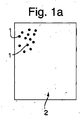
図1では、分布したという用語と、分散したという用語について説明する。マトリックス2に粒子1が含まれている。図1aでは、粒子1が1つの領域で塊状になっている。これらは、分散も分布もしていない。図1bでは、粒子1の複数のランダムな塊が存在する。これらは、分布はしているが分散はしていない。図1cでは、粒子が分散するとともに分布している。
In FIG. 1, the terms distributed and distributed are described. The
図2には工程を示す。当業では、ポリスチレンの一般的押し出し成形が知られている。ホッパ(21)を介して機械(20)にポリスチレン粒体を加え、バレル(23)の内部に位置する重なり共回転軸(22)によってポリスチレン粒体を混入させ、摩擦力及び剪断力を通じてポリスチレンを溶融させる。軸(22)沿いの温度を測定し、温度と圧力が確実に一定になるように制御する。機械(20)の終端では、溶融ポリスチレンがダイ(24)を通じて押し出され、出現するリボン(25)の形状が決定される。その後、冷却され研磨されたローラ(26)にリボン(25)を通して固化させる。 FIG. 2 shows the process. The general extrusion of polystyrene is known in the art. The polystyrene particles are added to the machine (20) via the hopper (21), and the polystyrene particles are mixed by the overlapping co-rotating shaft (22) located inside the barrel (23). Melt. The temperature along the axis (22) is measured and controlled to ensure that the temperature and pressure are constant. At the end of the machine (20), molten polystyrene is extruded through the die (24) to determine the shape of the appearing ribbon (25). Thereafter, the cooled and polished roller (26) is solidified through the ribbon (25).
ここでは、機械(20)は、Rondol Technology社製の2次供給部を備えた2軸押し出しラインである。 Here, the machine (20) is a biaxial extrusion line equipped with a secondary supply unit made by Rondol Technology.
トルエン又は酢酸エチルなどの揮発性液体キャリア中に懸濁しているナノ粒子を、2次供給リザーバ(27)を通じて低圧蠕動ポンプ(28)を介してフローセル(29)内に供給し、ここでバレル(23)の低圧域内に注入する前にナノ粒子を超音波処理する。このナノ粒子を含む揮発性液体キャリアを、低圧蠕動ポンプ(28)によって発生した圧力下でバレル(23)内に連続して注入する(ここで揮発性液体キャリアが軸(22)内に混入されるようになる)。これにより、バレル(23)を通じてポリスチレンが溶融され搬送されるにつれてナノ粒子がポリスチレン内に分散し、搬送される溶融ポリスチレン内に十分に分布したナノ粒子の混合物が形成される。注入前に粒子の凝集を防ぐことによってナノ粒子の完全な分散をさらに確実にするために、ナノ粒子を含む揮発性液体キャリアは、フローセル(29)に入る前にも連続超音波処理を受ける。揮発性液体キャリアは、ダイ(24)を通じた押し出し成形の前に蒸発(30)して再利用され、結果として得られるポリスチレンとナノ粒子の混合物が、冷却され研磨されたローラ(26)上に押し出される。ローラ(26)は対を成し、冷却され、所望の結晶サイズをもたらす冷却速度を生じる。この冷却速度は、スフェルライトを形成することなく最も適した結晶構造を可能にするように制御される。厚さ数ミクロンのリボンでは、わずかな欠陥が製品の品質に大きな影響を与えかねないので、ローラ(26)は、欠陥のない表面を提供するように研磨される。結果として得られる冷却されたリボン(31)は、リール(32)上に巻かれる。 Nanoparticles suspended in a volatile liquid carrier such as toluene or ethyl acetate are fed into the flow cell (29) through the secondary feed reservoir (27) via the low pressure peristaltic pump (28) where the barrel ( 23) Sonicate the nanoparticles before injection into the low pressure zone. The volatile liquid carrier containing the nanoparticles is continuously injected into the barrel (23) under the pressure generated by the low pressure peristaltic pump (28) (where the volatile liquid carrier is mixed into the shaft (22)). Become so). Thus, as the polystyrene is melted and conveyed through the barrel (23), the nanoparticles are dispersed within the polystyrene, forming a well-distributed mixture of nanoparticles within the conveyed molten polystyrene. To further ensure complete dispersion of the nanoparticles by preventing particle agglomeration prior to injection, the volatile liquid carrier containing the nanoparticles is subjected to continuous sonication prior to entering the flow cell (29). The volatile liquid carrier is reused by evaporation (30) prior to extrusion through the die (24) and the resulting mixture of polystyrene and nanoparticles is placed on a cooled and polished roller (26). Extruded. The rollers (26) are paired and cooled to produce a cooling rate that results in the desired crystal size. This cooling rate is controlled to allow the most suitable crystal structure without forming spherulite. For ribbons that are a few microns thick, the roller (26) is polished to provide a defect-free surface, since slight defects can have a significant impact on product quality. The resulting cooled ribbon (31) is wound on a reel (32).
当業者であれば、ポリマー結晶の結晶サイズと機械的内部残留応力との間にはトレードオフが存在するが、このトレードオフは、この応力の一部を低減するための再加熱を通じて排除できると理解するであろう。同様に、所望の厚み及び用途に応じて、鋳造とは対照的に圧延などの他の押し出し/冷却機構を用いてもよい。 Those skilled in the art have a trade-off between the crystal size of the polymer crystal and the mechanical internal residual stress, which can be eliminated through reheating to reduce some of this stress. You will understand. Similarly, other extrusion / cooling mechanisms such as rolling may be used as opposed to casting, depending on the desired thickness and application.
さらなる2次供給物を提供することもできるが、これは任意である。例えば、電圧が必要でない時にはコンデンサが電圧を徐々に落とすことを確実にする電子を提供するように、ナノメートル範囲の銀粒子のさらなる2次供給物を導入することもでき、或いは、所望の誘電特性にとって必要な場合には、異なる高誘導率のナノ粒子を導入することもできる。 Additional secondary feeds can be provided, but this is optional. For example, additional secondary supplies of silver particles in the nanometer range can be introduced to provide electrons that ensure that the capacitor gradually drops the voltage when voltage is not needed, or the desired dielectric If required for the properties, different high inductivity nanoparticles can be introduced.
20 機械
21 ホッパ
22 共回転軸
23 バレル
24 ダイ
25 リボン
26 ローラ
27 2次供給リザーバ
28 低圧蠕動ポンプ
29 フローセル
30 蒸発
31 リボン
32 リール
20
Claims (7)
押し出し機(20)内に熱可塑性粒体を供給するステップと、
液体キャリア中で懸濁しているナノ粒子を含む2次供給物を注入してナノ複合体を形成するステップと、
前記2次供給物を前記押し出し機(20)内に注入しながら前記2次供給物を超音波生成器によって連続的に混合するステップと、
前記ナノ複合体を冷却されたローラ(26)上に予め設定した速度で押し出すことにより、前記誘電体膜(31)の結晶構造の制御を可能にするステップと、を含み、
前記ナノ粒子は、各々が前記熱可塑性粒体内の電子のド・ブロイ波長よりも大きな直径を有さないように幾何学的に制御される、方法。 A method of forming a continuous free-form thermoplastic dielectric film (31) for use at high voltages, uniformly containing dispersed nanoparticles, comprising:
Supplying thermoplastic granules into the extruder (20);
Injecting a secondary feed comprising nanoparticles suspended in a liquid carrier to form a nanocomposite;
Continuously mixing the secondary feed with an ultrasonic generator while injecting the secondary feed into the extruder (20);
Allowing the control of the crystal structure of the dielectric film (31) by extruding the nanocomposite onto a cooled roller (26) at a pre-set speed;
The method wherein the nanoparticles are geometrically controlled such that each does not have a diameter greater than the de Broglie wavelength of the electrons in the thermoplastic granules.
Applications Claiming Priority (3)
| Application Number | Priority Date | Filing Date | Title |
|---|---|---|---|
| GB1212487.1 | 2012-07-13 | ||
| GBGB1212487.1A GB201212487D0 (en) | 2012-07-13 | 2012-07-13 | A device for measuring the hydration level of humans |
| PCT/GB2013/000302 WO2014009686A1 (en) | 2012-07-13 | 2013-07-12 | Process of making a continuous dielectric film comprising dispersed nanoparticles |
Publications (2)
| Publication Number | Publication Date |
|---|---|
| JP2015530936A JP2015530936A (en) | 2015-10-29 |
| JP6100373B2 true JP6100373B2 (en) | 2017-03-22 |
Family
ID=46799572
Family Applications (1)
| Application Number | Title | Priority Date | Filing Date |
|---|---|---|---|
| JP2015521056A Active JP6100373B2 (en) | 2012-07-13 | 2013-07-12 | Method for forming a continuous dielectric film containing dispersed nanoparticles |
Country Status (6)
| Country | Link |
|---|---|
| US (1) | US9518162B2 (en) |
| EP (1) | EP2872311B1 (en) |
| JP (1) | JP6100373B2 (en) |
| CN (1) | CN104619475B (en) |
| GB (2) | GB201212487D0 (en) |
| WO (1) | WO2014009686A1 (en) |
Families Citing this family (15)
| Publication number | Priority date | Publication date | Assignee | Title |
|---|---|---|---|---|
| US10340082B2 (en) | 2015-05-12 | 2019-07-02 | Capacitor Sciences Incorporated | Capacitor and method of production thereof |
| WO2015175558A2 (en) | 2014-05-12 | 2015-11-19 | Capacitor Sciences Incorporated | Energy storage device and method of production thereof |
| US20170301477A1 (en) | 2016-04-04 | 2017-10-19 | Capacitor Sciences Incorporated | Electro-polarizable compound and capacitor |
| US10347423B2 (en) | 2014-05-12 | 2019-07-09 | Capacitor Sciences Incorporated | Solid multilayer structure as semiproduct for meta-capacitor |
| RU2017112074A (en) | 2014-11-04 | 2018-12-05 | Кэпэситор Сайенсиз Инкорпорейтед | DEVICES FOR STORING ENERGY AND METHODS FOR PRODUCING THEM |
| WO2016138310A1 (en) | 2015-02-26 | 2016-09-01 | Capacitor Sciences Incorporated | Self-healing capacitor and methods of production thereof |
| US9932358B2 (en) | 2015-05-21 | 2018-04-03 | Capacitor Science Incorporated | Energy storage molecular material, crystal dielectric layer and capacitor |
| US9941051B2 (en) | 2015-06-26 | 2018-04-10 | Capactor Sciences Incorporated | Coiled capacitor |
| US10026553B2 (en) | 2015-10-21 | 2018-07-17 | Capacitor Sciences Incorporated | Organic compound, crystal dielectric layer and capacitor |
| US20170236642A1 (en) * | 2016-02-12 | 2017-08-17 | Capacitor Sciences Incorporated | para-FURUTA POLYMER AND CAPACITOR |
| US10305295B2 (en) | 2016-02-12 | 2019-05-28 | Capacitor Sciences Incorporated | Energy storage cell, capacitive energy storage module, and capacitive energy storage system |
| US10153087B2 (en) | 2016-04-04 | 2018-12-11 | Capacitor Sciences Incorporated | Electro-polarizable compound and capacitor |
| US9978517B2 (en) | 2016-04-04 | 2018-05-22 | Capacitor Sciences Incorporated | Electro-polarizable compound and capacitor |
| US10395841B2 (en) | 2016-12-02 | 2019-08-27 | Capacitor Sciences Incorporated | Multilayered electrode and film energy storage device |
| CN114889026A (en) * | 2022-05-29 | 2022-08-12 | 山东宙雨消防科技股份有限公司 | Manufacturing method of flame-retardant polystyrene board of external wall thermal insulation material |
Family Cites Families (24)
| Publication number | Priority date | Publication date | Assignee | Title |
|---|---|---|---|---|
| TW408345B (en) * | 1998-04-21 | 2000-10-11 | Matsushita Electric Ind Co Ltd | Capacitor and its manufacturing method |
| JP2000269070A (en) | 1999-03-19 | 2000-09-29 | Matsushita Electric Ind Co Ltd | Manufacturing of capacitor |
| JP2001172412A (en) * | 1999-12-21 | 2001-06-26 | Mitsubishi Polyester Film Copp | Polyethylene-2,6-naphthalate film for capacitor |
| JP2002252143A (en) * | 2000-12-21 | 2002-09-06 | Alps Electric Co Ltd | Temperature compensating thin-film capacitor and electronic apparatus |
| JP2003136658A (en) * | 2001-11-02 | 2003-05-14 | Toray Ind Inc | Biaxially oriented laminated film and condenser using the same |
| US20070176319A1 (en) | 2003-08-06 | 2007-08-02 | University Of Delaware | Aligned carbon nanotube composite ribbons and their production |
| JP4047243B2 (en) | 2003-08-07 | 2008-02-13 | 株式会社日立製作所 | Organic / inorganic oxide mixed thin film, electronic substrate with built-in passive element using the same, and method for producing organic / inorganic oxide mixed thin film |
| US7462666B2 (en) | 2004-05-11 | 2008-12-09 | General Motors Corporation | Method for making nanocomposite materials |
| JP4506957B2 (en) * | 2004-07-20 | 2010-07-21 | Tdk株式会社 | Dielectric particles and manufacturing method thereof, composite dielectric material and substrate |
| US8652391B2 (en) * | 2005-02-03 | 2014-02-18 | Entegris, Inc. | Method of forming substrate carriers and articles from compositions comprising carbon nanotubes |
| KR100674848B1 (en) * | 2005-04-01 | 2007-01-26 | 삼성전기주식회사 | High Capacitancy Metal-Ceramic-Polymer Dielectric Material And Preparing Method For Embedded Capacitor Using The Same |
| CN1900169A (en) | 2005-07-22 | 2007-01-24 | 四川大学 | Preparing nano particle/thermoplastic polymer composite material by flexible method |
| US7662321B2 (en) | 2005-10-26 | 2010-02-16 | Nanotek Instruments, Inc. | Nano-scaled graphene plate-reinforced composite materials and method of producing same |
| US20070116976A1 (en) | 2005-11-23 | 2007-05-24 | Qi Tan | Nanoparticle enhanced thermoplastic dielectrics, methods of manufacture thereof, and articles comprising the same |
| EP2029265B1 (en) | 2006-06-05 | 2013-08-14 | The University of Akron | Ultrasound assisted continuous process and apparatus for dispersion of nanofibers and nanotubes in polymers |
| US20090045544A1 (en) | 2007-08-14 | 2009-02-19 | General Electric Company | Method for manufacturing ultra-thin polymeric films |
| DE102008038667A1 (en) | 2008-08-12 | 2010-02-25 | K+S Ag | Production process of thermoplastic polymers comprising coarse-scale and / or nanoscale, coated, deagglomerated magnesium hydroxide particles and a device for this purpose |
| US20100302707A1 (en) * | 2009-05-26 | 2010-12-02 | General Electric Company | Composite structures for high energy-density capacitors and other devices |
| US20110075320A1 (en) | 2009-09-30 | 2011-03-31 | General Electric Company | Dielectric Film, Associated Article and Method |
| US9159493B2 (en) * | 2010-03-17 | 2015-10-13 | The Secretary Of State For Defense | Dielectrics |
| EP2441792B1 (en) * | 2010-10-13 | 2014-12-17 | Treofan Germany GmbH & Co.KG | Highly active beta-nucleating agent for polypropylene |
| EP2441793B1 (en) * | 2010-10-13 | 2018-08-15 | Treofan Germany GmbH & Co.KG | Highly active beta-nucleation additive for polypropylene |
| JP5679168B2 (en) * | 2010-10-18 | 2015-03-04 | 信越ポリマー株式会社 | Film capacitor film manufacturing method |
| DE102011009433A1 (en) | 2011-01-26 | 2012-07-26 | Gneuß Kunststofftechnik GmbH | Method and device for introducing nanoparticles in plastic melts |
-
2012
- 2012-07-13 GB GBGB1212487.1A patent/GB201212487D0/en not_active Ceased
-
2013
- 2013-07-12 US US14/413,458 patent/US9518162B2/en active Active
- 2013-07-12 WO PCT/GB2013/000302 patent/WO2014009686A1/en active Application Filing
- 2013-07-12 GB GB1312516.6A patent/GB2505764B/en active Active
- 2013-07-12 JP JP2015521056A patent/JP6100373B2/en active Active
- 2013-07-12 EP EP13747681.8A patent/EP2872311B1/en active Active
- 2013-07-12 CN CN201380047341.8A patent/CN104619475B/en active Active
Also Published As
| Publication number | Publication date |
|---|---|
| CN104619475B (en) | 2016-09-14 |
| WO2014009686A1 (en) | 2014-01-16 |
| JP2015530936A (en) | 2015-10-29 |
| GB2505764A (en) | 2014-03-12 |
| CN104619475A (en) | 2015-05-13 |
| EP2872311B1 (en) | 2020-02-19 |
| GB201312516D0 (en) | 2013-08-28 |
| EP2872311A1 (en) | 2015-05-20 |
| GB2505764B (en) | 2016-09-28 |
| US20150291747A1 (en) | 2015-10-15 |
| GB201212487D0 (en) | 2012-08-29 |
| US9518162B2 (en) | 2016-12-13 |
Similar Documents
| Publication | Publication Date | Title |
|---|---|---|
| JP6100373B2 (en) | Method for forming a continuous dielectric film containing dispersed nanoparticles | |
| US20090023851A1 (en) | Process for the production of an electrically conducting polymer composite material | |
| JP4896422B2 (en) | Method for producing fine carbon fiber-containing resin composition | |
| CN101312818B (en) | Thermoplastic resin film and its manufacturing process | |
| KR20070120999A (en) | Thermoplastic molding material and molding elements containing nanometric inorganic particles for making said molding material and said molding elements, and uses thereof | |
| CN101193739A (en) | Method for producing cellulose acylate resin film | |
| JP2011500392A (en) | Polymer material processing apparatus and method | |
| KR102013606B1 (en) | Manufacturing method of thermoplastic resin film and cyclic olefin resin film | |
| CN112388943A (en) | Device for producing plastic melts and use thereof | |
| TW202043003A (en) | Carbon fiber composite material containing recycled carbon fibers, molded body, and method for producing carbon fiber composite material | |
| US6753360B2 (en) | System and method of preparing a reinforced polymer by supercritical fluid treatment | |
| JP2012523972A (en) | Method and system for supplying carbon nanotubes (CNTs) to a fluid to form a composite material | |
| CN114430762A (en) | Liquid crystal polymer film and substrate for high-speed communication | |
| Daniel et al. | Manufacturing issues of polypropylene nanocomposite by melt intercalation process | |
| JP4404702B2 (en) | Method for producing carbon nanowire-dispersed resin composition | |
| ITUA20164096A1 (en) | SCREW FOR EXTRUDER OF POLYMERIC MATERIALS, EXTRUDER OF POLYMERIC MATERIALS INCLUDING THIS SCREW AND METHOD FOR REALIZING EXTRUDED POLYMERIC PRODUCTS | |
| JP2007007864A (en) | Plasticator of on-line blending injection molding machine | |
| Angadi et al. | Effect of screw configuration on the dispersion of nanofillers in thermoset polymers | |
| JP5930881B2 (en) | Gear structure and sheet manufacturing apparatus | |
| CN116635457A (en) | Liquid crystal polymer film and substrate for high-speed communication | |
| Sekyi et al. | Comparative analysis of granule properties in continuous granulators | |
| CN114555329A (en) | Resin extruder, rotor screw, and resin production method | |
| KR102292651B1 (en) | Extruder for high concentration and homogeneous polymer solution and manufacturing process thereof using the same | |
| JP4399525B2 (en) | Method for producing carbon nanowire-dispersed resin composition | |
| WO2021193186A1 (en) | Polymer film and communication board |
Legal Events
| Date | Code | Title | Description |
|---|---|---|---|
| A521 | Request for written amendment filed |
Free format text: JAPANESE INTERMEDIATE CODE: A523 Effective date: 20151021 |
|
| A521 | Request for written amendment filed |
Free format text: JAPANESE INTERMEDIATE CODE: A821 Effective date: 20151021 |
|
| A131 | Notification of reasons for refusal |
Free format text: JAPANESE INTERMEDIATE CODE: A131 Effective date: 20160316 |
|
| A601 | Written request for extension of time |
Free format text: JAPANESE INTERMEDIATE CODE: A601 Effective date: 20160616 |
|
| A601 | Written request for extension of time |
Free format text: JAPANESE INTERMEDIATE CODE: A601 Effective date: 20160815 |
|
| A521 | Request for written amendment filed |
Free format text: JAPANESE INTERMEDIATE CODE: A523 Effective date: 20160916 |
|
| TRDD | Decision of grant or rejection written | ||
| A01 | Written decision to grant a patent or to grant a registration (utility model) |
Free format text: JAPANESE INTERMEDIATE CODE: A01 Effective date: 20170123 |
|
| A61 | First payment of annual fees (during grant procedure) |
Free format text: JAPANESE INTERMEDIATE CODE: A61 Effective date: 20170222 |
|
| R150 | Certificate of patent or registration of utility model |
Ref document number: 6100373 Country of ref document: JP Free format text: JAPANESE INTERMEDIATE CODE: R150 |
|
| R250 | Receipt of annual fees |
Free format text: JAPANESE INTERMEDIATE CODE: R250 |
|
| R250 | Receipt of annual fees |
Free format text: JAPANESE INTERMEDIATE CODE: R250 |
|
| R250 | Receipt of annual fees |
Free format text: JAPANESE INTERMEDIATE CODE: R250 |
|
| R250 | Receipt of annual fees |
Free format text: JAPANESE INTERMEDIATE CODE: R250 |
|
| R250 | Receipt of annual fees |
Free format text: JAPANESE INTERMEDIATE CODE: R250 |