JP6089421B2 - Fuel cell system - Google Patents
Fuel cell system Download PDFInfo
- Publication number
- JP6089421B2 JP6089421B2 JP2012060133A JP2012060133A JP6089421B2 JP 6089421 B2 JP6089421 B2 JP 6089421B2 JP 2012060133 A JP2012060133 A JP 2012060133A JP 2012060133 A JP2012060133 A JP 2012060133A JP 6089421 B2 JP6089421 B2 JP 6089421B2
- Authority
- JP
- Japan
- Prior art keywords
- temperature
- fuel cell
- combustion gas
- stack
- flow rate
- Prior art date
- Legal status (The legal status is an assumption and is not a legal conclusion. Google has not performed a legal analysis and makes no representation as to the accuracy of the status listed.)
- Active
Links
Images


Classifications
-
- Y—GENERAL TAGGING OF NEW TECHNOLOGICAL DEVELOPMENTS; GENERAL TAGGING OF CROSS-SECTIONAL TECHNOLOGIES SPANNING OVER SEVERAL SECTIONS OF THE IPC; TECHNICAL SUBJECTS COVERED BY FORMER USPC CROSS-REFERENCE ART COLLECTIONS [XRACs] AND DIGESTS
- Y02—TECHNOLOGIES OR APPLICATIONS FOR MITIGATION OR ADAPTATION AGAINST CLIMATE CHANGE
- Y02E—REDUCTION OF GREENHOUSE GAS [GHG] EMISSIONS, RELATED TO ENERGY GENERATION, TRANSMISSION OR DISTRIBUTION
- Y02E60/00—Enabling technologies; Technologies with a potential or indirect contribution to GHG emissions mitigation
- Y02E60/30—Hydrogen technology
- Y02E60/50—Fuel cells
Description
本発明は、燃料電池システムに係り、特に、起動時にスタック内の温度分布を均一化する技術に関する。 The present invention relates to a fuel cell system, and more particularly to a technique for equalizing a temperature distribution in a stack at startup.
固体酸化物型燃料電池(SOFC)は高温で発電を行うため、起動時はスタック(燃料電池)を所定の温度まで加熱した後に発電を行う。スタックの加熱方法としては、起動用燃焼器により燃焼ガスを発生し、発生した燃焼ガスをスタック内のカソード流路へ導入する方法が一般的に採用されている。 Since a solid oxide fuel cell (SOFC) generates power at a high temperature, power generation is performed after the stack (fuel cell) is heated to a predetermined temperature during startup. As a method for heating the stack, a method is generally employed in which combustion gas is generated by a start-up combustor and the generated combustion gas is introduced into a cathode flow path in the stack.
また、他の方法として、燃焼ガスを熱交換した高温空気をカソード流路に導入して加熱する方法や、カソード流路への高温空気の導入に加えて、部分酸化反応等で生成したガスをスタックのアノード側に導入する方法、燃焼型や電気式の面ヒータでスタックを加熱する方法等を用いる場合もある。 In addition, as another method, high temperature air obtained by heat exchange of combustion gas is introduced into the cathode channel and heated, or in addition to introduction of high temperature air into the cathode channel, gas generated by partial oxidation reaction or the like is used. In some cases, a method of introducing the anode into the anode of the stack, a method of heating the stack with a combustion type or electric surface heater, or the like may be used.
また、昨今においては、スタックを冷温状態から起動して発電を行い、スタックを停止するまでの総合効率を向上させることが求められており、このためには起動時にスタックを加熱するために使用するエネルギーを極力小さくすることが必要となる。 Also, in recent years, it is required to start the stack from a cold state to generate power and improve the overall efficiency until the stack is stopped. For this purpose, it is used to heat the stack at startup. It is necessary to reduce energy as much as possible.
そこで従来より、スタック温度、及び発電電流値が閾値を超えた際に、起動用燃焼器を停止することにより、起動時におけるエネルギー消費を低減することが提案されている(例えば、特許文献1参照)。 Therefore, conventionally, it has been proposed to reduce the energy consumption at the time of start-up by stopping the start-up combustor when the stack temperature and the generated current value exceed the threshold values (see, for example, Patent Document 1). ).
しかしながら、上述した特許文献1に記載された従来例では、スタック内部の温度分布のばらつきを考慮しておらず、熱容量の低いスタックを使用する場合には、スタック入口からスタック出口までの温度分布の変化により、スタックが劣化、破損する等の問題が発生する可能性があった。 However, in the conventional example described in Patent Document 1 described above, variation in the temperature distribution inside the stack is not considered, and when using a stack having a low heat capacity, the temperature distribution from the stack inlet to the stack outlet Changes could cause problems such as stack deterioration and damage.
本発明は、このような従来の課題を解決するためになされたものであり、その目的とするところは、起動時における耐久性を向上させることのできる燃料電池システムを提供することにある。 The present invention has been made to solve such a conventional problem, and an object of the present invention is to provide a fuel cell system capable of improving durability at the time of startup.
上記目的を達成するため、本発明は、起動時に燃料電池を所定の温度まで昇温する起動モード時に、燃料電池に燃焼ガスを供給すると共に、燃料電池の温度が設定温度に達した際に、燃料電池に供給する燃焼ガスの流量を減少させる。これにより、発電モードが開始される前にスタック温度を均温化する。 In order to achieve the above object, the present invention supplies a combustion gas to the fuel cell in the startup mode in which the temperature of the fuel cell is raised to a predetermined temperature at startup, and when the temperature of the fuel cell reaches a set temperature, Reduce the flow rate of the combustion gas supplied to the fuel cell. As a result, the stack temperature is equalized before the power generation mode is started.
本発明に係る燃料電池システムでは、燃料電池に燃焼ガスを供給して該燃料電池を昇温し、更に、燃料電池の温度が設定温度に達した場合には、燃焼ガス流量を低減することにより、燃料電池温度を均一化する。従って、燃料電池内の温度分布が大きく変化することを防止でき、燃料電池の劣化、損傷を防止することができる。 In the fuel cell system according to the present invention, the combustion gas is supplied to the fuel cell to raise the temperature of the fuel cell. Further, when the temperature of the fuel cell reaches the set temperature, the flow rate of the combustion gas is reduced. , Make the fuel cell temperature uniform. Therefore, it is possible to prevent the temperature distribution in the fuel cell from changing greatly, and to prevent deterioration and damage of the fuel cell.
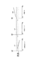
以下、本発明の実施形態を図面に基づいて説明する。図1は、本発明の第1〜第4実施形態に係る燃料電池システムの構成を示すブロック図である。 Hereinafter, embodiments of the present invention will be described with reference to the drawings. FIG. 1 is a block diagram showing a configuration of a fuel cell system according to first to fourth embodiments of the present invention.
図1に示すように、該燃料電池システム100は、カソード11a、及びアノード11bを備えた燃料電池スタック11(以下、「スタック11」と略す)と、カソード11aに空気(酸化ガス)を供給する空気ブロワ12と、該空気ブロワ12より送出される空気を加熱する空気予熱用熱交換器13と、スタック11のアノード11bに炭化水素燃料等の燃料を供給する燃料ポンプ14と、該燃料ポンプ14より送出される燃料を気化させる蒸発器25と、蒸発器25で気化した燃料を改質してアノード11bに供給する燃料改質器15と、を備えている。
As shown in FIG. 1, the
更に、アノード11bより排出される燃料ガスを、燃料改質器15に循環させる昇圧ポンプ17と、カソード11aより排出される排気ガスを導入し、燃料改質器15を加熱する改質器加熱用バーナ16と、昇圧ポンプ17の出力側に設けられ、アノード11bより排出される燃料ガスの一部を改質器加熱用バーナ16に導入する分岐バルブ18と、燃料改質器15及び改質器加熱用バーナ16に空気を供給する空気ブロワ26,27と、を備えている。
Further, a
また、スタック11の起動時に、カソード11aを昇温するための燃焼ガスを生成する起動用燃焼器21を備えており、該起動用燃焼器21には、空気ブロワ12より送出される空気の一部がバルブ22で分岐されて供給され、更に、燃料ポンプ23より送出される燃料が蒸発器24で気化された後に供給される。そして、燃料と空気により燃焼が行われ、燃焼ガスをカソード11aに供給して、スタック11の起動時にカソード11aを昇温する。
In addition, a start-
また、空気ブロワ12、バルブ22、燃料ポンプ23、及びカソード11a(温度センサ等)は、それぞれ制御部31に接続されている。該制御部31は、後述するように、起動時において、起動用燃焼器21に供給する燃料量、及び空気量を調整することにより、起動用燃焼器21から出力される燃焼ガスの流量、及び燃焼ガスの温度を適宜制御して、起動時におけるカソード11a内の温度を均一にする制御を行う。また、制御部31は、例えば、中央演算ユニット(CPU)や、RAM、ROM、ハードディスク等の記憶手段からなる一体型のコンピュータとして構成することができる。
The
[第1実施形態の動作説明]
次に、図2に示すフローチャートを参照して、本発明の第1実施形態に係る燃料電池システムの起動時の動作について説明する。システムの運転を開始する際には、初めに起動モードによりスタック11を昇温し、その後発電モードに移行して発電を行う。
[Description of Operation of First Embodiment]
Next, with reference to the flowchart shown in FIG. 2, the operation | movement at the time of starting of the fuel cell system which concerns on 1st Embodiment of this invention is demonstrated. When starting operation of the system, the
起動モードが開始されると、ステップS11において、制御部31は、起動用燃焼器21に燃料、及び空気を供給した状態で点火し、燃焼させる。そして、燃焼により発生する燃焼ガスはスタック11のカソード11aに供給され、スタック11が昇温される。
When the start mode is started, in step S11, the
ステップS12において、制御部31は、スタック温度Tsを測定し、更に、スタック温度Tsの変化率「dTs/dt」を算出する。スタック温度の測定箇所は、発電開始時や燃焼ガスから空気への切り替え時に温度変動が生じやすいスタック11の上流部に設定することが望ましい。従って、本実施形態では、スタック11の上流部に備えた温度センサ(図示省略)により、スタック温度Tsを測定する。
In step S <b> 12, the
ステップS13において、制御部31は、スタック温度Tsの時間に対する変化率「dTs/dt」が下限閾値Aminと上限閾値Amaxとの間に入っているか否かを判断し、更に、スタック温度Tsが均温化処理を開始するための温度として予め設定した温度T1(設定温度;以下、「均温化開始温度T1」という)に達したか否かを判断する。そして、「Amin≦dTs/dt≦Amax」、及び「Ts≧T1」の少なくとも一方が否定の場合には(ステップS13でNO)、ステップS14に処理を進める。
In step S13, the
ステップS14において、制御部31は、起動用燃焼器21に供給する燃料量、及び空気量を調整し、ステップS13の条件を満たすように制御する。
In step S14, the
一方、「Amin≦dTs/dt≦Amax」であり、且つ「Ts≧T1」である場合には(ステップS13でYES)、ステップS15において、制御部31は、起動用燃焼器21より出力される燃焼ガスの流量Fbを徐々に低下させる。この処理により、カソード11a内の温度が均一となるように調整される。具体的には、燃焼ガスの導入時においてカソード11aは、燃焼ガスが導入される上流側の方が、下流側よりも相対的に温度が高くなるので、燃焼ガスの流量Fbを徐々に低下させることにより、カソード11aの上流から下流全体の温度分布が均一化される。
On the other hand, if “Amin ≦ dTs / dt ≦ Amax” and “Ts ≧ T1” (YES in step S13), the
ステップS16において、制御部31は、スタック温度Tsが、均温化処理中のスタック温度の下限値T2minから上限値T2maxの範囲に入っているか否かを判断し、更に、燃焼ガス流量Fbが、予め設定した設定流量Fb3まで低下したか否かを判断する。即ち、「T2min≦Ts≦T2max」であるか否かを判断し、且つ、「Fb=Fb3」であるか否かを判断する。そして、これらの判断が共に否定である場合には(ステップS16でNO)、ステップS17において、制御部31は、起動用燃焼器21より出力する燃焼ガスの流量Fbを調整して、ステップS16の条件を満たすようにする。
In step S16, the
一方、「T2min≦Ts≦T2max」であり、且つ、「Fb=Fb3」である場合には(ステップS16でYES)、ステップS18において、制御部31は、起動用燃焼器21より出力する燃焼ガスを停止し、更に、スタック11のカソード11aに空気ブロワ12からの空気を導入して、スタック11による発電を開始する。このときの発電電圧Vsを目標電圧V2とする。目標電圧V2は、所定のプログラムに従い、徐々に電圧を低下させて発電電流量を増加させることができる。また、改質器15からアノード11bへの改質オフガスの導入は、スタック温度Tsが均温化開始温度T1に達するまでの加熱昇温ステップの途中(後述の図3に示す時刻t0〜t1間)、或いは、燃焼ガス流量を減少させる均温化ステップの途中(図3に示す時刻t1〜t2間)から行うことができる。
On the other hand, if “T2min ≦ Ts ≦ T2max” and “Fb = Fb3” (YES in step S16), the
ステップS19において、制御部31は、スタック温度Tsが、発電モード時におけるスタック11の目標温度の下限値T3minから上限値T3maxまでの間に入っているか否かを判断する。そして、「T3min≦Ts≦T3max」でなければ(ステップS19でNO)、ステップS20において、カソード11aに供給する空気流量を調整する。例えば、スタック温度TsがT3minより低い場合には、スタック11の温度が低下し過ぎていると判断して、カソード11aの空気流量を減少させる。
In step S19, the
一方、「T3min≦Ts≦T3max」であれば(ステップS19でYES)、ステップS21において、制御部31は、発電電流Isが発電モード開始可能を判断する目標電流値I1に達したか否かを判断する。即ち、「Is=I1」であるか否かを判断する。「Is=I1」でなければ(ステップS21でNO)、ステップS22において、制御部31は、カソード11aに供給する空気流量を増加し、且つ、カソード空気流量から算出される許容電流値限界までに収まるように、電圧を少し下げることで発電電流Isを増加させる。この場合の1ステップ当たりの空気流量増加量と電圧の低下量は予め設定することができる。目標電流値I1は、発電モード開始可能を判断する発電電流値である。その後、ステップS19に処理を戻す。
On the other hand, if “T3min ≦ Ts ≦ T3max” (YES in step S19), in step S21, the
また、発電電流Isが目標電流値I1に達した場合には(ステップS21でYES)、ステップS23において、制御部31は、処理を起動モードから発電モードに移行する。即ち、発電モード開始となり、燃料電池システムから発電出力を取り出し可能となる。
When the generated current Is reaches the target current value I1 (YES in step S21), in step S23, the
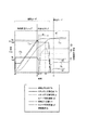
次に、上述の処理手順による各部の温度変化、流量変化を、図3に示す特性図を参照して説明する。図3に示すように、本実施形態では、起動用燃焼器21(図1参照)を作動させて、スタック11による発電が開始されるまでの間の起動モードを、スタック11を含むシステム全体を昇温する加熱昇温ステップ、及び、昇温した後にスタック11全体の温度を均温化する均温化ステップの2つのステップに区別して制御している。そして、均温化ステップの終了後に発電モードへ移行するので、スタック11の上流部から下流部に沿っての温度分布を均温化し、スタック11の急激な熱変動を防止する。
Next, the temperature change and flow rate change of each part by the above-described processing procedure will be described with reference to the characteristic diagram shown in FIG. As shown in FIG. 3, in this embodiment, the start-up combustor 21 (see FIG. 1) is operated, and the start-up mode until power generation by the
加熱昇温ステップでは、時刻t0にて起動用燃焼器21が起動して燃焼ガスが出力され、該燃焼ガスがスタック11に供給されて該スタック11が昇温される。この際、時刻t0〜t1の間では、燃焼ガス温度Tbは徐々に上昇する。これに伴って、スタック温度Ts(本実施形態では、スタック11の上流部温度としている)は、時刻t0〜t1の間で徐々に上昇する。更に、スタック11の下流部温度q1は、スタック温度Tsよりも若干低い温度で徐々に上昇する。この際、起動用燃焼器21より出力される燃焼ガスの流量Fbは、ほぼ一定の流量となるように制御されている。この制御は、制御部31による燃料ポンプ23の燃料送出量、及び空気ブロワ12を調整することにより行うことができる。
In the heating and heating step, the start-up
そして、制御部31は、時刻t1にてスタック温度Tsが予め設定した均温化開始温度T1に達したことを検出し、燃焼ガスの流量Fbが徐々に減少するように制御する(図3のt1〜t3間参照、図2のステップS15参照)。そして、燃焼ガスの流量Fbが時刻t2にて予め設定した設定流量Fb3まで低下すると、起動用燃焼器21よりの燃焼ガスの供給が停止されるので(図2のステップS18参照)、時刻t2から燃焼ガス温度Tbが低下する。
Then, the
また、時刻t2にてバルブ22を切り替えて空気ブロワ12より送出される発電用の空気が熱交換器13で予熱された後カソード11a内に導入されるので、カソード空気流量q3が増加し、且つ、カソード空気温度q2が上昇する。更に、時刻t2にて発電が開始され、発電電流Isが徐々に上昇する。
Further, the power generation air sent from the
その後、発電モードへ移行可能と判断できるスタック温度Tsで発電電流値Is=I1に到達した時刻t3にて均温化ステップが終了し、スタック11による発電モードに移行する。
Thereafter, at the time t3 when the generated current value Is = I1 is reached at the stack temperature Ts at which it can be determined that the mode can be shifted to the power generation mode, the temperature equalizing step ends, and the
こうして、起動用燃焼器21を起動させてスタック11を昇温させる際に、均温化ステップによる処理を実行することにより、カソード11aの上流から下流に至るまでの温度が均温化するように温度を調整し、その後発電モードに移行させることできるのである。
Thus, when the start-up
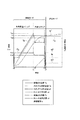
図4は、カソード11aの上流側から下流側の温度分布を示す特性図であり、図4(a)は、本実施形態に係る均温化ステップを採用した場合の特性を示しており、曲線n1は、加温昇温ステップ終了時におけるスタック11の温度分布を示し、曲線n2は、均温化ステップ終了時におけるスタック11の温度分布を示し、曲線n3は、スタック11による発電が行われているときの該スタック11の温度分布を示している。即ち、加温昇温ステップが行われている時には、スタック11に燃焼ガスが供給されるので下流側に対して上流側が高い温度となり、均温化ステップが行われている時には、スタック11の上流側から下流側に沿ってほぼ均一な温度となる。また、発電モード時には、スタック11に空気が供給されるので、上流側に対して下流側が高い温度となる。
FIG. 4 is a characteristic diagram showing the temperature distribution from the upstream side to the downstream side of the
一方、図4(b)は、本実施形態に係る均温化ステップを採用しない場合の特性を示しており、曲線n11〜n14は、起動モードから発電モードに推移するときの、スタック11内の温度分布を示している。
On the other hand, FIG.4 (b) has shown the characteristic at the time of not employ | adopting the temperature equalization step which concerns on this embodiment, and the curves n11-n14 show in the
発電電流とこれに比例する発熱量は温度に比例するため、温度分布n11の状態から、カソード空気に切り替えて発電を開始した場合、温度が高い最上流部で最も発熱量が大きくなる。一方、スタック温度より低温のカソード用空気により最上流部が最も冷却されるため、少し時間が経つと、最上流部より少し下流部で温度が最も高くなるn12の温度分布になる。この状態で発電を継続すると、時間経過に伴って最高温度を示す位置が下流へずれていき、発電モード時の温度分布n14に移行してゆく。特に起動のための昇温エネルギーを小さくするために熱容量を小さくしたスタックにおいては、セパレータやセルの固体部の伝熱で面内温度分布を減少させる効果が小さいため、局所的な発熱による局所的な温度変動が顕著に現れる。そのため起動エネルギーが小さく、起動時間が速い低熱容量スタックにおいては、局所的な温度変動を抑制することは極めて重要な課題である。 Since the power generation current and the heat generation amount proportional thereto are proportional to the temperature, when power generation is started from the state of the temperature distribution n11 by switching to the cathode air, the heat generation amount is greatest at the most upstream part where the temperature is high. On the other hand, since the most upstream part is cooled most by the cathode air having a temperature lower than the stack temperature, after a little time has elapsed, the temperature distribution becomes n12 where the temperature is slightly higher in the downstream part than the most upstream part. If power generation is continued in this state, the position indicating the maximum temperature shifts downstream with the passage of time, and shifts to the temperature distribution n14 in the power generation mode. Especially in a stack with a small heat capacity to reduce the temperature rise energy for startup, the effect of reducing the in-plane temperature distribution by heat transfer in the solid part of the separator or cell is small. Temperature fluctuations are noticeable. For this reason, in a low heat capacity stack with a small start-up energy and a fast start-up time, it is extremely important to suppress local temperature fluctuations.
従って、スタック11に局所的な温度変動が加えられることとなり、スタック11内の温度の偏りや時間的な変動に起因する応力によって、スタック11の劣化や損傷が発生する可能性がある。
Therefore, local temperature fluctuations are applied to the
これに対し、図4(a)に示す各温度分布の曲線n1〜n3から理解されるように、加温昇温ステップが終了した時点では、カソード11aの入口側の温度が高く、出口側の温度が低い状態となっており、均温化ステップを実行することによりカソード11a全体の温度が均一化され、その後、発電を開始することにより、カソード11aの入口側の温度が高く、出口側の温度が低くなるように変化する。
On the other hand, as can be understood from the curves n1 to n3 of the respective temperature distributions shown in FIG. 4A, the temperature on the inlet side of the
この場合、スタック11の温度変化は全体的に直線的な変化であり、スタック11に局所的な温度変動が加えられることがないので、スタック11内の温度の偏りに起因するスタック11の劣化や損傷を防止できることとなる。
In this case, the temperature change of the
このようにして、本発明の第1実施形態に係る燃料電池システムでは、起動用燃焼器21を用いてスタック11を昇温する際に、加熱昇温モードの終了時に、均温化ステップにより燃焼ガスの流量を徐々に低下させているので(即ち、図3のt1〜t2の間で燃焼ガス流量Fbを徐々に低下させているので)、スタック11による発電が開始される前の時点でスタック11の上流側から下流側にかけての全体の温度を均温化することができる。
Thus, in the fuel cell system according to the first embodiment of the present invention, when the temperature of the
従って、カソード上流側のセル温度の急激な温度低下を起こさず、カソード下流側のセル温度を上昇させることにより、カソード流れ方向の温度分布を小さくした後に、発電を開始できるので、セル全体で均質に発電を開始することができるため、局所的な温度変化を抑制することができる。その結果、スタック11の劣化、損傷を防止することが可能となる。
Therefore, power generation can be started after the temperature distribution in the cathode flow direction is reduced by raising the cell temperature on the downstream side of the cathode without increasing the cell temperature on the upstream side of the cathode. Since power generation can be started, local temperature changes can be suppressed. As a result, it is possible to prevent the
また、燃焼ガス流量Fbが設定流量Fb3を下回った場合に、発電を開始するので、スタック11内セルの発電に伴う発熱と燃焼ガスによるセルの冷却或いは加熱の熱量バランスがとり易く、熱容量が小さいスタックにおいても、スタック11内の上流側から下流側への局所的な温度分布の変化を抑制することができる。
In addition, since the power generation is started when the combustion gas flow rate Fb is lower than the set flow rate Fb3, it is easy to balance the amount of heat generated by the power generation of the cells in the
なお、第1実施形態では、燃焼ガス流量Fbを所定のプログラムにより徐々に減少させて流量Fb3となるように制御したが、このほかに、カソード流路上流部と、カソード流路下流部に相当する場所や、熱容量が大きいガスマニホルド部近傍にも温度センサを設定し、上流部の温度情報とともに2点の温度差情報に基づいて、燃焼ガス流量Fbを減少させるよう制御し、Fb3まで下げることもできる。 In the first embodiment, the combustion gas flow rate Fb is controlled to gradually decrease to a flow rate Fb3 by a predetermined program, but in addition to this, it corresponds to the cathode flow channel upstream portion and the cathode flow channel downstream portion. A temperature sensor is also set near the gas manifold where the heat capacity is large and the heat capacity is large, and the combustion gas flow rate Fb is controlled to decrease based on the temperature difference information of the two points together with the temperature information of the upstream portion, and lowered to Fb3 You can also.
燃焼ガス流量Fbの最適な減少のさせ方は、セルの形状や、セルとセルを支える金属支持部やガスマニホルド部との熱容量比、カソードガス流れ構造にも依存し、徐々に減少させることもできるし、段階的に少し減少させて保持し、また減少させるを複数回繰り返すこともできる。 The optimum way of reducing the combustion gas flow rate Fb depends on the shape of the cell, the heat capacity ratio between the cell and the metal support part supporting the cell and the gas manifold part, and the cathode gas flow structure. It is possible to reduce the number in steps and hold it, or to decrease it a plurality of times.
また、燃焼ガス流量Fbは、予め設計或いは測定されているセル各点の加熱昇温マップに基づいて、上流から下流にかけての温度の変動が許容範囲に入るよう設定したプログラムに基づいて減少させることができる。更に、燃焼ガスの停止タイミングは、スタック温度や発電電流値の他、空気予熱用熱交換器13の温度信号に基づいて決定することもできる。
Further, the combustion gas flow rate Fb is decreased based on a program set so that the temperature fluctuation from the upstream to the downstream falls within an allowable range based on the heating temperature increase map at each cell point designed or measured in advance. Can do. Further, the stop timing of the combustion gas can be determined based on the temperature signal of the air preheating
[第2実施形態の動作説明]
次に、図5に示すフローチャートを参照して、第2実施形態に係る燃料電池システムの起動時の動作について説明する。前述した第1実施形態と同様に、システムの運転を開始する際には、初めに起動モードによりスタック11を昇温し、その後発電モードに移行して発電を行う。
[Description of Operation of Second Embodiment]
Next, with reference to the flowchart shown in FIG. 5, the operation | movement at the time of starting of the fuel cell system which concerns on 2nd Embodiment is demonstrated. Similar to the first embodiment described above, when starting the operation of the system, the temperature of the
起動モードが開始されると、ステップS31において、制御部31は、起動用燃焼器21に燃料、及び空気を供給した状態で点火し、燃焼させる。そして、燃焼により発生する燃焼ガスはスタック11のカソード11aに供給され、スタック11が昇温される。
When the start mode is started, in step S31, the
ステップS32において、制御部31は、スタック温度Tsを測定し、更に、スタック温度Tsの変化率「dTs/dt」を算出する。ここでは第1実施形態と同様に、スタック11の上流部に設置した温度センサ(図示省略)により、スタック温度Tsを測定している。
In step S <b> 32, the
ステップS33において、制御部31は、スタック温度Tsの変化率「dTs/dt」が下限閾値Aminと上限閾値Amaxとの間に入っているか否かを判断し、更に、スタック温度Tsが均温化処理を開始するための温度として予め設定した均温化開始温度T1に達したか否かを判断する。そして、「Amin≦dTs/dt≦Amax」、及び「Ts≦T1」の少なくとも一方が否定の場合には(ステップS33でNO)、ステップS34に処理を進める。
In step S33, the
ステップS34において、制御部31は、起動用燃焼器21に供給する燃料量、及び空気量を調整し、ステップS33の条件を満たすように制御する。
In step S34, the
一方、「Amin≦dTs/dt≦Amax」であり、且つ「Ts≦T1」である場合には(ステップS33でYES)、ステップS35において、制御部31は、起動用燃焼器21より出力される燃焼ガスの温度Tbを低下させ、且つ燃焼ガスの流量Fbを低下させる処理を行う。具体的には、スタック温度Tsが均温化開始温度T1に達したときの燃焼ガスの温度をTb1とし、燃焼ガスの流量をFb1とした場合に、燃焼ガスの温度をTb1よりも低いTb2に設定し、燃焼ガスの流量をFb1よりも少ないFb2に設定する。即ち、「Tb=Tb2≦Tb1」、及び「Fb=Fb2≦Fb1」とする。なお、流量Fb2は、発電モード時にカソード11aに供給する空気流量Fcよりも大きく、温度Tb2は、発電モード時にカソード11aに供給する空気温度Tcよりも大きく設定される(後述する図6参照)。
On the other hand, if “Amin ≦ dTs / dt ≦ Amax” and “Ts ≦ T1” (YES in step S33), the
ステップS36において、制御部31は、所定時間の経過を待つ(後述する図6の時刻t1〜t2間)。
In step S36, the
ステップS38において、制御部31は、スタック温度Tsが、均温化処理中のスタック温度の下限値T2min、及び上限値T2maxの範囲に入っているか否かを判断する。そして、この範囲に入っていない場合には(ステップS38でNO)、ステップS39において、制御部31は、ステップS36の処理で用いた所定時間を延長する。
In step S38, the
一方、スタック温度Tsが、均温化処理中のスタック温度の下限値T2min、及び上限値T2maxの範囲に入っていると判断された場合には(ステップS38でYES)、ステップS40において、制御部31は、起動用燃焼器21より出力する燃焼ガスを停止し(図6の時刻t2)、更に、スタック11のカソード11aに空気を供給する。更に、スタック11による発電電圧Vsを、目標電圧V2に設定する。なお、V2≦V1とすることが望ましい。
On the other hand, when it is determined that the stack temperature Ts falls within the range of the lower limit value T2min and the upper limit value T2max of the stack temperature during the temperature equalization process (YES in step S38), in step S40, the
ステップS41において、制御部31は、スタック温度Tsが、発電モード時におけるスタック11の目標温度の下限値T3minから上限値T3maxまでの間に入っているか否かを判断する。そして、「T3min≦Ts≦T3max」でなければ(ステップS41でNO)、ステップS42において、カソード11aに供給する空気流量を調整する。例えば、スタック温度TsがT3minより低下する場合には、スタック11の温度が低下し過ぎていると判断して、カソード11aの空気流量を減少させる。
In step S41, the
一方、「T3min≦Ts≦T3max」であれば(ステップS41でYES)、ステップS43において、制御部31は、発電電流Isが発電モードでの目標電流値I1に達したか否かを判断する。即ち、「Is=I1」であるか否かを判断する。「Is=I1」でなければ(ステップS43でNO)、ステップS44において、制御部31は、カソード11aに供給する空気流量を増加し、且つ、カソード空気流量から算出される許容電流値限界までに収まるように、電圧を少し下げることで発電電流Isを増加させる。この場合の1ステップ当たりの空気流量増加量と電圧の低下量は予め設定することができる。目標電流値I1は、システム要求出力から算出される発電電流である。その後、ステップS41に処理を戻す。
On the other hand, if “T3min ≦ Ts ≦ T3max” (YES in step S41), in step S43, the
また、発電電流Isが目標電流値I1に達した場合には(ステップS43でYES)、ステップS45において、制御部31は、処理を起動モードから発電モードに移行する。即ち、発電モード開始となり、燃料電池システムから発電出力を取り出し可能となる。
If the generated current Is has reached the target current value I1 (YES in step S43), in step S45, the
次に、上述の処理手順による各部の温度変化、流量変化を、図6に示す特性図を参照して説明する。第2実施形態では、前述した第1実施形態と同様に、起動用燃焼器21を作動させて発電モードに至るまでの起動モードが、スタック11を含むシステム全体を昇温する加熱昇温ステップと、昇温した後にスタック11全体の温度を均温化する均温化ステップの2つのステップに区別して制御している。
Next, the temperature change and flow rate change of each part by the above-described processing procedure will be described with reference to the characteristic diagram shown in FIG. In the second embodiment, similarly to the first embodiment described above, the heating mode in which the startup mode until the start-up
加熱昇温ステップでは、時刻t0にて起動用燃焼器21が起動して燃焼ガスが出力され、該燃焼ガスがスタック11に供給されてスタック11が加温される。この際、時刻t0〜t1の間では、燃焼ガス温度Tbは徐々に上昇する。これに伴って、スタック温度(スタックの上流部温度)Tsは時刻t0〜t1の間で徐々に上昇する。更に、スタック11の下流部温度q1は、スタック温度Tsよりも若干低い温度で徐々に上昇する。この際、起動用燃焼器21より出力される燃焼ガスの流量Fbは、ほぼ一定の流量Fb1となるように制御されている。
In the heating temperature raising step, the start-up
そして、制御部31は、時刻t1にてスタック温度Tsが予め設定した均温化開始温度T1に達したことを検出すると、燃焼ガス温度Tbを予め設定した温度Tb2(時刻t1での燃焼ガス温度Tb1よりも低い温度)に減少するように調整し、その後、この温度Tb2を維持する。同様に、燃焼ガスの流量Fbが予め設定したFb2(時刻t1での燃焼ガス流量Fb1よりも少ない流量)まで減少するように調整し、その後、この流量Fb2を維持する。具体的には、図3の時刻t1〜t2間に示すように、燃焼ガス温度Tb、及び燃焼ガス流量Fbを若干減少させ、その後、一定値に維持する制御を行う。この間にスタック11の上流側から下流側全体の温度が均温化されることになる。
When the
そして、時刻t1から所定時間が経過した時刻t2において、起動用燃焼器21よりの燃焼ガスを停止させ、且つ、カソード11aに空気を導入してスタック11による発電を開始する。その後、時刻t3において、発電電流Isが目標電流値I1に達すると、発電モードへと移行する。
At a time t2 when a predetermined time has elapsed from the time t1, the combustion gas from the start-up
ここで、均温化ステップにおいて、燃焼ガス温度Tb、及び燃焼ガス流量Fbを保持する時間(t1〜t2間)は、予め規定した時間とすることもできるし、スタック11内の2点の温度差情報ΔTsに基づき、ΔTs<C(但し、Cは定数)となるまでとして決定することもできる。そして、一定時間保持した後の時刻t2にて、スタック11による発電を開始する。即ち、スタック11のカソード11aに空気を導入して発電を開始する。
Here, in the temperature equalization step, the time (between t1 and t2) for holding the combustion gas temperature Tb and the combustion gas flow rate Fb can be a predetermined time, or two temperatures in the
こうして、起動用燃焼器21を起動させてスタック11を昇温させる際に、均温化ステップによる処理を行うことにより、スタック11の上流から下流に至るまでの温度が均温化するように温度調整し、その後発電モードに移行させることできることとなる。
Thus, when starting up the
このようにして、本発明の第2実施形態に係る燃料電池システムでは、上述した第1実施形態と同様に、スタック11を昇温して設定温度T1に達した後に、均温化ステップによる処理を実行することにより、スタック11全体の温度を均温化することができるので、スタック11に生じる温度差を低減でき、局所的な温度変動に起因するスタック11の劣化、損傷を防止することが可能となる。
As described above, in the fuel cell system according to the second embodiment of the present invention, similarly to the first embodiment described above, after the
また、燃焼ガス温度Tb、及び燃焼ガス流量Fbの双方を低下させて、スタック温度を均温化することにより、スタック11の昇温が終了してから発電を開始するまでに所要する均温化ステップの時間を短縮化することができる。
Further, by reducing both the combustion gas temperature Tb and the combustion gas flow rate Fb to equalize the stack temperature, the temperature equalization required from the end of the temperature increase of the
更に、燃焼ガス温度Tb、及び燃焼ガス流量Fbを低下させた後、この温度、及び流量を一定時間保持するので、下流側の温度上昇を促進することができ、より安定的にスタック温度を均温化することができる。 Further, after the combustion gas temperature Tb and the combustion gas flow rate Fb are lowered, the temperature and the flow rate are maintained for a certain time, so that the temperature rise on the downstream side can be promoted, and the stack temperature can be more stably leveled. Can be warmed.
また、燃焼ガス温度と流量が減少した時刻t2〜空気を導入する時刻t3の間の所定時間経過後に発電を開始するので、上流部の温度を昇温させ過ぎたりせずに、下流部の温度上昇を促進するので、スタック温度が均温化された状態で即時に燃料電池の出力電流を所望する出力電流に到達させることができ、起動までに要する時間を短縮化することができる。 In addition, since power generation is started after a lapse of a predetermined time between time t2 when the combustion gas temperature and flow rate are reduced and time t3 when air is introduced, the temperature of the downstream portion is not increased excessively. Since the increase is promoted, the output current of the fuel cell can be made to reach the desired output current immediately in a state where the stack temperature is equalized, and the time required for starting can be shortened.
更に、燃焼ガスの供給が停止した後に、カソード11aに発電用の空気を供給するので、燃焼ガス、及び発電用空気の双方を同時に制御を行う必要が無く、制御負荷を軽減することができる。
Furthermore, since the power generation air is supplied to the
[第3実施形態の動作説明]
次に、図7に示すフローチャートを参照して、第3実施形態に係る燃料電池システムの起動時の動作について説明する。なお、図7において、ステップS31〜S35までの処理は、図5に示したステップS31〜S35の処理と同一であるので、同一のステップ番号を付して、説明を省略する。ステップS35の処理が終了すると、ステップS51の処理が行われる。
[Description of Operation of Third Embodiment]
Next, with reference to the flowchart shown in FIG. 7, the operation | movement at the time of starting of the fuel cell system which concerns on 3rd Embodiment is demonstrated. In FIG. 7, the processing from step S31 to S35 is the same as the processing from step S31 to S35 shown in FIG. 5, and thus the same step number is assigned and description thereof is omitted. When the process of step S35 ends, the process of step S51 is performed.
ステップS51において、制御部31は、スタック11による発電を開始する。このときの発電電圧Vsを電圧V1に設定する。そして、この電圧V1を徐々に低下させる。
In step S <b> 51, the
ステップS52において、制御部31は、スタック温度Tsが、均温化処理中のスタック温度の下限値T2min、及び上限値T2maxの範囲に入っているか否かを判断する。更に、発電を開始してからの経過時間が予め設定した時間P1に達したか否かを判断する。そして、ステップS52の判断がNOの場合には、ステップS53において、制御部31は、スタック11の発電電圧を調整し、ステップS52の条件を満たすようにする。
In step S52, the
一方、ステップS52の判断がYESの場合には、ステップS54において、制御部31は、起動用燃焼器21より出力する燃焼ガスを停止し、更に、スタック11のカソード11aに空気を導入して、スタック11による発電電圧Vsを目標電圧V2に設定する。なお、V2≦V1が望ましい。
On the other hand, when the determination in step S52 is YES, in step S54, the
ステップS55において、制御部31は、スタック温度Tsが、発電モード時におけるスタック11の目標温度の下限値T3minから上限値T3maxまでの間に入っているか否かを判断する。そして、「T3min≦Ts≦T3max」でなければ(ステップS55でNO)、ステップS56において、カソード11aに供給する空気流量を調整する。例えば、スタック温度TsがT3minより低い場合には、スタック11の温度が低下し過ぎていると判断して、カソード11aの空気流量を減少させる。
In step S55, the
一方、「T3min≦Ts≦T3max」であれば(ステップS55でYES)、ステップS57において、制御部31は、発電電流Isが発電モードでの目標電流値I1に達したか否かを判断する。即ち、「Is=I1」であるか否かを判断する。「Is=I1」でなければ(ステップS57でNO)、ステップS58において、制御部31は、カソード11aに供給する空気流量を増加し、且つ、カソード空気流量から算出される許容電流値限界までに収まるように、電圧を少し下げることで発電電流Isを増加させる。この場合の1ステップ当たりの空気流量増加量と電圧の低下量は予め設定することができる。目標電流値I1は、発電モード開始可能を判断する発電電流である。その後、ステップS55に処理を戻す。
On the other hand, if “T3min ≦ Ts ≦ T3max” (YES in step S55), in step S57, the
また、発電電流Isが目標電流値I1に達した場合には(ステップS57でYES)、ステップS59において、制御部31は、処理を起動モードから発電モードに移行する。即ち、発電モード開始となり、燃料電池システムから発電出力を取り出し可能となる。
When the generated current Is has reached the target current value I1 (YES in step S57), in step S59, the
次に、上述の処理手順による各部の温度変化、流量変化を、図8に示す特性図を参照して説明する。第3実施形態では、前述した第1,第2実施形態と同様に、起動用燃焼器21を作動させて発電モードに至るまでの起動モードを、スタック11を含むシステム全体を昇温する加熱昇温ステップと、昇温した後にスタック11全体の温度を均温化する均温化ステップの2つのステップに区別している。
Next, the temperature change and flow rate change of each part by the above-described processing procedure will be described with reference to the characteristic diagram shown in FIG. In the third embodiment, as in the first and second embodiments described above, the start-up mode from when the start-up
加熱昇温ステップでは、時刻t0にて起動用燃焼器21が起動して燃焼ガスが出力され、該燃焼ガスがスタック11に供給されてスタック11が加熱される。この際、時刻t0〜t1の間では、燃焼ガス温度Tbは徐々に上昇する。これに伴って、スタック温度(スタックの上流部温度)Tsは時刻t0〜t1の間で徐々に上昇する。更に、スタック11の下流部温度q1は、スタック温度Tsよりも若干低い温度で徐々に上昇する。この際、起動用燃焼器21より出力される燃焼ガスの流量Fbは、ほぼ一定の流量Fb1となるように制御されている。
In the heating temperature raising step, the start-up
そして、制御部31は、時刻t1にてスタック温度Tsが予め設定した均温化開始温度T1に達したことを検出すると、燃焼ガス温度Tbを予め設定した温度Tb2(<Tb1)に減少するように調整し、更に、燃焼ガスの流量Fbが予め設定したFb2(<Fb1)まで減少するように調整する。
When the
燃焼ガス温度Tb、及び燃焼ガス流量Fbが低下する時刻t2において、スタック11は発電を開始する(図7のステップS51参照)。そして、スタック11による発電電圧を所定の値で保持するか、或いは、予め設定したプログラムに従って徐々に低下させることにより、時刻t3まで発電電流Isを徐々に増加させる。
At time t2 when the combustion gas temperature Tb and the combustion gas flow rate Fb decrease, the
また、時刻t2の後は、燃焼ガス温度Tbは、Tb2を維持し、燃焼ガス流量Fbは、Fb2を維持する。そして、時刻t2から所定時間P1が経過した時点(時刻t3)で、燃焼ガスの供給が停止され(図7のステップS54参照)、カソード11aに空気を導入し、発電電圧をV2に設定して発電を開始する。スタック温度TsがT3min以上T3max以下となり、発電電流Isが目標電流I1となるよう、空気流量と発電電圧を調整し、その後、時刻t4において、発電電流Isが目標電流値I1に達して、発電モードへと移行する。その結果、時刻t1〜t4の間に、スタック11の上流側から下流側全体の温度が均温化されることになる。
Further, after time t2, the combustion gas temperature Tb maintains Tb2, and the combustion gas flow rate Fb maintains Fb2. Then, when the predetermined time P1 has elapsed from time t2 (time t3), the supply of combustion gas is stopped (see step S54 in FIG. 7), air is introduced into the
こうして、起動用燃焼器21を起動させてスタック11を昇温させる際に、均温化ステップによる処理を行うことにより、スタック11の上流から下流に至るまでの温度が均温化するように温度調整し、その後発電モードに移行させることできるのである。
Thus, when starting up the
このようにして、本発明の第3実施形態に係る燃料電池システムでは、スタック温度Tsが均温化開始温度T1に達した後、燃焼ガス流量と温度を減少させて発電を開始するので、上流部の温度を昇温させ過ぎたり、低下させ過ぎたりせずに安定させながら、下流部の温度を上昇させることができるので、均温化ステップの短縮に加えて加熱昇温ステップの時間短縮をも行うことができ、起動時間を短縮することができる。 Thus, in the fuel cell system according to the third embodiment of the present invention, after the stack temperature Ts reaches the temperature equalization start temperature T1, power generation is started by reducing the combustion gas flow rate and temperature. too raised the temperature of the section, while stabilized without excessive Gitari reduced, it is possible to raise the temperature of the downstream portion, faster time Atsushi Nobori step in addition to the shortening of HitoshiAtsushika step Can also be performed, and the startup time can be shortened.
また、均温化ステップを行う際の燃焼ガス流量を低減することができ、均温化ステップの実行に要する起動バーナに投入する燃料及び空気ブロワの動力を低減できるので、起動のために消費するエネルギーを低減することが可能となる。 Further, the flow rate of the combustion gas at the time of the temperature equalizing step can be reduced, and the power of the fuel and the air blower to be input to the start burner required for executing the temperature equalizing step can be reduced. Energy can be reduced.
ここで、第3実施形態のように、加熱昇温ステップが終了した直後の時刻t2にてスタック11を昇温するための発電を開始する場合は、比較的熱容量の大きいスタックの場合に有利である。熱容量の比較的大きいスタックの場合は、昇温に必要なエネルギーが大きくなるため、起動エネルギー削減が重要課題となるが、発電開始時間が時刻t2に近いほど、起動エネルギーの削減効果は大きくなる。一方、スタック内が十分均温化する前に発電を開始することとなるが、熱容量が大きいスタックでは局所的な発熱に伴う局所的な温度変動は抑制されやすいので、起動モードから発電モードに移行する際のスタック11の温度分布を均一化することができる。
Here, as in the third embodiment, when power generation for raising the temperature of the
[第4実施形態の動作説明]
次に、本発明の第4実施形態について説明する。第4実施形態に係る燃料電池システムは、均温化ステップ中に発電を開始し、上流部も下流部も昇温させながら、上流部と下流部の温度差を小さくする均温化ステップを行うことにより、起動エネルギーを削減して発電開始までに要する時間を短縮する。
[Description of Operation of Fourth Embodiment]
Next, a fourth embodiment of the present invention will be described. The fuel cell system according to the fourth embodiment starts power generation during the temperature equalizing step, and performs the temperature equalizing step to reduce the temperature difference between the upstream portion and the downstream portion while increasing the temperature of both the upstream portion and the downstream portion. As a result, the startup energy is reduced and the time required to start power generation is shortened.
以下、図9に示す特性図を参照して、第4実施形態に係る燃料電池システムの作用について説明する。図9に示す加熱昇温ステップでは、時刻t0にて起動用燃焼器21が起動して燃焼ガスが出力され、該燃焼ガスがスタック11に供給されてスタック11が加温される。この際、時刻t0〜t1の間では、燃焼ガス温度Tbは徐々に上昇する。これに伴って、スタック温度(スタックの上流部温度)Tsは時刻t0〜t1の間で徐々に上昇する。更に、スタック11の下流部温度q1は、スタック温度Tsよりも若干低い温度で徐々に上昇する。この際、起動用燃焼器21より出力される燃焼ガスの流量Fbは、ほぼ一定の流量Fb1となるように制御されている。
The operation of the fuel cell system according to the fourth embodiment will be described below with reference to the characteristic diagram shown in FIG. In the heating temperature raising step shown in FIG. 9, the start-up
そして、制御部31は、時刻t1にてスタック温度Tsが予め設定した均温化開始温度T1に達したことを検出すると、燃焼ガス温度Tbを予め設定した温度Tb2(<Tb1)に減少するように調整し、更に、燃焼ガスの流量Fbが予め設定したFb2(<Fb1)まで減少するように調整する。
When the
その後、燃焼ガス温度Tb、及び燃焼ガス流量Fbが減少する時刻t2において、スタック11による発電を開始する。そして、発電電圧Vsを電圧V1に設定すると、まずスタック11の上流部で発電に伴う発熱が開始され、上流部の温度は昇温速度が低下するが引き続き上昇する。発電可能領域が下流に広がるに従い、下流部も続いて昇温する。燃焼ガスの流量と温度を低下させて発電を開始するため、上流部の昇温速度を低下させ、緩やかに昇温させることができる。これにより最上流部のみが発熱急昇温して熱暴走することを防止している。下流部も昇温して発電可能温度に達すると発熱するため、下流部の昇温速度も引き続き上昇する。発電電流がI2に到達した後、上流部の昇温速度より、電圧Vsを徐々に上昇させ、下流部の温度上昇に伴う電流値の増加速度が鈍るように制御する。発電電流がI2に到達する時刻t3では、スタック内の大部分が発電可能温度に達して上流部の昇温速度より下流部の昇温速度が上回り始める。
Thereafter, power generation by the
その後、発電電流Isが時刻t4にて予め設定した上限電流値I3に達すると、この時刻t4より発電電圧Vsを上昇させて発電電流Isを徐々に低下させる。これにより、下流部の昇温速度は小さくなり、上流部と下流部の温度差が小さく安定した状態になる。なお、時刻t4の時点では、スタック温度Tsは、均温化ステップ開始時の温度T1よりも高い温度となっている。スタック温度TsがT2min以上T2max以下となり、所定の時間P1が経過したら、燃焼ガスの供給を停止し、カソード11aに空気を供給する。スタック温度TsがT3min以上T3max以下となり、発電電流IsがI1となるように、空気流量と発電電圧を調整し、発電電流がIs=I1に達したら発電モードによる発電を開始する。
Thereafter, when the generated current Is reaches the preset upper limit current value I3 at time t4, the generated voltage Vs is increased from time t4 to gradually decrease the generated current Is. As a result, the temperature increase rate in the downstream portion is reduced, and the temperature difference between the upstream portion and the downstream portion is small and stable. At time t4, the stack temperature Ts is higher than the temperature T1 at the start of the temperature equalization step. When the stack temperature Ts becomes equal to or higher than T2min and equal to or lower than T2max and a predetermined time P1 elapses, supply of the combustion gas is stopped and air is supplied to the
次に、スタック11の温度分布の変化を図10に示す特性図を参照して説明する。この実施形態では、加温昇温ステップにて、曲線n21に示すように、スタック11の上流側では発電可能最低温度に達しているが、スタック11の下流側では発電可能最低温度に達していない。そして、均温化ステップを行うことにより、下流側の温度が上昇して曲線n22に示すように、スタック11の温度分布が均一化される。即ち、上流側の温度も上昇すると共に、スタック11の下流側の温度が発電可能最低温度に達する。その後、発電モードに移行すると、曲線n23に示すように、スタック11の下流側の温度が上流側の温度よりも高くなる。
Next, a change in the temperature distribution of the
こうして、均温化ステップが開始されて燃焼ガス温度Tbが低下し、燃焼ガス流量Fbが減少した後に、スタック11による発電を開始し、発電電流Isを上昇させることにより、カソード11aの上流部、下流部の双方の温度を上昇させて、スタック11全体が発電モード時の目標温度へ達するように昇温させることができるのである。
Thus, after the temperature equalization step is started and the combustion gas temperature Tb is reduced and the combustion gas flow rate Fb is reduced, the power generation by the
このようにして、第4実施形態に係る燃料電池システムでは、燃焼ガスの流量温度を低下させた均温化ステップにおいてスタック11による発電を行うことにより、スタック11を昇温させるので、スタック11の下流部の温度が発電可能温度に達していない早い段階から燃焼ガスを作るための起動バーナにかかるエネルギーを低減することができる。また、上流から下流までの平均温度を昇温させながら、均温化することができるので、起動時間を短縮化でき、且つ起動に要するエネルギーを低減することが可能となる。
In this manner, in the fuel cell system according to the fourth embodiment, the
以上、本発明の燃料電池システムを図示の実施形態に基づいて説明したが、本発明はこれに限定されるものではなく、各部の構成は、同様の機能を有する任意の構成のものに置き換えることができる。 Although the fuel cell system of the present invention has been described based on the illustrated embodiment, the present invention is not limited to this, and the configuration of each part is replaced with an arbitrary configuration having the same function. Can do.
例えば、上述した各実施形態では、固体酸化物型燃料電池を用いる例について説明したが、本発明は固体酸化物型燃料電池に限定されるものではなく、高温動作のプロトン伝導性電界質層を用いた燃料電池等に用いることも可能である。また、燃料電池は、平板積層スタック型以外に、チューブ型であっても良い。 For example, in each of the embodiments described above, an example using a solid oxide fuel cell has been described. However, the present invention is not limited to a solid oxide fuel cell, and a proton conductive electrolyte layer operating at a high temperature is used. It can also be used for the fuel cell used. The fuel cell may be a tube type in addition to the flat plate stack type.
本発明は、燃料電池の起動時において燃料電池を均温化することに利用することができる。 The present invention can be used to equalize the temperature of the fuel cell when the fuel cell is started.
11 スタック
11a カソード
11b アノード
12 空気ブロワ
13 空気予熱用熱交換器
14 燃料ポンプ
15 燃料改質器
16 改質器加熱用バーナ
17 昇圧ポンプ
18 分圧バルブ
21 起動用燃焼器
22 バルブ
23 燃料ポンプ
24,25 蒸発器
26,27 空気ブロワ
31 制御部
100 燃料電池システム
DESCRIPTION OF
Claims (9)
前記燃料電池は、起動時に該燃料電池を昇温する起動モード、及び燃料電池が昇温された後に出力要求に応じた発電を行う発電モードで運転され、
前記起動モードにて、前記起動用燃焼器による燃焼ガスを前記燃料電池に供給して前記燃料電池を昇温し、その後、前記燃料電池の温度が、予め設定した設定温度に達した際に、前記燃焼ガスの流量を減少させて前記燃料電池に供給する制御を行う制御手段を備えたことを特徴とする燃料電池システム。 In a fuel cell system comprising at least a fuel cell and a start-up combustor that raises the temperature of the fuel cell during start-up,
The fuel cell is operated in a startup mode in which the temperature of the fuel cell is raised during startup, and in a power generation mode in which power generation is performed in response to an output request after the temperature of the fuel cell is raised,
In the start-up mode, the combustion gas from the start-up combustor is supplied to the fuel cell to raise the temperature of the fuel cell, and then the temperature of the fuel cell reaches a preset set temperature . fuel cell system characterized by comprising a control means for decreasing the flow rate of the previous SL combustion gas performs control for supplying to the fuel cell.
Priority Applications (1)
| Application Number | Priority Date | Filing Date | Title |
|---|---|---|---|
| JP2012060133A JP6089421B2 (en) | 2012-03-16 | 2012-03-16 | Fuel cell system |
Applications Claiming Priority (1)
| Application Number | Priority Date | Filing Date | Title |
|---|---|---|---|
| JP2012060133A JP6089421B2 (en) | 2012-03-16 | 2012-03-16 | Fuel cell system |
Publications (2)
| Publication Number | Publication Date |
|---|---|
| JP2013196819A JP2013196819A (en) | 2013-09-30 |
| JP6089421B2 true JP6089421B2 (en) | 2017-03-08 |
Family
ID=49395541
Family Applications (1)
| Application Number | Title | Priority Date | Filing Date |
|---|---|---|---|
| JP2012060133A Active JP6089421B2 (en) | 2012-03-16 | 2012-03-16 | Fuel cell system |
Country Status (1)
| Country | Link |
|---|---|
| JP (1) | JP6089421B2 (en) |
Families Citing this family (2)
| Publication number | Priority date | Publication date | Assignee | Title |
|---|---|---|---|---|
| KR101958250B1 (en) * | 2017-05-23 | 2019-07-04 | 주식회사 미코 | Fuel-cell system |
| CN114464848B (en) * | 2022-01-24 | 2023-11-24 | 同济大学 | Hydrogen flow load matching control method and device for vehicle-mounted hydrogen supply system |
Family Cites Families (5)
| Publication number | Priority date | Publication date | Assignee | Title |
|---|---|---|---|---|
| JP2005166439A (en) * | 2003-12-02 | 2005-06-23 | Tokyo Gas Co Ltd | Fuel cell system and starting method of the same |
| JP5416347B2 (en) * | 2007-10-12 | 2014-02-12 | 株式会社日立製作所 | Solid oxide fuel cell power generation system and startup method thereof |
| JP5185658B2 (en) * | 2008-02-27 | 2013-04-17 | 三菱重工業株式会社 | Combined system |
| JP2009289577A (en) * | 2008-05-29 | 2009-12-10 | Aisin Seiki Co Ltd | Fuel cell system |
| JP5408420B2 (en) * | 2009-07-30 | 2014-02-05 | 日産自動車株式会社 | FUEL CELL SYSTEM AND FUEL CELL TEMPERATURE METHOD USED FOR THE FUEL CELL SYSTEM |
-
2012
- 2012-03-16 JP JP2012060133A patent/JP6089421B2/en active Active
Also Published As
| Publication number | Publication date |
|---|---|
| JP2013196819A (en) | 2013-09-30 |
Similar Documents
| Publication | Publication Date | Title |
|---|---|---|
| JP6149355B2 (en) | Fuel cell system | |
| JP6040610B2 (en) | Fuel cell system | |
| JP6089421B2 (en) | Fuel cell system | |
| JP5561655B2 (en) | Solid oxide fuel cell device | |
| JP4868268B1 (en) | Solid oxide fuel cell | |
| JP4622005B2 (en) | Solid oxide fuel cell | |
| JP6016382B2 (en) | Fuel cell system and its operation stop method | |
| JP2006309984A (en) | Temperature control method of fuel cell stack structure and fuel cell stack structure | |
| JP5783358B2 (en) | Solid oxide fuel cell | |
| JP4697564B2 (en) | Solid oxide fuel cell | |
| JP5741803B2 (en) | Solid oxide fuel cell device | |
| JP2013164928A (en) | Solid oxide fuel cell system, and operation method of solid oxide fuel cell system | |
| WO2010114042A1 (en) | Solid electrolyte fuel cell | |
| JP5210490B2 (en) | Fuel cell cooling system | |
| JP6102301B2 (en) | Fuel cell system | |
| JP5733512B2 (en) | Solid oxide fuel cell | |
| JP5252238B2 (en) | Solid oxide fuel cell | |
| WO2012043647A1 (en) | Solid oxide fuel cell device | |
| JP5682865B2 (en) | Solid oxide fuel cell device | |
| JP5733682B2 (en) | Solid oxide fuel cell | |
| JPWO2021038257A5 (en) | ||
| JP6390253B2 (en) | Fuel cell power generation system | |
| JP5618070B2 (en) | Solid oxide fuel cell device | |
| JP2021048096A (en) | Fuel cell system and operational method of them | |
| JP6323241B2 (en) | Fuel cell power generation system |
Legal Events
| Date | Code | Title | Description |
|---|---|---|---|
| A621 | Written request for application examination |
Free format text: JAPANESE INTERMEDIATE CODE: A621 Effective date: 20150203 |
|
| A977 | Report on retrieval |
Free format text: JAPANESE INTERMEDIATE CODE: A971007 Effective date: 20160129 |
|
| A131 | Notification of reasons for refusal |
Free format text: JAPANESE INTERMEDIATE CODE: A131 Effective date: 20160202 |
|
| A521 | Written amendment |
Free format text: JAPANESE INTERMEDIATE CODE: A523 Effective date: 20160401 |
|
| A131 | Notification of reasons for refusal |
Free format text: JAPANESE INTERMEDIATE CODE: A131 Effective date: 20160510 |
|
| A521 | Written amendment |
Free format text: JAPANESE INTERMEDIATE CODE: A523 Effective date: 20160701 |
|
| TRDD | Decision of grant or rejection written | ||
| A01 | Written decision to grant a patent or to grant a registration (utility model) |
Free format text: JAPANESE INTERMEDIATE CODE: A01 Effective date: 20170110 |
|
| A61 | First payment of annual fees (during grant procedure) |
Free format text: JAPANESE INTERMEDIATE CODE: A61 Effective date: 20170123 |
|
| R151 | Written notification of patent or utility model registration |
Ref document number: 6089421 Country of ref document: JP Free format text: JAPANESE INTERMEDIATE CODE: R151 |