JP5741803B2 - Solid oxide fuel cell device - Google Patents
Solid oxide fuel cell device Download PDFInfo
- Publication number
- JP5741803B2 JP5741803B2 JP2011000482A JP2011000482A JP5741803B2 JP 5741803 B2 JP5741803 B2 JP 5741803B2 JP 2011000482 A JP2011000482 A JP 2011000482A JP 2011000482 A JP2011000482 A JP 2011000482A JP 5741803 B2 JP5741803 B2 JP 5741803B2
- Authority
- JP
- Japan
- Prior art keywords
- temperature
- fuel cell
- power generation
- reformer
- solid oxide
- Prior art date
- Legal status (The legal status is an assumption and is not a legal conclusion. Google has not performed a legal analysis and makes no representation as to the accuracy of the status listed.)
- Expired - Fee Related
Links
Images


Classifications
-
- Y—GENERAL TAGGING OF NEW TECHNOLOGICAL DEVELOPMENTS; GENERAL TAGGING OF CROSS-SECTIONAL TECHNOLOGIES SPANNING OVER SEVERAL SECTIONS OF THE IPC; TECHNICAL SUBJECTS COVERED BY FORMER USPC CROSS-REFERENCE ART COLLECTIONS [XRACs] AND DIGESTS
- Y02—TECHNOLOGIES OR APPLICATIONS FOR MITIGATION OR ADAPTATION AGAINST CLIMATE CHANGE
- Y02E—REDUCTION OF GREENHOUSE GAS [GHG] EMISSIONS, RELATED TO ENERGY GENERATION, TRANSMISSION OR DISTRIBUTION
- Y02E60/00—Enabling technologies; Technologies with a potential or indirect contribution to GHG emissions mitigation
- Y02E60/30—Hydrogen technology
- Y02E60/50—Fuel cells
Description
本発明は、固体酸化物形燃料電池装置に係わり、特に、燃料と発電用の酸化剤ガスを反応させることにより電力を生成する固体酸化物型燃料電池装置に関する。 The present invention relates to a solid oxide fuel cell device, and more particularly to a solid oxide fuel cell device that generates electric power by reacting a fuel and an oxidant gas for power generation.
従来、固体酸化物形燃料電池装置(SOFC)は、起動工程において、燃料を改質器において改質する工程、すなわち、水蒸気改質反応工程(SR工程)を経て、発電工程へ移行するように構成されている(例えば、特許文献1参照)。
Conventionally, a solid oxide fuel cell device (SOFC) is in the start-up process, the fuel as engineering that inquire reforming in the reformer, i.e., water vapor reforming reaction process (SR process) through, the process proceeds to power step (For example, refer patent document 1).
SOFCでは、この工程を実行することにより、燃料電池モジュール収納室内に配置された改質器や燃料電池セルスタック等を動作温度まで昇温させることができる。SOFCの動作温度は600〜800℃であり、起動工程において、燃料電池セルスタック等をこの温度まで昇温させた後、発電工程が開始される。
In SOFC, by executing this process, it is possible to raise the temperature of the fuel cell module housing chamber disposed a reformer and a fuel cell stack, etc. to operating temperature. The operating temperature of the SOFC is 600 to 800 ° C. After the temperature of the fuel cell stack is raised to this temperature in the startup process, the power generation process is started.
しかしながら、起動工程から発電工程へ移行する際には、起動工程において専ら燃料電池セルスタック等の温度を上昇させるために消費されていた燃料の多くが、電力を生成するために消費されるようになる。このため、起動工程から発電工程への移行時には、燃料電池モジュールの運転状態が大きく変化し、燃料電池セルスタックの急激な温度降下等、運転状態が不安定になりやすいという問題がある。特に、起動工程から発電工程への移行時には、運転状態が大きく変化するため、燃料電池モジュールを制御するために制御部が参照する各種制御パラメータも変動しやすく、この変動により制御パラメータに誤差が生じ、これにより制御が不安定になるという問題もある。 However, when shifting from the start-up process to the power generation process, much of the fuel that was consumed exclusively to raise the temperature of the fuel cell stack or the like in the start-up process is consumed to generate electric power. Become. For this reason, at the time of transition from the start-up process to the power generation process, there is a problem that the operation state of the fuel cell module changes greatly, and the operation state tends to become unstable, such as a rapid temperature drop of the fuel cell stack. In particular, during the transition from the start-up process to the power generation process, the operating state changes greatly, so various control parameters referred to by the control unit to control the fuel cell module are likely to fluctuate, and this fluctuation causes an error in the control parameters. This also causes a problem that the control becomes unstable.
従って、本発明は、起動工程から発電工程へ円滑に移行することができる固体酸化物形燃料電池を提供することを目的としている。 Accordingly, an object of the present invention is to provide a solid oxide fuel cell that can smoothly transition from a startup process to a power generation process.
上述した課題を解決するために、本発明は、燃料と発電用の酸化剤ガスを反応させることにより電力を生成する固体酸化物型燃料電池装置であって、複数の固体電解質型燃料電池セルを備えた燃料電池モジュールと、水蒸気改質を発生させる改質反応であるSR1、及び、SR1よりも少量の燃料を水蒸気改質する改質反応であるSR2を発生させることによって水素を生成する改質器と、この改質器に燃料を供給することにより、改質器で改質された燃料を固体電解質型燃料電池セルに送り込む燃料供給手段と、改質器に改質用の水蒸気を供給する水蒸気供給手段と、固体電解質型燃料電池セルに発電用の酸化剤ガスを供給する発電用酸化剤ガス供給手段と、燃料電池モジュール内の温度を測定する温度検出手段と、燃料供給手段、水蒸気供給手段、及び発電用酸化剤ガス供給手段を制御して、予め決定された温度帯域において、改質器内でSR1、SR2の順序で改質反応を生じさせて燃料電池モジュールから電力を取出可能な発電開始温度まで固体電解質型燃料電池セルを昇温させる起動工程を実行する一方で、起動工程を終了した後、燃料電池モジュールから電力を取出す発電工程を開始するように構成された制御手段と、を有し、制御手段は、起動工程中のSR2において、燃料供給量を一定に維持すると共に、固体電解質型燃料電池セルが発電開始温度に到達している場合でも予め決定されている発電移行時間以上SR2を実行し、発電工程において使用する所定の制御パラメータの初期値を、温度検出手段によって測定された、予め決定されている発電移行時間中における温度の推移に基づいて計算することを特徴としている。 In order to solve the above-described problems, the present invention provides a solid oxide fuel cell device that generates electric power by reacting a fuel with an oxidant gas for power generation, and includes a plurality of solid oxide fuel cell cells. The fuel cell module provided, SR1 which is a reforming reaction for generating steam reforming, and reforming which generates hydrogen by generating SR2 which is a reforming reaction for steam reforming a smaller amount of fuel than SR1 , A fuel supply means for feeding fuel reformed by the reformer to the solid oxide fuel cell by supplying fuel to the reformer, and steam for reforming to the reformer and steam supply means, and generating oxidant gas supply means for supplying oxidant gas for power generation to the solid oxide fuel cell, a temperature detecting means for measuring the temperature of the fuel cell module, the fuel supply means, the water vapor The power supply means and the oxidant gas supply means for power generation can be controlled to generate the reforming reaction in the order of SR1 and SR2 in the reformer in the predetermined temperature band, and to take out the power from the fuel cell module. Control means configured to start a power generation process for extracting power from the fuel cell module after completing the start-up process while performing a start-up process of raising the temperature of the solid oxide fuel cell to a power generation start temperature. The control means maintains the fuel supply amount constant in SR2 during the start-up process, and is determined in advance even when the solid oxide fuel cell has reached the power generation start temperature. running time or SR2, the initial value of the predetermined control parameters used in the power generation process, measured by the temperature detecting means, during the transition time to electrical generation that is predetermined Kicking is characterized by calculating on the basis of transition temperature.
このように構成された本発明においては、制御手段が、燃料供給手段、水蒸気供給手段を夫々制御して、燃料、水蒸気を改質器に供給し、起動工程中に改質器内において、SR1、SR2の各改質反応を順次発生させ水素を生成させる。起動工程により、燃料電池モジュールに備えられた固体電解質型燃料電池セルの温度が発電開始温度まで上昇した後、燃料電池モジュールから電力を取出す発電工程が開始される。制御手段は、起動工程中のSR2において、燃料供給量を一定に維持すると共に、固体電解質型燃料電池セルが発電開始温度に到達している場合でも所定の発電移行時間以上SR2を実行する。制御手段は、発電工程における所定の制御パラメータの初期値を、SR2期間中における制御パラメータの推移に基づいて計算する。In the thus constructed present invention, the control means, fuel supply means, the water vapor supply means respectively controlled by the fuel, the water vapor is supplied to the reformer, in the reformer during the startup process , SR1, SR2 are sequentially generated to generate hydrogen. After the start-up process, the temperature of the solid oxide fuel cell provided in the fuel cell module rises to the power generation start temperature, and then a power generation process for extracting power from the fuel cell module is started. The control means maintains the fuel supply amount constant in SR2 during the starting process, and executes SR2 for a predetermined power generation transition time or more even when the solid oxide fuel cell reaches the power generation start temperature. The control means calculates an initial value of a predetermined control parameter in the power generation process based on the transition of the control parameter during the SR2.
一般に、固体酸化物型燃料電池においては、起動工程から発電工程に移行する際には運転状態が不安定になりやすく、燃料電池モジュールが急激な温度低下を起こすリスクがある。本発明によれば、起動工程中のSR2において、燃料供給量が一定に維持されると共に、所定の発電移行時間以上SR2が維持される。さらに、発電工程における所定の制御パラメータの初期値が、SR2期間中における制御パラメータの推移に基づいて計算される。このため、運転状態が不安定になりやすい発電工程開始時の制御パラメータの初期値を、運転状態が非常に安定しているSR2期間中に整えることができ、制御が不安定になるリスクを抑制することができる。また、制御パラメータの初期値を整えるSR2期間が、少なくとも発電移行時間以上維持されるので、この期間の制御パラメータの推移に基づいて計算される初期値は信頼性の高いものとなり、制御が不安定になるリスクを、より低下させることができる。さらに、制御パラメータの初期値を整えるSR2期間は、SR1よりも燃料供給量が減少されているため、発電工程における運転条件に近い。従って、SR2期間の推移に基づいて計算された制御パラメータの初期値は、発電工程中における制御パラメータと良く整合し、より円滑に発電工程に移行することが可能になる。 In general, in a solid oxide fuel cell, the operation state tends to become unstable when shifting from the start-up process to the power generation process, and there is a risk that the fuel cell module will undergo a rapid temperature drop. According to the present invention, in SR2 during the starting process, the fuel supply amount is maintained constant, and SR2 is maintained for a predetermined power generation transition time or longer. Furthermore, the initial value of the predetermined control parameter in the power generation process is calculated based on the transition of the control parameter during the SR2. For this reason, the initial value of the control parameter at the start of the power generation process, which is likely to be unstable in the operating state, can be adjusted during the SR2 period when the operating state is very stable, thereby suppressing the risk of unstable control. can do. In addition, since the SR2 period for adjusting the initial value of the control parameter is maintained at least for the power generation transition time, the initial value calculated based on the transition of the control parameter during this period is highly reliable and the control is unstable. Can be further reduced. Furthermore, the SR2 period in which the initial values of the control parameters are adjusted is close to the operating conditions in the power generation process because the fuel supply amount is reduced compared to SR1. Therefore, the initial value of the control parameter calculated based on the transition of the SR2 period is in good agreement with the control parameter in the power generation process, and it is possible to shift to the power generation process more smoothly.
本発明において、好ましくは、制御手段は、改質器の温度が所定のSR2移行改質器温度を超え、且つ、固体電解質型燃料電池セルの温度が所定のSR2移行セル温度を超えると、SR1からSR2に移行するように構成される一方、改質器の温度が所定のSR2強制移行温度を超えた場合には、固体電解質型燃料電池セルの温度がSR2移行セル温度に到達する前にSR2に移行させる。 In the present invention, preferably, when the temperature of the reformer exceeds a predetermined SR2 transition reformer temperature and the temperature of the solid oxide fuel cell exceeds a predetermined SR2 transition cell temperature, the control means SR1 When the reformer temperature exceeds the predetermined SR2 forced transition temperature, the solid oxide fuel cell temperature reaches SR2 before the temperature reaches the SR2 transition cell temperature. To migrate.
このように構成された本発明によれば、改質器がSR2強制移行温度を超えた場合にSR2に強制的に移行されるので、SR2期間を発電移行時間以上維持することにより、改質器の温度が過度に上昇するのを抑制することができる。また、温度が過度に上昇することにより、計算された制御パラメータの初期値に誤差が発生するのを抑制することができる。 According to the present invention configured as described above, when the reformer exceeds the SR2 forced transition temperature, the reformer is forcibly shifted to SR2. Therefore, the reformer is maintained by maintaining the SR2 period longer than the power generation transition time. It is possible to suppress an excessive increase in temperature. Moreover, it can suppress that an error generate | occur | produces in the initial value of the calculated control parameter, when temperature rises excessively.
本発明において、好ましくは、制御手段は、起動工程中の、SR2を生じさせている間に、燃料電池モジュールに所定の微弱電力を発電させる。
このように構成された本発明によれば、SR2の実行中に微弱電力を発電させるので、起動工程中における運転状態を発電工程に近似させることができ、より円滑に発電工程に移行することができる。
In the present invention, preferably, the control means causes the fuel cell module to generate a predetermined weak power while generating SR2 during the starting process.
According to the present invention configured as described above, since weak power is generated during the execution of SR2, the operation state in the startup process can be approximated to the power generation process, and the process can be more smoothly shifted to the power generation process. it can.
本発明において、好ましくは、制御手段は、制御パラメータの初期値を、上記発電移行時間中における温度の移動平均により計算する。
このように構成された本発明によれば、燃料供給量が一定に維持されているSR2期間中に制御パラメータの移動平均を計算するので、制御パラメータに混入しているノイズや、外乱の影響を効果的に除去し、信頼性の高い初期値を得ることができる。
In the present invention, preferably, the control means calculates an initial value of the control parameter by a moving average of the temperature during the power generation transition time .
According to the present invention configured as described above, since the moving average of the control parameter is calculated during the SR2 period in which the fuel supply amount is maintained constant, the noise mixed in the control parameter and the influence of disturbances can be reduced. It can be effectively removed and a reliable initial value can be obtained.
本発明において、好ましくは、さらに、燃料電池モジュールで発生した熱を蓄積する蓄熱材を有し、制御手段は、SR2期間中における燃料電池モジュールの温度を積算することにより、制御パラメータの初期値として蓄熱材の蓄熱量を推定する。 In the present invention, preferably, it further includes a heat storage material for accumulating heat generated in the fuel cell module, and the control means integrates the temperature of the fuel cell module during the SR2 period to obtain the initial value of the control parameter. Estimate the amount of heat stored in the heat storage material.
このように構成された本発明によれば、蓄熱材に蓄積されている蓄熱量が制御パラメータの初期値として推定されるので、発電工程において蓄熱を有効に活用することが可能になる。また、信頼性の高い蓄熱量を推定することができるので、蓄熱を利用することによる温度降下のリスクを抑制することができる。 According to the present invention configured as described above, since the heat storage amount accumulated in the heat storage material is estimated as the initial value of the control parameter, it is possible to effectively use the heat storage in the power generation process. Moreover, since the heat storage amount with high reliability can be estimated, the risk of temperature drop due to the use of heat storage can be suppressed.
本発明によれば、起動工程から発電工程へ円滑に移行することができる固体酸化物形燃料電池を提供することができる。 ADVANTAGE OF THE INVENTION According to this invention, the solid oxide fuel cell which can transfer to a power generation process smoothly from a starting process can be provided.
次に、添付図面を参照して、本発明の実施形態による固体酸化物型燃料電池(SOFC)を説明する。
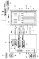
図1は、本発明の一実施形態による固体酸化物型燃料電池(SOFC)を示す全体構成図である。この図1に示すように、本発明の一実施形態による固体酸化物型燃料電池(SOFC)1は、燃料電池モジュール2と、補機ユニット4を備えている。
Next, a solid oxide fuel cell (SOFC) according to an embodiment of the present invention will be described with reference to the accompanying drawings.
FIG. 1 is an overall configuration diagram showing a solid oxide fuel cell (SOFC) according to an embodiment of the present invention. As shown in FIG. 1, a solid oxide fuel cell (SOFC) 1 according to an embodiment of the present invention includes a
燃料電池モジュール2は、ハウジング6を備え、このハウジング6内部には、断熱材7を介して密封空間8が形成されている。この密閉空間8の下方部分である発電室10には、燃料と酸化剤(空気)とにより発電反応を行う燃料電池セル集合体12が配置されている。この燃料電池セル集合体12は、10個の燃料電池セルスタック14(図5参照)を備え、この燃料電池セルスタック14は、16本の燃料電池セルユニット16(図4参照)から構成されている。このように、燃料電池セル集合体12は、160本の燃料電池セルユニット16を有し、これらの燃料電池セルユニット16の全てが直列接続されている。
The
燃料電池モジュール2の密封空間8の上述した発電室10の上方には、燃焼室18が形成され、この燃焼室18で、発電反応に使用されなかった残余の燃料と残余の酸化剤(空気)とが燃焼し、排気ガスを生成するようになっている。
また、この燃焼室18の上方には、燃料を改質する改質器20が配置され、前記残余ガスの燃焼熱によって改質器20を改質反応が可能な温度となるように加熱している。さらに、この改質器20の上方には、改質器20の熱を受けて空気を加熱し、改質器20の温度低下を抑制するための空気用熱交換器22が配置されている。
A
Further, a
次に、補機ユニット4は、水道等の水供給源24からの水を貯水してフィルターにより純水とする純水タンク26と、この貯水タンクから供給される水の流量を調整する水流量調整ユニット28(モータで駆動される「水ポンプ」等)を備えている。また、補機ユニット4は、都市ガス等の燃料供給源30から供給された燃料を遮断するガス遮断弁32と、燃料ガスから硫黄を除去するための脱硫器36と、燃料ガスの流量を調整する燃料流量調整ユニット38(モータで駆動される「燃料ポンプ」等)を備えている。さらに、補機ユニット4は、空気供給源40から供給される酸化剤である空気を遮断する電磁弁42と、空気の流量を調整する改質用空気流量調整ユニット44及び発電用空気流量調整ユニット45(モータで駆動される「空気ブロア」等)と、改質器20に供給される改質用空気を加熱する第1ヒータ46と、発電室に供給される発電用空気を加熱する第2ヒータ48とを備えている。これらの第1ヒータ46と第2ヒータ48は、起動時の昇温を効率よく行うために設けられているが、省略しても良い。
Next, the
次に、燃料電池モジュール2には、排気ガスが供給される温水製造装置50が接続されている。この温水製造装置50には、水供給源24から水道水が供給され、この水道水が排気ガスの熱により温水となり、図示しない外部の給湯器の貯湯タンクへ供給されるようになっている。
また、燃料電池モジュール2には、燃料ガスの供給量等を制御するための制御ボックス52が取り付けられている。
さらに、燃料電池モジュール2には、燃料電池モジュールにより発電された電力を外部に供給するための電力取出部(電力変換部)であるインバータ54が接続されている。
Next, a hot
The
Furthermore, the
次に、図2及び図3により、本発明の実施形態による固体酸化物型燃料電池(SOFC)の燃料電池モジュールの内部構造を説明する。図2は、本発明の一実施形態による固体酸化物型燃料電池(SOFC)の燃料電池モジュールを示す側面断面図であり、図3は、図2のIII-III線に沿って断面図である。
図2及び図3に示すように、燃料電池モジュール2のハウジング6内の密閉空間8には、上述したように、下方から順に、燃料電池セル集合体12、改質器20、空気用熱交換器22が配置されている。
Next, the internal structure of a solid oxide fuel cell (SOFC) fuel cell module according to an embodiment of the present invention will be described with reference to FIGS. FIG. 2 is a side sectional view showing a solid oxide fuel cell (SOFC) fuel cell module according to an embodiment of the present invention, and FIG. 3 is a sectional view taken along line III-III in FIG. .
As shown in FIGS. 2 and 3, in the sealed
改質器20は、その上流端側に純水を導入するための純水導入管60と改質される燃料ガスと改質用空気を導入するための被改質ガス導入管62が取り付けられ、また、改質器20の内部には、上流側から順に、蒸発部20aと改質部20bを形成され、これらの蒸発部20aと改質部20bには改質触媒が充填されている。この改質器20に導入された水蒸気(純水)が混合された燃料ガス及び空気は、改質器20内に充填された改質触媒により改質される。改質触媒としては、アルミナの球体表面にニッケルを付与したものや、アルミナの球体表面にルテニウムを付与したものが適宜用いられる。
The
この改質器20の下流端側には、燃料ガス供給管64が接続され、この燃料ガス供給管64は、下方に延び、さらに、燃料電池セル集合体12の下方に形成されたマニホールド66内で水平に延びている。燃料ガス供給管64の水平部64aの下方面には、複数の燃料供給孔64bが形成されており、この燃料供給孔64bから、改質された燃料ガスがマニホールド66内に供給される。
A fuel
このマニホールド66の上方には、上述した燃料電池セルスタック14を支持するための貫通孔を備えた下支持板68が取り付けられており、マニホールド66内の燃料ガスが、燃料電池セルユニット16内に供給される。
A
次に、改質器20の上方には、空気用熱交換器22が設けられている。この空気用熱交換器22は、上流側に空気集約室70、下流側に2つの空気分配室72を備え、これらの空気集約室70と空気分配室72は、6個の空気流路管74により接続されている。ここで、図3に示すように、3個の空気流路管74が一組(74a,74b,74c,74d,74e,74f)となっており、空気集約室70内の空気が各組の空気流路管74からそれぞれの空気分配室72へ流入する。
Next, an
空気用熱交換器22の6個の空気流路管74内を流れる空気は、燃焼室18で燃焼して上昇する排気ガスにより予熱される。
空気分配室72のそれぞれには、空気導入管76が接続され、この空気導入管76は、下方に延び、その下端側が、発電室10の下方空間に連通し、発電室10に余熱された空気を導入する。
The air flowing through the six air flow path pipes 74 of the
An
次に、マニホールド66の下方には、排気ガス室78が形成されている。また、図3に示すように、ハウジング6の長手方向に沿った面である前面6aと後面6bの内側には、上下方向に延びる排気ガス通路80が形成され、この排気ガス室通路80の上端側は、空気用熱交換器22が配置された空間と連通し、下端側は、排気ガス室78と連通している。また、排気ガス室78の下面のほぼ中央には、排気ガス排出管82が接続され、この排気ガス排出管82の下流端は、図1に示す上述した温水製造装置50に接続されている。
図2に示すように、燃料ガスと空気との燃焼を開始するための点火装置83が、燃焼室18に設けられている。
Next, an
As shown in FIG. 2, an
次に図4により燃料電池セルユニット16について説明する。図4は、本発明の一実施形態による固体酸化物型燃料電池(SOFC)の燃料電池セルユニットを示す部分断面図である。
図4に示すように、燃料電池セルユニット16は、燃料電池セル84と、この燃料電池セル84の上下方向端部にそれぞれ接続された内側電極端子86とを備えている。
燃料電池セル84は、上下方向に延びる管状構造体であり、内部に燃料ガス流路88を形成する円筒形の内側電極層90と、円筒形の外側電極層92と、内側電極層90と外側電極層92との間にある電解質層94とを備えている。この内側電極層90は、燃料ガスが通過する燃料極であり、(−)極となり、一方、外側電極層92は、空気と接触する空気極であり、(+)極となっている。
Next, the
As shown in FIG. 4, the
The
燃料電池セル16の上端側と下端側に取り付けられた内側電極端子86は、同一構造であるため、ここでは、上端側に取り付けられた内側電極端子86について具体的に説明する。内側電極層90の上部90aは、電解質層94と外側電極層92に対して露出された外周面90bと上端面90cとを備えている。内側電極端子86は、導電性のシール材96を介して内側電極層90の外周面90bと接続され、さらに、内側電極層90の上端面90cとは直接接触することにより、内側電極層90と電気的に接続されている。内側電極端子86の中心部には、内側電極層90の燃料ガス流路88と連通する燃料ガス流路98が形成されている。
Since the
内側電極層90は、例えば、Niと、CaやY、Sc等の希土類元素から選ばれる少なくとも一種をドープしたジルコニアとの混合体、Niと、希土類元素から選ばれる少なくとも一種をドープしたセリアとの混合体、Niと、Sr、Mg、Co、Fe、Cuから選ばれる少なくとも一種をドープしたランタンガレードとの混合体、の少なくとも一種から形成される。 The inner electrode layer 90 includes, for example, a mixture of Ni and zirconia doped with at least one selected from rare earth elements such as Ca, Y, and Sc, and Ni and ceria doped with at least one selected from rare earth elements. The mixture is formed of at least one of Ni and a mixture of lanthanum garade doped with at least one selected from Sr, Mg, Co, Fe, and Cu.
電解質層94は、例えば、Y、Sc等の希土類元素から選ばれる少なくとも一種をドープしたジルコニア、希土類元素から選ばれる少なくとも一種をドープしたセリア、Sr、Mgから選ばれる少なくとも一種をドープしたランタンガレート、の少なくとも一種から形成される。 The electrolyte layer 94 includes, for example, zirconia doped with at least one selected from rare earth elements such as Y and Sc, ceria doped with at least one selected from rare earth elements, lanthanum gallate doped with at least one selected from Sr and Mg, Formed from at least one of the following.
外側電極層92は、例えば、Sr、Caから選ばれた少なくとも一種をドープしたランタンマンガナイト、Sr、Co、Ni、Cuから選ばれた少なくとも一種をドープしたランタンフェライト、Sr、Fe、Ni、Cuから選ばれた少なくとも一種をドープしたランタンコバルタイト、銀、などの少なくとも一種から形成される。
The
次に図5により燃料電池セルスタック14について説明する。図5は、本発明の一実施形態による固体酸化物型燃料電池(SOFC)の燃料電池セルスタックを示す斜視図である。
図5に示すように、燃料電池セルスタック14は、16本の燃料電池セルユニット16を備え、これらの燃料電池セルユニット16の下端側及び上端側が、それぞれ、セラミック製の下支持板68及び上支持板100により支持されている。これらの下支持板68及び上支持板100には、内側電極端子86が貫通可能な貫通穴68a及び100aがそれぞれ形成されている。
Next, the
As shown in FIG. 5, the
さらに、燃料電池セルユニット16には、集電体102及び外部端子104が取り付けられている。この集電体102は、燃料極である内側電極層90に取り付けられた内側電極端子86と電気的に接続される燃料極用接続部102aと、空気極である外側電極層92の外周面全体と電気的に接続される空気極用接続部102bとにより一体的に形成されている。空気極用接続部102bは、外側電極層92の表面を上下方向に延びる鉛直部102cと、この鉛直部102cから外側電極層92の表面に沿って水平方向に延びる多数の水平部102dとから形成されている。また、燃料極用接続部102aは、空気極用接続部102bの鉛直部102cから燃料電池セルユニット16の上下方向に位置する内側電極端子86に向って斜め上方又は斜め下方に向って直線的に延びている。
Furthermore, a current collector 102 and an
さらに、燃料電池セルスタック14の端(図5では左端の奥側及び手前側)に位置する2個の燃料電池セルユニット16の上側端及び下側端の内側電極端子86には、それぞれ外部端子104が接続されている。これらの外部端子104は、隣接する燃料電池セルスタック14の端にある燃料電池セルユニット16の外部端子104(図示せず)に接続され、上述したように、160本の燃料電池セルユニット16の全てが直列接続されるようになっている。
Further, the
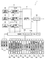
次に図6により本実施形態による固体酸化物型燃料電池(SOFC)に取り付けられたセンサ類等について説明する。図6は、本発明の一実施形態による固体酸化物型燃料電池(SOFC)を示すブロック図である。
図6に示すように、固体酸化物型燃料電池1は、制御部110を備え、この制御部110には、使用者が操作するための「ON」や「OFF」等の操作ボタンを備えた操作装置112、発電出力値(ワット数)等の種々のデータを表示するための表示装置114、及び、異常状態のとき等に警報(ワーニング)を発する報知装置116が接続されている。なお、この報知装置116は、遠隔地にある管理センタに接続され、この管理センタに異常状態を通知するようなものであっても良い。
Next, sensors and the like attached to the solid oxide fuel cell (SOFC) according to the present embodiment will be described with reference to FIG. FIG. 6 is a block diagram illustrating a solid oxide fuel cell (SOFC) according to an embodiment of the present invention.
As shown in FIG. 6, the solid
次に、制御部110には、以下に説明する種々のセンサからの信号が入力されるようになっている。
先ず、可燃ガス検出センサ120は、ガス漏れを検知するためのもので、燃料電池モジュール2及び補機ユニット4に取り付けられている。
CO検出センサ122は、本来排気ガス通路80等を経て外部に排出される排気ガス中のCOが、燃料電池モジュール2及び補機ユニット4を覆う外部ハウジング(図示せず)へ漏れたかどうかを検知するためのものである。
貯湯状態検出センサ124は、図示しない給湯器におけるお湯の温度や水量を検知するためのものである。
Next, signals from various sensors described below are input to the
First, the combustible
The
The hot water storage
電力状態検出センサ126は、インバータ54及び分電盤(図示せず)の電流及び電圧等を検知するためのものである。
発電用空気流量検出センサ128は、発電室10に供給される発電用空気の流量を検出するためのものである。
改質用空気流量センサ130は、改質器20に供給される改質用空気の流量を検出するためのものである。
燃料流量センサ132は、改質器20に供給される燃料ガスの流量を検出するためのものである。
The power
The power generation air flow
The reforming
The
水流量センサ134は、改質器20に供給される純水の流量を検出するためのものである。
水位センサ136は、純水タンク26の水位を検出するためのものである。
圧力センサ138は、改質器20の外部の上流側の圧力を検出するためのものである。
排気温度センサ140は、温水製造装置50に流入する排気ガスの温度を検出するためのものである。
The water
The
The
The
発電室温度センサ142は、図3に示すように、燃料電池セル集合体12の近傍の前面側と背面側に設けられ、燃料電池セルスタック14の近傍の温度を検出して、燃料電池セルスタック14(即ち燃料電池セル84自体)の温度を推定するためのものである。
燃焼室温度センサ144は、燃焼室18の温度を検出するためのものである。
排気ガス室温度センサ146は、排気ガス室78の排気ガスの温度を検出するためのものである。
改質器温度センサ148は、改質器20の温度を検出するためのものであり、改質器20の入口温度と出口温度から改質器20の温度を算出する。
外気温度センサ150は、固体酸化物型燃料電池(SOFC)が屋外に配置された場合、外気の温度を検出するためのものである。また、外気の湿度等を測定するセンサを設けるようにしても良い。
As shown in FIG. 3, the power generation
The combustion
The exhaust gas
The
The outside
これらのセンサ類からの信号は、制御部110に送られ、制御部110は、これらの信号によるデータに基づき、水流量調整ユニット28、燃料流量調整ユニット38、改質用空気流量調整ユニット44、発電用空気流量調整ユニット45に、制御信号を送り、これらのユニットにおける各流量を制御するようになっている。
Signals from these sensors are sent to the
次に図7により本実施形態による固体酸化物型燃料電池(SOFC)による起動時の動作を説明する。図7は、本発明の一実施形態による固体酸化物型燃料電池(SOFC)の起動時の動作を示すタイムチャートである。
最初は、燃料電池モジュール2を温めるために、無負荷状態で、即ち、燃料電池モジュール2を含む回路を開いた状態で、運転を開始する。このとき、回路に電流が流れないので、燃料電池モジュール2は発電を行わない。
Next, the operation at the time of start-up by the solid oxide fuel cell (SOFC) according to the present embodiment will be described with reference to FIG. FIG. 7 is a time chart showing the operation at the start-up of the solid oxide fuel cell (SOFC) according to the embodiment of the present invention.
Initially, in order to warm the
先ず、改質用空気流量調整ユニット44から改質用空気を第1ヒータ46を経由して燃料電池モジュール2の改質器20へ供給する。また、同時に、発電用空気流量調整ユニット45から発電用空気を第2ヒータ48を経由して燃料電池モジュール2の空気用熱交換器22へ供給し、この発電用空気が、発電室10及び燃焼室18に到達する。
この直ぐ後、燃料流量調整ユニット38からも燃料ガスが供給され、改質用空気が混合された燃料ガスが、改質器20及び燃料電池セルスタック14、燃料電池セルユニット16を通過して、燃焼室18に到達する。
First, reforming air is supplied from the reforming air flow
Immediately after this, the fuel gas is also supplied from the fuel flow
次に、点火装置83により着火して、燃焼室18にある燃料ガスと空気(改質用空気及び発電用空気)とを燃焼させる。この燃料ガスと空気との燃焼により排気ガスが生じ、この排気ガスにより、発電室10が暖められ、また、排気ガスが燃料電池モジュール2の密封空間8内を上昇する際、改質器20内の改質用空気を含む燃料ガスを暖めると共に、空気熱交換器22内の発電用空気も暖める。
Next, the
このとき、燃料流量調整ユニット38及び改質用空気流量調整ユニット44により、改質用空気が混合された燃料ガスが改質器20に供給されているので、改質器20において、式(1)に示す部分酸化改質反応POXが進行する。この部分酸化改質反応POXは、発熱反応であるので、起動性が良好となる。また、この昇温した燃料ガスが燃料ガス供給管64により燃料電池セルスタック14の下方に供給され、これにより、燃料電池セルスタック14が下方から加熱され、また、燃焼室18も燃料ガスと空気が燃焼して昇温されているので、燃料電池セルスタック14は、上方からも加熱され、この結果、燃料電池セルスタック14は、上下方向において、ほぼ均等に昇温可能となっている。この部分酸化改質反応POXが進行しても、燃焼室18では継続して燃料ガスと空気との燃焼反応が持続される。
At this time, the fuel gas mixed with the reforming air is supplied to the
CmHn+xO2 → aCO2+bCO+cH2 (1)
C m H n + xO 2 →
部分酸化改質反応POXの開始後、改質器温度センサ148により改質器20が所定温度(例えば、600℃)になったことを検知したとき、水流量調整ユニット28、燃料流量調整ユニット38及び改質用空気流量調整ユニット44により、燃料ガスと改質用空気と水蒸気とを予め混合したガスを改質器20に供給する。このとき、改質器20においては、上述した部分酸化改質反応POXと後述する水蒸気改質反応SRとが併用されたオートサーマル改質反応ATRが進行する。このオートサーマル改質反応ATRは、熱的に内部バランスが取れるので、改質器20内では熱的に自立した状態で反応が進行する。即ち、酸素(空気)が多い場合には部分酸化改質反応POXによる発熱が支配的となり、水蒸気が多い場合には水蒸気改質反応SRによる吸熱反応が支配的となる。この段階では、既に起動の初期段階は過ぎており、発電室10内がある程度の温度まで昇温されているので、吸熱反応が支配的であっても大幅な温度低下を引き起こすことはない。また、オートサーマル改質反応ATRが進行中も、燃焼室18では燃焼反応が継続して行われている。
When the
式(2)に示すオートサーマル改質反応ATRの開始後、改質器温度センサ146により改質器20が所定温度(例えば、700℃)になったことを検知したとき、改質用空気流量調整ユニット44による改質用空気の供給を停止すると共に、水流量調整ユニット28による水蒸気の供給を増加させる。これにより、改質器20には、空気を含まず燃料ガスと水蒸気のみを含むガスが供給され、改質器20において、式(3)の水蒸気改質反応SRが進行する。
When the
CmHn+xO2+yH2O → aCO2+bCO+cH2 (2)
CmHn+xH2O → aCO2+bCO+cH2 (3)
C m H n + xO 2 + yH 2
C m H n + xH 2 O → aCO 2 + bCO + cH 2 (3)
この水蒸気改質反応SRは吸熱反応であるので、燃焼室18からの燃焼熱と熱バランスをとりながら反応が進行する。この段階では、燃料電池モジュール2の起動の最終段階であるため、発電室10内が十分高温に昇温されているので、吸熱反応が進行しても、発電室10が大幅な温度低下を招くこともない。また、水蒸気改質反応SRが進行しても、燃焼室18では継続して燃焼反応が進行する。
Since the steam reforming reaction SR is an endothermic reaction, the reaction proceeds while maintaining a heat balance with the combustion heat from the
このようにして、燃料電池モジュール2は、点火装置83により点火した後、部分酸化改質反応POX、オートサーマル改質反応ATR、水蒸気改質反応SRが、順次進行することにより、発電室10内の温度が徐々に上昇する。次に、発電室10内及び燃料電池セル84の温度が燃料電池モジュール2を安定的に作動させる定格温度よりも低い所定の発電温度に達したら、燃料電池モジュール2を含む回路を閉じ、燃料電池モジュール2による発電を開始し、それにより、回路に電流が流れる。燃料電池モジュール2の発電により、燃料電池セル84自体も発熱し、燃料電池セル84の温度も上昇する。この結果、燃料電池モジュール2を作動させる定格温度、例えば、600℃〜800℃になる。
In this way, after the
この後、定格温度を維持するために、燃料電池セル84で消費される燃料ガス及び空気の量よりも多い燃料ガス及び空気を供給し、燃焼室18での燃焼を継続させる。なお、発電中は、改質効率の高い水蒸気改質反応SRで発電が進行する。
Thereafter, in order to maintain the rated temperature, more fuel gas and air than the amount of fuel gas and air consumed in the
次に、図8により本実施形態による固体酸化物型燃料電池(SOFC)の運転停止時の動作を説明する。図8は、本実施形態により固体酸化物型燃料電池(SOFC)の運転停止時の動作を示すタイムチャートである。
図8に示すように、燃料電池モジュール2の運転停止を行う場合には、先ず、燃料流量調整ユニット38及び水流量調整ユニット28を操作して、燃料ガス及び水蒸気の改質器20への供給量を減少させる。
Next, the operation when the operation of the solid oxide fuel cell (SOFC) according to the present embodiment is stopped will be described with reference to FIG. FIG. 8 is a time chart showing the operation when the solid oxide fuel cell (SOFC) is stopped according to this embodiment.
As shown in FIG. 8, when the operation of the
また、燃料電池モジュール2の運転停止を行う場合には、燃料ガス及び水蒸気の改質器20への供給量を減少させると同時に、改質用空気流量調整ユニット44による発電用空気の燃料電池モジュール2内への供給量を増大させて、燃料電池セル集合体12及び改質器20を空気により冷却し、これらの温度を低下させる。その後、改質器20の温度が所定温度、例えば、400℃まで低下したとき、燃料ガス及び水蒸気の改質器20への供給を停止し、改質器20の水蒸気改質反応SRを終了する。この発電用空気の供給は、改質器20の温度が所定温度、例えば、200℃まで低下するまで、継続し、この所定温度となったとき、発電用空気流量調整ユニット45からの発電用空気の供給を停止する。
Further, when the operation of the
このように、本実施形態においては、燃料電池モジュール2の運転停止を行うとき、改質器20による水蒸気改質反応SRと発電用空気による冷却とを併用しているので、比較的短時間に、燃料電池モジュールの運転を停止させることができる。
As described above, in the present embodiment, when the operation of the
次に、図7及び図9を参照して、本実施形態による固体酸化物形燃料電池(SOFC)の起動時の動作を詳細に説明する。
図9は、燃料電池1の起動処理手順を示す動作テーブルである。図9に示すように、起動工程では、制御部110が各運転制御状態(燃焼運転工程、POX1工程、POX2工程、ATR1工程、ATR2工程、SR1工程、SR2工程)を時間的に順に実行し、発電工程へ移行するように構成されている。
Next, with reference to FIG. 7 and FIG. 9, the operation at the time of starting of the solid oxide fuel cell (SOFC) according to the present embodiment will be described in detail.
FIG. 9 is an operation table showing a startup process procedure of the
なお、POX1工程及びPOX2工程は、改質器20内で部分酸化改質反応が行われる工程である。また、ATR1工程及びATR2工程は、改質器20内でオートサーマル改質反応が行われる工程である。また、SR1工程及びSR2工程は、改質器20内で水蒸気改質反応が行われる工程である。上記各POX工程、ATR工程、SR工程は、それぞれ2つに細分化されているが、これに限らず、3つ以上に細分化してもよいし、細分化しない構成とすることもできる。
The POX1 process and the POX2 process are processes in which a partial oxidation reforming reaction is performed in the
まず、時刻t0において燃料電池1を起動すると、制御部110は、改質用酸化剤ガス供給手段である改質用空気流量調整ユニット44及び発電用酸化剤ガス供給手段である発電用空気流量調整ユニット45に信号を送って、これらを起動させ、改質用空気(酸化剤ガス)及び発電用空気を燃料電池モジュール2に供給する。なお、本実施形態においては、時刻t0において供給が開始される改質用空気の供給量は10.0(L/min)、発電用空気の供給量は100.0(L/min)に設定される(図9の「燃焼運転」工程参照)。
First, when the
次いで、時刻t1において、制御部110は、燃料流量調整ユニット38に信号を送って、改質器20への燃料供給を開始する。これにより、改質器20へ送り込まれた燃料及び改質用空気は、改質器20、燃料ガス供給管64、マニホールド66を介して各燃料電池セルユニット16内に送り込まれる。各燃料電池セルユニット16内に送り込まれた燃料及び改質用空気は、各燃料電池セルユニット16の燃料ガス流路98上端から流出する。なお、本実施形態において、時刻t1において供給が開始される燃料の供給量は6.0(L/min)に設定されている(図9の「燃焼運転」工程参照)。
Next, at time t 1 , the
さらに、時刻t2において、制御部110は、点火装置83に信号を送り、燃料電池セルユニット16から流出する燃料に点火する。これにより、燃焼室18内で燃料が燃焼され、この熱により、その上方に配置された改質器20が加熱されると共に、燃焼室18、発電室10、及びその中に配置された各燃料電池セルユニット16の温度、即ち、燃料電池セルスタック14の温度も上昇する(図7の時刻t2〜t3参照)。燃料ガス流路98を含む燃料電池セルユニット16及びその上端部位は燃焼部に相当する。
Further, at time t 2 , the
改質器20が加熱されることにより、改質器20の温度(以下「改質器温度」という)が300℃程度まで上昇すると、改質器20内においては、部分酸化改質反応(POX)が発生する(図7の時刻t3:POX1工程開始)。このPOX1工程においても、燃料供給量は6.0(L/min)、改質用空気供給量は10.0(L/min)に維持される(図9の「POX1」工程参照)。部分酸化改質反応は発熱反応であるため、改質器20は、部分酸化改質反応の発生により、その反応熱によっても加熱されるようになる(図7の時刻t3〜t5)。
When the temperature of the reformer 20 (hereinafter referred to as “reformer temperature”) rises to about 300 ° C. by heating the
さらに温度が上昇し、改質器温度が350℃に達すると(POX2移行条件)、制御部110は、燃料流量調整ユニット38に信号を送り、燃料供給量を減少させると共に、改質用空気流量調整ユニット38に信号を送り、改質用空気供給量を増加させる(図7の時刻t4:POX2工程開始)。これにより、燃料供給量は5.0(L/min)に変更され、改質用空気供給量は18.0(L/min)に変更される(図9の「POX2」工程参照)。これらの供給量は、部分酸化改質反応を発生させるために適切な供給量である。即ち、部分酸化改質反応が発生し始める初期の温度領域においては、供給する燃料の割合を多くすることにより、燃料に確実に着火させる状態を形成すると共に、その供給量を維持して着火を安定させる(図9の「POX1」工程参照)。さらに、安定して着火され、温度が上昇した後には、部分酸化改質反応を生成するために必要にして十分な燃料供給量として、燃料の浪費を抑えている(図9の「POX2」工程参照)。
When the temperature further rises and the reformer temperature reaches 350 ° C. (POX2 transition condition), the
次に、図7の時刻t5において、改質器温度が600℃以上、且つ、セルスタック温度が250℃以上になると(ATR1移行条件)、制御部110は、改質用空気流量調整ユニット44に信号を送り、改質用空気供給量を減少させると共に、水蒸気供給手段である水流量調整ユニット28に信号を送り、水の供給を開始させる(ATR1工程開始)。これにより、改質用空気供給量は8.0(L/min)に変更され、水供給量は2.0(cc/min)にされる(図9の「ATR1」工程参照)。改質器20内に水(水蒸気)が導入されることにより、改質器20内で水蒸気改質反応も発生するようになる。即ち、図9の「ATR1」工程においては、部分酸化改質反応と水蒸気改質反応が混在したオートサーマル改質(ATR)が発生するようになる。
Next, at time t 5 in FIG. 7, when the reformer temperature is 600 ° C. or higher and the cell stack temperature is 250 ° C. or higher (ATR1 transition condition), the
本実施形態においては、セルスタック温度は、発電室10内に配置された発電室温度センサ142によって測定されている。各燃料電池セルユニット16の温度は完全に均一ではないが、セルスタック温度はそれらの平均的な温度として観念することができる。実際に測定される発電室内の温度とセルスタック温度は、厳密には同一ではないが、発電室温度センサによって検出される温度はセルスタック温度を反映したものであり、発電室内に配置された発電室温度センサにより各燃料電池セルユニット16の平均的な温度を把握することができる。一方、改質器20の温度は改質器温度センサ148で測定されている。なお、本明細書において、セルスタック温度とは、セルスタック温度を反映した値を指示する任意のセンサにより測定された温度を意味するものとする。
In the present embodiment, the cell stack temperature is measured by a power generation
さらに、図7の時刻t6において、改質器温度が600℃以上、且つ、スタック温度が400℃以上になると(ATR2移行条件)、制御部110は、燃料流量調整ユニット38に信号を送り、燃料供給量を減少させる。また、制御部110は、改質用空気流量調整ユニット44に信号を送り、改質用空気供給量を減少させると共に、水流量調整ユニット28に信号を送り、水の供給量を増加させる(ATR2工程開始)。これにより、燃料供給量は4.0(L/min)に変更され、改質用空気供給量は4.0(L/min)に変更され、水供給量は3.0(cc/min)に変更される(図9の「ATR2」工程参照)。改質用空気供給量が減少され、水供給量が増加されることにより、改質器20内においては、発熱反応である部分酸化改質反応の割合が減少し、吸熱反応である水蒸気改質反応の割合が増加する。これにより、改質器温度の上昇は抑制され、一方、改質器20から受けるガス流により燃料電池セルスタック14が昇温されることによって、セルスタック温度は改質器温度に追い付くように昇温していくので、両者の温度差が縮小され、両者は安定的に昇温されていく。
Further, at time t 6 in FIG. 7, the reformer temperature is 600 ° C. or above and the stack temperature is more than 400 ° C. (ATR2 transition condition), the
次に、図7の時刻t7において、改質器温度とセルスタック温度の温度差が縮まり、改質器温度が650℃以上、且つ、スタック温度が600℃以上になると(SR1移行条件)、制御部110は、改質用空気流量調整ユニット44に信号を送り、改質用空気の供給を停止する。また、制御部110は、燃料流量調整ユニット38に信号を送り、燃料供給量を減少させると共に、水流量調整ユニット28に信号を送り、水の供給量を増加させる(SR1工程開始)。これにより、燃料供給量は3.0(L/min)に変更され、水供給量は8.0(cc/min)に変更される(図9の「SR1」工程参照)。改質用空気の供給が停止されることにより、改質器20内においては部分酸化改質反応は発生しなくなり、水蒸気改質反応のみが発生するSRが開始される。
Next, at time t 7 in FIG. 7, when the temperature difference between the reformer temperature and the cell stack temperature is reduced and the reformer temperature is 650 ° C. or higher and the stack temperature is 600 ° C. or higher (SR1 transition condition), The
さらに、図7の時刻t8において、改質器温度とセルスタック温度の温度差がさらに縮まり、改質器温度がSR2移行改質器温度である650℃以上、且つ、セルスタック温度がSR2移行セル温度である650℃以上になると(SR2移行条件)、制御部110は、燃料流量調整ユニット38に信号を送り、燃料供給量を減少させると共に、水流量調整ユニット28に信号を送り、水の供給量も減少させる。また、制御部110は、発電用空気流量調整ユニット45に信号を送り、発電用空気の供給量も減少させる(SR2工程開始)。これにより、燃料供給量は2.3(L/min)に変更され、水供給量は6.3(cc/min)に変更され、発電用空気供給量は80.0(L/min)に変更される(図9の「SR2」工程参照)。また、制御部110に内蔵された蓄熱量推定手段110aは、SR2工程の開始と共に、断熱材7に蓄熱された熱量を推定するために、検出された発電室10の温度の積算を開始する。蓄熱量の推定については後述する。
Further, at time t 8 in FIG. 7, the temperature difference between the reformer temperature and the cell stack temperature is further reduced, the reformer temperature is 650 ° C., which is the SR2 transition reformer temperature, and the cell stack temperature transitions to SR2. When the cell temperature reaches 650 ° C. or higher (SR2 transition condition), the
SR1工程では、改質器温度及びスタック温度を発電可能な温度付近まで上昇させるため、燃料供給量及び水供給量を高めに保持している。その後、SR2工程では、燃料流量及び水供給量を低減して、改質器温度及びセルスタック温度の温度分布を落ち着かせ、発電可能な温度に安定化させる。また、制御部110は、SR2工程開始と共に、燃料電池モジュール2から微弱電力の取り出しを開始する。この微弱電力は一定の電力であり、インバータ54に出力されるものではなく、補機ユニット4を作動させるための電力の一部として利用される。発電工程移行前のSR2工程において一定の微弱電力を取り出すことにより、燃料電池モジュール2の運転を不安定にすることなく、発電工程と近似した運転条件を与えることにより、発電工程への移行がより円滑になる。本実施形態においては、微弱電力は約50Wである。なお、本明細書において、微弱電力とは、固体酸化物形燃料電池1の定格電力の約3%〜15%程度の電力を意味するものとする。
In the SR1 process, the fuel supply amount and the water supply amount are kept high in order to raise the reformer temperature and the stack temperature to near the temperature at which power generation is possible. Thereafter, in the SR2 step, the fuel flow rate and the water supply amount are reduced, the temperature distributions of the reformer temperature and the cell stack temperature are settled, and are stabilized at a temperature at which power generation is possible. Moreover, the
制御部110は、SR2工程において、各供給量を所定の発電移行時間以上維持し、且つ改質器温度が650℃以上、且つ、スタック温度が700℃以上になると(発電工程移行条件)、燃料電池モジュール2からインバータ54に電力を出力させ、発電工程に移行して発電を開始する(図7の時刻t9:発電工程開始)。その後、制御部110は、需要電力に応じた電力を生成できるように、燃料流量調整ユニット38及び水流量調整ユニット28に信号を送って燃料供給量及び水の供給量を変更し、負荷追従運転が実行される。
In the SR2 process, the
なお、制御部110は、SR2工程開始後、発電移行時間が経過する前に、改質器温度650℃、スタック温度700℃に到達している場合であっても、所定の発電移行時間、SR2工程を維持した後、発電工程を開始する。
Note that the
次に、図10を参照して、本実施形態による固体酸化物形燃料電池1を再起動した場合における起動工程の動作を説明する。図10は、固体酸化物形燃料電池1を再起動した場合における、各部の温度、燃料等の供給量の変化の一例を示すグラフである。
Next, with reference to FIG. 10, the operation of the starting process when the solid
図10のグラフは、図7のグラフと同様であるが、断熱材等に多くの熱量が残存している状態から起動工程が開始されるため、図7の場合よりも改質器温度の上昇が速くなっている。図10には、比較のため、図7における改質器温度が細い一点鎖線で示されている。 The graph of FIG. 10 is the same as the graph of FIG. 7, but the start-up process is started from a state in which a large amount of heat remains in the heat insulating material or the like, so the reformer temperature rises more than in the case of FIG. 7. Is getting faster. In FIG. 10, the reformer temperature in FIG. 7 is shown by a thin one-dot chain line for comparison.
図10における「燃焼運転」から「SR1」行程までの移行は、改質器温度の昇温が速く、移行までの時間が短いことを除き図7と同様である。次に、図10の時刻t28においては、セルスタック温度は約630℃であり、改質器温度は700℃である。従って、この状態は、改質器温度はSR2移行改質器温度である650℃を超えているが、セルスタック温度はSR2移行セル温度である650℃に到達していないので、「SR2」工程への通常の移行温度条件には適合していない。しかしながら、制御部110に内蔵された過昇温判断手段110bは、「SR1」行程において改質器温度がSR2強制移行温度である700℃に到達した場合には、過昇温であると判断し、セルスタック温度が650℃に到達する前に強制的に「SR2」工程へ移行させる(図9「SR1」欄における四角囲いの温度条件)。
Transition from “combustion operation” to “SR1” stroke in FIG. 10 is the same as FIG. 7 except that the temperature of the reformer is increased rapidly and the time to transition is short. Next, at time t 28 in FIG. 10, the cell stack temperature is about 630 ° C., and the reformer temperature is 700 ° C. Therefore, in this state, the reformer temperature exceeds the SR2 transition reformer temperature of 650 ° C., but the cell stack temperature does not reach the SR2 transition cell temperature of 650 ° C. It does not meet normal transition temperature conditions. However, when the reformer temperature reaches 700 ° C. which is the SR2 forced transition temperature in the “SR1” stroke, the excessive temperature rise determination unit 110b built in the
「SR2」工程へ移行されると、制御部110は、燃料流量調整ユニット38に信号を送り、燃料供給量を減少させると共に、水流量調整ユニット28に信号を送り、水の供給量も減少させる。また、制御部110は、発電用空気流量調整ユニット45に信号を送り、発電量空気の供給量も減少させる。これにより、燃料供給量は2.3(L/min)に変更され、水供給量は6.3(cc/min)に変更され、発電用空気供給量は80.0(L/min)に変更される。なお、制御部110は、燃料供給量、水供給量、及び発電用空気供給量を約2分間かけてこれらの値まで低下させる(図10の時刻t29)。
When the process proceeds to the “SR2” step, the
次いで、図10の時刻t30においては、セルスタック温度は約680℃であり、改質器温度は720℃である。従って、この状態は、セルスタック温度700℃以上、且つ改質器温度650℃以上である発電工程への通常の移行温度条件には適合していない。しかしながら、制御部110に内蔵された過昇温判断手段110bは、「SR2」工程において改質器温度が発電強制移行温度である720℃に到達した場合には、過昇温が発生していると判断し、セルスタック温度が700℃に到達する前に強制的に発電工程へ移行させる(図9「SR2」欄における四角囲いの温度条件)。
Then, at time t 30 in Figure 10, the cell stack temperature is about 680 ° C., the reformer temperature is 720 ° C.. Therefore, this state does not meet the normal transition temperature conditions for the power generation process in which the cell stack temperature is 700 ° C. or higher and the reformer temperature is 650 ° C. or higher. However, when the reformer temperature reaches 720 ° C., which is the power generation forced transition temperature, in the “SR2” process, the excessive temperature rise determination unit 110b built in the
ただし、制御部110は、燃料供給量、水供給量、及び発電用空気供給量が夫々「SR2」工程における所定の流量に到達した時刻t29の後、少なくとも所定の発電移行時間が経過するまでは、各流量を一定に保持し、「SR2」工程を継続させる。即ち、時刻t29の後、発電移行時間が経過する前に通常の発電移行温度条件が満足され、又は、改質器温度が発電強制移行温度に到達した場合であっても、発電移行時間が経過するまで「SR2」工程が維持され、その後、発電工程が開始される。なお、本実施形態においては、発電移行時間は2分である。
However, the
この発電移行時間は、固体酸化物形燃料電池1の運転が不安定になりやすい発電工程への移行前に、発電移行時間に亘って燃料供給量等を一定値に維持することにより運転状態を安定させるために設けられたものである。また、本実施形態において、制御部110は、後述する蓄熱量や、各部の温度、燃料供給量等、燃料電池モジュール2の制御に必要な各制御パラメータを、温度や流量の各測定値の時間的な推移に基づいて計算し、これに基づいて制御を行っている。即ち、制御部110は、各センサによって測定された温度、流量等に、移動平均や、積分計算等の演算を施して各制御パラメータを得ている。或いは、制御パラメータの1つである蓄熱量は、制御パラメータの1つである発電室温度の積算により推定される。このように、本実施形態においては、各制御パラメータが、それらの時間的な推移に基づいて計算され、SR2期間中の測定値に基づいて計算された各制御パラメータが、発電工程への移行時には、発電工程における各制御パラメータの初期値となる。SR2においては、少なくとも発電移行時間に亘って燃料供給量等が一定値に維持されているため、各測定値も安定したものとなり、発電工程開始時における各制御パラメータの初期値が信頼性の高いものとなる。
The power generation transition time is determined by maintaining the fuel supply amount at a constant value over the power generation transition time before the transition to the power generation process where the operation of the solid
次に、発電工程開始時において、後述する積算により断熱材7に利用可能な熱量が蓄積されていることが推定され、且つ、過昇温判断手段110bが「SR1」工程又は「SR2」工程において過剰な温度上昇が発生していると判断した場合には、制御部110は、過昇温でない場合よりも燃料供給量を減少させ、燃料利用率を高めた高効率運転で発電工程を開始する。このように、通常の発電工程よりも燃料供給量を減少させて発電を行うことにより、燃料電池モジュール2の温度を維持するために燃焼される燃料が減少する。これにより不足した熱量は、断熱材7等に蓄積された熱量により補充される。断熱材7等に蓄積された熱量を消費することにより、過剰に昇温された改質器20等の温度が適正な温度に低下される。このように、燃料利用率を高めた発電工程は、断熱材7等に蓄積された利用可能な熱量がなくなるまで実行される。
Next, at the start of the power generation process, it is estimated that the amount of heat that can be used in the heat insulating material 7 is accumulated by the integration described later, and the excessive temperature rise determination means 110b is in the “SR1” process or the “SR2” process. When it is determined that an excessive temperature rise has occurred, the
次に、図11乃至図14を参照して、燃料電池モジュールに供給される熱量及び蓄熱量の推定を説明する。
図11は、本実施形態の固体酸化物型燃料電池1における出力電流と燃料供給量の関係を示すグラフである。図12は、固体酸化物型燃料電池1における出力電流と、供給された燃料により発生する熱量の関係を示すグラフである。
Next, the estimation of the amount of heat and the amount of stored heat supplied to the fuel cell module will be described with reference to FIGS.
FIG. 11 is a graph showing the relationship between the output current and the fuel supply amount in the solid
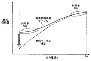
まず、図11の実線に示すように、本実施形態の固体酸化物型燃料電池1は、需要電力に応じて、定格出力電力である700W(出力電流7A)以下で出力を可変できるように構成されている。所要の電力を出力するために必要とされる燃料供給量(L/min)は、図11に実線で示す基本燃料供給テーブルとして設定されている。制御手段である制御部110は、需要電力検出手段である電力状態検出センサ126によって検出された需要電力に応じて、基本燃料供給テーブルに基づいて燃料供給量を決定し、これに基づいて燃料供給手段である燃料流量調整ユニット38を制御するように構成されている。
First, as shown by the solid line in FIG. 11, the solid
発電に必要な燃料の量は出力電力(出力電流)に比例するが、図11に実線で示すように、基本燃料供給テーブルに設定された燃料供給量は、出力電流に比例していない。これは、出力電力に比例して燃料供給量を低下させてしまうと、燃料電池モジュール2内の燃料電池セルユニット16を発電可能な温度に維持することができなくなるためである。このため、本実施形態においては、基本燃料供給テーブルは、出力電流7A付近の大発電電力時には燃料利用率約70%に設定され、出力電流2A程度の小発電電力時には燃料利用率約50%に設定されている。このように、小発電電力領域における燃料利用率を低下させ、発電に使用されなかった燃料を燃焼させて改質器20等の加熱に使用することにより、燃料電池セルユニット16の温度低下を抑制し、燃料電池モジュール2内を発電可能な温度に維持している。
The amount of fuel required for power generation is proportional to the output power (output current), but as shown by the solid line in FIG. 11, the fuel supply amount set in the basic fuel supply table is not proportional to the output current. This is because if the fuel supply amount is reduced in proportion to the output power, the
しかしながら、燃料利用率を低下させることにより、発電に寄与しない燃料を増加させることになるので、小発電電力領域における固体酸化物型燃料電池1のエネルギー効率が低下する。本実施形態の固体酸化物型燃料電池1においては、制御部110に内蔵された燃料テーブル変更手段110c(図6)が、所定の条件に応じて基本燃料供給テーブルに設定された燃料供給量を変更・補正して、燃料供給量を図11の破線に一例を示すように減少させ、小発電電力領域における燃料利用率が上昇される。これにより、固体酸化物型燃料電池1のエネルギー効率が向上される。
However, since the fuel that does not contribute to power generation is increased by reducing the fuel utilization rate, the energy efficiency of the solid
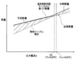
図12は、本実施形態の固体酸化物型燃料電池1において、基本燃料供給テーブルに基づいて燃料を供給した場合における出力電流と、供給された燃料の熱量との関係を模式的に示すグラフである。図12に一点鎖線で示すように、燃料電池モジュール2を熱的に自立させ、安定に運転するために必要な熱量は、出力電流の増加と共に単調に増加する。図12に実線で示すグラフは、基本燃料供給テーブルに従って燃料が供給された場合における熱量を示している。本実施形態では、中発電電力に相当する出力電流5Aよりも低い領域では、一点鎖線で示す必要な熱量と、実線で示す基本燃料供給テーブルに基づいて供給される熱量がほぼ一致している。
FIG. 12 is a graph schematically showing the relationship between the output current and the amount of heat of the supplied fuel when the fuel is supplied based on the basic fuel supply table in the solid
さらに、出力電流5Aよりも高い領域では、基本燃料供給テーブルに従って供給される実線で示す熱量は、熱自立するために最低限必要な一点鎖線で示す熱量を上回っている。この実線と破線の間の余剰熱量は、燃料電池モジュール2に設けられた蓄熱材である断熱材7に蓄積される。また、固体酸化物型燃料電池1から大きな出力電流を取り出すと、燃料電池セルユニット16内部の発熱が大きくなり、燃料電池モジュール2内の温度が上昇する。このため、固体酸化物型燃料電池1からの出力電流と、この電流を定常的に出力している場合における燃料電池モジュール2内の燃料電池セルユニット16の温度とは相関があり、出力電流が大きい状態では燃料電池セルユニット16の温度は高い状態にある。本実施形態においては、出力電流5Aは、蓄熱温度Thである約633℃に対応している。従って、本実施形態の固体酸化物型燃料電池1では、出力電流5A、蓄熱温度Th=約633℃以上の場合において、より多くの熱量が断熱材7に蓄積される。
Further, in a region higher than the output current 5A, the amount of heat indicated by the solid line supplied in accordance with the basic fuel supply table exceeds the amount of heat indicated by the one-dot chain line necessary for heat self-sustainment. The surplus heat amount between the solid line and the broken line is accumulated in the heat insulating material 7 that is a heat storage material provided in the
この蓄熱温度Thは、発電電力範囲である0W〜700Wの中央値である350Wよりも大きい500W(出力電流5A)に対応する温度に設定されている。また、出力電流5A以下の領域においては、基本燃料供給テーブルに基づいて供給される熱量は、熱自立するために最低限必要な熱量とほぼ同一(僅かに基本燃料供給テーブルの熱量が大きい)に設定されている。このため、図12の破線に一例を示すように、基本燃料供給テーブルによる燃料供給量が補正され、燃料供給量が減少されると、熱的に自立するために必要な熱量が不足する。 This heat storage temperature Th is set to a temperature corresponding to 500 W (output current 5 A) that is larger than 350 W, which is the median value of 0 W to 700 W that is the generated power range. In the region where the output current is 5 A or less, the amount of heat supplied based on the basic fuel supply table is substantially the same as the minimum amount of heat necessary for heat self-sustainment (the amount of heat of the basic fuel supply table is slightly larger). Is set. For this reason, as shown by an example of the broken line in FIG. 12, when the fuel supply amount by the basic fuel supply table is corrected and the fuel supply amount is reduced, the heat amount necessary for thermal independence is insufficient.
本実施形態においては、後述するように、発電電力が小さい領域において、基本燃料供給テーブルで設定された燃料供給量を一時的に減少させるように補正して、燃料利用率を向上させる。一方、基本燃料供給テーブルの燃料供給量を減少させたことにより不足する熱量は、燃料電池モジュール2が蓄熱温度Thよりも高い領域で運転されている間に断熱材7に蓄積された熱量を利用して補充している。なお、本実施形態においては、断熱材7の熱容量が非常に大きいため、燃料電池モジュール2が大発電電力で所定時間運転された後、発電電力が小さい領域で運転される場合には、断熱材7に蓄積された熱量を2時間以上に亘って利用することができ、この間の燃料供給量を減じる補正を行うことにより燃料利用率が向上される。
In the present embodiment, as will be described later, in a region where the generated power is small, the fuel supply rate set in the basic fuel supply table is corrected so as to be temporarily reduced to improve the fuel utilization rate. On the other hand, the amount of heat that is deficient by reducing the fuel supply amount of the basic fuel supply table uses the amount of heat accumulated in the heat insulating material 7 while the
また、本実施形態においては、出力電流5A、蓄熱温度Th=約633℃以上の場合において、より多くの熱量が断熱材7に蓄積されるように基本燃料供給テーブルが設定されているが、出力電流5A以上の領域においても熱自立するために最低限必要な熱量とほぼ同一(僅かに基本燃料供給テーブルの熱量が大きい)に基本燃料供給テーブルを設定することもできる。即ち、発電電力が大きい領域においては、燃料電池モジュール2の作動温度は、発電電力が小さい場合よりも高いので、燃料供給量が熱自立のための必要最低限の熱量に設定されていても、小発電電力時に利用可能な熱量を断熱材7に蓄積することができる。本実施形態のように、大発電電力時に積極的に燃料供給量を多く設定しておくことにより、電力需要がピークとなる夜間帯の短時間で断熱材7に必要な熱量を確実に蓄積させることができる。
In the present embodiment, the basic fuel supply table is set so that more heat is accumulated in the heat insulating material 7 when the output current is 5A and the heat storage temperature Th is about 633 ° C. or higher. Even in the region where the current is 5 A or more, the basic fuel supply table can be set to be substantially the same as the minimum amount of heat necessary for heat self-sustainment (the amount of heat of the basic fuel supply table is slightly larger). That is, in the region where the generated power is large, the operating temperature of the
次に、図13及び図14を参照して、断熱材7等に蓄積されている蓄熱量の推定を具体的に説明する。
図13は、断熱材7に蓄積された熱量を推定するために使用される蓄熱量推定テーブルである。図14は、蓄熱量推定テーブルをグラフ化したものである。
Next, with reference to FIG.13 and FIG.14, estimation of the heat storage amount accumulate | stored in the heat insulating material 7 grade | etc., Is demonstrated concretely.
FIG. 13 is a heat storage amount estimation table used for estimating the amount of heat accumulated in the heat insulating material 7. FIG. 14 is a graph of the heat storage amount estimation table.
蓄熱量の推定は、制御部110に内蔵されている蓄熱量推定手段110a(図6)により実行される。蓄熱量推定手段110aは、燃料供給量、水供給量、及び発電用空気供給量が夫々「SR2」工程における所定の流量に到達した時刻t29(図10)の後、蓄熱量の推定を開始する。即ち、蓄熱量推定手段110aは、温度検出手段である発電室温度センサ142の検出温度Tdに基づいて、図13に示す蓄熱量推定テーブルを参照し、加減算値を決定する。この加減算値は、所定の時間間隔で決定され、順次積算されて積算値Niが計算される。本実施形態においては、0.5secに1回ずつ積算が実行される。
The estimation of the heat storage amount is executed by the heat storage amount estimation means 110a (FIG. 6) built in the
このような積算値Niは、燃料電池モジュール2や発電室10内の温度の推移・履歴を反映するものであり、断熱材7等に蓄積されている蓄熱量の程度を示す指標となる値である。この積算値Niは、蓄熱最小値である0から蓄熱最大値である1の間の値を取るように計算される。即ち、積算値Niが1に到達した場合には、値は次に減算が行われるまで1に保持され、積算値Niが0まで減少した場合には、値は次に加算が行われるまで0に保持される。また、本実施形態においては、図10の時刻t29において積算値Niの積算を開始する際、蓄熱最小値と蓄熱最大値の中間値である0.5よりも大きい0.7を積算値Niの初期値として積算が開始される。この初期値は、「SR1」工程までの起動工程において最低限蓄積されていると考えられる蓄熱量に相当する値である。
Such an integrated value Ni reflects a transition / history of the temperature in the
本明細書においては、本実施形態における積算値Niのように、蓄熱量の程度を示す指標となる値が蓄熱量の推定値であるとする。従って、本実施形態においては、燃料電池モジュール2の温度に基づいて蓄熱量が推定される。
In the present specification, it is assumed that a value serving as an index indicating the degree of the heat storage amount is an estimated value of the heat storage amount, like the integrated value Ni in the present embodiment. Therefore, in this embodiment, the heat storage amount is estimated based on the temperature of the
図13に示すように、例えば、検出温度Tdが645℃である場合には、加減算値は1/50000に決定される。決定された加減算値は、積算値Niに加算される。従って、検出温度Tdが645℃で一定の場合には、0.5secに1回ずつ1/50000の値が積算され、積算値Niが増加する。 As shown in FIG. 13, for example, when the detected temperature Td is 645 ° C., the addition / subtraction value is determined to be 1/50000. The determined addition / subtraction value is added to the integrated value Ni. Therefore, when the detected temperature Td is constant at 645 ° C., the value of 1/50000 is integrated once every 0.5 sec, and the integrated value Ni increases.
図13及び図14に示すように、本実施形態においては、積算は、検出温度Tdが変更基準温度Tcrである635℃よりも高い場合には加算が行われ、低い場合には減算が行われる。即ち、検出温度Tdが変更基準温度Tcrよりも高い場合には、断熱材7等に燃料利用率の向上に利用可能な熱量が蓄積され、変更基準温度Tcrよりも低い場合には、断熱材7等に蓄積されている熱が奪われると仮定して、積算値Niが計算される。換言すれば、積算値Niは、検出温度Tdの変更基準温度Tcrに対する温度偏差の時間積分に対応し、この積算値Niに基づいて蓄熱量が推定される。 As shown in FIGS. 13 and 14, in this embodiment, the integration is performed when the detected temperature Td is higher than 635 ° C., which is the changed reference temperature Tcr, and is subtracted when the detected temperature Td is lower. . That is, when the detected temperature Td is higher than the changed reference temperature Tcr, the amount of heat that can be used for improving the fuel utilization rate is accumulated in the heat insulating material 7 or the like, and when it is lower than the changed reference temperature Tcr, the heat insulating material 7 is used. The integrated value Ni is calculated assuming that the heat accumulated in etc. is taken away. In other words, the integrated value Ni corresponds to the time integration of the temperature deviation of the detected temperature Td with respect to the change reference temperature Tcr, and the heat storage amount is estimated based on the integrated value Ni.
さらに、図13及び図14に示すように検出温度Tdが580℃よりも低い場合には加減算値は20/50000に決定され、この値が蓄熱量推定手段110aにより積算値Niから減算される。また、検出温度Tdが580℃以上、620℃未満の場合には積算値Niから10/50000×(620−Td)/(620−580)が減算される。検出温度Tdが620℃以上、630℃未満の場合には積算値Niから1/50000が減算される。 Further, as shown in FIGS. 13 and 14, when the detected temperature Td is lower than 580 ° C., the addition / subtraction value is determined to be 20/50000, and this value is subtracted from the integrated value Ni by the heat storage amount estimation means 110a. When the detected temperature Td is not less than 580 ° C. and less than 620 ° C., 10/50000 × (620−Td) / (620−580) is subtracted from the integrated value Ni. When the detected temperature Td is 620 ° C. or higher and lower than 630 ° C., 1 / 50,000 is subtracted from the integrated value Ni.
一方、検出温度Tdが650℃以上の場合には、積算値Niに1/50000×(Td−650)が加算される。また、検出温度Tdが640℃以上、650℃未満の場合には積算値Niに1/50000が加算される。 On the other hand, when the detected temperature Td is 650 ° C. or higher, 1/50000 × (Td−650) is added to the integrated value Ni. When the detected temperature Td is 640 ° C. or higher and lower than 650 ° C., 1 / 50,000 is added to the integrated value Ni.
さらに、検出温度Tdが630〜640℃の間では、検出温度Tdが上昇傾向にある場合と、低下傾向にある場合で処理が異なる。
即ち、検出温度Tdが630℃以上、632℃未満の場合、検出温度Tdが上昇傾向にある場合には加算値は0(加減算を行わない)にされ、低下傾向にある場合には1/50000が減算される。このように、検出温度Tdが変更基準温度Tcrよりも低く、それらの差が微少偏差温度である5℃以下である場合においては、検出温度Tdが低下傾向にあるときは、上昇傾向にあるときよりも急激に積算値Niを減少させる。ここで、断熱材7等は熱容量が非常に大きく、検出温度Tdが一旦低下傾向に入ると、しばらくの間温度が低下し続けることが予想される。従って、このような状況においては、速やかに積算値Niを減少させて、燃料電池モジュール2に著しい温度低下が発生するリスクを回避する必要がある。
Furthermore, when the detected temperature Td is between 630 and 640 ° C., the processing differs depending on whether the detected temperature Td is increasing or decreasing.
That is, when the detected temperature Td is 630 ° C. or higher and lower than 632 ° C., the added value is set to 0 (no addition / subtraction) when the detected temperature Td tends to increase, and 1 / 50,000 when the detected temperature Td tends to decrease. Is subtracted. As described above, when the detected temperature Td is lower than the change reference temperature Tcr and the difference between them is 5 ° C. or less which is a minute deviation temperature, when the detected temperature Td tends to decrease, the detected temperature Td tends to increase The integrated value Ni is decreased more rapidly than. Here, the heat insulating material 7 or the like has a very large heat capacity, and once the detected temperature Td starts to decrease, it is expected that the temperature will continue to decrease for a while. Therefore, in such a situation, it is necessary to quickly reduce the integrated value Ni to avoid the risk of a significant temperature drop in the
一方、検出温度Tdが638℃以上、640℃未満の場合、検出温度Tdが上昇傾向にある場合には1/50000が加算され、低下傾向にある場合には加算値は0(加減算を行わない)にされる。上記のように、断熱材7等は熱容量が非常に大きく、検出温度Tdが一旦上昇傾向に入るとしばらくの間温度が上昇し続けることが予想される。従って、このような状況においては、速やかに積算値Niを増加させる。 On the other hand, when the detected temperature Td is not less than 638 ° C. and less than 640 ° C., 1/50000 is added when the detected temperature Td tends to increase, and the added value is 0 (not added or subtracted) when the detected temperature Td tends to decrease ). As described above, the heat insulating material 7 and the like have a very large heat capacity, and once the detected temperature Td starts to rise, it is expected that the temperature will continue to rise for a while. Therefore, in such a situation, the integrated value Ni is quickly increased.
また、検出温度Tdが632℃以上、638℃未満の場合には、検出温度Tdの傾向にかかわらず加算値は0(加減算を行わない)にされる。
なお、上述した実施形態においては、発電室温度センサ142の検出温度Tdに基づいて加減算値が決定されていたが、改質器温度センサ148の検出温度に基づいて加減算値を決定し、蓄熱量を推定することもできる。この場合には、改質器温度センサ148が温度検出手段として機能する。
When the detected temperature Td is 632 ° C. or higher and lower than 638 ° C., the added value is set to 0 (no addition / subtraction is performed) regardless of the tendency of the detected temperature Td.
In the above-described embodiment, the addition / subtraction value is determined based on the detection temperature Td of the power generation
次に、発電工程開始時における燃料電池モジュール2の制御を説明する。
蓄熱量推定手段110aは、上記のようにして決定された加減算値の積算を、SR2工程開始時(図10の時刻t29)から開始し、少なくとも所定の発電移行時間に亘って積算を行った後、発電工程に移行される。また、制御部110は、過昇温判断手段110bが起動工程中に過昇温があったことを判定し、断熱材7に利用可能な熱量が蓄積されている場合には、過昇温がない場合よりも燃料供給量を減少させた高効率運転で発電工程を開始する。本実施形態において、過昇温判断手段110bは、起動工程中に、改質器温度がSR2強制移行温度を超えることによりSR2工程へ強制的に移行した場合、又は改質器温度が発電強制移行温度を超えることにより発電工程に強制的に移行した場合、過昇温があったと判定する。また、蓄熱量推定手段110aによって計算された積算値Niが0でない場合、断熱材7に利用可能な熱量が蓄積されていると判断される。
Next, control of the
The heat storage amount estimation means 110a starts the addition of the addition / subtraction value determined as described above from the start of the SR2 process (time t 29 in FIG. 10) and performs the integration over at least a predetermined power generation transition time. After that, the process proceeds to the power generation process. In addition, the
なお、起動工程中における改質器温度の時間当たりの上昇率や、改質器温度が第1の温度から第2の温度まで上昇する間の時間等に基づいて過昇温を判定するように過昇温判断手段110bを構成することもできる。 Note that the excessive temperature rise is determined based on the rate of increase of the reformer temperature per time during the startup process, the time during which the reformer temperature rises from the first temperature to the second temperature, and the like. The excessive temperature rise determination means 110b can also be configured.
高効率運転においては、図12に示す基本燃料供給テーブルにより設定されている燃料供給量よりも少ない燃料によって発電が行われ、燃料利用率が向上される。即ち、高効率運転においては、需要電力に応じて基本燃料供給テーブルにより決定された燃料供給量を減少させる減量補正が実行される。燃料供給量を減少させる補正量は推定された熱量に応じて決定され、積算値Niが大きいほど大幅な減量補正が実行される。この減量補正により、供給される燃料の熱量は、燃料電池モジュール2が熱自立するために必要な熱量を下回るが、不足した熱量は断熱材7等に蓄積された熱により補充される。断熱材7等に蓄積された熱が利用されることにより、固体酸化物型燃料電池1の総合的なエネルギー効率が向上されると共に、断熱材7等の温度が低下するため、過昇温の状態が解消される。
In high-efficiency operation, power generation is performed with a fuel smaller than the fuel supply amount set by the basic fuel supply table shown in FIG. 12, and the fuel utilization rate is improved. That is, in high-efficiency operation, a reduction correction that reduces the fuel supply amount determined by the basic fuel supply table in accordance with the demand power is executed. The correction amount for decreasing the fuel supply amount is determined according to the estimated heat amount, and the greater the integrated value Ni, the more significant reduction correction is performed. By this reduction correction, the amount of heat of the supplied fuel is less than the amount of heat necessary for the
高効率運転は、蓄熱量推定手段110aによって推定された利用可能な熱量がなくなるまで、即ち、積算値Niが0になるまで継続される。発電工程への移行時は、燃料電池モジュール2の運転が不安定になりやすく、急激な温度低下等が起こりやすい状態であるが、本実施形態においては、SR2工程中の発電移行時間に亘る積算によって蓄熱量を推定しているため、蓄熱量の推定精度が高く、このようなリスクは確実に回避される。
The high-efficiency operation is continued until there is no available heat amount estimated by the heat storage amount estimation unit 110a, that is, until the integrated value Ni becomes zero. At the time of transition to the power generation process, the operation of the
また、制御部110は、需要電力に応じて発電電力を所定の電力範囲内で変更するように燃料電池モジュール2を制御するが、高効率運転で発電工程を開始する場合には、需要電力に関わらず、電力範囲のうちの中間帯域以下の発電電力で発電工程を開始する。起動工程中のSR2工程においては、燃料供給量は2.3(L/min)に維持されているが、この燃料供給量は、電力範囲内の中間帯域である約500Wの発電電力に対応するものである。制御部110は、高効率運転で発電工程を開始する場合には、燃料供給量がSR2工程よりも減少されるように、需要電力に関わらず発電電力を中間帯域以下の発電電力に抑制する。なお、本明細書において、中間帯域の発電電力とは、定格出力電力の約20%〜70%程度の発電電力をいうものとする。
Further, the
図11に示すように、電力範囲のうちの高発電電力帯域では、基本燃料供給テーブルにおいても燃料利用率が高く、発電に利用される部分以外の燃料を減少させる余地は少ない。このため、燃料供給量を減量補正したとしても、断熱材7に蓄積されている熱量はあまり消費されない。また、高発電電力帯域では、燃料電池モジュール2の作動温度が高いため(図12)、断熱材7に蓄積されている熱量を利用しにくい運転状態である。そこで、制御部110は、高効率運転で発電工程を開始する場合には、需要電力に関わらず、発電電力を中間帯域以下に抑制する。中間帯域以下の発電電力では、基本燃料供給テーブルにおける燃料利用率が低く、燃料電池モジュール2の作動温度が比較的低い。このため、高効率運転によって大幅に燃料供給量を減量補正することができ、断熱材7に蓄積されている熱量が消費されやすいため、過昇温の状態が速やかに解消される。
As shown in FIG. 11, in the high power generation band in the power range, the fuel utilization rate is high even in the basic fuel supply table, and there is little room for reducing fuel other than the portion used for power generation. For this reason, even if the fuel supply amount is corrected to decrease, the amount of heat accumulated in the heat insulating material 7 is not consumed much. Further, in the high power generation band, since the operating temperature of the
一般に、固体酸化物型燃料電池1においては、起動工程から発電工程に移行する際には運転状態が不安定になりやすく、燃料電池モジュール2が急激な温度低下を起こすリスクがある。本発明の実施形態の固体酸化物型燃料電池1によれば、起動工程中のSR2において、燃料供給量が一定に維持されると共に、発電移行時間である2分以上SR2が維持される(図10におけるt29〜t30)。さらに、発電工程を開始する際の蓄熱量の初期値が、SR2期間中における加減算値の積算に基づいて計算される。このように、SR2期間中の制御パラメータの推移に基づいて初期値を計算するため、運転状態が不安定になりやすい発電工程開始時の制御パラメータの初期値を、運転状態が非常に安定しているSR2期間中に整えることができ、制御が不安定になるリスクを抑制することができる。また、制御パラメータの初期値を整えるSR2期間が、少なくとも発電移行時間以上維持されるので、この期間の制御パラメータの推移に基づいて計算される初期値は信頼性の高いものとなり、制御が不安定になるリスクを、より低下させることができる。さらに、制御パラメータの初期値を整えるSR2期間は、SR1よりも燃料供給量が減少されているため、発電工程における運転条件に近い。従って、SR2期間の推移に基づいて計算された制御パラメータの初期値は、発電工程中における制御パラメータと良く整合し、より円滑に発電工程に移行することが可能になる。
In general, in the solid
また、本実施形態の固体酸化物型燃料電池1によれば、改質器20がSR2強制移行温度である700℃を超えた場合にSR2に強制的に移行されるので(図10における時刻t28)、SR2期間を発電移行時間以上維持することにより、改質器20の温度が過度に上昇するのを抑制することができる。また、温度が過度に上昇することにより、計算された制御パラメータの初期値に誤差が発生するのを抑制することができる。
Further, according to the solid
さらに、本実施形態の固体酸化物型燃料電池1によれば、SR2の実行中(図10のt28〜t30)に微弱電力を発電させるので、起動工程中における運転状態を発電工程に近似させることができ、より円滑に発電工程に移行することができる。
Further, the solid
また、本実施形態の固体酸化物型燃料電池1によれば、燃料供給量が一定に維持されているSR2期間中(図10のt28〜t30)に各部の温度や、流量等の制御パラメータの移動平均を計算するので、制御パラメータに混入しているノイズや、外乱の影響を効果的に除去し、信頼性の高い初期値を得ることができる。
Further, the solid
さらに、本実施形態の固体酸化物型燃料電池1によれば、断熱材7に蓄積されている蓄熱量が制御パラメータの初期値として推定されるので、発電工程において蓄熱を有効に活用することが可能になる。また、信頼性の高い蓄熱量を推定することができるので、蓄熱を利用することによる温度降下のリスクを抑制することができる。
Furthermore, according to the solid
以上、本発明の好ましい実施形態を説明したが、上述した実施形態に種々の変更を加えることができる。特に、上述した実施形態においては、断熱材(蓄熱材)の熱容量は一定であったが、変形例として、熱容量を変更できるように燃料電池モジュールを構成することができる。この場合には、大きな熱容量をもつ追加熱容量部材を、燃料電池モジュールと熱的に連結及び切り離しできるように配置しておく。熱容量を大きくすべき状態においては追加熱容量部材を燃料電池モジュールと熱的に連結し、熱容量を小さくすべき状態においては追加熱容量部材を熱的に切り離す。例えば、固体酸化物型燃料電池の起動時においては、追加熱容量部材を切り離しておくことにより熱容量を小さくし、燃料電池モジュールの昇温を速くする。一方、固体酸化物型燃料電池が、大発電電力で長時間運転されことが予想される場合には、燃料電池モジュールが、より多くの余剰熱量を蓄積できるように、追加熱容量部材を連結する。 As mentioned above, although preferable embodiment of this invention was described, a various change can be added to embodiment mentioned above. In particular, in the above-described embodiment, the heat capacity of the heat insulating material (heat storage material) is constant, but as a modification, the fuel cell module can be configured so that the heat capacity can be changed. In this case, the additional heat capacity member having a large heat capacity is arranged so as to be thermally connected to and disconnected from the fuel cell module. When the heat capacity is to be increased, the additional heat capacity member is thermally connected to the fuel cell module, and when the heat capacity is to be decreased, the additional heat capacity member is thermally disconnected. For example, when starting up the solid oxide fuel cell, the heat capacity is reduced by separating the additional heat capacity member, and the temperature of the fuel cell module is increased quickly. On the other hand, when the solid oxide fuel cell is expected to be operated for a long time with large generated power, the additional heat capacity member is connected so that the fuel cell module can accumulate a larger amount of surplus heat.
1 固体酸化物型燃料電池
2 燃料電池モジュール
4 補機ユニット
7 断熱材(蓄熱材)
8 密封空間
10 発電室
12 燃料電池セル集合体
14 燃料電池セルスタック
16 燃料電池セルユニット(固体酸化物型燃料電池セル)
18 燃焼室
20 改質器
22 空気用熱交換器
24 水供給源
26 純水タンク
28 水流量調整ユニット(水蒸気供給手段)
30 燃料供給源
38 燃料流量調整ユニット(燃料供給手段)
40 空気供給源
44 改質用空気流量調整ユニット(改質用酸化剤ガス供給手段)
45 発電用空気流量調整ユニット(発電用酸化剤ガス供給手段)
46 第1ヒータ
48 第2ヒータ
50 温水製造装置
52 制御ボックス
54 インバータ
83 点火装置
84 燃料電池セル
110 制御部(制御手段)
110a 蓄熱量推定手段
110b 過昇温判断手段
110c 燃料テーブル変更手段
112 操作装置
114 表示装置
116 警報装置
126 電力状態検出センサ(需要電力検出手段)
132 燃料流量センサ(燃料供給量検出センサ)
138 圧力センサ(改質器圧力センサ)
142 発電室温度センサ(温度検出手段)
150 外気温度センサ
DESCRIPTION OF
8 Sealed
DESCRIPTION OF
30
40
45 Air flow adjustment unit for power generation (oxidant gas supply means for power generation)
46
110a Heat storage amount estimation means 110b Over temperature rise determination means 110c Fuel table change means 112
132 Fuel flow sensor (fuel supply detection sensor)
138 Pressure sensor (reformer pressure sensor)
142 Power generation chamber temperature sensor (temperature detection means)
150 Outside temperature sensor
Claims (5)
複数の固体電解質型燃料電池セルを備えた燃料電池モジュールと、
水蒸気改質を発生させる改質反応であるSR1、及び、SR1よりも少量の燃料を水蒸気改質する改質反応であるSR2を発生させることによって水素を生成する改質器と、
この改質器に燃料を供給することにより、上記改質器で改質された燃料を上記固体電解質型燃料電池セルに送り込む燃料供給手段と、
上記改質器に改質用の水蒸気を供給する水蒸気供給手段と、
上記固体電解質型燃料電池セルに発電用の酸化剤ガスを供給する発電用酸化剤ガス供給手段と、
上記燃料電池モジュール内の温度を測定する温度検出手段と、
上記燃料供給手段、上記水蒸気供給手段、及び上記発電用酸化剤ガス供給手段を制御して、予め決定された温度帯域において、上記改質器内で上記SR1、上記SR2の順序で改質反応を生じさせて上記燃料電池モジュールから電力を取出可能な発電開始温度まで上記固体電解質型燃料電池セルを昇温させる起動工程を実行する一方で、上記起動工程を終了した後、上記燃料電池モジュールから電力を取出す発電工程を開始するように構成された制御手段と、を有し、
上記制御手段は、上記起動工程中の上記SR2において、燃料供給量を一定に維持すると共に、上記固体電解質型燃料電池セルが上記発電開始温度に到達している場合でも予め決定されている発電移行時間以上SR2を実行し、上記発電工程において使用する所定の制御パラメータの初期値を、上記温度検出手段によって測定された、上記予め決定されている発電移行時間中における温度の推移に基づいて計算することを特徴とする固体酸化物型燃料電池装置。 A solid oxide fuel cell device that generates electric power by reacting a fuel and an oxidant gas for power generation,
A fuel cell module comprising a plurality of solid oxide fuel cells,
A reformer that generates hydrogen by generating SR1 that is a reforming reaction that generates steam reforming, and SR2 that is a reforming reaction that steam reforms a smaller amount of fuel than SR1;
Fuel supply means for supplying fuel to the reformer by feeding the fuel reformed by the reformer to the solid oxide fuel cell;
Steam supply means for supplying steam for reforming to the reformer;
Power generation oxidant gas supply means for supplying power generation oxidant gas to the solid oxide fuel cell;
Temperature detecting means for measuring the temperature in the fuel cell module;
The fuel supply means, the water vapor supply means, and the power generation oxidant gas supply means are controlled to perform the reforming reaction in the order of SR1 and SR2 in the reformer in a predetermined temperature band. The start-up step is performed to raise the temperature of the solid oxide fuel cell to a power generation start temperature at which power can be extracted from the fuel cell module. On the other hand, after the start-up step is completed, the power from the fuel cell module is And a control means configured to initiate a power generation process for removing
In the SR2 during the start-up process, the control means maintains the fuel supply amount constant, and the power generation transition that is determined in advance even when the solid oxide fuel cell reaches the power generation start temperature. Execute SR2 for more than the time, and calculate the initial value of the predetermined control parameter used in the power generation process based on the temperature transition during the predetermined power generation transition time measured by the temperature detection means A solid oxide fuel cell device.
Priority Applications (1)
| Application Number | Priority Date | Filing Date | Title |
|---|---|---|---|
| JP2011000482A JP5741803B2 (en) | 2011-01-05 | 2011-01-05 | Solid oxide fuel cell device |
Applications Claiming Priority (1)
| Application Number | Priority Date | Filing Date | Title |
|---|---|---|---|
| JP2011000482A JP5741803B2 (en) | 2011-01-05 | 2011-01-05 | Solid oxide fuel cell device |
Publications (3)
| Publication Number | Publication Date |
|---|---|
| JP2012142217A JP2012142217A (en) | 2012-07-26 |
| JP2012142217A5 JP2012142217A5 (en) | 2014-02-20 |
| JP5741803B2 true JP5741803B2 (en) | 2015-07-01 |
Family
ID=46678280
Family Applications (1)
| Application Number | Title | Priority Date | Filing Date |
|---|---|---|---|
| JP2011000482A Expired - Fee Related JP5741803B2 (en) | 2011-01-05 | 2011-01-05 | Solid oxide fuel cell device |
Country Status (1)
| Country | Link |
|---|---|
| JP (1) | JP5741803B2 (en) |
Families Citing this family (4)
| Publication number | Priority date | Publication date | Assignee | Title |
|---|---|---|---|---|
| JP6241650B2 (en) * | 2013-09-27 | 2017-12-06 | Toto株式会社 | Solid oxide fuel cell device |
| AU2015317298B2 (en) * | 2014-09-19 | 2021-06-24 | Watt Fuel Cell Corp. | Thermal management of fuel cell units and systems |
| JP6817729B2 (en) * | 2016-06-27 | 2021-01-20 | 三菱パワー株式会社 | Fuel cell control device and control method and power generation system |
| JP7117599B2 (en) * | 2018-05-14 | 2022-08-15 | パナソニックIpマネジメント株式会社 | Flow measurement device |
Family Cites Families (5)
| Publication number | Priority date | Publication date | Assignee | Title |
|---|---|---|---|---|
| JP5441001B2 (en) * | 2009-05-28 | 2014-03-12 | Toto株式会社 | Solid oxide fuel cell |
| JP4748465B2 (en) * | 2009-05-28 | 2011-08-17 | Toto株式会社 | Fuel cell device |
| JP4707023B2 (en) * | 2009-09-30 | 2011-06-22 | Toto株式会社 | Solid oxide fuel cell |
| JP5618069B2 (en) * | 2010-09-30 | 2014-11-05 | Toto株式会社 | Solid oxide fuel cell device |
| JP5252238B2 (en) * | 2010-12-27 | 2013-07-31 | Toto株式会社 | Solid oxide fuel cell |
-
2011
- 2011-01-05 JP JP2011000482A patent/JP5741803B2/en not_active Expired - Fee Related
Also Published As
| Publication number | Publication date |
|---|---|
| JP2012142217A (en) | 2012-07-26 |
Similar Documents
| Publication | Publication Date | Title |
|---|---|---|
| JP4761260B2 (en) | Solid oxide fuel cell | |
| JP5500504B2 (en) | Solid oxide fuel cell | |
| JP5804261B2 (en) | Solid oxide fuel cell | |
| JP5517106B2 (en) | Solid oxide fuel cell | |
| WO2012043645A1 (en) | Fuel cell device | |
| JP5741803B2 (en) | Solid oxide fuel cell device | |
| JP5561655B2 (en) | Solid oxide fuel cell device | |
| JP4868268B1 (en) | Solid oxide fuel cell | |
| JP5748055B2 (en) | Solid oxide fuel cell | |
| JP5765668B2 (en) | Solid oxide fuel cell | |
| JP5618069B2 (en) | Solid oxide fuel cell device | |
| JP2011076945A (en) | Solid oxide fuel cell system | |
| JP5682865B2 (en) | Solid oxide fuel cell device | |
| WO2012043647A1 (en) | Solid oxide fuel cell device | |
| JP5517096B2 (en) | Solid oxide fuel cell | |
| JP6041091B2 (en) | Solid oxide fuel cell | |
| JP5704333B2 (en) | Solid oxide fuel cell | |
| JP5783370B2 (en) | Solid oxide fuel cell | |
| JP5748054B2 (en) | Solid oxide fuel cell | |
| JP5618070B2 (en) | Solid oxide fuel cell device | |
| JP5412923B2 (en) | Solid oxide fuel cell | |
| JP2013077531A (en) | Fuel cell system | |
| JP5585931B2 (en) | Solid oxide fuel cell | |
| JP6064297B2 (en) | Solid oxide fuel cell | |
| JP5800281B2 (en) | Solid oxide fuel cell |
Legal Events
| Date | Code | Title | Description |
|---|---|---|---|
| A521 | Request for written amendment filed |
Free format text: JAPANESE INTERMEDIATE CODE: A523 Effective date: 20131213 |
|
| A621 | Written request for application examination |
Free format text: JAPANESE INTERMEDIATE CODE: A621 Effective date: 20131213 |
|
| A521 | Request for written amendment filed |
Free format text: JAPANESE INTERMEDIATE CODE: A523 Effective date: 20131213 |
|
| A977 | Report on retrieval |
Free format text: JAPANESE INTERMEDIATE CODE: A971007 Effective date: 20141014 |
|
| A131 | Notification of reasons for refusal |
Free format text: JAPANESE INTERMEDIATE CODE: A131 Effective date: 20141022 |
|
| A521 | Request for written amendment filed |
Free format text: JAPANESE INTERMEDIATE CODE: A523 Effective date: 20141217 |
|
| TRDD | Decision of grant or rejection written | ||
| A01 | Written decision to grant a patent or to grant a registration (utility model) |
Free format text: JAPANESE INTERMEDIATE CODE: A01 Effective date: 20150401 |
|
| A61 | First payment of annual fees (during grant procedure) |
Free format text: JAPANESE INTERMEDIATE CODE: A61 Effective date: 20150414 |
|
| R150 | Certificate of patent or registration of utility model |
Ref document number: 5741803 Country of ref document: JP Free format text: JAPANESE INTERMEDIATE CODE: R150 |
|
| S111 | Request for change of ownership or part of ownership |
Free format text: JAPANESE INTERMEDIATE CODE: R313111 |
|
| R350 | Written notification of registration of transfer |
Free format text: JAPANESE INTERMEDIATE CODE: R350 |
|
| R250 | Receipt of annual fees |
Free format text: JAPANESE INTERMEDIATE CODE: R250 |
|
| R250 | Receipt of annual fees |
Free format text: JAPANESE INTERMEDIATE CODE: R250 |
|
| LAPS | Cancellation because of no payment of annual fees |