JP6088141B2 - Method and apparatus for performing adaptive mode video encoding and decoding - Google Patents
Method and apparatus for performing adaptive mode video encoding and decoding Download PDFInfo
- Publication number
- JP6088141B2 JP6088141B2 JP2011549131A JP2011549131A JP6088141B2 JP 6088141 B2 JP6088141 B2 JP 6088141B2 JP 2011549131 A JP2011549131 A JP 2011549131A JP 2011549131 A JP2011549131 A JP 2011549131A JP 6088141 B2 JP6088141 B2 JP 6088141B2
- Authority
- JP
- Japan
- Prior art keywords
- mode
- picture
- pictures
- mapping information
- mapping
- Prior art date
- Legal status (The legal status is an assumption and is not a legal conclusion. Google has not performed a legal analysis and makes no representation as to the accuracy of the status listed.)
- Expired - Fee Related
Links
Images


Classifications
-
- H—ELECTRICITY
- H04—ELECTRIC COMMUNICATION TECHNIQUE
- H04N—PICTORIAL COMMUNICATION, e.g. TELEVISION
- H04N19/00—Methods or arrangements for coding, decoding, compressing or decompressing digital video signals
- H04N19/30—Methods or arrangements for coding, decoding, compressing or decompressing digital video signals using hierarchical techniques, e.g. scalability
- H04N19/34—Scalability techniques involving progressive bit-plane based encoding of the enhancement layer, e.g. fine granular scalability [FGS]
-
- H—ELECTRICITY
- H04—ELECTRIC COMMUNICATION TECHNIQUE
- H04N—PICTORIAL COMMUNICATION, e.g. TELEVISION
- H04N19/00—Methods or arrangements for coding, decoding, compressing or decompressing digital video signals
- H04N19/10—Methods or arrangements for coding, decoding, compressing or decompressing digital video signals using adaptive coding
- H04N19/102—Methods or arrangements for coding, decoding, compressing or decompressing digital video signals using adaptive coding characterised by the element, parameter or selection affected or controlled by the adaptive coding
- H04N19/103—Selection of coding mode or of prediction mode
- H04N19/11—Selection of coding mode or of prediction mode among a plurality of spatial predictive coding modes
-
- H—ELECTRICITY
- H04—ELECTRIC COMMUNICATION TECHNIQUE
- H04N—PICTORIAL COMMUNICATION, e.g. TELEVISION
- H04N19/00—Methods or arrangements for coding, decoding, compressing or decompressing digital video signals
- H04N19/30—Methods or arrangements for coding, decoding, compressing or decompressing digital video signals using hierarchical techniques, e.g. scalability
-
- H—ELECTRICITY
- H04—ELECTRIC COMMUNICATION TECHNIQUE
- H04N—PICTORIAL COMMUNICATION, e.g. TELEVISION
- H04N19/00—Methods or arrangements for coding, decoding, compressing or decompressing digital video signals
- H04N19/50—Methods or arrangements for coding, decoding, compressing or decompressing digital video signals using predictive coding
- H04N19/503—Methods or arrangements for coding, decoding, compressing or decompressing digital video signals using predictive coding involving temporal prediction
- H04N19/51—Motion estimation or motion compensation
Description
(関連出願とのクロスリファレンス)
本出願は、2009年2月5日付で出願された米国仮特許出願第61/150,115号の利益を主張するものであり、これらの開示内容全体を本明細書に盛り込んだものとする。
(Cross-reference with related applications)
This application claims the benefit of US Provisional Patent Application No. 61 / 150,115 filed on Feb. 5, 2009, the entire disclosure of which is incorporated herein.
本発明は、一般的には、ビデオ符号化および復号に関し、具体的には、適応型のモード・ビデオ符号化および復号に関する。 The present invention relates generally to video encoding and decoding, and in particular to adaptive mode video encoding and decoding.
大抵の現行のビデオ符号化規格は、様々な符号化モードを使用して、空間ドメインおよび時間ドメインにおける相関を効率的に減少させる。例を挙げると、ISO/IEC(International Organization for Standardization/International Electrotechnical Commission) MPEG−4(Moving Picture Experts Group−4) Part 10 AVC(Part 10 Advanced Video Coding)規格/ITU−T(International Telecommunication Union, Telecommunication Sector)H.264勧告(以下、「MPEG−4 AVC規格」と呼ぶ)は、ピクチャをイントラ符号化またはインター符号化することを可能にする。イントラ・ピクチャでは、全てのマクロブロックは、3つのタイプに分類される。これらは、INTRA4×4、INTRA8×8、およびINTRA16×16である。INTRA4×4およびINTRA8×8は、9個のイントラ予測モードをサポートし、INTRA16×16モードは、4個のイントラ予測モードをサポートする。インター・フレームにおいては、符号化器は、各マクロブロックについて、インター/イントラ符号化決定を行う。インター符号化では、様々なマクロブロックのパーティション(より具体的には、マクロブロックでは、16×16、16×8、8×16、および8×8、サブマクロブロックのパーティションでは、8×8、8×4、4×8、および4×4)が認められている。複数のリファレンス・ピクチャの手法が16×16のマクロブロックの予測のために使用されているため、各パーティションは、幾つかの予測モードを有する。また、MPEG−4 AVC規格は、スキップ・モードおよびダイレクト・モードをさらにサポートする。 Most current video coding standards use various coding modes to efficiently reduce correlation in the spatial and temporal domains. For example, ISO / IEC (International Organization for Standardization / International Electrotechnical Commission, MPEG-4 (Moving Picture Experts Coding IT A / V) (Part 10 AVC (Part 10 AVC (Part 10)). Sector) H. The H.264 recommendation (hereinafter referred to as the “MPEG-4 AVC standard”) allows pictures to be intra-coded or inter-coded. In an intra picture, all macroblocks are classified into three types. These are INTRA 4 × 4, INTRA 8 × 8, and INTRA 16 × 16. INTRA 4 × 4 and INTRA 8 × 8 support 9 intra prediction modes, and INTRA 16 × 16 mode supports 4 intra prediction modes. In an inter frame, the encoder makes an inter / intra coding decision for each macroblock. In inter-coding, various macroblock partitions (more specifically, 16 × 16, 16 × 8, 8 × 16, and 8 × 8 for macroblocks, 8 × 8 for submacroblock partitions, 8 × 4, 4 × 8, and 4 × 4) are accepted. Since multiple reference picture techniques are used for 16 × 16 macroblock prediction, each partition has several prediction modes. The MPEG-4 AVC standard further supports skip mode and direct mode.
さらに、MPEG−4 AVC規格は、ブロック・タイプ(パーティション)および予測モードを符号化するために定義済みの決まった圧縮方法を使用し、実際のビデオ・コンテンツにこれらを一致させる際の適応化を欠いたものである。 In addition, the MPEG-4 AVC standard uses predefined compression methods to encode block types (partitions) and prediction modes, and adapts them to match actual video content. It is a lack.
上述したように、MPEG−4 AVC規格においては、ピクチャをイントラ符号化またはインター符号化することができる。イントラ符号化されたピクチャにおいては、現在のピクチャの空間情報を利用することのみによって、全てのマクロブロックがイントラ・モードで符号化される。インター符号化されたピクチャ(PおよびBピクチャ)においては、インター・モードおよびイントラ・モードの双方が使用されている。個々のマクロブロックの各々は、イントラとして(即ち、空間相関のみを使用して)符号化されるか、インターとして(即ち、前に符号化されたピクチャからの時間相関を使用して)符号化される。一般的に、符号化器は、符号化効率および主観的な品質の各考慮事項に基づいて各マクロブロックのためのインター/イントラ符号化決定を行う。通常、インター符号化は、前のピクチャから良好に予測されるマクロブロックのために使用され、イントラ符号化は、通常、前のピクチャからは良好に予測できないマクロブロックのため、または、空間アクティビティが低レベルであるマクロブロックのために使用される。 As described above, in the MPEG-4 AVC standard, a picture can be intra-coded or inter-coded. In an intra-coded picture, all macroblocks are encoded in intra mode only by using the spatial information of the current picture. In inter-coded pictures (P and B pictures), both inter mode and intra mode are used. Each individual macroblock is encoded as intra (ie, using only spatial correlation) or as inter (ie, using temporal correlation from a previously encoded picture). Is done. In general, the encoder makes an inter / intra coding decision for each macroblock based on coding efficiency and subjective quality considerations. Inter coding is usually used for macroblocks that are well predicted from the previous picture, and intra coding is usually for macroblocks that cannot be well predicted from the previous picture, or if there is spatial activity. Used for macroblocks that are low level.
イントラ・モードでは、3つのタイプが認められている。これらは、INTRA4×4、INTRA8×8、およびINTRA16×16である。INTRA4×4およびINTRA8×8は、9個のモードをサポートする。これらは、垂直、水平、DC、斜め下/左、斜め下/右、垂直左、水平下、垂直右、および水平上の予測である。INTRA16×16は、4つのモードをサポートしている。これらは、垂直、水平、DC、および面予測(plane prediction)である。図1Aを参照すると、INTRA4×4およびINTRA8×8の予想モードが概ね参照符号100によって示されている。図1Aにおいて、参照符号0は、垂直予測モードを示し、参照符号1は、水平予測モードを示し、参照符号3は、斜め下/左予測モードを示し、参照符号4は、斜め下/右予測モードを示し、参照符号5は、垂直右予測モードを示し、参照符号6は、水平下予測モードを示し、参照符号7は、垂直左予測モードを示し、参照符号8は、水平上予測モードを示す。INTRA4×4予測モードおよびINTRA8×8予測モードの一部であるDCモードは図示されていない。図1Bを参照すると、INTRA16×16予測モードが概ね参照符号150によって示されている。図1Bにおいて、参照符号0は、垂直予測モードを示し、参照符号1は、水平予測モードを示し、参照符号3は、面予測モードを示す。INTRA16×16予測モードの一部であるDCモードは、図示されていない。
Three types are allowed in intra mode. These are INTRA 4 × 4, INTRA 8 × 8, and INTRA 16 × 16. INTRA 4x4 and INTRA 8x8 support nine modes. These are vertical, horizontal, DC, diagonally down / left, diagonally down / right, vertical left, horizontal down, vertical right, and horizontal predictions. INTRA 16 × 16 supports four modes. These are vertical, horizontal, DC, and plane prediction. Referring to FIG. 1A, INTRA 4 × 4 and INTRA 8 × 8 prediction modes are indicated generally by the
インター・ピクチャにおいて、符号化器は、各マクロブロックについて、インター/イントラ符号化決定を行う。MPEG−4 AVC規格においては、インター符号化は、様々なマクロブロックのパーティション(より具体的には、マクロブロックでは、16×16、16×8、8×16、および8×8、サブマクロブロックのパーティションでは、8×8、8×4、4×8、および4×4)が認められており、16×16のマクロブロックの予測には複数の参照ピクチャを使用することができる。また、MPEG−4 AVC規格も、スキップ・モードおよびダイレクト・モードをサポートする。 In inter pictures, the encoder makes an inter / intra coding decision for each macroblock. In the MPEG-4 AVC standard, inter-coding is performed on various macroblock partitions (more specifically, 16 × 16, 16 × 8, 8 × 16, and 8 × 8 sub-macroblocks for macroblocks). In this partition, 8 × 8, 8 × 4, 4 × 8, and 4 × 4) are allowed, and a plurality of reference pictures can be used for prediction of a 16 × 16 macroblock. The MPEG-4 AVC standard also supports skip mode and direct mode.
MPEG−4 AVC規格の参照ソフトウェアにおいては、レート歪み最適化(RDO:Rate−Distortion Optimization)フレームワークが使用され、モード決定は、インター・モードおよびイントラ・モードの各々のコストを比較することによって行われる。最小のコストを有するモードが最良のモードとして選択される。 In the reference software of the MPEG-4 AVC standard, a rate-distortion optimization (RDO) framework is used, and mode determination is performed by comparing the costs of inter mode and intra mode. Is called. The mode with the lowest cost is selected as the best mode.
MPEG−4 AVC規格におけるモード符号化
入力ビデオ・コンテンツの非定常的な特性を利用するために、ビデオ符号化器は、エントロピー符号化により入力ビデオ信号を可変長符号化されたシンタックス要素のビットストリームにマッピングする。高い頻度で発生するシンボルは、短い符号語を用いて表現され、より低い頻度のシンボルは、長い符号語を用いて表現される。
Mode coding in the MPEG-4 AVC standard In order to take advantage of the non-stationary characteristics of the input video content, the video encoder is a bit of syntax elements in which the input video signal is variable length encoded by entropy encoding Map to stream. Symbols that occur with high frequency are represented using short codewords, and symbols with lower frequency are represented using long codewords.
MPEG−4 AVC規格は、2つのエントロピー符号化方法をサポートする。各シンボルは、エントロピー符号化モードに依存して、可変長符号(VLC:Variable Length Code)または、コンテキストに基づく適応型算術符号化(CABAC:Context based Adaptive Binary Arithmetic Coding)を使用して符号化される。CABACを例示的なエントロピー符号化方法とし、Pスライスにおけるsub_mb_typeを例示的なシンボルとして使用して、MPEG−4においてどうのようにモードが符号化されるかについて例示する。 The MPEG-4 AVC standard supports two entropy encoding methods. Each symbol is encoded using variable length code (VLC) or context based adaptive arithmetic coding (CABAC) depending on the entropy coding mode. The An example of how modes are encoded in MPEG-4 using CABAC as an example entropy coding method and sub_mb_type in a P slice as an example symbol.
CABAC符号化処理は、以下の3つの基本的なステップを含む。
(1)2値化
(2)コンテキスト・モデリング
(3)2値算術符号化
The CABAC encoding process includes the following three basic steps.
(1) Binarization (2) Context modeling (3) Binary arithmetic coding
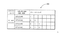
2値化ステップにおいて、所与の非2値シンタックス要素が一意的にビン・ストリング(bin string)と呼ばれる2値シーケンスにマッピングされる。この処理は、シンボルを可変長符号に変換する処理と同様であるが、2値符号がさらに符号化される。図2Aを参照すると、Pスライスにおけるシンタックス要素sub_mb_typeのための符号モードとモード・インデックスとの間のマッピングが概ね参照符号200によって示されている。モードは、0から3にインデックスが付けられる。即ち、P_L0_8×8のインデックス値は、0であり、P_L08×4のインデックス値は、1であり、P_0_4×8のインデックス値は、2であり、P_L0_4×4のインデックス値は、3である。sub_mb_type0は、発生頻度が高いことが予期され、1ビットのビン・ストリングに変換され、sub_mb_type2および3は、発生頻度が低いことが予期され、3ビットのビン・ストリングに変換される。2値化処理は、固定されており、予期される挙動とは異なるモード選択に適応することができない。
In the binarization step, a given non-binary syntax element is uniquely mapped to a binary sequence called a bin string. This process is similar to the process of converting a symbol into a variable length code, but a binary code is further encoded. Referring to FIG. 2A, the mapping between code mode and mode index for the syntax element sub_mb_type in the P slice is indicated generally by the
同様に、限定するものではないが、mb_typeおよびイントラ予測モードを含む他のモードのための符号化処理もまた、MPEG−4 AVC規格にでは、固定されている。従って、MPEG−4 AVC規格は、ビデオ信号の動的な性質を捉えることができない。そこで、各モードを符号化し、符号化効率を向上させるための適応型の方法を設計する必要性が高い。従って、大抵の現代のビデオ符号化規格および勧告と同様に、MPEG−4AVC 規格は、様々な符号化モードを用いて空間ドメインおよび時間ドメイン内の相関を効率的に減少させる。しかしながら、これらのビデオ規格および勧告は、定義済の固定された圧縮方法を用いてブロック・タイプ(パーティション)および予測モードを符号化し、これらを実際のビデオ・コンテンツに一致させる際の適応性を欠くものである。 Similarly, encoding processes for other modes, including but not limited to mb_type and intra prediction modes, are also fixed in the MPEG-4 AVC standard. Therefore, the MPEG-4 AVC standard cannot capture the dynamic nature of video signals. Therefore, it is highly necessary to design an adaptive method for encoding each mode and improving the encoding efficiency. Thus, as with most modern video coding standards and recommendations, the MPEG-4 AVC standard effectively reduces correlation in the spatial and temporal domains using various coding modes. However, these video standards and recommendations lack the adaptability in encoding block types (partitions) and prediction modes using predefined fixed compression methods and matching them to the actual video content. Is.
従来技術のこれらの欠点および短所、さらに、その他の欠点および短所は、適応型のモード・ビデオ符号化および復号のための方法および装置に関する本願の原理によって対処される。 These shortcomings and shortcomings of the prior art, as well as other shortcomings and shortcomings, are addressed by the present principles relating to methods and apparatus for adaptive mode video encoding and decoding.
本願の原理の一態様によれば、装置が提供され、この装置は、適応化されたモード・マッピング情報を符号化してピクチャのシーケンス内のピクチャの少なくとも一部を符号化するために利用可能なモード・インデックスとモードの各値の間のマッピングを行う符号化器を含む。適応化されたモード・マッピング情報は、シーケンスの1つ以上の実際のパラメータに基づいて適応化されている。 In accordance with one aspect of the present principles, an apparatus is provided that can be used to encode adapted mode mapping information to encode at least a portion of a picture in a sequence of pictures. It includes an encoder that performs mapping between mode index and mode values. The adapted mode mapping information has been adapted based on one or more actual parameters of the sequence.
本願の原理の別の態様によれば、方法が提供され、この方法は、適応化されたモード・マッピング情報を符号化してピクチャのシーケンス内のピクチャの少なくとも一部を符号化するために利用可能なモード・インデックスとモードの各値の間のマッピングを行う符号化ステップを含む。適応化されたモード・マッピング情報は、シーケンスの1つ以上の実際のパラメータに基づいて適応化されている。 According to another aspect of the present principles, a method is provided that can be utilized to encode adapted mode mapping information to encode at least a portion of a picture in a sequence of pictures. A coding step for mapping between a mode index and a mode value. The adapted mode mapping information has been adapted based on one or more actual parameters of the sequence.
本願の原理のさらに別の態様によれば、装置が提供され、この装置は、適応化されたモード・マッピング情報を復号してピクチャのシーケンス内のピクチャの少なくとも一部を復号するために利用可能なモード・インデックスとモードの各値の間のマッピングを行う復号器を含む。適応化されたモード・マッピング情報は、シーケンスの1つ以上の実際のパラメータに応じて適応化されている。 According to yet another aspect of the present principles, an apparatus is provided that can be utilized to decode adapted mode mapping information to decode at least a portion of a picture in a sequence of pictures. A decoder that performs mapping between each mode value and each mode value. The adapted mode mapping information is adapted according to one or more actual parameters of the sequence.
本願の原理のさらに別の態様によれば、方法が提供され、この方法は、適応化されたモード・マッピング情報を復号してピクチャのシーケンス内のピクチャの少なくとも一部を復号するために利用可能なモード・インデックスとモードの各値の間のマッピングを行う復号ステップを含む。適応化されたモード・マッピング情報は、シーケンスの1つ以上の実際のパラメータに応じて適応化されている。 In accordance with yet another aspect of the present principles, a method is provided that can be utilized to decode adaptive mode mapping information to decode at least a portion of a picture in a sequence of pictures. A decoding step for mapping between a mode index and a mode value. The adapted mode mapping information is adapted according to one or more actual parameters of the sequence.
本願の原理のこれらの態様、特徴、および利点、さらに、その他の態様、特徴、および利点は、添付の図面と併せて読まれるべき、以下の例示的な実施の形態の詳細な説明によって明らかになるであろう。 These aspects, features, and advantages of the present principles, as well as other aspects, features, and advantages, will be apparent from the following detailed description of exemplary embodiments, which should be read in conjunction with the accompanying drawings. It will be.
本願の原理は、以下の例示的な図面に従ってより良好に理解されるであろう。 The principles of the present application will be better understood according to the following exemplary drawings.
本願の原理は、適応型のモード・ビデオ符号化および復号を行うための方法および装置に関する。 The present principles relate to a method and apparatus for performing adaptive mode video encoding and decoding.
本説明は、本願の原理を例示するものである。従って、本明細書において明示的に記載、または図示されていなくとも、当業者が本願の原理を実施する様々な構成を企図することが可能であり、このような構成が本願の精神および範囲の中に包含されることが理解できるであろう。 This description illustrates the principles of the present application. Accordingly, it will be apparent to those skilled in the art that various configurations of implementing the principles of the present application may be contemplated, and such configurations are within the spirit and scope of the present application, even if not explicitly described or illustrated herein. It will be understood that they are encompassed within.
本明細書に記載された全ての例および条件付の文言は、本願の原理を読者が理解するのを助けるための教示目的のものであり、発明者によって寄与された概念は、技術を発展させるものであり、このような具体的に記載された例や条件に限定されるように解釈されるべきではない。 All examples and conditional language described herein are for instructional purposes to assist the reader in understanding the principles of the present application, and the concepts contributed by the inventor advance the technology. And should not be construed as limited to such specifically described examples or conditions.
また、本明細書における本発明の原理、態様、および、実施の形態についての全ての記載、さらに、その特定の例は、構造的な均等物、機能的な均等物の双方を包含するように意図したものである。さらに、このような均等物は、現在公知の均等物だけでなく、将来において開発される均等物、即ち、構造に係らず、同一の機能を実行するように開発された全ての要素を包含するように意図されている。 In addition, all the descriptions of the principles, aspects, and embodiments of the present invention in this specification, and specific examples thereof include both structural equivalents and functional equivalents. It is intended. Further, such equivalents include not only presently known equivalents, but also equivalents developed in the future, i.e., all elements developed to perform the same function regardless of structure. Is intended to be.
従って、例えば、当業者であれば、本明細書において示されたブロック図は、本願の原理を実施する回路を例示する概念図であることが理解できよう。同様に、フローチャート、フロー図、状態遷移図、擬似コードなどは、いずれも様々な処理を表すことが理解できよう。これらの処理は、実質的にコンピュータによって読み取り可能な媒体において表すことができ、コンピュータまたはプロセッサにより実行され、このようなコンピュータまたはプロセッサがはっきりと図示されているかどうかに係るものではない。 Thus, for example, those skilled in the art will appreciate that the block diagrams shown herein are conceptual diagrams illustrating circuits that implement the principles of the present application. Similarly, it can be understood that a flowchart, a flow diagram, a state transition diagram, pseudo code, and the like all represent various processes. These processes can be represented in a substantially computer readable medium and are performed by a computer or processor, not depending on whether such a computer or processor is explicitly illustrated.
各図面において示される様々な要素の機能は、専用のハードウェアの使用により提供されてもよく、適切なソフトウェアと関連付けてソフトウェアを実行することが可能なハードウェアの使用によって提供されてもよい。機能がプロセッサによって提供される場合にも、単一の専用プロセッサによって提供されてもよく、単一の共有プロセッサによって提供されてもよく、複数の別個のプロセッサによって提供されてもよく、プロセッサの中に共有されているものがあってもよい。さらに、用語「プロセッサ」または「コントローラ」を明示的に使用した場合であっても、ソフトウェアを実行することが可能なハードウェアのみを意味するように解釈されるべきではなく、限定するものではないが、ディジタル信号プロセッサ(DSP:Digital Signal Processor)・ハードウェア、ソフトウェアを格納する読み出し専用メモリ(ROM:Read-Only Memory)、ランダム・アクセス・メモリ(RAM:Random Access Memory)、および不揮発性の記憶装置を暗黙的に含むことがある。 The functions of the various elements shown in each drawing may be provided through the use of dedicated hardware or may be provided through the use of hardware capable of executing software in association with appropriate software. Even if the functionality is provided by a processor, it may be provided by a single dedicated processor, may be provided by a single shared processor, may be provided by multiple separate processors, There may be something shared with you. Further, the explicit use of the terms “processor” or “controller” should not be construed to mean only hardware capable of executing software, but is not limiting. Digital signal processor (DSP) hardware, read-only memory (ROM) that stores software, random access memory (RAM), and non-volatile memory May contain device implicitly.
また、従来のおよび/または慣習的な他のハードウェアを含むこともある。同様に、図面に示されたどのスイッチも概念的なものに過ぎない。これらの機能はプログラム・ロジックの動作を介して、専用のロジックを介して、プログラム制御と専用のロジックとのインタラクションを介して、または、手動でも実行されることがある。状況に応じて具体的に理解されるように、実施者により、特定の技術を選択可能である。 It may also include other conventional and / or customary hardware. Similarly, any switches shown in the drawings are conceptual only. These functions may be performed through the operation of program logic, through dedicated logic, through interaction between program control and dedicated logic, or manually. A specific technique can be selected by the practitioner so as to be specifically understood according to the situation.
請求の範囲において、特定の機能を実施するための手段として表現されたいずれの要素も、この機能をどのような方法で実行するものも包含するように意図している。例えば、a)機能を実行する回路要素を組み合わせたもの、または、b)形態に関わらず、ソフトウェア、つまり、ファームウェア、マイクロコード等を含み、機能を実施するためにソフトウェアを実行する適当な回路と組み合わせたものも包含する。このような請求の範囲によって定義される本願の原理は、請求項に記載された様々な手段によって提供される機能が請求の範囲の要件として、組み合わせられ、まとめられている事実に基づいたものである。従って、このような機能を提供することが可能な手段はどのようなものであっても、本願において示されているものと均等であるとみなされる。 In the claims, any element expressed as a means for performing a specified function is intended to encompass any function that performs that function. For example, a) a combination of circuit elements that perform a function, or b) regardless of form, including software, i.e. firmware, microcode, etc., and a suitable circuit that executes the software to perform the function Combinations are also included. The principles of the present application defined by such claims are based on the fact that the functions provided by the various means recited in the claims are combined and summarized as requirements of the claims. is there. Accordingly, any means capable of providing such functionality is considered equivalent to that shown in this application.
明細書において、本願の原理の「一実施の形態」、「実施の形態」、または、この類の表現が言及されている場合、これは、実施の形態に関して記載される特定の特徴事項、構造、特性などが本願の原理の少なくとも1つの実施の形態に含まれることを意味する。従って、明細書全体に渡って様々な箇所に存在する文言「一実施の形態においては」、「実施の形態においては」、または、この類の表現は、必ずしも、全てが同一の実施の形態について言及するものではない。 In the specification, references to “one embodiment”, “embodiments”, or similar expressions to the principles of the present application, refer to specific features, structures described with respect to the embodiments. , Characteristics and the like are included in at least one embodiment of the present principles. Accordingly, the phrases "in one embodiment," "in an embodiment," or such phrases appearing in various places throughout the specification are not necessarily all referring to the same embodiment. It is not mentioned.
「/(スラッシュ)」、「および/または」、さらに、「〜のうちの少なくとも一方(〜のうちの少なくとも1つ)」の使用は、例えば、「A/B」、「Aおよび/またはB」、「AおよびBのうちの少なくとも一方」の場合、1番目に列挙されたオプション(A)のみの選択、2番目に列挙されたオプション(B)のみの選択、または、両方のオプション(AおよびB)の選択を包含するものと意図されている。別の例として、「A、B、および/またはC」、さらに、「A、B、およびCのうちの少なくとも1つ」の場合、このような文言は、1番目に列挙されたオプション(A)のみの選択、2番目に列挙されたオプション(B)のみの選択、3番目に列挙されたオプション(C)のみの選択、1番目および2番目に列挙されたオプション(AおよびB)のみの選択、1番目および3番目に列挙されたオプション(AおよびC)のみの選択、2番目および3番目に列挙されたオプション(BおよびC)のみの選択、または、全ての3つのオプション(A、B、およびC)の選択を包含するものと意図されている。列挙された数の項目の分だけ、このことが拡張されることは、当該技術分野、さらに、関連する技術分野における通常の技術知識を有するものであれば容易に理解できるであろう。 The use of “/ (slash)”, “and / or” and “at least one of (at least one of)” includes, for example, “A / B”, “A and / or B”. ”,“ At least one of A and B ”, selecting only the first listed option (A), selecting only the second listed option (B), or both options (A And B) are intended to be included. As another example, in the case of “A, B, and / or C”, and “at least one of A, B, and C”, such language is the first listed option (A ) Only selection, only the second enumerated option (B) selection, only the third enumerated option (C) selection, only the first and second enumerated options (A and B) Select, select only the first and third enumerated options (A and C), select only the second and third enumerated options (B and C), or all three options (A, It is intended to encompass the selection of B and C). It will be readily understood by those having ordinary technical knowledge in the technical field and related technical fields that this is expanded by the number of items listed.
さらに、本明細書において、本願の原理の1つ以上の実施の形態は、MPEG−4 AVC規格に関して記載されているが、本願の原理は、この規格のみに限定されるものではない。従って、本願の原理は、本願の原理の精神を逸脱することなく、MPEG−4 AVC規格の拡張版を含む、他のビデオ符号化規格、勧告およびその拡張版にも利用することができる。 Furthermore, although one or more embodiments of the present principles are described herein with reference to the MPEG-4 AVC standard, the present principles are not limited to this standard alone. Thus, the principles of the present application can be used for other video coding standards, recommendations, and extensions thereof, including extended versions of the MPEG-4 AVC standard, without departing from the spirit of the principles of the present application.
本明細書において使用される「ハイレベル・シンタックス」は、マクロブロック・レイヤーよりも階層的に上位に位置するビットストリームに存在するシンタックスを意味する。例えば、本明細書において使用されるハイレベル・シンタックスは、限定するものではないが、スライス・ヘッダ・レベル、補助拡張情報(SEI:Supplemental Enhancement Information)レベル、ピクチャ・パラメータ・セット(PPS: Picture Parameter Set)・レベル、シーケンス・パラメータ・セット(SPS: Sequence Parameter Set)・レベル、さらに、ネットワーク抽象化層(NAL:Network Abstraction Layer)ユニット・ヘッダ・レベルでのシンタックスを意味する場合がある。 As used herein, “high level syntax” refers to syntax that exists in a bitstream that is hierarchically above the macroblock layer. For example, the high-level syntax used herein includes, but is not limited to, a slice header level, a supplemental enhancement information (SEI) level, a picture parameter set (PPS). It may mean syntax at the Parameter Set (Sequence Parameter Set) level, the Sequence Parameter Set (SPS) level, and the Network Abstraction Layer (NAL) unit header level.
上述したように、本願の原理は、適応型のモード・ビデオ符号化および復号を行うための方法および装置に関する。 As described above, the present principles relate to a method and apparatus for performing adaptive mode video encoding and decoding.
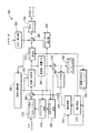
図3を参照すると、本願の原理が適用される例示的なビデオ符号化器が概ね参照符号300によって示されている。 Referring to FIG. 3, an exemplary video encoder to which the present principles are applied is indicated generally by the reference numeral 300.
ビデオ符号化器300は、結合器385の非反転入力と信号通信する出力を有するフレーム順序付けバッファ310を含む。結合器385の出力は、変換器/量子化器325の第1の入力と信号通信するように結合されている。変換器/量子化器325の出力は、エントロピー符号化器345の第1の入力と、逆変換器/逆量子化器350の第1の入力と信号通信するように結合されている。エントロピー符号化器345の出力は、結合器390の第1の非反転入力と信号通信するように結合されている。結合器390の出力は、出力バッファ335の第1の入力と信号通信するように結合されている。
Video encoder 300 includes a
符号化器コントローラ305の出力は、ピクチャ・タイプ決定モジュール315の入力と、マクロブロック・タイプ(MBタイプ)決定モジュール320の第1の入力と、変換器/量子化器325の第2の入力と、シーケンス・パラメータ・セット(SPS:Sequence Parameter Set)/ピクチャ・パラメータ・セット(PPS:Picture Parameter Set)挿入器340の入力と信号通信するように結合されている。
The output of the
SEI挿入器330の出力は、結合器390の第2の非反転入力と信号通信するように結合されている。
The output of
ピクチャ・タイプ決定モジュール315の第1の出力は、フレーム順序付けバッファ310の第3の入力と信号通信するように結合されている。ピクチャ・タイプ決定モジュール315の第2の出力は、マクロブロック・タイプ決定モジュール320の第2の入力と信号通信するように結合されている。
A first output of the picture
シーケンス・パラメータ・セット(SPS:Sequence Parameter Set)/ピクチャ・パラメータ・セット(PPS:Picture Parameter Set)挿入器340の出力は、結合器390の第3の非反転入力と信号通信するように結合されている。
The output of a sequence parameter set (SPS) / picture parameter set (PPS)
逆変換器/逆量子化器350の出力は、結合器319の第1の非反転入力と信号通信するように結合されている。結合器319の出力は、イントラ予測モジュール360の第1の入力と、デブロッキング・フィルタ365の第1の入力と信号通信するように結合されている。デブロッキング・フィルタ365の出力は、参照ピクチャ・バッファ380の入力と信号通信するように結合されている。参照ピクチャ・バッファ380の出力は、動き推定器375の第2の入力と、動き補償器370の第1の入力と信号通信するように結合されている。動き推定器375の第1の出力は、動き補償器370の第2の入力と信号通信するように結合されている。動き推定器375の第2の出力は、エントロピー符号化器345の第2の入力と信号通信するように結合されている。
The output of inverse transformer /
動き補償器370の出力は、スイッチ397の第1の入力と信号通信するように結合されている。イントラ予測モジュール360の出力は、スイッチ397の第2の入力と信号通信するように結合されている。マクロブロック・タイプ決定モジュール320の出力は、スイッチ397の第3の入力と信号通信するように結合されている。スイッチ397の第3の入力は、スイッチの(制御入力、即ち、第3の入力と比較される)「データ」入力が、動き補償器370またはイントラ予測モジュール360によって提供されるかどうかを判定する。スイッチ397の出力は、結合器319の第2の非反転入力および結合器385の第2の非反転入力と信号通信するように結合されている。出力バッファ335の第2の出力は、符号化器コントローラ305の入力と信号通信するように結合されている。
The output of
フレーム順序付けバッファ310の第1の入力は、符号化器100の入力として、入力ピクチャを受信するために利用可能である。さらに、補助拡張情報(SEI:Supplemental Enhancement Information)挿入器330の入力は、符号化器300の入力として、メタデータを受信するために利用可能である。出力バッファ335の出力は、符号化器300の出力として、ビットストリームを出力するために利用可能である。
A first input of the
図4を参照すると、本願の原理が適用される例示的なビデオ復号器が概ね参照符号400によって示されている。
Referring to FIG. 4, an exemplary video decoder to which the present principles are applied is indicated generally by the
ビデオ復号器400は、エントロピー復号器445の第1の入力と信号通信するように結合された出力を有する入力バッファ410を含む。エントロピー復号器445の第1の出力は、逆変換器/逆量子化器450の第1の入力と信号通信するように結合されている。逆変換器/逆量子化器450の出力は、結合器425の第2の非反転入力と信号通信するように結合されている。結合器425の出力は、デブロッキング・フィルタ465の第2の入力と、イントラ予測モジュール460の第1の入力と信号通信するように結合されている。デブロッキング・フィルタ465の第2の出力は、参照ピクチャ・バッファ480の第1の入力と信号通信するように結合されている。参照ピクチャ・バッファ480の出力は、動き補償器470の第2の入力と信号通信するように結合されている。
エントロピー復号器445の第2の出力は、動き補償器470の第3の入力と、デブロッキング・フィルタ465の第1の入力と信号通信するように結合されている。エントロピー復号器445の第3の出力は、復号器コントローラ405の入力と信号通信するように結合されている。復号器コントローラ405の第1の出力は、エントロピー復号器445の第2の入力と信号通信するように結合されている。復号器コントローラ405の第2の出力は、逆変換器/逆量子化器450の第2の入力と信号通信するように結合されている。復号器コントローラ405の第3の出力は、デブロッキング・フィルタ465の第3の入力と信号通信するように結合されている。復号器コントローラ405の第4の出力は、イントラ予測モジュール460の第2の入力と、動き補償器470の第1の入力と、参照ピクチャ・バッファ480の第2の入力と信号通信するように結合されている。
A second output of
動き補償器470の出力は、スイッチ497の第1の入力と信号通信するように結合されている。イントラ予測モジュール460の出力は、スイッチ497の第2の入力と信号通信するように結合されている。スイッチ497の出力は、結合器425の第1の非反転入力と信号通信するように結合されている。
The output of
入力バッファ410の入力は、復号器400の入力として、入力ビットストリームを受信するために利用可能である。デブロッキング・フィルタ465の第1の出力は、復号器400の出力として、出力ピクチャを出力するために利用可能である。
The input of the
よって、本願の原理に従って、適応型のモード・ビデオ符号化および復号を行う方法および装置を提供する。適応型のモードの使用により、符号化効率の改善が実現する。一実施の形態においては、モードとモード・インデックスとの間で適応化を行い、モードを符号化する際に必要となるビット数を減少させる。一実施の形態においては、符号長が短くなるインデックス値を高い頻度で発生するモードに対して設定することにより、符号化効率を向上させる。 Thus, in accordance with the principles of the present application, a method and apparatus for adaptive mode video encoding and decoding is provided. Improved coding efficiency is achieved through the use of an adaptive mode. In one embodiment, adaptation is performed between the mode and the mode index to reduce the number of bits required to encode the mode. In one embodiment, the encoding efficiency is improved by setting an index value that shortens the code length for a mode that occurs frequently.
図2Bを参照すると、図2Aにおいて例として挙げられたシンボルsub_mb_typeについて、符号化モードとモード・インデックスとの間の代替的なマッピングが概ね参照符号250によって表されている。この代替的なマッピング250では、最小のブロック・サイズ(即ち、4×4)は、最小のインデックス(即ち、0)を有するため、その符号語長は最小となる(即ち、1)。1つの特定の適応型のモード符号化方法は、モード統計に依存して、図2Aおよび図2Bのこれらの2つのマッピング・テーブルの間の選択を行うことである。P_L0_8×8モードが有力である(優位にある)場合には、図2Aのテーブルが選択される。P_L0_4×4モードが有力である(優位にある)場合には、図2Bのテーブルが選択される。
Referring to FIG. 2B, for the symbol sub_mb_type exemplified in FIG. 2A, an alternative mapping between coding mode and mode index is generally represented by
実施例1
図5を参照すると、ビデオ符号化器における適応型のモード・符号化を導出するための例示的な方法が概ね参照符号500によって示されている。方法は、制御を機能ブロック520に受け渡す開始ブロック510を含む。機能ブロック520は、符号化セットアップ(オプションとして、オペレータのアシスタンスを伴う場合がある)を実行し、制御をループ端ブロック530に受け渡す。ループ端ブロック530は、ピクチャjのループを実行し、制御を機能ブロック540に受け渡す。ここで、j=1,・・・,#である(シンボル「♯」は、単語「数(number)」を表す)。機能ブロック540は、ピクチャjを符号化し、制御を機能ブロック550に受け渡す。機能ブロック550は、1回の反復処理(最初の反復処理である必要はない)の間に、前に符号化したビデオ・コンテンツからのモード・マッピングを導出し、その後、1回以上の後続する反復処理の間に、1回以上モード・マッピングを更新し、オプションとして、1つ以上の条件(例えば、シーンの変化など)に基づいてモード・マッピングのリセット処理を実行し、制御をループ端ブロック560に受け渡す。ループ端ブロック560は、ループを終了し、制御を終了ブロック599に受け渡す。
Example 1
With reference to FIG. 5, an exemplary method for deriving adaptive mode coding in a video encoder is indicated generally by the
方法500において、モードとモード・インデックスとの間のマッピングが前に符号化されたビデオ・コンテンツから導出される。例えば、決定ルールは、限定するものではないが、前に符号化されたピクチャにおけるモード使用の頻度、さらに、時間解像度、空間解像度などの他の情報に基づくものとすることができる。勿論、他のパラメータを前に規定されたパラメータ、さらに/または、1つ以上の前に規定されたパラメータの代わりに使用することができる。方法500においては、各ピクチャが符号化された後に適応型のモード・マッピングが更新される。しかしながら、本願の原理は、前述した更新頻度に限定されるものではなく、本願の原理の精神を逸脱することなく、他の更新頻度を使用できることが理解できよう。例えば、更新処理は、ピクチャ群(GOP:Ggroup Of Picture)などの少数のピクチャまたはシーンの後に適用して演算量を低減することができる。モード・マッピングを更新するために、1つ以上の符号化されたピクチャを使用することができる。使用されるべき前の符号化されたピクチャの量は、符号化器および復号器の双方に知られている何らかのルールに基づくものとすることができる。一実施の形態においては、特定のモード・マッピングのリセット処理を導入してマッピング・テーブルをシーンの変更でデフォルトのものにリセットすることができる。
In
図6を参照すると、ビデオ復号器における適応型のモード符号化を導出するための例示的な方法が概ね参照符号600によって示されている。方法は、制御をループ端ブロック620に受け渡す開始ブロック610を含む。ループ端ブロック620は、ピクチャjのループを開始し、制御を機能ブロック630に受け渡す。ここで、j=1,・・・,#である(シンボル「♯」は、単語「数(number)」を表す)。機能ブロック630は、ピクチャjを復号し、制御を機能ブロック640に受け渡す。機能ブロック640は、1回の反復処理(最初の反復処理である必要はない)の間に、前に復号したビデオ・コンテンツからのモード・マッピングを導出し、その後、1回以上の後続する反復処理の間に、1回以上モード・マッピングを更新し、オプションとして、1つ以上の条件(例えば、シーンの変化など)に基づいてモード・マッピングのリセット処理を実行し、制御をループ端ブロック650に受け渡す。ループ端ブロック650は、ループを終了し、処理を終了ブロック699に受け渡す。
With reference to FIG. 6, an exemplary method for deriving adaptive mode coding in a video decoder is indicated generally by the
従って、各ピクチャがブロック630において復号された後、モード・マッピングは、符号化器での処理と同様の処理で更新される。
Thus, after each picture is decoded at
この方法においては、前に符号化されたピクチャから適応型のモード・マッピングが導出される。この方法の多くの利点のうちの1つは、方法がコンテンツに適応し、マッピング情報を伝達する際に余分なシンタックスを必要としない点である。しかしながら、この方法は、マッピングを導出するために符号化器および復号器の側で余分な演算を必要とすることがある。さらに、ビットストリームがエラーを伴う環境で伝送される場合、前に符号化されたピクチャに損傷が発生する場合、マッピングが適切に導出されないことがあり、これにより、復号器が適切に動作しないことがある。 In this method, an adaptive mode mapping is derived from a previously encoded picture. One of the many advantages of this method is that the method adapts to the content and does not require extra syntax when conveying mapping information. However, this method may require extra operations on the encoder and decoder side to derive the mapping. In addition, if the bitstream is transmitted in an error-prone environment, the mapping may not be properly derived if the previously encoded picture is damaged, which prevents the decoder from operating properly. There is.
実施の形態2
別の実施の形態においては、マッピング情報がシンタックス内に具体的に示され、ビットストリームで伝送される。この方法においては、適応型のモード・マッピングは、符号化処理の前または間に導出することができる。例えば、相異なる空間解像度で符号化されたものからのトレーニング・データに従って、モード・マッピング・テーブルを空間解像度の範囲で作成することができる。次に、マッピングは、シーケンス・レベル、ピクチャ・レベル、スライス・レベルなどで符号化される。
In another embodiment, the mapping information is specifically indicated in the syntax and transmitted in a bitstream. In this method, adaptive mode mapping can be derived before or during the encoding process. For example, a mode mapping table can be created in a range of spatial resolutions according to training data from those encoded at different spatial resolutions. The mapping is then encoded at the sequence level, picture level, slice level, etc.
図7を参照すると、ビデオ符号化器においてシーケンス・レベルで適応型のモード符号化を適用する例示的な方法が概ね参照符号700によって示されている。方法700は、結果として生じたビットストリームにモード・マッピングを埋め込む。方法700は、制御を機能ブロック720に受け渡す開始ブロック710を含む。機能ブロック720は、符号化セットアップ(オプションとして、オペレータのアシスタンスを伴う場合がある)を実行し、制御を機能ブロック730に受け渡す。機能ブロック730は、例えば、トレーニング・データに基づき、モード・マッピングを導出し(このトレーニング・データは、例えば、相異なる空間解像度などで符号化したものに基づく)、制御を機能ブロック740に受け渡す。機能ブロック740は、例えば、結果として生じたビットストリームまたは副情報において伝送されるシンタックスの中のモード・マッピング情報を示すことによって、モード・マッピングを符号化し、制御をループ端ブロック750に受け渡す。ループ端ブロック750は、ピクチャjのループを実行し、制御を機能ブロック760に受け渡す。ここで、j=1,・・・,#である(シンボル「♯」は、単語「数(number)」を表す)。機能ブロック760は、ピクチャjを符号化し、制御をループ端ブロック770に受け渡す。ループ端ブロック770は、制御を終了ブロック799に受け渡す。
Turning to FIG. 7, an exemplary method for applying adaptive mode coding at the sequence level in a video encoder is indicated generally by the
図8を参照すると、ビデオ復号器においてシーケンス・レベルで適応型のモード符号化を導出するための例示的な方法が概ね参照符号800によって示されている。方法800は、モード・マッピングが埋め込まれている受信したビットストリームのパージングを行う。方法800は、制御を機能ブロック820に受け渡す開始ブロック810を含む。機能ブロック820は、モード・マッピングを復号し、制御をループ端ブロック830に受け渡す。ループ端ブロック830は、ピクチャjのループを実行し、制御を機能ブロック840に受け渡す。ここで、j=1,・・・,#である(シンボル「♯」は、単語「数(number)」を表す)。機能ブロック840は、ピクチャjを復号し、制御をループ端ブロック850に受け渡す。ループ端ブロック850は、ループを終了し、制御を終了ブロック899に受け渡す。
With reference to FIG. 8, an exemplary method for deriving adaptive mode coding at the sequence level in a video decoder is indicated generally by the
上述した方法700および800においては、モード・マッピング情報がビットストリーム内で具体的に送信される。これにより、このような情報を復号器は、前に符号化されたピクチャを参照することなく取得することができ、伝送エラーに対してよりロバストな(堅牢な)ビットストリームを提供する。しかしながら、モード・マッピング情報を送信する際により大きなオーバヘッドビットのコストを有する。
In the
実施の形態3
別の実施の形態においては、マッピング情報がシンタックス内でも示されており、ビットストリームで伝送される。実施の形態2の場合とは異なり、前に符号化されたピクチャまたは今回符号化されたピクチャに基づいて、マッピング・テーブルを符号化/復号処理の間に作成することができる。例えば、ピクチャを符号化する前に、モード・マッピング・テーブルが作成され、シンタックス内で示される。符号化処理の間にモード・マッピング・テーブルを更新し続けることができる。モード・マッピング・テーブルは、前に符号化されたピクチャ情報に基づいて作成されるか、さらに/または、何らかのモード・マッピング・テーブルのセットおよび/または今回符号化されたピクチャの異なる/部分的な符号化パスから選択される。さらに、マッピング・テーブルは、例えば、限定するものではないが、平均や分散など、符号化されたピクチャまたはシーケンスの統計に基づいて作成することができる。
In another embodiment, the mapping information is also shown in the syntax and is transmitted in a bitstream. Unlike the case of the second embodiment, the mapping table can be created during the encoding / decoding process based on the previously encoded picture or the current encoded picture. For example, before encoding a picture, a mode mapping table is created and shown in the syntax. The mode mapping table can continue to be updated during the encoding process. The mode mapping table is created based on previously encoded picture information and / or some set of mode mapping tables and / or different / partial of the current encoded picture Selected from the encoding pass. Furthermore, the mapping table can be created based on the statistics of the encoded picture or sequence, such as, but not limited to, average or variance.
図9を参照すると、ビデオ符号化器における適応型のモード・マッピングを行う例示的な方法が概ね参照符号900によって示されている。方法900は、制御を機能ブロック920に受け渡す開始ブロック910を含む。機能ブロック920は、符号化セットアップを実行し、制御をループ端ブロック930に受け渡す。ループ端ブロック930は、ピクチャjのループを実行し、制御を機能ブロック940に受け渡す。ここで、j=1,・・・,#である(シンボル「♯」は、単語「数(number)」を表す)。機能ブロック940は、前に符号化されたピクチャおよび/または今回符号化されたピクチャjに基づく、さらに/または、モード・マッピングのセット、1つ以上のピクチャまたはシーケンスの統計値などから選択されるモード・マッピングを取得し、制御を機能ブロック950に受け渡す。機能ブロック950は、ピクチャjを符号化し、制御を機能ブロック960に受け渡す。機能ブロック960は、(符号化されるべき)1つ以上の将来のピクチャについて、例えば、前に符号化されたピクチャおよび/または今回符号化されたピクチャjに基づく、さらに/または、1つ以上のピクチャまたはシーケンスの統計値などから選択される、モード・マッピングを作成し(このモード・マッピングは、独立したモード・マッピングまたは前のモード・マッピングを更新したものである)、制御を機能ブロック970に受け渡す。機能ブロック970は、モード・マッピングを符号化し、制御を機能ブロック975に受け渡す。機能ブロック975は、結果として生ずるビットストリームで伝送されるシンタックス内のマッピング情報を示し、制御をループ端ブロック980に受け渡す。ループ端ブロック980は、ループを終了し、制御を終了ブロック999に受け渡す。
Referring to FIG. 9, an exemplary method for performing adaptive mode mapping in a video encoder is indicated generally by the
方法900の一実施の形態においては、ブロック940は、前に符号化されたピクチャからモード・マッピングを取得する。モード・マッピングを導出するために使用される前に符号化されたピクチャは、前の符号化パスにおいて符号化されたピクチャと同じものでもよいし、その前に符号化された他のピクチャであってもよい。
In one embodiment of
図10を参照すると、ビデオ復号器における適応型のモード・マッピングのための例示的な方法が概ね参照符号1000によって示されている。方法1000は、制御をループ端ブロック1020に受け渡す開始ブロック1010を含む。ループ端ブロック1020は、ピクチャjのループを実行し、制御を機能ブロック1030に受け渡す。ここで、j=1,・・・,#である(シンボル「♯」は、単語「数(number)」を表す)。機能ブロック1030は、モード・マッピングをパージングし、制御を機能ブロック1040に受け渡す。機能ブロック1040は、ピクチャjを復号し、制御をループ端ブロック1050に受け渡す。ループ端ブロック1050は、ループを終了し、制御を終了ブロック1099に受け渡す。
Referring to FIG. 10, an exemplary method for adaptive mode mapping in a video decoder is indicated generally by the
このアプローチにおいては、モード・マッピングは、符号化処理の間に適応的に更新され、これは、ビデオ・シーケンスの非定常物を捉えるのに有用である。モード・マッピング・テーブルは、ビットストリーム内において明示的に送信され、符号化処理および復号処理をよりロバストな(堅牢な)ものにする。 In this approach, the mode mapping is adaptively updated during the encoding process, which is useful for capturing non-stationary objects in the video sequence. The mode mapping table is sent explicitly in the bitstream, making the encoding and decoding processes more robust (robust).
シンタックス
モードとモード・インデックスとの間の適応型のマッピングは、ハイレベル・シンタックスにおいて規定することができる。一実施の形態では、本願の原理に従って使用するINTRAフレームのためのシンタックスをどのように定義するかについて、例を示す。MPEG−4 AVC規格において、決まったマッピングが、符号化器側と復号器側でのデフォルトのマッピングとして使用される。我々の提案する方法は、シーケンス・パラメータ・セット、または、ピクチャ・パラメータ・セットを介して他のマッピングを使用するフレキシビリティを提供する。シーケンス・パラメータ・セットおよびピクチャ・パラメータ・セットにおけるシンタックスの例が表1および表2にそれぞれ示されている。本願の原理の精神を逸脱することなく、様々なレベルで各インター・フレームおよび他のシンタックス要素に対して同様のシンタックスの変更を適用することができる。

シーケンス・パラメータ・セットにおけるシンタックスを以下に示す。
seq_mb_type_adaptation_present_flag equal to 1(seq_mb_type_adaptation_present_flagが1である)は、シーケンス・パラメータ・セット内に適応型のモード・マッピングが存在することを規定する。seq_mb_type_adaptation_present_flag equal to 0(seq_mb_type_adaptation_present_flagが0である)は、シーケンス・パラメータ・セット内に適応型のモード・マッピングが存在しないことを規定する。デフォルトのマッピングが使用される。
The syntax for the sequence parameter set is shown below.
seq_mb_type_adaptation_present_flag equal to 1 (seq_mb_type_adaptation_present_flag is 1) specifies that there is an adaptive mode mapping in the sequence parameter set. seq_mb_type_adaptation_present_flag equal to 0 (seq_mb_type_adaptation_present_flag is 0) specifies that there is no adaptive mode mapping in the sequence parameter set. The default mapping is used.
mb_type_adaptive_index[i]は、新たなモード・インデックスの値を規定する。ここで、iは、デフォルト・マッピングのインデックスである。 mb_type_adaptive_index [i] defines a new mode index value. Here, i is an index of default mapping.
seq_intra4×4_prediction_mode_adaptation_present_flag equal to 1(seq_intra4×4_prediction_mode_adaptation_present_flagが1である)は、シーケンス・パラメータ・セット内に適応型のINTRA4×4およびINTRA8×8予測モード・マッピングが存在することを規定する。seq_intra4×4_prediction_mode_adaptation_present_flag equal to 0(seq_intra4×4_prediction_mode_adaptation_present_flagが0である)は、シーケンス・パラメータ・セット内に適応型のINTRA4×4およびINTRA8×8予測モード・マッピングが存在しないことを規定する。デフォルトのマッピングが使用される。 seq_intra4 × 4_prediction_mode_adaptation_present_flag equal to 1 (seq_intra4 × 4_prediction_mode_adaptation_present_flag is A in the sequence parameter IN and the mode A is in the sequence parameter IN. seq_intra4 × 4_prediction_mode_adaptation_present_flag equal to 0 (seq_intra4 × 4_prediction_mode_adaptation_present_flag is 8 in the sequence parameter set and IN is in the sequence parameter set TR) The default mapping is used.
Intra4×4_prediction_mode_adaptive_index[i]は、新たなINTRA4×4およびINTRA8×8モード・インデックスの値を規定する。ここで、iは、デフォルト・マッピングのインデックスである。 Intra4 × 4_prediction_mode_adaptive_index [i] defines the new INTRA4 × 4 and INTRA8 × 8 mode index values. Here, i is an index of default mapping.
seq_intra16×16_prediction_mode_adaptation_present_flag equal to 1(seq_intra16×16_prediction_mode_adaptation_present_flagが1である)は、シーケンス・パラメータ・セット内に適応型のINTRA16×16予測モード・マッピングが存在することを規定する。seq_intra16×16_prediction_mode_adaptation_present_flag equal to 0(seq_intra16×16_prediction_mode_adaptation_present_flagが0である)は、シーケンス・パラメータ・セット内に適応型のINTRA16×16予測モード・マッピングが存在しないことを規定する。デフォルト・マッピングが使用される。 seq_intra16 × 16_prediction_mode_adaptation_present_flag equal to 1 (seq_intra16 × 16_prediction_mode_adaptation_present_flag is 16 in the sequence parameter set TR in which the type A is in the sequence parameter set TR) seq_intra16 × 16_prediction_mode_adaptation_present_flag equal to 0 (seq_intra16 × 16_prediction_mode_adaptation_present_flag is 0 in the sequence parameter set TR) Default mapping is used.
Intra16×16_prediction_mode_adaptive_index[i]は、新たなINTRA16×16モード・インデックスの値を規定する。ここで、iは、デフォルト・マッピングのインデックスである。 Intra16 × 16_prediction_mode_adaptive_index [i] defines the value of the new INTRA16 × 16 mode index. Here, i is an index of default mapping.
ピクチャ・パラメータ・セットにおけるシンタックスを以下に示す。
pic_mb_type_adaptation_present_flag equal to 1(pic_mb_type_adaptation_present_flagが1である)は、ピクチャ・パラメータ・セット内に適応型のモード・マッピングが存在することを規定する。pic_mb_type_adaptation_present_flag equal to 0(pic_mb_type_adaptation_present_flagが0である)は、ピクチャ・パラメータ・セット内に適応型のモード・マッピングが存在しないことを規定する。デフォルトのマッピングが使用される。
The syntax for the picture parameter set is shown below.
pic_mb_type_adaptation_present_flag equal to 1 (pic_mb_type_adaptation_present_flag is 1) specifies that there is an adaptive mode mapping in the picture parameter set. pic_mb_type_adaptation_present_flag equal to 0 (pic_mb_type_adaptation_present_flag is 0) specifies that there is no adaptive mode mapping in the picture parameter set. The default mapping is used.
mb_type_adaptive_index[i]は、新たなモード・インデックスの値を規定する。ここで、iは、デフォルト・マッピングのインデックスである。 mb_type_adaptive_index [i] defines a new mode index value. Here, i is an index of default mapping.
pic_intra4×4_prediction_mode_adaptation_present_flag equal to 1(pic_intra4×4_prediction_mode_adaptation_present_flagが1である)は、ピクチャ・パラメータ・セット内に適応型のINTRA4×4およびINTRA8×8の予測モード・マッピングが存在することを規定する。pic_intra4×4_prediction_mode_adaptation_present_flag equal to 0(pic_intra4×4_prediction_mode_adaptation_present_flagが0である)は、ピクチャ・パラメータ・セット内に適応型のINTRA4×4およびINTRA8×8のモード・マッピングが存在しないことを規定する。デフォルトのマッピングが使用される。 pic_intra4 × 4_prediction_mode_adaptation_present_flag equal to 1 (pic_intra4 × 4_prediction_mode_adaptation_present_flag is 1 in the picture parameter set TR) pic_intra4 × 4_prediction_mode_adaptation_present_flag equal to 0 (pic_intra4 × 4_prediction_mode_adaptation_present_flag is set to A in the picture parameter set TR is in the picture parameter set TR.) The default mapping is used.
Intra16×16_prediction_mode_adaptive_index[i]は、新たなINTRA16×16モード・インデックスの値を規定する。ここで、iは、デフォルト・マッピングのインデックスである。 Intra16 × 16_prediction_mode_adaptive_index [i] defines the value of the new INTRA16 × 16 mode index. Here, i is an index of default mapping.
pic_intra16×16_prediction_mode_adaptation_present_flag equal to 1(pic_intra16×16_prediction_mode_adaptation_present_flagが1である)は、ピクチャ・パラメータ・セット内に適応型のINTRA16×16予測モード・マッピングが存在することを規定する。pic_intra16×16_prediction_mode_adaptation_present_flag equal to 0(pic_intra16×16_prediction_mode_adaptation_present_flagが0である)は、ピクチャ・パラメータ・セット内に適応型のINTRA16×16予測モード・マッピングが存在しないことを規定する。デフォルトのマッピングが使用される。 pic_intra16 × 16_prediction_mode_adaptation_present_flag equal to 1 (pic_intra16 × 16_prediction_mode_adaptation_present_flag is 1 in the picture parameter set TR). pic_intra16 × 16_prediction_mode_adaptation_present_flag equal to 0 (pic_intra16 × 16_prediction_mode_adaptation_present_flag is 0 in the picture parameter set TR) The default mapping is used.
Intra16×16_prediction_mode_adaptive_index[i]は、新たなINTRA16×16モード・インデックスの値を規定する。ここで、iは、デフォルト・マッピングのインデックスである。 Intra16 × 16_prediction_mode_adaptive_index [i] defines the value of the new INTRA16 × 16 mode index. Here, i is an index of default mapping.
変形例
この変形例では、INTRAモード・マッピングにどのように適応するかについての別の具体例を提供する。2つのINTRAモード、INTRA4×4およびINTRA8×8が存在することを想定する。さらに、これらの2つのINTRAモードが指数ゴロム(Exp‐Golomb)符号語を用いて符号化されることを想定する。この具定例のために、INTRAモードをSIPタイプ(sip_type)と呼ぶ。
Variant This variant provides another example of how to adapt to INTRA mode mapping. Assume that there are two INTRA modes, INTRA4x4 and INTRA8x8. Further assume that these two INTRA modes are encoded using Exp-Golomb codewords. For this specific example, the INTRA mode is called a SIP type (sip_type).
シンタックス
この具体例のためのシンタックスの変更が表3に示されている。低解像度のビデオのためのマッピングが符号化器および復号器の側でデフォルト・マッピングとして使用される。アプリケーションの中には、他の解像度のためにこのマッピングをデフォルトのマッピングとして使用できるものもある。我々の提案する方法は、シーケンス・パラメータ・セットまたはピクチャ・パラメータ・セットを通じて他のマッピングを使用するフレキシビリティを提供する。表3は、ピクチャ・パラメータ・セットにおけるシンタックスの変更を示す。限定するものではないが、シーケンス・パラメータ・セットを含む他のシンタックスのレベルに同様のシンタックスの変更を適用することができる。
ピクチャ・パラメータ・セットにおけるシンタックスを以下に示す。
sip_type_flag equal to 1(sip_type_flagが1である)は、ピクチャ・パラメータ・セット内に適応型のモード・マッピングが存在することを規定する。sip_type_flag equal to 0(sip_type_flagが0である)は、ピクチャ・パラメータ・セット内に適応型のモード・マッピングが存在しないことを規定する。デフォルトのマッピングが使用される。
The syntax for the picture parameter set is shown below.
sip_type_flag equal to 1 (sip_type_flag is 1) specifies that there is an adaptive mode mapping in the picture parameter set. sip_type_flag equal to 0 (sip_type_flag is 0) specifies that there is no adaptive mode mapping in the picture parameter set. The default mapping is used.
sip_type_index[i]は、新たなモード・インデックスの値を規定する。ここで、iは、デフォルト・マッピングのインデックスである。 sip_type_index [i] defines a new mode index value. Here, i is an index of default mapping.
sip_typeの分布は、低解像度のビデオと高解像度のビデオとで異なるものになると考えることが合理的である。例えば、INTRA4×4は、低解像度のビデオのために選択されることが多く、INTRA8×8は、高解像度のビデオのために選択されることが多い。表4および表5は、低解像度のビデオと高解像度のビデオのそれぞれについて、ピクチャ解像度に基づいたモード・マッピングにどのように適応させるかについて例示している。特に、表4は、sip_type_flag=0であるsip_typeの仕様を示し、表5は、sip_typ_flag=1であるsip_typeの仕様を示している。低解像度ビデオにおいては、INTRA4×4には、0のインデックスが付けられ、INTRA8×8には、1のインデックスが付けられる。sip_type=0(INTRA4×4)は、選択されることがより多くなると見込まれるため、短い符号語を用いて符号化される。さらに、このマッピングは、デフォルト・マッピングとして使用される。高解像度ビデオにおいては、INTRA8×8には、0のインデックスが付けられ、INTRA4×4には、1のインデックスが付けられる。これは、より可能性の高いモードに0のインデックスを付け、短い符号語を用いて符号化することを保証するためである。表6は、モード・インデックスにおける変更を表すために使用される。ここで、iは、デフォルトのモード・インデックスであり、sip_type_index[i]は、新たなモード・インデックスである。特に、表6は、sip_type_flag=1のときのモード・マッピングの例を示している。
本発明の多くの付随する利点/特徴の幾つかについて説明する。これらの幾つかは既に述べた通りのものである。例えば、1つの利点/特徴は、適応化されたモード・マッピング情報を符号化してピクチャのシーケンス内のピクチャの少なくとも一部を符号化するために利用可能なモード・インデックスとモードの各値の間のマッピングを行う符号化器を含む装置である。適応化されるモード・マッピング情報は、シーケンスの1つ以上の実際のパラメータに基づいて適応化されている。 Some of the many attendant advantages / features of the present invention are described. Some of these have already been mentioned. For example, one advantage / feature is between the mode index and the mode values available to encode the adapted mode mapping information to encode at least a portion of the pictures in the sequence of pictures. It is an apparatus including the encoder which performs mapping of. The mode mapping information to be adapted is adapted based on one or more actual parameters of the sequence.
さらに、別の利点/特徴は、上述した符号化器を有する装置であって、ピクチャは、今回符号化されたピクチャであり、実際のパラメータは、シーケンスにおける1つ以上の前に符号化されたピクチャのための符号化情報を含む、この装置である。 Yet another advantage / feature is an apparatus having the above-described encoder, where the picture is a picture that has been encoded this time and the actual parameters have been encoded one or more before in the sequence. This device contains the coding information for a picture.
さらに、別の利点/特徴は、上述したような、ピクチャは、今回符号化されたピクチャであり、実際のパラメータは、シーケンスにおける1つ以上の前に符号化されたピクチャのための符号化情報を含む、符号化器を有する装置であって、符号化情報は、モードの使用頻度、少なくとも1つの空間解像度、および少なくとも1つの時間解像度のうちの少なくとも1つを含む、この装置である。 In addition, another advantage / feature is that, as described above, the picture is the current encoded picture and the actual parameter is the encoding information for one or more previously encoded pictures in the sequence. An apparatus having an encoder, wherein the encoding information includes at least one of mode usage frequency, at least one spatial resolution, and at least one temporal resolution.
さらに、別の利点/特徴は、上述した符号化器を有する装置であって、シーケンスの少なくとも一部は、結果として生ずるビットストリームに符号化され、適応化されたモード・マッピング情報は、結果として生ずるビットストリームにおいて信号送信される、この装置である。 Yet another advantage / feature is an apparatus having the above-described encoder, wherein at least a portion of the sequence is encoded into the resulting bitstream and the adapted mode mapping information results in It is this device that is signaled in the resulting bitstream.
さらに、別の利点/特徴は、上述した符号化器を有する装置であって、適応化されたモード・マッピング情報は、少なくとも1つのハイレベル・シンタックス要素を使用して信号送信される、この装置である。 Yet another advantage / feature is an apparatus having the above-described encoder, wherein the adapted mode mapping information is signaled using at least one high-level syntax element. Device.
さらに、別の利点/特徴は、上述したような、適応化されたモード・マッピング情報は、少なくとも1つのハイレベル・シンタックス要素を使用して信号送信される、符号化器を有する装置であって、スライス・ヘッダ、シーケンス・パラメータ・セット、ピクチャ・パラメータ・セット、ネットワーク抽象化層ユニット・ヘッダ、および補助拡張情報メッセージのうちの少なくとも1つにハイレベル・シンタックス要素が含まれている、この装置である。 Yet another advantage / feature is an apparatus having an encoder, as described above, wherein the adapted mode mapping information is signaled using at least one high-level syntax element. A high level syntax element is included in at least one of a slice header, a sequence parameter set, a picture parameter set, a network abstraction layer unit header, and an auxiliary extension information message, This device.
さらに、別の利点/特徴は、上述した符号化器を有する装置であって、シーケンスの1つ以上のピクチャの符号化の後に適応化されたモード・マッピング情報が更新される、この装置である。 Yet another advantage / feature is an apparatus comprising the above-described encoder, wherein the adapted mode mapping information is updated after encoding one or more pictures of the sequence. .
さらに、別の利点/特徴は、上述した符号化器を有する装置であって、シーケンス内の1つ以上の前に符号化されたピクチャのための符号化情報、シーケンスの少なくとも一部に関連する適応化されたモード・マッピング情報のセットのうちの選択されたサブセット、ピクチャのための1つ以上の部分的な符号化パス、シーケンス内の1つ以上のピクチャの統計、シーケンス内の1つ以上のピクチャの1つ以上の部分の統計、およびシーケンスの統計のうちの少なくとも1つから実際のパラメータが決定される、この装置である。 Yet another advantage / feature is an apparatus having the above-described encoder, which relates to encoding information for one or more previously encoded pictures in the sequence, at least part of the sequence A selected subset of the set of adapted mode mapping information, one or more partial coding passes for a picture, statistics of one or more pictures in a sequence, one or more in a sequence The apparatus in which actual parameters are determined from at least one of statistics of one or more portions of the picture and sequence statistics.
本願の原理のこれらの特徴およびその他の特徴は、関連する分野において通常の知識を有するものであれば、本明細書中の開示内容に基づいて、容易に解明することができるであろう。本願の原理の開示内容は、ハードウェア、ソフトウェア、ファームウェア、特定用途向けプロセッサ、または、これらを組み合わせた様々な形態で実施できることが理解できよう。 These and other features of the present principles may be readily clarified based on the disclosure herein, provided that the person has ordinary knowledge in the relevant field. It will be appreciated that the disclosed principles of the present application may be implemented in various forms, including hardware, software, firmware, application specific processors, or combinations thereof.
より好ましくは、本願の原理の開示内容は、ハードウェアおよびソフトウェアを組み合わせて実施される。さらに、ソフトウェアは、プログラム記憶装置上に現実的に実装されるアプリケーション・プログラムとして実施される。アプリケーション・プログラムは、適切なアーキテクチャからなるマシンにアップロードされ、このマシンによって実行されるようにしてもよい。好ましくは、このマシンは、1つ以上の中央処理装置(CPU)、ランダム・アクセス・メモリ(RAM)、入出力(I/O)インタフェースを有するコンピュータ・プラットフォーム上で実施される。また、コンピュータ・プラットフォームは、オペレーティング・システムおよびマイクロインストラクション・コードを含むようにしてもよい。本明細書中で開示される様々な処理および機能は、マイクロインストラクション・コードの一部を構成するものでもよいし、アプリケーション・プログラムの一部を構成するものであってもよいし、これらを組み合わせたものであってもよいし、CPUによって実行されるものであってもよい。さらに、追加的なデータ記憶装置や印刷機等、コンピュータ・プラットフォームに様々な他の周辺機器を結合するようにしてもよい。 More preferably, the principles disclosed herein are implemented in a combination of hardware and software. Furthermore, the software is implemented as an application program that is actually implemented on a program storage device. The application program may be uploaded to a machine having an appropriate architecture and executed by this machine. Preferably, the machine is implemented on a computer platform having one or more central processing units (CPUs), a random access memory (RAM), and input / output (I / O) interfaces. The computer platform may also include an operating system and microinstruction code. The various processes and functions disclosed in this specification may form part of the microinstruction code, may form part of the application program, or a combination thereof. Or may be executed by a CPU. In addition, various other peripheral devices may be connected to the computer platform such as an additional data storage device and a printing machine.
添付図面に示すシステムの構成要素および方法のステップの幾つかは、好ましくは、ソフトウェアの形態によって実施されるため、システムの構成要素または処理機能ブロック間の実際の結合は、本願の原理をプログラムする方法によって異なる場合があることが理解できよう。本明細書の開示する内容に基づいて、関連する技術における通常の技術知識を有するものであれば、本願の原理の実施の形態または構成、さらに、類似した実施の形態または構成を企図することができるであろう。 Since some of the system components and method steps shown in the accompanying drawings are preferably implemented in software form, the actual coupling between system components or processing functional blocks programs the principles of the present application. It can be understood that it may vary depending on the method. Based on the content disclosed in this specification, an embodiment or configuration of the principle of the present application, or a similar embodiment or configuration may be contemplated as long as the person has ordinary technical knowledge in the related technology. It will be possible.
添付図面を参照して本明細書中で例示的な実施の形態について説明したが、本発明はこれらの実施の形態に厳格に限定されるものではなく、関連技術に関して通常の技術を有する者であれば、本願の原理の範囲または精神を逸脱することなく、様々な変更、改変を施すことが可能であることが理解できるであろう。このような変更、改変は、全て、添付の請求の範囲に定義されたような本願の原理の範囲に含まれるように意図されている。
(付記)
(付記1)
モード・マッピング情報を符号化してピクチャのシーケンス内のピクチャの少なくとも一部を符号化するために利用可能なモード・インデックスとモードの各値の間のマッピングを行う符号化器(300)を含み、
前記モード・マッピング情報は、前記シーケンスの1つ以上の実際のパラメータに応じて適応化される、前記装置。
(付記2)
前記ピクチャは、今回符号化されたピクチャであり、前記実際のパラメータは、前記シーケンスにおける1つ以上の前に符号化されたピクチャのための符号化情報を含む、付記1に記載の装置。
(付記3)
前記符号化情報は、モードの使用頻度、少なくとも1つの空間解像度、および少なくと
も1つの時間解像度のうちの少なくとも1つを含む、付記2に記載の装置。
(付記4)
前記シーケンスの少なくとも一部は、結果として生ずるビットストリームに符号化され、前記適応化されたモード・マッピング情報は、前記結果として生ずるビットストリームにおいて信号送信される、付記1に記載の装置。
(付記5)
前記適応化されたモード・マッピング情報は、少なくとも1つのハイレベル・シンタックス要素を使用して信号送信される、付記1に記載の装置。
(付記6)
スライス・ヘッダ、シーケンス・パラメータ・セット、ピクチャ・パラメータ・セット、ネットワーク抽象化層ユニット・ヘッダ、および補助拡張情報メッセージのうちの少なくとも1つに前記ハイレベル・シンタックス要素が含まれている、付記1に記載の装置。
(付記7)
前記シーケンスの1つ以上のピクチャの符号化の後に前記適応化されたモード・マッピング情報が更新される、付記1に記載の装置。
(付記8)
前記シーケンス内の1つ以上の前に符号化されたピクチャのための符号化情報、前記シーケンスの少なくとも一部に関連する適応化されたモード・マッピング情報のセットのうちの選択されたサブセット、前記ピクチャのための1つ以上の部分的な符号化パス、前記シーケンス内の1つ以上のピクチャの統計、前記シーケンス内の前記1つ以上のピクチャの1つ以上の部分の統計、および前記シーケンスの統計のうちの少なくとも1つから前記実際のパラメータが決定される、付記1に記載の装置。
(付記9)
モード・マッピング情報を符号化してピクチャのシーケンス内のピクチャの少なくとも一部を符号化するために利用可能なモード・インデックスとモードの各値の間のマッピングを行うステップ(740、970)を含み、
前記モード・マッピング情報は、前記シーケンスの1つ以上の実際のパラメータに応じて適応化される(740、940、960)、前記方法。
(付記10)
前記ピクチャは、今回符号化されたピクチャであり、前記実際のパラメータは、前記シーケンスにおける1つ以上の前に符号化されたピクチャのための符号化情報を含む(940、960)、付記9に記載の方法。
(付記11)
前記符号化情報は、モードの使用頻度、少なくとも1つの空間解像度、および少なくとも1つの時間解像度のうちの少なくとも1つを含む、付記10に記載の方法。
(付記12)
前記シーケンスの少なくとも一部は、結果として生ずるビットストリームに符号化され、前記適応化されたモード・マッピング情報は、前記結果として生ずるビットストリームにおいて信号送信される(740、975)、付記9に記載の方法。
(付記13)
前記適応化されたモード・マッピング情報は、少なくとも1つのハイレベル・シンタックス要素を使用して信号送信される(740、975)、付記9に記載の方法。
(付記14)
スライス・ヘッダ、シーケンス・パラメータ・セット、ピクチャ・パラメータ・セット、ネットワーク抽象化層ユニット・ヘッダ、および補助拡張情報メッセージのうちの少なくとも1つに前記ハイレベル・シンタックス要素が含まれている、付記13に記載の方法。
(付記15)
前記シーケンスの1つ以上のピクチャの符号化の後に前記適応化されたモード・マッピング情報が更新される(550、960)、付記9に記載の方法。
(付記16)
前記シーケンス内の1つ以上の前に符号化されたピクチャのための符号化情報、前記シーケンスの少なくとも一部に関連する適応化されたモード・マッピング情報のセットのうちの選択されたサブセット、前記ピクチャのための1つ以上の部分的な符号化パス、前記シーケンス内の1つ以上のピクチャの統計、前記シーケンス内の前記1つ以上のピクチャの1つ以上の部分の統計、および前記シーケンスの統計のうちの少なくとも1つから前記実際のパラメータが決定される、(940、960)、付記9に記載の方法。
(付記17)
モード・マッピング情報を復号してピクチャのシーケンス内のピクチャの少なくとも一部を復号するために利用可能なモード・インデックスとモードの各値の間のマッピングを行う復号器(400)を含み、
前記モード・マッピング情報は、前記シーケンスの1つ以上の実際のパラメータに応じて適応化される、前記装置。
(付記18)
前記ピクチャは、今回符号化されたピクチャであり、前記実際のパラメータは、前記シーケンスにおける1つ以上の前に符号化されたピクチャのための符号化情報を含む、付記17に記載の装置。
(付記19)
前記符号化情報は、モードの使用頻度、少なくとも1つの空間解像度、および少なくとも1つの時間解像度のうちの少なくとも1つを含む、付記18に記載の装置。
(付記20)
前記シーケンスの少なくとも一部は、結果として生ずるビットストリームから復号され、前記適応化されたモード・マッピング情報は、前記結果として生ずるビットストリームから決定される、付記17に記載の装置。
(付記21)
前記適応化されたモード・マッピング情報は、少なくとも1つのハイレベル・シンタックス要素を使用して信号送信される、付記17に記載の装置。
(付記22)
スライス・ヘッダ、シーケンス・パラメータ・セット、ピクチャ・パラメータ・セット、ネットワーク抽象化層ユニット・ヘッダ、および補助拡張情報メッセージのうちの少なくとも1つに前記ハイレベル・シンタックス要素が含まれている、付記21に記載の装置。
(付記23)
前記シーケンスの1つ以上のピクチャの復号の後に前記適応化されたモード・マッピング情報が更新される、付記17に記載の装置。
(付記24)
前記シーケンス内の1つ以上の前に符号化されたピクチャのための符号化情報、前記シーケンスの少なくとも一部に関連する適応化されたモード・マッピング情報のセットのうちの選択されたサブセット、前記シーケンス内の1つ以上のピクチャの統計、前記シーケンス内の前記1つ以上のピクチャの1つ以上の部分の統計、および前記シーケンスの統計のうちの少なくとも1つから前記実際のパラメータが決定される、付記17に記載の装置。
(付記25)
モード・マッピング情報を復号してピクチャのシーケンス内のピクチャの少なくとも一部を復号するために利用可能なモード・インデックスとモードの各値の間のマッピングを行う復号するステップ(820、1030)を含む方法であって、
前記モード・マッピング情報は、前記シーケンスの1つ以上の実際のパラメータに応じて適応化される、前記方法。
(付記26)
前記ピクチャは、今回符号化されたピクチャであり、前記実際のパラメータは、前記シーケンスにおける1つ以上の前に符号化されたピクチャのための符号化情報を含む、付記25に記載の方法。
(付記27)
前記符号化情報は、モードの使用頻度、少なくとも1つの空間解像度、および少なくとも1つの時間解像度のうちの少なくとも1つを含む、付記26に記載の方法。
(付記28)
前記シーケンスの少なくとも一部は、結果として生ずるビットストリームから復号され、前記適応化されたモード・マッピング情報は、前記結果として生ずるビットストリームから決定される、付記25に記載の方法。
(付記29)
前記適応化されたモード・マッピング情報は、少なくとも1つのハイレベル・シンタックス要素を使用して信号送信される、付記25に記載の方法。
(付記30)
スライス・ヘッダ、シーケンス・パラメータ・セット、ピクチャ・パラメータ・セット、ネットワーク抽象化層ユニット・ヘッダ、および補助拡張情報メッセージのうちの少なくとも1つに前記ハイレベル・シンタックス要素が含まれている、付記29に記載の方法。
(付記31)
前記シーケンスの1つ以上のピクチャの符号化の後に前記適応化されたモード・マッピング情報が更新される、付記25に記載の方法。
(付記32)
前記シーケンス内の1つ以上の前に符号化されたピクチャのための符号化情報、前記シーケンスの少なくとも一部に関連する適応化されたモード・マッピング情報のセットのうちの選択されたサブセット、前記シーケンス内の1つ以上のピクチャの統計、前記シーケンス内の前記1つ以上のピクチャの1つ以上の部分の統計、および前記シーケンスの統計のうちの少なくとも1つから前記実際のパラメータが決定される、付記25に記載の方法。
(付記33)
符号化されたビデオ信号データを記憶するコンピュータによって読み取り可能な記憶媒体であって、
ピクチャのシーケンス内のピクチャの少なくとも一部を符号化するために利用可能なモード・インデックスとモードの各値の間のマッピングを行うためのモード・マッピング情報を含み、
前記モード・マッピング情報は、前記シーケンスの1つ以上の実際のパラメータに応じて適応化される、前記コンピュータによって読み取り可能な記憶媒体。
Although exemplary embodiments have been described herein with reference to the accompanying drawings, the present invention is not limited to these embodiments, and those having ordinary skill in the related arts. It will be understood that various changes and modifications can be made without departing from the scope or spirit of the present principles. All such changes and modifications are intended to be included within the scope of the present principles as defined in the appended claims.
(Appendix)
(Appendix 1)
An encoder (300) for mapping between mode index and each value of mode available to encode mode mapping information to encode at least a portion of a picture in a sequence of pictures;
The apparatus, wherein the mode mapping information is adapted according to one or more actual parameters of the sequence.
(Appendix 2)
The apparatus of
(Appendix 3)
The encoding information includes mode usage frequency, at least one spatial resolution, and at least
The apparatus of
(Appendix 4)
The apparatus of
(Appendix 5)
The apparatus of
(Appendix 6)
The supplementary note, wherein at least one of a slice header, a sequence parameter set, a picture parameter set, a network abstraction layer unit header, and an auxiliary extension information message includes the high-level syntax element The apparatus according to 1.
(Appendix 7)
The apparatus of
(Appendix 8)
Coding information for one or more previously coded pictures in the sequence, a selected subset of a set of adapted mode mapping information associated with at least a portion of the sequence; One or more partial coding passes for a picture, statistics of one or more pictures in the sequence, statistics of one or more parts of the one or more pictures in the sequence, and The apparatus of
(Appendix 9)
Encoding (740, 970) between mode index and mode values available for encoding mode mapping information to encode at least a portion of a picture in a sequence of pictures;
The method, wherein the mode mapping information is adapted according to one or more actual parameters of the sequence (740, 940, 960).
(Appendix 10)
The picture is a picture coded this time, and the actual parameters include coding information for one or more previously coded pictures in the sequence (940, 960), The method described.
(Appendix 11)
The method of claim 10, wherein the encoding information includes at least one of mode usage frequency, at least one spatial resolution, and at least one temporal resolution.
(Appendix 12)
Appendix 9 wherein at least a portion of the sequence is encoded into a resulting bitstream and the adapted mode mapping information is signaled in the resulting bitstream (740, 975). the method of.
(Appendix 13)
The method of claim 9, wherein the adapted mode mapping information is signaled (740, 975) using at least one high-level syntax element.
(Appendix 14)
The supplementary note, wherein at least one of a slice header, a sequence parameter set, a picture parameter set, a network abstraction layer unit header, and an auxiliary extension information message includes the high-level syntax element 14. The method according to 13.
(Appendix 15)
The method of claim 9, wherein the adapted mode mapping information is updated (550, 960) after encoding one or more pictures of the sequence.
(Appendix 16)
Coding information for one or more previously coded pictures in the sequence, a selected subset of a set of adapted mode mapping information associated with at least a portion of the sequence; One or more partial coding passes for a picture, statistics of one or more pictures in the sequence, statistics of one or more parts of the one or more pictures in the sequence, and The method of claim 9, wherein the actual parameter is determined from at least one of statistics (940, 960).
(Appendix 17)
A decoder (400) for mapping between mode index and mode values available for decoding mode mapping information to decode at least a portion of a picture in a sequence of pictures;
The apparatus, wherein the mode mapping information is adapted according to one or more actual parameters of the sequence.
(Appendix 18)
The apparatus of claim 17, wherein the picture is a picture encoded this time, and wherein the actual parameter includes encoding information for one or more previously encoded pictures in the sequence.
(Appendix 19)
The apparatus of claim 18, wherein the encoded information includes at least one of mode usage frequency, at least one spatial resolution, and at least one temporal resolution.
(Appendix 20)
The apparatus of claim 17, wherein at least a portion of the sequence is decoded from the resulting bitstream, and the adapted mode mapping information is determined from the resulting bitstream.
(Appendix 21)
The apparatus of claim 17, wherein the adapted mode mapping information is signaled using at least one high level syntax element.
(Appendix 22)
The supplementary note, wherein at least one of a slice header, a sequence parameter set, a picture parameter set, a network abstraction layer unit header, and an auxiliary extension information message includes the high-level syntax element The apparatus according to 21.
(Appendix 23)
The apparatus of claim 17, wherein the adapted mode mapping information is updated after decoding one or more pictures of the sequence.
(Appendix 24)
Coding information for one or more previously coded pictures in the sequence, a selected subset of a set of adapted mode mapping information associated with at least a portion of the sequence; The actual parameter is determined from at least one of statistics of one or more pictures in the sequence, statistics of one or more portions of the one or more pictures in the sequence, and statistics of the sequence The apparatus according to appendix 17.
(Appendix 25)
Decoding (820, 1030) for mapping between mode index and mode values available for decoding mode mapping information to decode at least a portion of a picture in a sequence of pictures A method,
The method, wherein the mode mapping information is adapted according to one or more actual parameters of the sequence.
(Appendix 26)
26. The method of clause 25, wherein the picture is a picture that has been encoded this time and the actual parameter includes encoding information for one or more previously encoded pictures in the sequence.
(Appendix 27)
27. The method of claim 26, wherein the encoding information includes at least one of mode usage frequency, at least one spatial resolution, and at least one temporal resolution.
(Appendix 28)
26. The method of clause 25, wherein at least a portion of the sequence is decoded from a resulting bitstream and the adapted mode mapping information is determined from the resulting bitstream.
(Appendix 29)
26. The method of clause 25, wherein the adapted mode mapping information is signaled using at least one high level syntax element.
(Appendix 30)
The supplementary note, wherein at least one of a slice header, a sequence parameter set, a picture parameter set, a network abstraction layer unit header, and an auxiliary extension information message includes the high-level syntax element 30. The method according to 29.
(Appendix 31)
26. The method of clause 25, wherein the adapted mode mapping information is updated after encoding one or more pictures of the sequence.
(Appendix 32)
Coding information for one or more previously coded pictures in the sequence, a selected subset of a set of adapted mode mapping information associated with at least a portion of the sequence; The actual parameter is determined from at least one of statistics of one or more pictures in the sequence, statistics of one or more portions of the one or more pictures in the sequence, and statistics of the sequence The method according to appendix 25.
(Appendix 33)
A computer readable storage medium for storing encoded video signal data,
Mode mapping information for mapping between a mode index and a mode value available for encoding at least a portion of a picture in a sequence of pictures;
The computer-readable storage medium, wherein the mode mapping information is adapted according to one or more actual parameters of the sequence.
Claims (16)
前記モード・マッピング情報は、ピクチャの前記ビデオ・シーケンスの符号化に利用可能な、少なくとも1つのモード・インデックスと複数の符号化モードのサブタイプとの間のマッピングを提供し、前記マッピングは、より短い符号長を有する前記モード・インデックスがより高い頻度で発生する符号化モードのサブタイプに対して設定されるように行われ、
前記符号化器は、モード・マッピングで前記ビデオ・シーケンスにおける少なくとも1つのピクチャを符号化し、前記少なくとも1つのピクチャを符号化した後に前記ビデオ・シーケンス内の後続のピクチャを符号化することに対して適合したモード・マッピング情報を取得し、
前記適合したモード・マッピング情報は、ピクチャの前記ビデオ・シーケンス内にある、前に符号化された前記少なくとも1つのピクチャからの情報に基づき、前記符号化モードのサブタイプの前記モード・マッピング情報を並べ替えることにより取得される、前記装置。 An apparatus comprising: an encoder configured to encode a video sequence of pictures and further obtain mode mapping information during the encoding of the video sequences of pictures;
The mode mapping information provides a mapping between at least one mode index and a plurality of coding mode subtypes that can be used to encode the video sequence of pictures ; The mode index having a short code length is set for a subtype of a coding mode that occurs more frequently;
The encoder encoding at least one picture in the video sequence with mode mapping and encoding the subsequent picture in the video sequence after encoding the at least one picture; Get the appropriate mode mapping information,
Mode mapping information the adaptation is to the video sequence of pictures, based-out the information from the encoded before at least one picture, the mode mapping subtypes of the encoding mode Said device obtained by reordering information .
ピクチャの前記ビデオ・シーケンスを前記符号化する間に、モード・マッピング情報を取得することと、
を含み、
前記モード・マッピング情報は、ピクチャの前記ビデオ・シーケンスの符号化に利用可能な、少なくとも1つのモード・インデックスと複数の符号化モードのサブタイプとの間のマッピングを提供し、前記マッピングは、より短い符号長を有する前記モード・インデックスがより高い頻度で発生する符号化モードのサブタイプに対して設定されるように行われ、
前記ビデオ・シーケンスにおける少なくとも1つのピクチャは、モード・マッピングで符号化され、
適合したモード・マッピング情報は、前記少なくとも1つのピクチャを符号化した後に前記ビデオ・シーケンス内の後続のピクチャを符号化するために取得され、
前記適合したモード・マッピング情報は、ピクチャの前記ビデオ・シーケンス内にある、前に符号化された前記少なくとも1つのピクチャからの情報に基づき、前記符号化モードのサブタイプの前記モード・マッピング情報を並べ替えることにより取得される、方法。 Encoding a video sequence of pictures with a video encoder;
Obtaining mode mapping information during the encoding of the video sequence of pictures;
Including
The mode mapping information provides a mapping between at least one mode index and a plurality of coding mode subtypes that can be used to encode the video sequence of pictures ; The mode index having a short code length is set for a subtype of a coding mode that occurs more frequently;
At least one picture in the video sequence is encoded with mode mapping;
Adapted mode mapping information is obtained for encoding subsequent pictures in the video sequence after encoding the at least one picture;
Mode mapping information the adaptation is to the video sequence of pictures, based-out the information from the encoded before at least one picture, the mode mapping subtypes of the encoding mode A method obtained by reordering information .
前記モード・マッピング情報は、ピクチャの前記ビデオ・シーケンスの復号に利用可能な、少なくとも1つのモード・インデックスと複数の符号化モードのサブタイプとの間のマッピングを提供し、前記マッピングは、より短い符号長を有する前記モード・インデックスがより高い頻度で発生する符号化モードのサブタイプに対して設定されるように行われ、
前記復号器は、モード・マッピングで前記ビデオ・シーケンスにおける少なくとも1つのピクチャを復号し、前記少なくとも1つのピクチャを復号した後に前記ビデオ・シーケンス内の後続のピクチャを復号することに対して適合したモード・マッピング情報を取得し、
前記適合したモード・マッピング情報は、ピクチャの前記ビデオ・シーケンス内にある、前に復号された前記少なくとも1つのピクチャからの情報に基づき、前記符号化モードのサブタイプの前記モード・マッピング情報を並べ替えることにより取得される、装置。 A decoder configured to decode a video sequence of a picture and further obtain mode mapping information during the decoding of the video sequence of a picture;
The mode mapping information provides a mapping between at least one mode index and a plurality of coding mode subtypes available for decoding the video sequence of pictures, the mapping being shorter The mode index having a code length is set for a subtype of a coding mode that occurs more frequently;
The decoder is adapted to decode at least one picture in the video sequence with mode mapping and to decode subsequent pictures in the video sequence after decoding the at least one picture・ Get mapping information
Mode mapping information the adaptation is to the video sequence of pictures, based-out the information from the previously decoded at least one picture, the mode mapping information subtypes of the encoding mode A device obtained by sorting .
ピクチャの前記ビデオ・シーケンスを前記復号する間に、モード・マッピング情報を取得することと、
を含み、
前記モード・マッピング情報は、ピクチャの前記ビデオ・シーケンスの復号に利用可能な、少なくとも1つのモード・インデックスと複数の符号化モードのサブタイプとの間のマッピングを提供し、前記マッピングは、より短い符号長を有する前記モード・インデックスがより高い頻度で発生する符号化モードのサブタイプに対して設定されるように行われ、
前記ビデオ・シーケンスにおける少なくとも1つのピクチャは、モード・マッピングで復号され、
前記少なくとも1つのピクチャを復号した後に前記ビデオ・シーケンス内の後続のピクチャを復号することに対して適合したモード・マッピング情報が取得され、
前記適合したモード・マッピング情報は、ピクチャの前記ビデオ・シーケンス内にある、前に復号された前記少なくとも1つのピクチャからの情報に基づき、前記符号化モードのサブタイプの前記モード・マッピング情報を並べ替えることにより取得される、方法。 Decoding a video sequence of pictures by a video decoder;
Obtaining mode mapping information during the decoding of the video sequence of pictures;
Including
The mode mapping information provides a mapping between at least one mode index and a plurality of coding mode subtypes available for decoding the video sequence of pictures, the mapping being shorter The mode index having a code length is set for a subtype of a coding mode that occurs more frequently;
At least one picture in the video sequence is decoded with mode mapping;
Mode mapping information adapted to decode subsequent pictures in the video sequence after decoding the at least one picture is obtained;
Mode mapping information the adaptation is to the video sequence of pictures, based-out the information from the previously decoded at least one picture, the mode mapping information subtypes of the encoding mode A method that is obtained by sorting .
Applications Claiming Priority (3)
| Application Number | Priority Date | Filing Date | Title |
|---|---|---|---|
| US15011509P | 2009-02-05 | 2009-02-05 | |
| US61/150,115 | 2009-02-05 | ||
| PCT/US2009/006505 WO2010090629A1 (en) | 2009-02-05 | 2009-12-11 | Methods and apparatus for adaptive mode video encoding and decoding |
Related Child Applications (1)
| Application Number | Title | Priority Date | Filing Date |
|---|---|---|---|
| JP2015122452A Division JP2015165723A (en) | 2009-02-05 | 2015-06-17 | Methods and apparatus for adaptive mode video encoding and decoding |
Publications (3)
| Publication Number | Publication Date |
|---|---|
| JP2012517186A JP2012517186A (en) | 2012-07-26 |
| JP2012517186A5 JP2012517186A5 (en) | 2015-08-06 |
| JP6088141B2 true JP6088141B2 (en) | 2017-03-01 |
Family
ID=42542312
Family Applications (2)
| Application Number | Title | Priority Date | Filing Date |
|---|---|---|---|
| JP2011549131A Expired - Fee Related JP6088141B2 (en) | 2009-02-05 | 2009-12-11 | Method and apparatus for performing adaptive mode video encoding and decoding |
| JP2015122452A Pending JP2015165723A (en) | 2009-02-05 | 2015-06-17 | Methods and apparatus for adaptive mode video encoding and decoding |
Family Applications After (1)
| Application Number | Title | Priority Date | Filing Date |
|---|---|---|---|
| JP2015122452A Pending JP2015165723A (en) | 2009-02-05 | 2015-06-17 | Methods and apparatus for adaptive mode video encoding and decoding |
Country Status (7)
| Country | Link |
|---|---|
| US (1) | US20110286513A1 (en) |
| EP (1) | EP2394431A4 (en) |
| JP (2) | JP6088141B2 (en) |
| KR (1) | KR101690291B1 (en) |
| CN (1) | CN102308580B (en) |
| BR (1) | BRPI0924265A2 (en) |
| WO (1) | WO2010090629A1 (en) |
Families Citing this family (17)
| Publication number | Priority date | Publication date | Assignee | Title |
|---|---|---|---|---|
| BR112012009142B1 (en) * | 2009-10-20 | 2021-10-19 | Sharp Kabushiki Kaisha | MOBILE IMAGE ENCODING DEVICE, MOBILE IMAGE DECODING DEVICE, MOBILE IMAGE ENCODING METHOD AND MOBILE IMAGE DECODING METHOD |
| KR101500914B1 (en) | 2010-04-09 | 2015-03-10 | 미쓰비시덴키 가부시키가이샤 | Video decoding device |
| US8548062B2 (en) * | 2010-07-16 | 2013-10-01 | Sharp Laboratories Of America, Inc. | System for low resolution power reduction with deblocking flag |
| PL2698999T3 (en) | 2011-04-12 | 2017-10-31 | Sun Patent Trust | Motion-video encoding method, motion-video encoding apparatus, motion-video decoding method, motion-video decoding apparatus, and motion-video encoding/decoding apparatus |
| US9485518B2 (en) * | 2011-05-27 | 2016-11-01 | Sun Patent Trust | Decoding method and apparatus with candidate motion vectors |
| PL3614665T3 (en) | 2011-05-27 | 2022-07-04 | Sun Patent Trust | Apparatus, method and program for decoding moving pictures |
| CA2834191C (en) | 2011-05-31 | 2019-04-09 | Panasonic Corporation | Video encoding method, video encoding device, video decoding method, video decoding device, and video encoding/decoding device |
| KR101900986B1 (en) | 2011-06-30 | 2018-09-20 | 선 페이턴트 트러스트 | Image decoding method, image encoding method, image decoding device, image encoding device, and image encoding/decoding device |
| US11245912B2 (en) | 2011-07-12 | 2022-02-08 | Texas Instruments Incorporated | Fast motion estimation for hierarchical coding structures |
| IN2014CN00729A (en) | 2011-08-03 | 2015-04-03 | Panasonic Corp | |
| KR101999869B1 (en) | 2011-10-19 | 2019-07-12 | 선 페이턴트 트러스트 | Image encoding method, image encoding device, image decoding method, and image decoding device |
| RU2686007C2 (en) * | 2012-01-17 | 2019-04-23 | Инфобридж Пте. Лтд. | Method of using edge shift |
| WO2013109026A1 (en) | 2012-01-18 | 2013-07-25 | 엘지전자 주식회사 | Method and device for entropy coding/decoding |
| TWI514851B (en) * | 2012-02-15 | 2015-12-21 | Novatek Microelectronics Corp | Image encoding/decing system and method applicable thereto |
| CN104935921B (en) * | 2014-03-20 | 2018-02-23 | 寰发股份有限公司 | The method and apparatus for sending the one or more coding modes selected in slave pattern group |
| US10462484B2 (en) * | 2016-10-07 | 2019-10-29 | Mediatek Inc. | Video encoding method and apparatus with syntax element signaling of employed projection layout and associated video decoding method and apparatus |
| CN114079774A (en) * | 2020-08-21 | 2022-02-22 | 北京三星通信技术研究有限公司 | Method and device for encoding and decoding inter-frame prediction information |
Family Cites Families (22)
| Publication number | Priority date | Publication date | Assignee | Title |
|---|---|---|---|---|
| JPH08205169A (en) * | 1995-01-20 | 1996-08-09 | Matsushita Electric Ind Co Ltd | Encoding device and decoding device for dynamic image |
| JP4034380B2 (en) * | 1996-10-31 | 2008-01-16 | 株式会社東芝 | Image encoding / decoding method and apparatus |
| CN1131638C (en) * | 1998-03-19 | 2003-12-17 | 日本胜利株式会社 | Video signal encoding method and appartus employing adaptive quantization technique |
| EP1351510A4 (en) * | 2001-09-14 | 2008-12-10 | Ntt Docomo Inc | Coding method,decoding method,coding apparatus,decoding apparatus,image processing system,coding program,and decoding program |
| US7596279B2 (en) * | 2002-04-26 | 2009-09-29 | Ntt Docomo, Inc. | Image encoding device, image decoding device, image encoding method, image decoding method, image encoding program, and image decoding program |
| JP2003324731A (en) * | 2002-04-26 | 2003-11-14 | Sony Corp | Encoder, decoder, image processing apparatus, method and program for them |
| US20030231795A1 (en) * | 2002-06-12 | 2003-12-18 | Nokia Corporation | Spatial prediction based intra-coding |
| JP3940657B2 (en) * | 2002-09-30 | 2007-07-04 | 株式会社東芝 | Moving picture encoding method and apparatus and moving picture decoding method and apparatus |
| JP2004135252A (en) * | 2002-10-09 | 2004-04-30 | Sony Corp | Encoding processing method, encoding apparatus, and decoding apparatus |
| US8085845B2 (en) * | 2003-08-26 | 2011-12-27 | Thomson Licensing | Method and apparatus for encoding hybrid intra-inter coded blocks |
| WO2006011197A1 (en) * | 2004-07-27 | 2006-02-02 | Mitsubishi Denki Kabushiki Kaisha | Coded data re-encoder, its decoder, and program |
| CN1658673A (en) * | 2005-03-23 | 2005-08-24 | 南京大学 | Video compression coding-decoding method |
| US20070058713A1 (en) * | 2005-09-14 | 2007-03-15 | Microsoft Corporation | Arbitrary resolution change downsizing decoder |
| WO2007081908A1 (en) * | 2006-01-09 | 2007-07-19 | Thomson Licensing | Method and apparatus for providing reduced resolution update mode for multi-view video coding |
| EP1835749A1 (en) * | 2006-03-16 | 2007-09-19 | THOMSON Licensing | Method for coding video data of a sequence of pictures |
| KR100829169B1 (en) * | 2006-07-07 | 2008-05-13 | 주식회사 리버트론 | Apparatus and method for estimating compression modes for H.264 codings |
| US8428118B2 (en) * | 2006-08-17 | 2013-04-23 | Ittiam Systems (P) Ltd. | Technique for transcoding MPEG-2/MPEG-4 bitstream to H.264 bitstream |
| CN100508610C (en) * | 2007-02-02 | 2009-07-01 | 清华大学 | Method for quick estimating rate and distortion in H.264/AVC video coding |
| JP2010135864A (en) * | 2007-03-29 | 2010-06-17 | Toshiba Corp | Image encoding method, device, image decoding method, and device |
| US8488668B2 (en) * | 2007-06-15 | 2013-07-16 | Qualcomm Incorporated | Adaptive coefficient scanning for video coding |
| KR100949917B1 (en) * | 2008-05-28 | 2010-03-30 | 한국산업기술대학교산학협력단 | Fast Encoding Method and System Via Adaptive Intra Prediction |
| US20100111166A1 (en) * | 2008-10-31 | 2010-05-06 | Rmi Corporation | Device for decoding a video stream and method thereof |
-
2009
- 2009-12-11 WO PCT/US2009/006505 patent/WO2010090629A1/en active Application Filing
- 2009-12-11 KR KR1020117020447A patent/KR101690291B1/en active IP Right Grant
- 2009-12-11 US US13/138,239 patent/US20110286513A1/en not_active Abandoned
- 2009-12-11 BR BRPI0924265A patent/BRPI0924265A2/en not_active IP Right Cessation
- 2009-12-11 CN CN200980156246.5A patent/CN102308580B/en not_active Expired - Fee Related
- 2009-12-11 EP EP09839790.4A patent/EP2394431A4/en not_active Ceased
- 2009-12-11 JP JP2011549131A patent/JP6088141B2/en not_active Expired - Fee Related
-
2015
- 2015-06-17 JP JP2015122452A patent/JP2015165723A/en active Pending
Also Published As
| Publication number | Publication date |
|---|---|
| CN102308580B (en) | 2016-05-04 |
| JP2015165723A (en) | 2015-09-17 |
| KR101690291B1 (en) | 2016-12-27 |
| US20110286513A1 (en) | 2011-11-24 |
| CN102308580A (en) | 2012-01-04 |
| BRPI0924265A2 (en) | 2016-01-26 |
| KR20110110855A (en) | 2011-10-07 |
| EP2394431A1 (en) | 2011-12-14 |
| EP2394431A4 (en) | 2013-11-06 |
| JP2012517186A (en) | 2012-07-26 |
| WO2010090629A1 (en) | 2010-08-12 |
Similar Documents
| Publication | Publication Date | Title |
|---|---|---|
| JP6088141B2 (en) | Method and apparatus for performing adaptive mode video encoding and decoding | |
| JP6688341B2 (en) | Method and apparatus for signaling large block intra prediction for video encoders and decoders | |
| US11388440B2 (en) | Method and apparatus for a low complexity transform unit partitioning structure for HEVC | |
| JP6708700B2 (en) | Unified significance map coding method and apparatus | |
| JP6329186B2 (en) | Method and apparatus for improved intra-chroma encoding and decoding | |
| JP6541274B2 (en) | Decoding method and apparatus for decoding moving image frames of moving image sequence | |
| JP6461355B2 (en) | Apparatus, method, and program for encoding or decoding image | |
| JP6110978B2 (en) | Method and apparatus for delta quantization parameter processing for high efficiency video coding | |
| JP6234994B2 (en) | Wavefront parallel processing for video coding | |
| JP6162150B2 (en) | Residual quadtree (RQT) coding for video coding | |
| JP6165798B2 (en) | Video coding using intra prediction | |
| JP6174123B2 (en) | Quantization parameter (QP) coding in video coding | |
| JP5886425B2 (en) | Adaptive parameter set for video coding | |
| KR101632776B1 (en) | Joint coding of syntax elements for video coding | |
| JP5869493B2 (en) | Method and apparatus for adaptive residual update of template matching prediction for video encoding and decoding | |
| JP5886440B2 (en) | Non-square transform in intra prediction video coding | |
| JP6266605B2 (en) | Unified signaling for lossless coding mode and pulse code modulation (PCM) mode in video coding | |
| JP6005520B2 (en) | Method and apparatus for improved interframe chromaticity conversion in video encoding and decoding | |
| TW202029765A (en) | Method and apparatuses for coding transform blocks | |
| JP6239609B2 (en) | Signaling long-term reference pictures for video coding | |
| JP2018530962A (en) | Pallet predictor initialization and merging for video coding | |
| JP2016534649A (en) | Determining the area for intra block copy execution | |
| JP2015516768A (en) | Transform coefficient coding | |
| KR20210063483A (en) | Methods and apparatus for video encoding and decoding binary sets using adaptive tree selection | |
| KR20150003277A (en) | Grouping bypass coded syntax elements in video coding |
Legal Events
| Date | Code | Title | Description |
|---|---|---|---|
| RD02 | Notification of acceptance of power of attorney |
Free format text: JAPANESE INTERMEDIATE CODE: A7422 Effective date: 20120904 |
|
| RD04 | Notification of resignation of power of attorney |
Free format text: JAPANESE INTERMEDIATE CODE: A7424 Effective date: 20120907 |
|
| A621 | Written request for application examination |
Free format text: JAPANESE INTERMEDIATE CODE: A621 Effective date: 20121211 |
|
| A977 | Report on retrieval |
Free format text: JAPANESE INTERMEDIATE CODE: A971007 Effective date: 20131226 |
|
| A131 | Notification of reasons for refusal |
Free format text: JAPANESE INTERMEDIATE CODE: A131 Effective date: 20140114 |
|
| A601 | Written request for extension of time |
Free format text: JAPANESE INTERMEDIATE CODE: A601 Effective date: 20140414 |
|
| A602 | Written permission of extension of time |
Free format text: JAPANESE INTERMEDIATE CODE: A602 Effective date: 20140421 |
|
| A521 | Written amendment |
Free format text: JAPANESE INTERMEDIATE CODE: A523 Effective date: 20140714 |
|
| A02 | Decision of refusal |
Free format text: JAPANESE INTERMEDIATE CODE: A02 Effective date: 20150217 |
|
| A524 | Written submission of copy of amendment under section 19 (pct) |
Free format text: JAPANESE INTERMEDIATE CODE: A524 Effective date: 20150617 |
|
| A911 | Transfer of reconsideration by examiner before appeal (zenchi) |
Free format text: JAPANESE INTERMEDIATE CODE: A911 Effective date: 20150625 |
|
| A912 | Removal of reconsideration by examiner before appeal (zenchi) |
Free format text: JAPANESE INTERMEDIATE CODE: A912 Effective date: 20150925 |
|
| A521 | Written amendment |
Free format text: JAPANESE INTERMEDIATE CODE: A523 Effective date: 20161117 |
|
| RD03 | Notification of appointment of power of attorney |
Free format text: JAPANESE INTERMEDIATE CODE: A7423 Effective date: 20161202 |
|
| RD04 | Notification of resignation of power of attorney |
Free format text: JAPANESE INTERMEDIATE CODE: A7424 Effective date: 20161202 |
|
| A61 | First payment of annual fees (during grant procedure) |
Free format text: JAPANESE INTERMEDIATE CODE: A61 Effective date: 20170203 |
|
| R150 | Certificate of patent or registration of utility model |
Ref document number: 6088141 Country of ref document: JP Free format text: JAPANESE INTERMEDIATE CODE: R150 |
|
| LAPS | Cancellation because of no payment of annual fees |