JP6083428B2 - Electric power steering device for vehicle - Google Patents
Electric power steering device for vehicle Download PDFInfo
- Publication number
- JP6083428B2 JP6083428B2 JP2014253575A JP2014253575A JP6083428B2 JP 6083428 B2 JP6083428 B2 JP 6083428B2 JP 2014253575 A JP2014253575 A JP 2014253575A JP 2014253575 A JP2014253575 A JP 2014253575A JP 6083428 B2 JP6083428 B2 JP 6083428B2
- Authority
- JP
- Japan
- Prior art keywords
- rotation angle
- failure
- steering
- motor
- detected
- Prior art date
- Legal status (The legal status is an assumption and is not a legal conclusion. Google has not performed a legal analysis and makes no representation as to the accuracy of the status listed.)
- Active
Links
Images

Classifications
-
- B—PERFORMING OPERATIONS; TRANSPORTING
- B62—LAND VEHICLES FOR TRAVELLING OTHERWISE THAN ON RAILS
- B62D—MOTOR VEHICLES; TRAILERS
- B62D5/00—Power-assisted or power-driven steering
- B62D5/04—Power-assisted or power-driven steering electrical, e.g. using an electric servo-motor connected to, or forming part of, the steering gear
- B62D5/0457—Power-assisted or power-driven steering electrical, e.g. using an electric servo-motor connected to, or forming part of, the steering gear characterised by control features of the drive means as such
- B62D5/046—Controlling the motor
- B62D5/0463—Controlling the motor calculating assisting torque from the motor based on driver input
-
- B—PERFORMING OPERATIONS; TRANSPORTING
- B62—LAND VEHICLES FOR TRAVELLING OTHERWISE THAN ON RAILS
- B62D—MOTOR VEHICLES; TRAILERS
- B62D5/00—Power-assisted or power-driven steering
- B62D5/04—Power-assisted or power-driven steering electrical, e.g. using an electric servo-motor connected to, or forming part of, the steering gear
- B62D5/0457—Power-assisted or power-driven steering electrical, e.g. using an electric servo-motor connected to, or forming part of, the steering gear characterised by control features of the drive means as such
- B62D5/0481—Power-assisted or power-driven steering electrical, e.g. using an electric servo-motor connected to, or forming part of, the steering gear characterised by control features of the drive means as such monitoring the steering system, e.g. failures
- B62D5/049—Power-assisted or power-driven steering electrical, e.g. using an electric servo-motor connected to, or forming part of, the steering gear characterised by control features of the drive means as such monitoring the steering system, e.g. failures detecting sensor failures
-
- G—PHYSICS
- G01—MEASURING; TESTING
- G01D—MEASURING NOT SPECIALLY ADAPTED FOR A SPECIFIC VARIABLE; ARRANGEMENTS FOR MEASURING TWO OR MORE VARIABLES NOT COVERED IN A SINGLE OTHER SUBCLASS; TARIFF METERING APPARATUS; MEASURING OR TESTING NOT OTHERWISE PROVIDED FOR
- G01D5/00—Mechanical means for transferring the output of a sensing member; Means for converting the output of a sensing member to another variable where the form or nature of the sensing member does not constrain the means for converting; Transducers not specially adapted for a specific variable
- G01D5/12—Mechanical means for transferring the output of a sensing member; Means for converting the output of a sensing member to another variable where the form or nature of the sensing member does not constrain the means for converting; Transducers not specially adapted for a specific variable using electric or magnetic means
- G01D5/244—Mechanical means for transferring the output of a sensing member; Means for converting the output of a sensing member to another variable where the form or nature of the sensing member does not constrain the means for converting; Transducers not specially adapted for a specific variable using electric or magnetic means influencing characteristics of pulses or pulse trains; generating pulses or pulse trains
-
- G—PHYSICS
- G01—MEASURING; TESTING
- G01L—MEASURING FORCE, STRESS, TORQUE, WORK, MECHANICAL POWER, MECHANICAL EFFICIENCY, OR FLUID PRESSURE
- G01L3/00—Measuring torque, work, mechanical power, or mechanical efficiency, in general
- G01L3/02—Rotary-transmission dynamometers
- G01L3/04—Rotary-transmission dynamometers wherein the torque-transmitting element comprises a torsionally-flexible shaft
- G01L3/10—Rotary-transmission dynamometers wherein the torque-transmitting element comprises a torsionally-flexible shaft involving electric or magnetic means for indicating
- G01L3/12—Rotary-transmission dynamometers wherein the torque-transmitting element comprises a torsionally-flexible shaft involving electric or magnetic means for indicating involving photoelectric means
Landscapes
- Engineering & Computer Science (AREA)
- Chemical & Material Sciences (AREA)
- Combustion & Propulsion (AREA)
- Transportation (AREA)
- Mechanical Engineering (AREA)
- Physics & Mathematics (AREA)
- General Physics & Mathematics (AREA)
- Steering Control In Accordance With Driving Conditions (AREA)
- Power Steering Mechanism (AREA)
Description
本発明は、運転者の操舵操作に基づいてモータを駆動して操舵アシストトルクを発生する車両の電動パワーステアリング装置に関する。 The present invention relates to an electric power steering device for a vehicle that generates a steering assist torque by driving a motor based on a steering operation of a driver.
従来から、電動パワーステアリング装置は、ドライバーが操舵ハンドルに入力した操舵トルクをトルクセンサにより検出し、検出した操舵トルクに基づいて目標操舵アシストトルクを計算する。そして、目標操舵アシストトルクが得られるようにモータに流す電流を制御することにより、ドライバーの操舵操作をアシストする。 2. Description of the Related Art Conventionally, an electric power steering device detects a steering torque input by a driver to a steering wheel using a torque sensor, and calculates a target steering assist torque based on the detected steering torque. Then, the driver's steering operation is assisted by controlling the current flowing through the motor so as to obtain the target steering assist torque.
電動パワーステアリング装置のモータとして、回転角センサを必要とするモータが使用される場合がある。例えば、3相永久磁石モータなどのブラシレスモータを使用した場合には、回転角センサによりモータ電気角を検出して、3相の位相を制御する必要がある。 As a motor of an electric power steering device, a motor that requires a rotation angle sensor may be used. For example, when a brushless motor such as a three-phase permanent magnet motor is used, the motor electrical angle needs to be detected by a rotation angle sensor to control the three-phase phase.
回転角センサが故障した場合には、モータの位相を制御することができなくなる。そこで、例えば、特許文献1に提案されているように、2系統の回転角センサを設けた電動パワーステアリングも知られている。
If the rotation angle sensor fails, the motor phase cannot be controlled. Thus, for example, as proposed in
2系統の回転角センサを設けた場合には、回転角センサ同士の検出信号を比較することによって、2つの検出値が乖離している場合には、どちらかの回転角センサに故障が発生していると判定できる。しかし、1系統の回転角センサの故障が検出された後の、残りの1系統の回転角センサの故障については、精度良く検出できない可能性がある。回転角センサ同士の検出信号の比較を行うことができないからである。 When two rotation angle sensors are provided, if the two detection values are different by comparing the detection signals of the rotation angle sensors, a failure occurs in one of the rotation angle sensors. Can be determined. However, the failure of the remaining one rotation angle sensor after the failure of one rotation angle sensor is detected may not be detected with high accuracy. This is because the detection signals of the rotation angle sensors cannot be compared.
例えば、回転角センサの検出信号(例えば、電圧信号)の大きさが想定範囲から外れている場合などでは、1系統の回転角センサの故障を単独で検出することができる。しかし、検出信号の大きさが想定範囲内で中間値に固定されてしまう故障(信号線の短絡による故障など)に対しては、故障により検出値が固定されているのか、操舵ハンドルがロックしているのか判別ができない。このため、残りの1系統の回転角センサの故障を適正に監視することができない。1系統の回転角センサの故障が検出されたとき、残りの1系統の回転角センサが故障であるか否かを精度良く判定することが困難であることを考慮すると、実際には残りの系統回転角センサが正常であっても操舵アシスト制御を停止せざるを得なくなる。 For example, when the magnitude of the detection signal (for example, voltage signal) of the rotation angle sensor is out of the assumed range, a failure of one system of rotation angle sensors can be detected alone. However, for faults in which the magnitude of the detection signal is fixed to an intermediate value within the expected range (eg, faults due to short-circuiting of the signal line), the steering handle locks whether the detection value is fixed due to the fault. Cannot determine whether For this reason, the failure of the remaining one system of rotation angle sensors cannot be properly monitored. Considering that it is difficult to accurately determine whether or not the remaining one rotation angle sensor is faulty when a failure of one system rotation angle sensor is detected, the remaining system actually Even if the rotation angle sensor is normal, the steering assist control must be stopped.
結局、2系統の回転角センサを設けても、最初の1系統目の回転角センサの故障検出精度は向上するものの、その後の残りの1系統の回転角センサを有効活用できていない。 After all, even if two rotation angle sensors are provided, the failure detection accuracy of the first rotation angle sensor of the first system is improved, but the remaining one rotation angle sensor cannot be effectively used.
本発明は、上記問題に対処するためになされたもので、2系統の回転角センサの一方の故障が検出された場合でも、残りの1系統の回転角センサを適正に監視しつつ、その回転角センサを使って適正な操舵アシストを継続できるようにすることを目的とする。 The present invention has been made to cope with the above problem. Even when one of the two rotation angle sensors is detected as having failed, the rotation of the remaining one rotation angle sensor is properly monitored. The purpose is to continue proper steering assist using an angle sensor.
上記目的を達成するために、本発明の特徴は、
操舵ハンドルからステアリングシャフトに入力された操舵トルクを検出するトルク検出手段(21)と、
ステアリング機構に設けられて操舵アシストトルクを発生するモータ(20)と、
2系統の回転角センサ(31,32)を有し、前記2系統の回転角センサの少なくとも一方の出力信号を用いて、前記モータの回転角を検出する回転角検出手段(30)と、
前記トルク検出手段により検出された操舵トルクに基づいて目標操舵アシストトルクを発生させるためのモータ制御値を演算するモータ制御値演算手段(51)と、
前記回転角検出手段により検出された回転角と前記モータ制御値演算手段により演算された前記モータ制御値とに基づいて、前記モータを駆動制御するモータ制御手段(52,40)と
を備えた車両の電動パワーステアリング装置において、
前記2系統の回転角センサに対して故障が発生したか否かについて、すでに回転角センサの故障が1系統だけ検出されている状況であるのか、1系統も検出されていない状況であるのかに応じて互いに異なる故障判定方法を用いて判定するセンサ故障判定手段(70,S11,S12,S17,S21)を備え、
前記モータ制御手段は、前記回転角センサの故障が1系統だけ検出されている状況においては、故障が検出されていない残り1系統の回転角センサにより検出された回転角に基づいて前記モータの駆動制御を継続し、
前記センサ故障判定手段は、前記回転角センサの故障が1系統だけ検出されている状況で前記残り1系統の回転角センサに故障が発生したか否かについて判定する場合に限って、前記トルク検出手段によって検出された操舵トルクが、前記残り1系統の回転角センサが故障した場合に想定される特定の挙動を示したか否かに基づいて、前記故障発生の有無を判定する判定処理(S104〜S109)を含むように構成されたことにある。
In order to achieve the above object, the features of the present invention are:
Torque detecting means (21) for detecting a steering torque input from the steering handle to the steering shaft;
A motor (20) provided in the steering mechanism for generating steering assist torque;
A rotation angle detecting means (30) having two rotation angle sensors (31, 32) and detecting the rotation angle of the motor using an output signal of at least one of the two rotation angle sensors;
Motor control value calculating means (51) for calculating a motor control value for generating a target steering assist torque based on the steering torque detected by the torque detecting means;
Vehicle control means (52, 40) for driving and controlling the motor based on the rotation angle detected by the rotation angle detection means and the motor control value calculated by the motor control value calculation means. In the electric power steering device of
Whether or not a failure has occurred in the two systems of rotation angle sensors, whether a rotation angle sensor failure has already been detected or whether only one system has been detected. Sensor failure determination means (70, S11, S12, S17, S21) for determination using different failure determination methods according to the above,
In a situation where only one system has detected a failure of the rotation angle sensor, the motor control means drives the motor based on the rotation angle detected by the remaining one system of rotation angle sensors in which no failure has been detected. Continue control,
The sensor failure determination means is configured to detect the torque only when determining whether or not a failure has occurred in the remaining one rotation angle sensor in a situation where only one rotation angle sensor failure has been detected. A determination process for determining whether or not the failure has occurred based on whether or not the steering torque detected by the means exhibits a specific behavior assumed when the remaining one system of rotation angle sensors fails (S104-) S109) is included.
本発明においては、モータ制御値演算手段が、トルク検出手段によって検出された操舵トルクに基づいて目標操舵アシストトルクを発生させるためのモータ制御値を演算する。モータ制御手段は、回転角検出手段によって検出されたモータの回転角と、モータ制御値演算手段により演算されたモータ制御値とに基づいて、モータを駆動制御する。これにより、ステアリング機構に操舵操作に応じた操舵アシストトルクが付与され、ドライバーの操舵操作をアシストする。 In the present invention, the motor control value calculation means calculates a motor control value for generating the target steering assist torque based on the steering torque detected by the torque detection means. The motor control unit drives and controls the motor based on the rotation angle of the motor detected by the rotation angle detection unit and the motor control value calculated by the motor control value calculation unit. As a result, a steering assist torque corresponding to the steering operation is applied to the steering mechanism to assist the driver's steering operation.
回転角検出手段は、2系統の回転角センサを有し、この2系統の回転角センサの少なくとも一方の出力信号を用いて、モータの回転角を検出する。この場合、回転角検出手段は、モータのロータの回転角を検出できる構成であればよく、ロータの回転角を直接検出する構成に限らず、ロータの回転とともに回転する部材の回転角を検出する構成であってもよい。 The rotation angle detection means has two rotation angle sensors, and detects the rotation angle of the motor using the output signal of at least one of the two rotation angle sensors. In this case, the rotation angle detection means may be configured to detect the rotation angle of the rotor of the motor, and is not limited to a configuration that directly detects the rotation angle of the rotor, but detects the rotation angle of a member that rotates with the rotation of the rotor. It may be a configuration.
本発明の車両の電動パワーステアリング装置は、センサ故障判定手段を備えている。センサ故障判定手段は、回転角センサに故障が発生したか否かについて、すでに回転角センサの故障が1系統だけ検出されている状況であるのか、1系統も検出されていない状況であるのかに応じて互いに異なる故障判定方法を用いて判定する。モータ制御手段は、センサ故障判定手段によって、回転角センサの故障が1系統だけ検出されている状況においては、残り1系統の回転角センサにより検出された回転角に基づいてモータの駆動制御を継続する。 The electric power steering device for a vehicle according to the present invention includes sensor failure determination means. The sensor failure determination means determines whether a failure of the rotation angle sensor has already been detected or whether a failure has occurred in the rotation angle sensor. Accordingly, determination is performed using different failure determination methods. The motor control means continues the motor drive control based on the rotation angle detected by the remaining one rotation angle sensor in a situation where only one rotation angle sensor failure is detected by the sensor failure determination means. To do.
モータ制御手段が、残り1系統の回転角センサにより検出された回転角に基づいてモータを駆動制御している場合、その回転角センサが故障した場合には、トルク検出手段によって検出された操舵トルクに特有の変化が生じる。そこで、センサ故障判定手段は、回転角センサの故障が1系統だけ検出されている状況で残り1系統の回転角センサに故障が発生したか否かについて判定する場合に限って、トルク検出手段によって検出された操舵トルクが、残り1系統の回転角センサが故障した場合に想定される特定の挙動を示したか否かに基づいて、故障発生の有無を判定する。 When the motor control means controls the drive of the motor based on the rotation angle detected by the remaining one system of rotation angle sensors, if the rotation angle sensor fails, the steering torque detected by the torque detection means A specific change occurs. Therefore, the sensor failure determination means only uses the torque detection means to determine whether or not a failure has occurred in the remaining one rotation angle sensor in a situation where only one rotation angle sensor failure has been detected. Whether or not a failure has occurred is determined based on whether or not the detected steering torque exhibits a specific behavior assumed when the remaining one rotation angle sensor fails.
これにより、残り1系統の回転角センサに、その検出信号だけでは故障判定できないような故障が発生しても、操舵トルクが、残り1系統の回転角センサが故障した場合に想定される特定の挙動を示した場合には、モータ制御に用いられている回転角センサ(残り1系統の回転角センサ)に故障が発生したと判定することができる。 As a result, even if a failure that cannot be determined by the detection signal alone occurs in the remaining one system of rotation angle sensors, the steering torque becomes a specific value that is assumed when the remaining one system of rotation angle sensors fails. When the behavior is shown, it can be determined that a failure has occurred in the rotation angle sensor (the remaining one rotation angle sensor) used for motor control.
従って、本発明によれば、2系統の回転角センサの一方の故障が検出された場合でも、残りの1系統の回転角センサを適正に監視しつつ、その回転角センサを使って操舵アシストを継続することができる。また、残り1系統の回転角センサの故障を判定する場合に限って、操舵トルクの挙動に基づいて故障発生の有無を判定する判定処理を含むようにしているため、2系統の回転角センサが正常である状況での、故障誤判定の可能性を小さくすることができる。 Therefore, according to the present invention, even when a failure of one of the two systems of rotation angle sensors is detected, the remaining one system of rotation angle sensors is properly monitored and the steering assist is performed using the rotation angle sensors. Can continue. Further, only when the failure of the remaining one rotation angle sensor is determined, the determination processing for determining whether or not the failure has occurred is included based on the behavior of the steering torque. It is possible to reduce the possibility of faulty misjudgment in a certain situation.
本発明の一側面の特徴は、
前記特定の挙動は、前記操舵トルクが予め設定された故障判定値以上となる継続時間が設定時間以上となる挙動を含む(S104〜S107)ことにある。
A feature of one aspect of the present invention is that
The specific behavior includes a behavior in which the duration for which the steering torque is equal to or greater than a preset failure determination value is equal to or greater than a set time (S104 to S107).
例えば、残り1系統の回転角センサの検出信号が一定値に固着するという故障(信号固着故障)が発生した場合、検出されるモータ回転角が進まなくなるため、モータで発生するトルクが不足し、結果としてドライバーが操舵ハンドルに入力する力、つまり、トルク検出手段により検出される操舵トルクが急激に増加する。こうした故障時の特徴を捉えて、本発明の一側面においては、操舵トルクが予め設定された故障判定値以上となる継続時間が設定時間以上となる場合に、残り1系統の回転角センサが故障したと判定する。従って、信号固着故障が発生した場合には、適正に故障判定を行うことができる。 For example, if a failure (signal fixation failure) occurs in which the detection signal of the remaining one rotation angle sensor is fixed to a certain value (the signal fixation failure), the detected motor rotation angle does not advance, and the torque generated by the motor is insufficient. As a result, the force input by the driver to the steering wheel, that is, the steering torque detected by the torque detection means increases rapidly. In view of such failure characteristics, in one aspect of the present invention, when the steering torque exceeds a preset failure determination value for a set time or longer, the remaining one rotation angle sensor fails. It is determined that Therefore, when a signal fixing failure occurs, the failure determination can be performed appropriately.
本発明の一側面の特徴は、
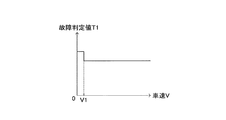
前記車両の速度である車速が遅い場合には、前記車速が速い場合に比べて前記故障判定値を大きくする車速応答故障判定値設定手段(S120)を備えたことにある。
A feature of one aspect of the present invention is that
When the vehicle speed, which is the vehicle speed, is slow, vehicle speed response failure determination value setting means (S120) for increasing the failure determination value compared to when the vehicle speed is high is provided.
残りの1系統の回転角センサが故障していない場合に、操舵トルクが故障判定値以上になると1系統の回転角センサが故障していると誤判定する可能性が高くなる。その一方、据え切り操舵時、極低速走行中の操舵時においては、操舵トルクが増加しやすいので、操舵トルクが故障判定値以上になる可能性が高くなる。そこで、本発明の一側面では、車速応答故障判定値設定手段が、車速が遅い場合には、車速が速い場合に比べて故障判定値を大きくする。従って、本発明の一側面によれば、残り1系統の回転角センサの故障検出精度を維持しつつ、故障検出に係る誤判定(故障していないものを故障していると判定する誤り)を低減することができる。 In the case where the remaining one system of rotation angle sensors has not failed, if the steering torque becomes greater than or equal to the failure determination value, there is a high possibility of erroneous determination that the one system of rotation angle sensors has failed. On the other hand, during stationary steering and during steering at extremely low speeds, the steering torque is likely to increase, so the possibility that the steering torque becomes equal to or greater than the failure determination value increases. Therefore, according to one aspect of the present invention, the vehicle speed response failure determination value setting means increases the failure determination value when the vehicle speed is low compared to when the vehicle speed is high. Therefore, according to one aspect of the present invention, while maintaining the failure detection accuracy of the remaining one rotation angle sensor, an erroneous determination related to failure detection (an error that determines that a non-failed one is failed) is performed. Can be reduced.
本発明の一側面の特徴は、
前記モータ制御手段が前記モータの出力制限をする出力制限モードにて動作している場合には、前記出力制限モードにて動作していない場合に比べて前記故障判定値を大きくする出力制限応答故障判定値設定手段(S120)を備えたことにある。
A feature of one aspect of the present invention is that
When the motor control unit is operating in the output limit mode that limits the output of the motor, the output limit response failure that increases the failure determination value compared to when not operating in the output limit mode The determination value setting means (S120) is provided.
一般に、電動パワーステアリング装置は、モータの過熱防止などのために、モータの出力を制限する機能を備えている。そうしたモータの出力を制限する出力制限モードにて動作している場合には、操舵アシストトルクが通常モード(出力制限モードにて動作していないモード)に比べて制限される。このため、ドライバーが操舵ハンドルに入力する力、つまり、トルク検出手段により検出される操舵トルクが増加しやすい。 In general, the electric power steering apparatus has a function of limiting the output of the motor in order to prevent overheating of the motor. When operating in such an output limiting mode that limits the output of the motor, the steering assist torque is limited compared to the normal mode (mode not operating in the output limiting mode). For this reason, the force input by the driver to the steering wheel, that is, the steering torque detected by the torque detection means tends to increase.
そこで、本発明の一側面では、出力制限応答故障判定値設定手段が、モータの出力制限をする出力制限モードにて動作している場合には、出力制限モードにて動作していない場合に比べて故障判定値を大きくする。従って、本発明の一側面によれば、残り1系統の回転角センサの故障検出精度を維持しつつ、故障検出に係る誤判定を低減することができる。 Therefore, in one aspect of the present invention, when the output limit response failure determination value setting unit is operating in the output limit mode that limits the output of the motor, compared to when not operating in the output limit mode. Increase the failure judgment value. Therefore, according to one aspect of the present invention, it is possible to reduce erroneous determination related to failure detection while maintaining failure detection accuracy of the remaining one system of rotation angle sensors.
本発明の一側面の特徴は、
前記操舵ハンドルが操舵限界位置から所定範囲内に位置する場合には、前記操舵ハンドルが前記操舵限界位置から所定範囲内に位置しない場合に比べて前記故障判定値を大きくする操舵位置応答故障判定値設定手段(S120)を備えたことにある。
A feature of one aspect of the present invention is that
When the steering handle is positioned within a predetermined range from the steering limit position, a steering position response failure determination value that increases the failure determination value compared to when the steering handle is not positioned within the predetermined range from the steering limit position The setting means (S120) is provided.
例えば、操舵ハンドルを大きく操舵操作して操舵位置が操舵限界位置に到達した場合には、操舵ハンドルをそれ以上回すことができなくなり、操舵トルクが急激に増加する可能性がある。 For example, when the steering wheel is largely steered and the steering position reaches the steering limit position, the steering wheel cannot be further rotated, and the steering torque may increase rapidly.
そこで、本発明の一側面では、操舵位置応答故障判定値設定手段が、操舵ハンドルが操舵限界位置から所定範囲内に位置する場合には、操舵ハンドルが操舵限界位置から所定範囲内に位置しない場合に比べて故障判定値を大きくする。「操舵ハンドルが操舵限界位置から所定範囲内に位置する」とは、操舵ハンドルが操舵限界位置近傍に位置することを意味している。従って、本発明の一側面によれば、残り1系統の回転角センサの故障検出精度を維持しつつ、故障検出に係る誤判定を低減することができる。 Therefore, according to one aspect of the present invention, the steering position response failure determination value setting unit is configured such that when the steering handle is located within a predetermined range from the steering limit position, the steering handle is not located within the predetermined range from the steering limit position. The failure judgment value is made larger than “The steering handle is positioned within a predetermined range from the steering limit position” means that the steering handle is positioned in the vicinity of the steering limit position. Therefore, according to one aspect of the present invention, it is possible to reduce erroneous determination related to failure detection while maintaining failure detection accuracy of the remaining one system of rotation angle sensors.
本発明の一側面の特徴は、
前記センサ故障判定手段は、前記操舵トルクが予め設定された故障判定値以上となる継続時間が設定時間以上となる挙動が検出された場合、前記モータ制御手段が前記モータを駆動制御するために用いる回転角に所定回転角を加算し、前記所定回転角の加算後に、前記回転角検出手段によって検出される回転角の変化が生じない場合に、前記残り1系統の回転角センサが故障したことを確定する(S30,S31)ように構成されたことにある。
A feature of one aspect of the present invention is that
The sensor failure determination unit is used by the motor control unit to drive and control the motor when a behavior in which a duration time during which the steering torque is equal to or greater than a predetermined failure determination value is detected is equal to or longer than a set time is detected. When a predetermined rotation angle is added to the rotation angle, and no change in the rotation angle detected by the rotation angle detection means occurs after the addition of the predetermined rotation angle, the remaining one rotation angle sensor has failed. This is because it is configured to confirm (S30, S31).
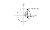
本発明の一側面では、操舵トルクが予め設定された故障判定値以上となる継続時間が設定時間以上となる挙動が検出された場合、すぐに、残り1系統の回転角センサが故障したことを確定するのではなく、モータ制御手段がモータを駆動制御するために用いる回転角に所定回転角を加算し、所定回転角の加算後に、回転角検出手段によって検出される回転角の変化が生じない場合に、残り1系統の回転角センサが故障したことを確定する。モータ回転角に所定回転角が加算されると、モータ制御手段は、その加算量に対応した量だけモータの電気角を変化させる。従って、モータの出力する操舵アシストトルクが変化し、操舵ハンドルが回転する。例えば、所定回転角度は、操舵トルクの働いている方向に加算されることが好ましいが、その反対方向であってもよい。 In one aspect of the present invention, when a behavior in which the duration for which the steering torque is equal to or greater than a preset failure determination value is detected for a set time or more is detected, the remaining one rotation angle sensor is immediately failed. Rather than confirming, the motor control means adds a predetermined rotation angle to the rotation angle used to drive and control the motor, and no change in the rotation angle detected by the rotation angle detection means occurs after the addition of the predetermined rotation angle. In this case, it is determined that the remaining one rotation angle sensor has failed. When the predetermined rotation angle is added to the motor rotation angle, the motor control means changes the electric angle of the motor by an amount corresponding to the addition amount. Accordingly, the steering assist torque output from the motor changes, and the steering handle rotates. For example, the predetermined rotation angle is preferably added in the direction in which the steering torque is applied, but may be in the opposite direction.
このとき、残り1系統の回転角センサが故障していなければ、回転角検出手段によって検出される検出される回転角は変化するはずである。このことを利用して、センサ故障判定手段は、所定回転角の加算後に、回転角検出手段によって検出される回転角の変化が生じない場合に、残り1系統の回転角センサが故障したことを確定する。従って、本発明の一側面によれば、残り1系統の回転角センサの故障検出精度を維持しつつ、故障検出に係る誤判定を低減することができる。 At this time, if the remaining one rotation angle sensor has not failed, the detected rotation angle detected by the rotation angle detecting means should change. By utilizing this fact, the sensor failure determination means determines that the remaining one rotation angle sensor has failed when the rotation angle detected by the rotation angle detection means does not change after the addition of the predetermined rotation angle. Determine. Therefore, according to one aspect of the present invention, it is possible to reduce erroneous determination related to failure detection while maintaining failure detection accuracy of the remaining one system of rotation angle sensors.
本発明の一側面の特徴は、
前記センサ故障判定手段は、前記所定回転角の加算後に、前記回転角検出手段によって検出される回転角の変化が生じなく、かつ、前記モータで発生する誘起電圧の大きさが前記モータの回転状態を判定する設定電圧より大きい場合に、前記残り1系統の回転角センサが故障したことを確定する(S30,S31,S32)ように構成されたことにある。
A feature of one aspect of the present invention is that
The sensor failure determination means does not cause a change in the rotation angle detected by the rotation angle detection means after the addition of the predetermined rotation angle, and the magnitude of the induced voltage generated in the motor is the rotation state of the motor. When the voltage is larger than the set voltage for determining, it is determined that the remaining one rotation angle sensor has failed (S30, S31, S32).
例えば、操舵ハンドルを回転できない状況(操舵ハンドルが操舵限界位置に到達している状況、操舵輪が轍にはまっている状況など)においては、モータの回転角に所定回転角を加算しても、操舵ハンドルは回転できないので、回転角検出手段によって検出される回転角が変化しない可能性がある。一方、モータで発生する誘起電圧が大きい場合には、モータが回転していると推定できる。 For example, in a situation where the steering wheel cannot be rotated (a situation where the steering wheel reaches the steering limit position, a situation where the steering wheel is trapped), even if a predetermined rotation angle is added to the rotation angle of the motor, Since the steering handle cannot rotate, there is a possibility that the rotation angle detected by the rotation angle detection means does not change. On the other hand, when the induced voltage generated in the motor is large, it can be estimated that the motor is rotating.
このことを利用して、センサ故障判定手段は、所定回転角の加算後に、回転角検出手段によって検出される回転角の変化が生じなく、かつ、モータで発生する誘起電圧の大きさがモータの回転状態を判定する設定電圧より大きい場合に、残り1系統の回転角センサが故障したことを確定する。従って、本発明の一側面によれば、残り1系統の回転角センサの故障検出精度を維持しつつ、故障検出に係る誤判定を更に低減することができる。 By utilizing this, the sensor failure determination means does not cause a change in the rotation angle detected by the rotation angle detection means after addition of the predetermined rotation angle, and the magnitude of the induced voltage generated in the motor is When it is larger than the set voltage for determining the rotation state, it is determined that the remaining one rotation angle sensor has failed. Therefore, according to one aspect of the present invention, it is possible to further reduce the erroneous determination related to the failure detection while maintaining the failure detection accuracy of the remaining one rotation angle sensor.
本発明の一側面の特徴は、
前記モータ制御値演算手段は、前記センサ故障判定手段によって1系統の回転角センサの故障が検出されている場合には、2系統ともに回転角センサの故障が検出されていない場合に比べて、前記操舵トルクに対する前記目標操舵アシストトルクの大きさを大きくするように構成されたことにある。
A feature of one aspect of the present invention is that
The motor control value calculation means is more effective when the failure of one rotation angle sensor is detected by the sensor failure determination means than when no rotation angle sensor failure is detected in both systems. It is configured to increase the magnitude of the target steering assist torque with respect to the steering torque.
残りの1系統の回転角センサが故障していない場合は、故障検出に係る誤判定を防止するために、できるだけ操舵トルクが故障判定値以上にならないようにする必要がある。そこで、モータ制御値演算手段は、1系統の回転角センサの故障が検出されている場合には、2系統ともに回転角センサの故障が検出されていない場合に比べて、操舵トルクに対する目標操舵アシストトルクの大きさを大きくする。これにより、1系統の回転角センサの故障が検出されている場合には、ハンドル操作が軽い設定になり(即ち、運転者がより小さい力で操舵ハンドルの操作が可能な状態となり)、操舵トルクが故障判定値以上になりにくいようにすることができる。従って、本発明の一側面によれば、残り1系統の回転角センサの故障検出精度を維持しつつ、故障検出に係る誤判定を低減することができる。尚、操舵トルクの全域において、操舵トルクに対する目標操舵アシストトルクの大きさを大きくする必要はなく、少なくとも操舵トルクの一部の範囲において、そのような関係が設定されていればよい。 When the remaining one system of rotation angle sensors has not failed, it is necessary to prevent the steering torque from exceeding the failure determination value as much as possible in order to prevent erroneous determination related to failure detection. Therefore, the motor control value calculation means, when a failure of the rotation angle sensor of one system is detected, compared with a case where a failure of the rotation angle sensor is not detected in both systems, the target steering assist for the steering torque. Increase the magnitude of the torque. As a result, when a failure of one rotation angle sensor is detected, the steering wheel operation is lightly set (that is, the driver can operate the steering wheel with a smaller force), and the steering torque is reduced. Can be made less likely to exceed the failure judgment value. Therefore, according to one aspect of the present invention, it is possible to reduce erroneous determination related to failure detection while maintaining failure detection accuracy of the remaining one system of rotation angle sensors. Note that it is not necessary to increase the magnitude of the target steering assist torque with respect to the steering torque in the entire range of the steering torque, and it is sufficient that such a relationship is set at least in a partial range of the steering torque.
本発明の一側面の特徴は、
前記2系統の回転角センサ(31,32)は、それぞれ、2つの磁気センサ(Ss1,Sc1,Ss2,Sc2)を備え、
前記2つの磁気センサは、それぞれ、電源回路から電圧が印加される直列に接続された2つの磁気抵抗効果素子(Ele1,Ele2)を備え、前記2つの磁気抵抗効果素子の接続点の電圧信号であって、前記モータの回転に伴って正弦波状に変化し、互いに位相がπ/2だけずれた振幅の等しい電圧信号を出力するように構成され、
前記特定の挙動は、前記操舵トルクが予め設定された周波数範囲で周期的に変化する挙動を含む(S108,S109)ことにある。
A feature of one aspect of the present invention is that
Each of the two rotation angle sensors (31, 32) includes two magnetic sensors (Ss1, Sc1, Ss2, Sc2),
Each of the two magnetic sensors includes two magnetoresistive elements (Ele1 and Ele2) connected in series to which a voltage is applied from a power supply circuit, and a voltage signal at a connection point of the two magnetoresistive elements. And is configured to output sinusoidal voltage signals with the rotation of the motor, and to output voltage signals having equal amplitudes whose phases are shifted from each other by π / 2,
The specific behavior includes a behavior in which the steering torque periodically changes in a preset frequency range (S108, S109).
本発明の一側面においては、2系統の回転角センサは、それぞれ、2つの磁気センサを備えている。この磁気センサは、それぞれ、電源回路から電圧が印加される直列に接続された2つの磁気抵抗効果素子を備え、2つの磁気抵抗効果素子の接続点の電圧信号であって、モータの回転に伴って正弦波状に変化し、互いに位相がπ/2だけずれた振幅の等しい電圧信号を出力する。これにより、一方の磁気センサの電圧信号から正弦波電圧信号が得られ、他方の電圧信号から余弦波電圧信号が得られる。従って、2つの信号の電圧値(直流成分の除いた電圧値)の逆正接を計算することにより、モータ回転角を求めることができる。 In one aspect of the present invention, each of the two systems of rotation angle sensors includes two magnetic sensors. Each of the magnetic sensors includes two magnetoresistive elements connected in series to which a voltage is applied from a power supply circuit, and is a voltage signal at a connection point of the two magnetoresistive elements, and is accompanied by rotation of the motor. Thus, voltage signals having the same amplitude and having phases shifted from each other by π / 2 are output. Thereby, a sine wave voltage signal is obtained from the voltage signal of one magnetic sensor, and a cosine wave voltage signal is obtained from the other voltage signal. Therefore, the motor rotation angle can be obtained by calculating the arc tangent of the voltage values of the two signals (voltage values excluding the DC component).
回転角センサにおいては、正弦波電圧成分の電圧値(正弦波電圧信号から直流成分の除いた電圧値)の二乗と、余弦波電圧成分の電圧値(余弦波電圧信号から直流成分の除いた電圧値)の二乗との和に応じた値(例えば、上記和の平方根)を演算し、その演算値が予め定まった所定値とならない場合には、故障していると判断することができる。 In the rotation angle sensor, the square of the voltage value of the sine wave voltage component (voltage value obtained by removing the DC component from the sine wave voltage signal) and the voltage value of the cosine wave voltage component (voltage obtained by removing the DC component from the cosine wave voltage signal) If a value (for example, the square root of the sum) is calculated according to the sum of the square of the value and the calculated value does not become a predetermined value, it can be determined that a failure has occurred.
しかし、回転角センサ(2つの磁気センサ)の電源電圧が正常電圧よりも低い中間電圧に固着するという故障が発生して中間点の電位が変化した場合には、磁気センサの出力する電圧信号の原点がずれる。1系統の回転角センサが故障している状況においては、上記の演算値では、モータ回転角によっては、故障を検出できない範囲がある。つまり、正弦波電圧成分の電圧値の二乗と、余弦波電圧成分の電圧値の二乗との和に応じた値が、特定のモータ回転角の範囲において正常となる。このため、速い操舵操作が行われたときには、回転角センサの故障検出に至らないおそれがある。 However, when a failure occurs in which the power supply voltage of the rotation angle sensor (two magnetic sensors) is fixed to an intermediate voltage lower than the normal voltage and the potential at the intermediate point changes, the voltage signal output from the magnetic sensor The origin is shifted. In a situation where one system of rotation angle sensors is out of order, the above calculation value has a range in which the failure cannot be detected depending on the motor rotation angle. That is, a value corresponding to the sum of the square of the voltage value of the sine wave voltage component and the square of the voltage value of the cosine wave voltage component becomes normal in a specific motor rotation angle range. For this reason, when a fast steering operation is performed, there is a possibility that failure of the rotation angle sensor will not be detected.
一方、こうした電源故障が発生した場合には、操舵ハンドルが操作されているあいだ、操舵トルクが周期的に変動する。こうした故障時の特徴を捉えて、本発明の一側面においては、操舵トルクが予め設定された周波数範囲で周期的に変化する場合に、残り1系統の回転角センサが故障したと判定する。この予め設定された周波数範囲は、残り1系統の回転角センサの電源電圧が中間電圧に固着した場合に想定される操舵トルクの振動周波数の範囲に設定される。従って、上記の電源故障が発生した場合には、適正に故障判定を行うことができる。 On the other hand, when such a power failure occurs, the steering torque fluctuates periodically while the steering wheel is being operated. In view of such failure characteristics, in one aspect of the present invention, when the steering torque periodically changes in a preset frequency range, it is determined that the remaining one rotation angle sensor has failed. This preset frequency range is set to the range of the vibration frequency of the steering torque assumed when the power supply voltage of the remaining one rotation angle sensor is fixed to the intermediate voltage. Therefore, when the above power failure occurs, the failure can be properly determined.
上記説明においては、発明の理解を助けるために、実施形態に対応する発明の構成に対して、実施形態で用いた符号を括弧書きで添えているが、発明の各構成要件は、前記符号によって規定される実施形態に限定されるものではない。 In the above description, in order to help the understanding of the invention, the reference numerals used in the embodiments are attached to the configuration of the invention corresponding to the embodiments in parentheses, but each constituent element of the invention is represented by the reference numerals. It is not limited to the embodiments specified.
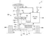
以下、本発明の実施形態に係る車両の電動パワーステアリング装置について図面を用いて説明する。図1は、同実施形態に係る車両の電動パワーステアリング装置1の概略構成を表している。
Hereinafter, an electric power steering device for a vehicle according to an embodiment of the present invention will be described with reference to the drawings. FIG. 1 shows a schematic configuration of an electric
この電動パワーステアリング装置1は、操舵ハンドル11の操舵操作により転舵輪を転舵するステアリング機構10と、ステアリング機構10に組み付けられ操舵アシストトルクを発生するモータ20と、操舵ハンドル11の操作状態に応じてモータ20の作動を制御する電子制御ユニット100とを主要部として備えている。以下、電子制御ユニット100をアシストECU100と呼ぶ。
The electric
ステアリング機構10は、操舵ハンドル11の回動操作に連動したステアリングシャフト12の軸線周りの回転をラックアンドピニオン機構13によりラックバー14の左右方向のストローク運動に変換して、このラックバー14のストローク運動により左前輪Wflと右前輪Wfrとを転舵するようになっている。ステアリングシャフト12は、操舵ハンドル11を上端に連結したメインシャフト12aと、ラックアンドピニオン機構13と連結されるピニオンシャフト12cと、メインシャフト12aとピニオンシャフト12cとをユニバーサルジョイント12d,12eを介して連結するインターミディエイトシャフト12bとから構成される。
The
ラックバー14は、ギヤ部14aがラックハウジング15内に収納され、その左右両端がラックハウジング15から露出してタイロッド16と連結される。左右のタイロッド16の他端は、左右前輪Wfl,Wfrに設けられたナックル(図示略)に接続される。以下、左前輪Wflと右前輪Wfrとを単に転舵輪Wと呼ぶ。
The
ステアリングシャフト12(メインシャフト12a)には、トルクセンサ21と操舵角センサ22が設けられている。トルクセンサ21は、ステアリングシャフト12(メインシャフト12a)に介装されているトーションバー12tの捩れ角度を検出し、この捩れ角に基づいて、操舵ハンドル11からステアリングシャフト12に入力された操舵トルクTrを検出する。操舵角センサ22は、操舵ハンドル11の回転角度を操舵角θhとして検出する。
A
操舵トルクTrは、正負の値により操舵ハンドル11の操作方向が識別される。例えば、操舵ハンドル11の左方向への操舵時における操舵トルクTrは正の値で、操舵ハンドル11の右方向への操舵時における操舵トルクTrは負の値で示される。また、操舵角θhは、正負の値により中立位置に対する操舵方向が識別される。例えば、左方向の操舵角θは正の値で、右方向の操舵角θは負の値で示される。また、操舵トルクTrの大きさ、操舵角θの大きさは、その絶対値で示される。
As for the steering torque Tr, the operation direction of the
ステアリングシャフト12(メインシャフト12a)には減速機25を介してモータ20が組み付けられている。モータ20は、例えば、三相ブラシレスモータが使用される。モータ20は、ロータの回転により減速機25を介してステアリングシャフト12をその中心軸周りに回転駆動して、操舵ハンドル11の回動操作に対してアシストトルクを付与する。
A
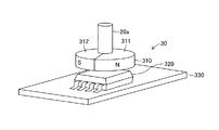
モータ20には、ロータ20aの回転角を検出する回転角センサユニット30が設けられる。回転角センサユニット30は、図2に示すように、モータ20のロータ20aの一方端に固定して取り付けられるマグネット部310と、マグネット部310に向かい合うように設けられるセンサ部320とを備えている。センサ部320は、モータ20のケーシング(図示略)との相対位置が変わらないように固定された基板330に設けられる。マグネット部310は、モータ20のロータ20aと同軸状に設けられる円盤形状の磁性部材であって、その半分の領域311(半月状の領域)がN極に着磁され、残り半分の領域312(半月状の領域)がS極に着磁されている。
The
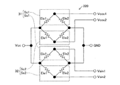
センサ部320は、マグネット部310の円盤状の平面に対して、モータ20のロータ20aの軸方向に所定のギャップをあけて設けられる。センサ部320には、図3に示すように、第1回転角センサ31と第2回転角センサ32とを備えている。第1回転角センサ31は、2つの磁気センサSs1,Sc1を備え、第2回転角センサ32は、2つの磁気センサSs2,Sc2を備える。
The
モータ20の回転角を検出するためには、第1回転角センサ31と第2回転角センサ32の何れか一方だけを備えていればよいが、一方が故障した場合のバックアップとして2つの回転角センサ31,32が設けられている。そのため、回転角センサユニット30は、2系統の回転角センサ31,32を備えていることになる。以下、2系統の回転角センサ31,32と呼ぶ場合は、第1回転角センサ31と第2回転角センサ32との両方を表し、1系統の回転角センサ31(32)と呼ぶ場合は、第1回転角センサ31と第2回転角センサ32との何れか一方を表す。
In order to detect the rotation angle of the
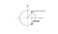
各磁気センサSs1,Sc1,Ss2,Sc2は、特定方向の磁界の強度に応じて電気抵抗値が変化する特性を有する2つの薄膜強磁性金属エレメント(磁気抵抗効果素子)Ele1,Ele2を備えている。各磁気センサSs1,Sc1,Ss2,Sc2においては、2つのエレメントEle1,Ele2が直列に接続され、その両端に電圧Vccが印加され(直列接続された一方のエレメントEle1の端と他方のエレメントEle2の端との間に電圧Vccが印加され)、2つのエレメントEle1,Ele2の接続点(中間点)における電位を表す電圧信号Vsin1,Vcos1,Vsin2,Vcos2を出力する。磁気抵抗効果素子を用いた磁気センサは、一般に、MRセンサと呼ばれているため、以下、磁気センサSs1,Sc1,Ss2,Sc2をMRセンサSs1,Sc1,Ss2,Sc2と呼ぶ。 Each of the magnetic sensors Ss1, Sc1, Ss2, and Sc2 includes two thin film ferromagnetic metal elements (magnetoresistance effect elements) Ele1 and Ele2 having a characteristic that the electric resistance value changes according to the strength of the magnetic field in a specific direction. . In each magnetic sensor Ss1, Sc1, Ss2, Sc2, two elements Ele1, Ele2 are connected in series, and a voltage Vcc is applied to both ends thereof (the end of one element Ele1 connected in series and the other element Ele2). A voltage Vcc is applied between the two terminals E1 and Ele2, and voltage signals Vsin1, Vcos1, Vsin2, and Vcos2 representing the potential at the connection point (intermediate point) of the two elements Ele1 and Ele2 are output. Since a magnetic sensor using a magnetoresistive element is generally called an MR sensor, the magnetic sensors Ss1, Sc1, Ss2, and Sc2 are hereinafter referred to as MR sensors Ss1, Sc1, Ss2, and Sc2.
このセンサ部320においては、2つの回転角センサ31,32に対して共通の電源回路を使用するように構成されており、各MRセンサSs1,Sc1,Ss2,Sc2の一方端が共通の電源端子に接続され、他方端が共通のグランド端子に接続されている。
The
2つのエレメントEle1,Ele2は、その配設される向きが互いに異なるように設けられている。つまり、エレメントEle1,Ele2に作用する磁界の方向に対して電気抵抗値の変化する特性が異なるように設けられている。このため、マグネット部310が回転して各エレメントEle1,Ele2に作用する磁界の向きが回転すると、それに同期してMRセンサSの出力信号の電圧が変動する。この電圧変動分は、モータ20の回転角度に応じた正弦波状に変化する。
The two elements Ele1 and Ele2 are provided so that their orientations are different from each other. That is, the characteristic in which the electric resistance value changes with respect to the direction of the magnetic field acting on the elements Ele1 and Ele2 is provided. For this reason, when the
センサ部320における4つのMRセンサSs1,Sc1,Ss2,Sc2は、モータ20の回転に伴って正弦波状に電圧が変動する周期信号を出力するが、この出力信号の電圧波形の位相が、π/2ずつずれるように配置して設けられる。
The four MR sensors Ss1, Sc1, Ss2, Sc2 in the
MRセンサSs1の出力電圧をVsin1、MRセンサSc1の出力電圧をVcos1、MRセンサSs2の出力電圧をVsin2、MRセンサSc2の出力電圧をVcos2とすると、出力電圧Vsin1,Vcos1,Vsin2,Vcos2は次式(1)〜(4)のように表される。
Vsin1=Vcc/2+Vt・sinθ ・・・(1)
Vcos1=Vcc/2+Vt・cosθ ・・・(2)
Vsin2=Vcc/2−Vt・sinθ ・・・(3)
Vcos2=Vcc/2−Vt・cosθ ・・・(4)
θは、予め設定したマグネット部310とセンサ部320との相対回転基準位置からマグネット部310が回転した角度を表す。Vtは、一定の電圧振幅を表す。
When the output voltage of the MR sensor Ss1 is Vsin1, the output voltage of the MR sensor Sc1 is Vcos1, the output voltage of the MR sensor Ss2 is Vsin2, and the output voltage of the MR sensor Sc2 is Vcos2, the output voltages Vsin1, Vcos1, Vsin2, and Vcos2 are It is expressed as (1) to (4).
Vsin1 = Vcc / 2 + Vt · sinθ (1)
Vcos1 = Vcc / 2 + Vt · cos θ (2)
Vsin2 = Vcc / 2−Vt · sin θ (3)
Vcos2 = Vcc / 2−Vt · cos θ (4)
θ represents an angle of rotation of the
MRセンサSs1,Sc1,Ss2,Sc2の出力電圧Vsin1,Vcos1,Vsin2,Vcos2を、そこに含まれる直流分(Vcc/2)だけオフセットすることにより、互いに位相がπ/2だけずれた正弦波状(=余弦波状)の電圧信号が得られる。モータ回転角の計算にあたっては、出力電圧Vsin1,Vcos1,Vsin2,Vcos2から、直流分(Vcc/2=一定)をオフセットした電圧値、つまり、正弦波電圧信号の振幅の中心(Vcc/2)をゼロV(原点)とした電圧値が用いられる。従って、以下、モータ回転角の計算に用いられる出力電圧Vsin1,Vcos1,Vsin2,Vcos2については、次式(5)〜(8)のように置き換えればよい。
Vsin1=Vt・sinθ ・・・(5)
Vcos1=Vt・cosθ ・・・(6)
Vsin2=−Vt・sinθ ・・・(7)
Vcos2=−Vt・cosθ ・・・(8)
尚、MRセンサSs1,Sc1,Ss2,Sc2が、その出力信号がモータ20の1回転に対してN周期(N:自然数)で変動するように構成されているタイプである場合には、実際のモータ20のロータ20aの回転角は、モータ回転角θの1/Nとして計算すればよい。以下、MRセンサSs1,Sc1,Ss2,Sc2の出力信号におけるθをモータ回転角として説明する。
By offsetting the output voltages Vsin1, Vcos1, Vsin2, and Vcos2 of the MR sensors Ss1, Sc1, Ss2, and Sc2 by a direct current component (Vcc / 2) included therein, the phases are shifted from each other by π / 2 ( = Cosine waveform) is obtained. When calculating the motor rotation angle, the voltage value obtained by offsetting the DC component (Vcc / 2 = constant) from the output voltages Vsin1, Vcos1, Vsin2, and Vcos2, that is, the center of the amplitude of the sinusoidal voltage signal (Vcc / 2) is used. A voltage value with zero V (origin) is used. Therefore, hereinafter, the output voltages Vsin1, Vcos1, Vsin2, and Vcos2 used for calculating the motor rotation angle may be replaced as in the following equations (5) to (8).
Vsin1 = Vt · sinθ (5)
Vcos1 = Vt · cosθ (6)
Vsin2 = −Vt · sinθ (7)
Vcos2 = −Vt · cosθ (8)
When the MR sensors Ss1, Sc1, Ss2, and Sc2 are of a type configured so that the output signal fluctuates in N cycles (N: natural number) with respect to one rotation of the
このように構成されたセンサ部320においては、第1回転角センサ31から、互いにπ/2位相のずれた出力電圧Vsin1,Vcos1をアシストECU100に出力し、第2回転角センサ32から、互いにπ/2位相のずれた出力電圧Vsin2,Vcos2をアシストECU100に出力する。以下、第1回転角センサ31の出力する電圧信号を検出信号Vsin1,Vcos1と呼び、第2回転角センサ32の出力する電圧信号を検出信号Vsin2,Vcos2と呼ぶ。アシストECU100は、この検出信号Vsin1,Vcos1,Vsin2,Vcos2を使って、モータ20の回転角θを計算し、この回転角θからモータ20の位相を制御するために必要な電気角を算出する。
In the
次に、アシストECU100について説明する。アシストECU100は、上述したトルクセンサ21,操舵角センサ22、回転角センサユニット30に加えて、車速センサ23を接続している。車速センサ23は、車速Vを表す検出信号をアシストECU100に出力する。
Next, the assist
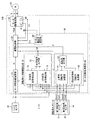
アシストECU100は、図4に示すように、モータ20の目標制御量を計算し、計算された目標制御量に応じたスイッチ駆動信号を出力するアシスト演算部50と、アシスト演算部50から出力されたスイッチ駆動信号によってモータ20を駆動するモータ駆動回路40とを備えている。モータ駆動回路40は、例えば、インバータ回路で構成され、アシスト演算部50から出力されたスイッチ駆動信号(PWM制御信号)を入力して、内部のスイッチング素子のデューティ比を制御することによりモータ20への通電量を調整する。モータ駆動回路40には、モータ20の3相に流れるモータ電流Imを検出する電流センサ41,および、モータ20の3相端子の端子電圧Vmを検出する電圧センサ42が設けられる。
As shown in FIG. 4, the assist
アシスト演算部50は、CPU,ROM,RAM等からなるマイクロコンピュータと、各種の入出力インタフェースと、モータ駆動回路40にスイッチ駆動信号を供給するスイッチ駆動回路等を備えている。
The
アシスト演算部50は、その機能に着目すると、モータ20の制御量である指令電流値を計算するモータ制御量演算部51と、指令電流値に対応した3相の電流がモータ20に流れるようにモータ駆動回路40の作動を制御する通電制御部52と、回転角センサユニット30から出力された検出信号Vsin1,Vcos1、Vsin2,Vcos2に基づいてモータ回転角θを計算するモータ回転角演算部60と、回転角センサユニット30の故障を検出する回転角センサ故障検出部70とを備えている。
Focusing on the function of the
モータ制御量演算部51は、トルクセンサ21により検出される操舵トルクTrを入力して、図5(a)に示す正常時アシストマップを参照して目標アシストトルクTa*を計算する。正常時アシストマップは、操舵トルクTrと目標アシストトルクTa*との関係を設定した関係付けデータであり、操舵トルクTrの大きさ(絶対値)が大きくなるほど大きくなる目標アシストトルクTa*を設定する特性を有する。尚、図5は、左方向の操舵アシスト特性を表しているが、右方向の操舵アシスト特性についても、トルクの発生方向が異なるだけで、大きさは、左方向の操舵アシスト特性と同じである。また、目標アシストトルクTa*の計算にあたっては、例えば、操舵トルクTrと車速Vとを組み合わせて、操舵トルクTrの大きさ(絶対値)が大きくなるほど大きくなり、かつ、車速Vが大きくなるほど小さくなる目標アシストトルクTa*を設定するなどしてもよい。
The motor control
モータ制御量演算部51は、目標アシストトルクTa*を入力し、目標アシストトルクTa*をモータ20のトルク定数で除算することにより、目標アシストトルクTa*を発生させるために必要な目標電流であるアシスト指令電流I*を計算する。モータ制御量演算部51は、算出したアシスト指令電流I*を通電制御部52に供給する。
The motor control
通電制御部52は、電流センサ41により検出されるモータ電流Im(実電流Imと呼ぶ)を読み込み、アシスト指令電流I*と実電流Imとの偏差を計算し、この偏差を使った比例積分制御により実電流Imがアシスト指令電流I*に追従するように目標電圧V*を計算する。そして、目標電圧V*に対応したPWM制御信号(スイッチ駆動信号)をモータ駆動回路(インバータ)40のスイッチング素子に出力する。これにより、モータ20が駆動され、目標アシストトルクTa*に追従した操舵アシストトルクがステアリング機構10に付与される。
The
この場合、通電制御部52は、モータ回転角演算部60から供給されたモータ回転角θを入力し、このモータ回転角θを電気角に変換して、その電気角に基づいてアシスト指令電流I*の位相角を制御する。例えば、通電制御部52は、モータ回転角θから換算される電気角に基づいて、モータ20の永久磁石の磁界が貫く方向となるd軸と、d軸に直交する方向(d軸からπ/2だけ電気角を進めた方向)となるq軸とを定めたd−q座標を用いた電流ベクトル制御によりモータ20を駆動制御する。
In this case, the
また、通電制御部52は、回転角センサ故障検出部70から回転角センサユニット30の故障の検出状況を表す故障検出信号Failを入力する。この故障検出信号Failは、回転角センサユニット30における系統毎の故障の有無、つまり、第1回転角センサ31と第2回転角センサ32との故障の有無について、故障している系統を特定して表す信号である。通電制御部52は、故障検出信号Failが、回転角センサユニット30の故障が検出されていない、あるいは、1系統の回転角センサのみ(第1回転角センサ31あるいは第2回転角センサ32)の故障が検出されていることを表している場合には、操舵アシスト制御を継続する。つまり、操舵トルクTrに応じた操舵アシストを実施する。一方、故障検出信号Failが、2系統の回転角センサ(第1回転角センサ31と第2回転角センサ32との両方)の故障が検出されていることを表している場合には、操舵アシストを停止する。
In addition, the
モータ回転角演算部60は、第1回転角センサ31、第2回転角センサ32の出力する検出信号(出力電圧Vsin1,Vcos1,Vsin2,Vcos2)を入力して、モータ回転角θを計算する。モータ回転角演算部60は、正常時回転角演算部61と、1系統故障時回転角演算部62と、回転角出力部63とを備えている。
The motor rotation angle calculation unit 60 inputs detection signals (output voltages Vsin1, Vcos1, Vsin2, Vcos2) output from the first
モータ回転角演算部60においては、回転角センサ故障検出部70から出力される故障検出信号Failを入力し、故障検出信号Failが、2系統の回転角センサ31,32がともに正常(故障が検出されていない状態)であることを表す場合には、正常時回転角演算部61がモータ回転角θを計算する。また、故障検出信号Failが、1系統の回転角センサのみ(第1回転角センサ31あるいは第2回転角センサ32)の故障が検出されていることを表している場合には、1系統故障時回転角演算部62が、故障が検出されていない方の回転角センサ31(32)を使って、モータ回転角θを計算する。
In the motor rotation angle calculation unit 60, the failure detection signal Fail output from the rotation angle sensor failure detection unit 70 is input, and the failure detection signal Fail indicates that both of the two
正常時回転角演算部61は、第1回転角センサ31、第2回転角センサ32のどちらを使ってもモータ回転角θを計算することができる。例えば、第1回転角センサ31の出力電圧Vsin1,Vcos1を使って、モータ回転角θを次式のように計算することができる。
θ=tan-1(sinθ/cosθ)=tan-1(Vsin1/Vcos1) ・・・(9)
同様に、第2回転角センサ32の出力電圧Vsin2,Vcos2を使って、モータ回転角を次式のように計算することができる。
θ=tan-1(sinθ/cosθ)=tan-1(Vsin2/Vcos2) ・・・(10)
The normal
θ = tan −1 (sin θ / cos θ) = tan −1 (Vsin1 / Vcos1) (9)
Similarly, using the output voltages Vsin2 and Vcos2 of the second
θ = tan −1 (sin θ / cos θ) = tan −1 (
モータ回転角θの計算にあたっては、解が2つ求められるが、sinθとcosθとが正の値である場合にはθが第1象限(0°〜90°)になる角度を選択し、sinθが正の値でcosθが負の値である場合にはθが第2象限(90°〜180°)になる角度を選択し、sinθが負の値でcosθが負の値である場合にはθが第3象限(180°〜270°)になる角度を選択し、sinθが負の値でcosθが正の値である場合にはθが第4象限(270°〜360°)になる角度を選択する。以下、逆正接の計算に当たっては、これに準じる。 In calculating the motor rotation angle θ, two solutions are obtained. If sin θ and cos θ are positive values, an angle at which θ becomes the first quadrant (0 ° to 90 °) is selected, and sin θ Is a positive value and cos θ is a negative value, the angle at which θ becomes the second quadrant (90 ° to 180 °) is selected, and when sin θ is a negative value and cos θ is a negative value, The angle at which θ becomes the third quadrant (180 ° to 270 °) is selected, and when sin θ is a negative value and cos θ is a positive value, the angle at which θ becomes the fourth quadrant (270 ° to 360 °) Select. Hereinafter, the calculation of arctangent is based on this.
また、第1回転角センサ31、第2回転角センサ32の両方が正常である場合であれば、モータ回転角θの計算は、2つの回転角センサ31,32におけるそれぞれ一方の出力信号(位相が互いにπ/2ずれている出力信号)を使って計算することができる。例えば、MRセンサSs1の出力電圧Vsin1とMRセンサSc2の出力電圧Vcos2とを用いれば、次式(11)によりモータ回転角θを計算することができる。
θ=tan-1(sinθ/cosθ)=tan-1(Vsin1/−Vcos2)・・・(11)
また、MRセンサSc1の出力電圧Vcos1とMRセンサSs2の出力電圧Vsin2とを用いた場合には、次式(12)によりモータ回転角θを計算することができる。
θ=tan-1(sinθ/cosθ)=tan-1(−Vsin2/Vcos1)・・・(12)
尚、このように式(11)あるいは式(12)を用いてモータ回転角を計算する場合には、MRセンサSs1とMRセンサSc2とにより第1回転角センサ31(あるいは第2回転角センサ32)が構成され、MRセンサSs2とMRセンサSc1とにより第2回転角センサ32(あるいは第1回転角センサ31)が構成されていると考えればよい。
Further, if both the first
θ = tan −1 (sin θ / cos θ) = tan −1 (Vsin1 / −Vcos2) (11)
When the output voltage Vcos1 of the MR sensor Sc1 and the output voltage Vsin2 of the MR sensor Ss2 are used, the motor rotation angle θ can be calculated by the following equation (12).
θ = tan −1 (sin θ / cos θ) = tan −1 (−Vsin2 / Vcos1) (12)
When the motor rotation angle is calculated using Equation (11) or Equation (12) in this way, the first rotation angle sensor 31 (or the second rotation angle sensor 32) is obtained by the MR sensor Ss1 and the MR sensor Sc2. It can be considered that the second rotation angle sensor 32 (or the first rotation angle sensor 31) is configured by the MR sensor Ss2 and the MR sensor Sc1.
また、第1回転角センサ31、第2回転角センサ32の出力する出力電圧Vsin1,Vcos1、Vsin2,Vcos2の全てを使ってモータ回転角θを計算することもできる。例えば、MRセンサSs1の出力電圧Vsin1とMRセンサSs2の出力電圧Vsin2との差(Vsin1−Vsin2)を表す電圧差Vs1-s2、および、MRセンサSc1の出力電圧Vcos1とMRセンサSc2の出力電圧Vcos2との差(Vcos1−Vcos2)を表す電圧差Vc1-c2は、次式(13),(14)のように表される。
Vs1-s2=Vt・sinθ−(−Vt・sinθ)=2Vt・sinθ・・・(13)
Vc1-c2=Vt・cosθ−(−Vt・cosθ)=2Vt・cosθ・・・(14)
従って、モータ回転角θは、次式(15)にて計算することもできる。
θ=tan-1(sinθ/cosθ)=tan-1(Vs1-s2/Vc1-c2)・・・(15)
Further, the motor rotation angle θ can be calculated using all of the output voltages Vsin1, Vcos1, Vsin2, and Vcos2 output from the first
Vs1−s2 = Vt · sin θ − (− Vt · sin θ) = 2 Vt · sin θ (13)
Vc1-c2 = Vt.cos .theta .- (-Vt.cos .theta.) = 2 Vt.cos .theta. (14)
Therefore, the motor rotation angle θ can be calculated by the following equation (15).
θ = tan −1 (sin θ / cos θ) = tan −1 (Vs1-s2 / Vc1-c2) (15)
正常時回転角演算部61は、このような計算式(9),(10),(11),(12)の1つを使って算出されたモータ回転角θ、あるいは、その計算式の複数を使って算出されたモータ回転角の平均値、あるいは、計算式(15)を使って算出されたモータ回転角を、計算結果として出力する。また、2系統の回転角センサ31,32のsin信号(Vsin1,Vsin2)同士、cos信号同士(Vcos1,Vcos2)の平均値を計算してから、その平均値を使ってモータ回転角θを計算するようにしてもよい。
The normal rotation
1系統故障時回転角演算部62は、故障が検出されていない系統の回転角センサ(第1回転角センサ31、あるいは、第2回転角センサ32)の出力する出力電圧に基づいて、計算式(9),(10),(11),(12)の何れかを使ってモータ回転角θを計算する。例えば、第1回転角センサ31のMRセンサSc1の故障が検出されている場合には、MRセンサSc1およびMRセンサSs1の検出信号Vsin1,Vcos1を用いずに、第2回転角センサ32の検出信号Vsin2,Vcos2を用いてモータ回転角θを計算する。
The one-system failure rotation
回転角出力部63は、正常時回転角演算部61あるいは1系統故障時回転角演算部62によって計算されたモータ回転角θを通電制御部52に出力する。
The rotation
回転角センサ故障検出部70は、1系統目故障検出部71と2系統目故障検出部72と故障信号出力部73とを備えている。1系統目故障検出部71は、2系統の回転角センサ(第1回転角センサ31と第2回転角センサ32)の両方に故障が検出されていない状況において作動し、2系統の回転角センサ31、32のうちの1つの系統の回転角センサ31(32)に故障が発生したか否かについて、故障が発生した系統の回転角センサ31(32)を特定して判定する。
The rotation angle sensor failure detection unit 70 includes a first system
一方、2系統目故障検出部72は、1系統目故障検出部71によって何れか1系統の回転角センサ31(32)の故障が検出されている状況において作動し、残り1系統の回転角センサ32(31)(故障が検出されていない回転角センサ)に故障が発生したか否かについて判定する。
On the other hand, the second-system
故障信号出力部73は、回転角センサユニット30の故障状況を表す故障検出信号Failを通電制御部52とモータ回転角演算部60とに出力する。故障検出信号Failは、例えば、2系統の回転角センサ31,32がともに正常(故障が検出されていない状態)である場合には「0」にて表され、第1回転角センサ31の故障のみが検出されている場合には「1」にて表され、第2回転角センサ32の故障のみが検出されている場合には「2」にて表され、第1回転角センサ31と第2回転角センサ32との両方の故障が検出されている場合には「3」にて表される。
The failure
1系統目故障検出部71は、第1回転角センサ31の出力信号と、第2回転角センサ32の出力信号とを用いて、両者の乖離の有無に基づいて、2系統の回転角センサ31(32)のうちの一方に故障が発生したか否かについて判定する。例えば、1系統目故障検出部71は、第1回転角センサ31の出力電圧Vsin1,Vcos1から計算されるモータ回転角(第1演算モータ回転角θ1と呼ぶ)と、第2回転角センサ32の出力電圧Vsin2,Vcos2から計算されるモータ回転角(第2演算モータ回転角θ2と呼ぶ)との偏差|θ1−θ2|を計算し、この偏差|θ1−θ2|が故障判定基準値よりも大きい場合には、2系統の回転角センサ31、32のうちの1つの系統の回転角センサ31(32)に故障が発生したと判定する。
The first system
1系統目故障検出部71の行う故障判定については、演算された第1演算モータ回転角θ1と第2演算モータ回転角θ2との比較に限るものではない。例えば、上記手法に代えて、あるいは、加えて、第1回転角センサ31の出力電圧Vsin1と第2回転角センサ32の出力電圧Vsin2との絶対値の比較(正常であれば一致)、符号の比較(正常であれば正負逆)等を行って故障判定を行ってもよい。同様に、第1回転角センサ31の出力電圧Vcos1と第2回転角センサ32の出力電圧Vcos2との絶対値の比較(正常であれば一致)、符号の比較(正常であれば正負逆)等を行って故障判定を行ってもよい。このように、1系統目故障検出部71においては、2系統の回転角センサ31,32の4つの出力信号を故障判定に利用できるため、故障判定を正確、かつ、迅速に行うことができる。
The failure determination performed by the first system
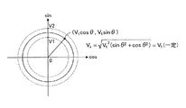
1系統目故障検出部71は、上記比較演算と並行して、第1回転角センサ31の出力電圧Vsin1,Vcos1の二乗値の和の平方根を表す二乗平均和√(Vsin12+Vcos12)、および、第2回転角センサ32の出力電圧Vsin2,Vcos2の二乗値の和の平方根を表す二乗平均和√(Vsin22+Vcos22)を計算している。故障の発生していない回転角センサ31(32)であれば、この計算結果は、√(Vt2(sinθ2+cosθ2))=Vtとなり、予め設定された一定値となる。
First system
第1演算モータ回転角θ1と第2演算モータ回転角θ2とが乖離している場合には、一方の回転角センサ31(32)の出力電圧の二乗平均和が異常値をとる。従って、1系統目故障検出部71は、計算した出力電圧の二乗平均和が許容範囲から外れている系統の回転角センサ31(32)を、故障の発生している回転角センサ31(32)として特定することができる。例えば、図6に示すように、二乗平均和の値をVxとすれば、二乗平均和Vxが許容範囲の下限値であるV1(=Vt−α)以上であって、許容範囲の上限値であるV2(=Vt+α)以下である場合(V1≦Vx≦V2)には、正常と判定し、それ以外の場合には、故障と判定すればよい。尚、平方根の計算は省略して、二乗和の計算により得られるVt2の大きさにより故障判定しても実質同じである。
When the first calculation motor rotation angle θ1 and the second calculation motor rotation angle θ2 are deviated, the mean square sum of the output voltages of one rotation angle sensor 31 (32) takes an abnormal value. Accordingly, the first system
2系統目故障検出部72は、1系統目故障検出部71によって故障が検出された系統とは異なる系統の回転角センサ31(32)の故障を検出する機能部である。上述したように、2系統の回転角センサ31,32がともに正常であれば、2系統の回転角センサ31,32の4つの出力信号を使って(比較して)、一方の回転角センサ31(32)に故障が発生したことを確実に判定できる。しかし、一方の回転角センサ31(32)の故障が検出された後においては、適正な比較対象が無くなるため、残り1つの回転角センサ31(32)に故障が発生したことを精度良く判定することは難しい。以下、その理由から説明する。
The second system
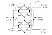
例えば、特許文献1に提案された回転角センサは、図7に示すように、2系統の回転角センサ31,32に対して、それぞれ独立した電源回路からMRセンサSs1,Sc1,Ss2,Sc2に電圧が印加されるように構成されている。この構成であれば、1系統の回転角センサ31(32)の故障が検出されている状況であっても、残りの1系統の回転角センサ32(31)において、2つのMRセンサSs2,Sc2(Ss1,Sc1)の出力電圧Vsin2,Vcos2(Vsin1,Vcos1)を比較すれば、故障を検出できる場合が多い。
For example, in the rotation angle sensor proposed in
しかし、本実施形態のように、電源端子、グランド端子を2つの回転角センサ31,32で共用している構成も一般的に採用されている。このように、2系統の回転角センサ31,32に対して電源回路を共用して備えた構成の場合、例えば、電源端子の電圧Vccが異常値(適正電圧よりも低い中間電圧値)に固着されてしまった場合(例えば、本来5Vであるはずの電源電圧Vccが3Vになっている等)など、残りの1系統の回転角センサ32(31)の有する2つのMRセンサSs2,Sc2(Ss1,Sc1)の出力信号が同時に影響を受けるような故障モードが発生する。この場合には、残り1つの回転角センサ32(31)において、2つのMRセンサSs2,Sc2(Ss1,Sc1)の出力電圧Vsin2,Vcos2(Vsin1,Vcos1)を比較しても、故障検出が困難になる場合がある、あるいは、時間がかかる場合がある。
However, a configuration in which the power supply terminal and the ground terminal are shared by the two
また、例えば、残り1つの回転角センサ32(31)において、2つのMRセンサSs2,Sc2(Ss1,Sc1)の出力信号が間違った中間電圧(本来発生する電圧範囲内の任意の電圧)に固着されてしまうという故障が発生する場合がある。この場合には、二乗平均和√(Vsin12+Vcos12)も固着してしまう。こうしたケースにおいては、ハンドル操作が行われていないのか(保舵中も含む)、回転角センサ32(31)の故障であるのか判別することが難しい。つまり、2つのMRセンサSs2,Sc2(Ss1,Sc1)の出力信号が、ハンドル操作が行われていない場合と同様な値を示すため、2つのMRセンサSs2,Sc2(Ss1,Sc1)の出力電圧Vsin2,Vcos2(Vsin1,Vcos1)を比較しても、確実な故障判定を行うことは難しい。尚、2系統の回転角センサ31,32が両方とも正常である状態においては、その状態から4つのMRセンサSc1,Ss1,Sc2,Ss2の出力信号が同時に中間電圧に固着されてしまうということは実質的に考えられないので、2つのMRセンサSs2,Sc2(Ss1,Sc1)の出力信号の比較によって、一方の系統の回転角センサ32(31)の信号固着故障を検出することができる。
Further, for example, in the remaining one rotation angle sensor 32 (31), the output signals of the two MR sensors Ss2, Sc2 (Ss1, Sc1) are fixed to the wrong intermediate voltage (any voltage within the originally generated voltage range). There is a case where a failure occurs. In this case, the root mean sum √ (Vsin1 2 + Vcos1 2) also become fixed. In such a case, it is difficult to determine whether the steering wheel operation is not performed (including during steering) or whether the rotation angle sensor 32 (31) is malfunctioning. That is, since the output signals of the two MR sensors Ss2, Sc2 (Ss1, Sc1) show the same values as when the steering wheel operation is not performed, the output voltages of the two MR sensors Ss2, Sc2 (Ss1, Sc1) Even if Vsin2 and Vcos2 (Vsin1, Vcos1) are compared, it is difficult to perform reliable failure determination. In the state where both of the two
また、残り1つの回転角センサ32(31)において、2つのMRセンサSs2,Sc2(Ss1,Sc1)の1つが故障した場合であっても、出力電圧の二乗平均和を使った故障判定では、故障確定に時間がかかったり、最悪の場合には、故障検出できなかったりする場合がある。例えば、図8に示すように、2つのMRセンサSs2,Sc2の一方であるMRセンサSc2の出力電圧が急変して出力電圧の二乗平均和の値が異常値となった場合でも、故障を確定するために必要な一定時間経過する前に、図9に示すように、出力電圧が変化してしまうことがある。つまり、MRセンサSc2の出力電圧の符号のみが正常値に対して反転するという状態(反転故障と呼ぶ)となった場合には、出力電圧の二乗平均和の値が、√(Vt2(sinθ2+cosθ2))=Vt(正常値)となり、MRセンサSc2に故障が発生したことを確定することができない。 Further, even in the case where one of the two MR sensors Ss2, Sc2 (Ss1, Sc1) fails in the remaining one rotation angle sensor 32 (31), in the failure determination using the mean square sum of the output voltages, It may take time to determine the failure, or in the worst case, failure detection may not be possible. For example, as shown in FIG. 8, even when the output voltage of the MR sensor Sc2 which is one of the two MR sensors Ss2 and Sc2 changes suddenly and the value of the root mean square of the output voltage becomes an abnormal value, the failure is confirmed. As shown in FIG. 9, the output voltage may change before a certain period of time necessary to do so. That is, when only the sign of the output voltage of the MR sensor Sc2 is inverted with respect to the normal value (referred to as inversion failure), the value of the root mean square of the output voltage is √ (Vt 2 (sin θ 2 + cos θ 2 )) = Vt (normal value), and it cannot be determined that a failure has occurred in the MR sensor Sc2.
一般に、誤った故障検出を防ぐために、異常となる状態が一定時間継続することを確認してから、故障を確定するという手法が採られている。そのため、例えば、図8に示すように、一方のMRセンサSc2の出力電圧が急変して、出力電圧の二乗平均和の値が異常値となっても、一定時間経過する前に、図9に示すように、出力電圧の符号が反転した場合には、出力電圧の二乗平均和の値が正常値に戻ってしまう。こうした場合には、故障確定に時間がかかったり、最悪の場合には、故障検出できなかったりする。 In general, in order to prevent erroneous failure detection, a method of confirming failure after confirming that an abnormal state continues for a certain period of time is employed. Therefore, for example, as shown in FIG. 8, even if the output voltage of one MR sensor Sc2 changes suddenly and the value of the root mean square of the output voltage becomes an abnormal value, As shown, when the sign of the output voltage is inverted, the value of the root mean square of the output voltage returns to the normal value. In such a case, it takes time to determine the failure, or in the worst case, the failure cannot be detected.
例えば、2系統の回転角センサ31,32がともに正常である状況においては、2系統の回転角センサ31,32の4つの出力信号を使って(比較して)故障を判定できるため、故障を確定させるために必要な時間を短く設定することができる。つまり、2系統の回転角センサ31,32のうちの一方の出力電圧の二乗平均和の値が正常であれば、出力電圧の二乗平均和の値が急変した回転角センサに対しては、その急変を検出した早い段階で故障していると判定することができる。しかし、1系統の回転角センサ31(32)の故障が確定している状況においては、残り1系統の回転角センサ32(31)の故障を確定させるためには、誤検出のリスクを考えると、故障判定までにより長い時間をかける必要がある。そのため、故障確定させるための時間経過を待っている期間に、反転故障が発生した場合には、故障判定ができない。
For example, in a situation where both the two
このように、残り1系統の回転角センサ32(31)を使ってモータ回転角を検出する場合には、その回転角センサ32(31)の出力信号だけでは、故障を精度良く検出することができないおそれがある。また、出力電圧が急変した場合には、演算されるモータ回転角も急変する。このため、故障が発生してから故障が確定するまでの間に、操舵アシストを大きく誤らせてしまう可能性や、長時間誤った操舵アシストを行ってしまう可能性もある。 As described above, when the rotation angle sensor 32 (31) of the remaining one system is used to detect the motor rotation angle, the failure can be detected with high accuracy only by the output signal of the rotation angle sensor 32 (31). It may not be possible. Further, when the output voltage changes suddenly, the calculated motor rotation angle also changes suddenly. For this reason, there is a possibility that the steering assist may be erroneously mistaken between the occurrence of the failure and the determination of the failure, or an erroneous steering assist may be performed for a long time.
そこで、2系統目故障検出部72は、残り1系統の回転角センサ32(31)の出力信号の二乗平均和に基づく故障判定に加えて、操舵トルクTrの変動に基づいた故障判定を追加することにより、残り1系統の回転角センサ32(31)の故障を適正に検出する。
Therefore, the second-system
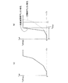
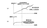
残り1系統の回転角センサ31(32)の出力信号を使って計算したモータ回転角θに基づいて操舵アシスト制御を行っている場合、残り1系統の回転角センサ31(32)が故障した場合には、操舵トルクTrに特有の変化が生じる。例えば、残り1系統の回転角センサ31(32)において、2つのMRセンサSc1,Ss1(Sc2,Ss2)の出力信号が同時に一定電圧に固着されてしまうという故障(信号固着故障と呼ぶ)が発生する場合が考えられる。その場合、図10(a)に示すように、故障が発生したタイミングで、計算されるモータ回転角θが一定となる。 When steering assist control is performed based on the motor rotation angle θ calculated using the output signal of the remaining one system of rotation angle sensor 31 (32), and when the remaining one system of rotation angle sensor 31 (32) fails In this case, a change peculiar to the steering torque Tr occurs. For example, in the remaining one system of rotation angle sensor 31 (32), a failure (referred to as signal fixation failure) occurs in which the output signals of the two MR sensors Sc1, Ss1 (Sc2, Ss2) are simultaneously fixed to a constant voltage. If you want to. In this case, as shown in FIG. 10A, the calculated motor rotation angle θ is constant at the timing when the failure occurs.
このため、モータ20が回転しているにもかかわらず、一定のモータ回転角θが通電制御部52に供給される。従って、モータ20の電気角を回転方向に進めることができず、操舵アシストトルクが減少する。その結果として、ドライバーは、無意識に操舵アシストトルクの減少を補うように操舵ハンドル11を操作する。これにより、トルクセンサ21によって検出される操舵トルクTrは、図10(b)に示すように急増する。
For this reason, although the
操舵トルクTrは、回転角センサ31(32)が正常であってモータ20の通電制御を適正に行っているときには、予め想定される大きさの範囲内に収まるが、回転角センサ31(32)に信号固着故障が発生してモータ回転角θが一定値に固定されてしまうと、想定範囲を超える。従って、こうした操舵トルクTrの特定の挙動(増加)を検出することにより、回転角センサ31(32)の信号固着故障が発生したことを判定することができる。
When the rotation angle sensor 31 (32) is normal and the energization control of the
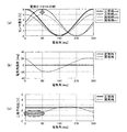
他の故障パターン例として、残り1つの回転角センサ31(32)において、電源電圧Vccが正常電圧よりも低い中間電圧に固着した故障(電源オフセット故障と呼ぶ)が発生する場合がある。その場合、図11(a)に示すように、回転角センサ31(32)の出力信号の電圧が変化する。この例では、電源電圧Vccが5Vから4Vに変化した例を表している。この場合、回転角センサ31(32)の出力信号は、振動の中点(原点)が2.5Vから2Vにずれ、振幅が2Vに変化する。これにより、計算される回転角(ここでは電気角で示している)は、図11(b)に示すように、誤差が発生する。 As another failure pattern example, in the remaining one rotation angle sensor 31 (32), a failure in which the power supply voltage Vcc is fixed to an intermediate voltage lower than the normal voltage (referred to as a power supply offset failure) may occur. In that case, as shown to Fig.11 (a), the voltage of the output signal of the rotation angle sensor 31 (32) changes. In this example, the power supply voltage Vcc is changed from 5V to 4V. In this case, the output signal of the rotation angle sensor 31 (32) shifts the midpoint (origin) of vibration from 2.5V to 2V and the amplitude changes to 2V. As a result, an error occurs in the calculated rotation angle (shown here as an electrical angle) as shown in FIG.
この誤差は、モータ20の回転に対して、電気角で360degを1周期として周期的に変動する。この場合、回転角センサ31(32)の出力電圧の二乗平均和Vxを計算すると、図11(c)に示すように、常に異常が検出されるというわけでなく、回転位置によっては異常が検出されない状況が発生する。この例では、図に破線で囲んだ領域においては、出力電圧の二乗平均和Vxが正常値から大きく外れるために、回転角センサの故障を確実に検出できるが、例えば、電気角で180deg、270deg近傍においては、故障を検出できない。従って、ドライバーが速いハンドル操作を行った場合には、出力電圧の二乗平均和を計算しても、故障検出をできないケースもある。
This error varies periodically with respect to the rotation of the
尚、2系統の回転角センサ31,32が正常である状態から電源オフセット故障が発生した場合には、それぞれの回転角センサ31,32の出力電圧の位相がπずれているため、それぞれの出力電圧の二乗平均和Vxが同時に正常値内に入ってしまう可能性は非常に小さい。従って、2系統の回転角センサ31,32が正常である状態から電源オフセット故障が発生した場合においては、迅速に故障検出できる。
When a power supply offset failure occurs when the two systems of
操舵中において、回転角センサ31(32)に電源オフセット故障が発生すると、図12(a)に示すように、計算されたモータ回転角θが周期的に真値からずれる。このため、モータ20にトルクリップルが発生する。例えば、モータ20の極対数を7,減速機25のギヤ比を18.5,操舵速度を90deg/秒とすると、トルクリップルの周波数は、32Hz(=7×18.5×90/360)となる。このトルクリップルに同期して、ドライバーが操舵ハンドル11に入力する操舵トルクが周期的に変動する。このような回転角センサ31(32)の電源オフセット故障に起因する操舵トルクの変動は、その周期が短く、ドライバーが操舵操作によって意図的に発生させることもなく、かつ、発生させることができるものでもない。このため、ドライバーの意図的な操舵操作による操舵トルクの振動とは、容易に区別することができる。
If a power supply offset failure occurs in the rotation angle sensor 31 (32) during steering, the calculated motor rotation angle θ is periodically deviated from the true value as shown in FIG. For this reason, torque ripple occurs in the
従って、こうした操舵トルクTrの周期的な変動を検出することにより、回転角センサ31(32)の電源オフセット故障が発生したことを判定することができる。この場合、操舵トルクの変動の周期が、電源オフセット故障時に想定される設定周期範囲に入っている場合に、回転角センサ31(32)の故障が発生したと判定すればよい。 Therefore, it is possible to determine that a power offset failure has occurred in the rotation angle sensor 31 (32) by detecting such periodic fluctuations in the steering torque Tr. In this case, it may be determined that a failure of the rotation angle sensor 31 (32) has occurred when the cycle of fluctuation of the steering torque is within the set cycle range assumed at the time of the power supply offset failure.
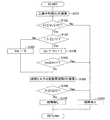
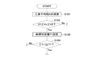
以下、2系統目故障検出部72における処理について説明する。図13は、2系統目故障検出部72の実施する2系統目故障判定ルーチンを表す。2系統目故障判定ルーチンは、所定の短い演算周期で繰り返し実施される。2系統目故障判定ルーチンは、後述する回転角故障対応制御ルーチン(図14)のステップS17として組み込まれたサブルーチンである。
Hereinafter, processing in the second system
2系統目故障判定ルーチンが起動すると、2系統目故障検出部72はステップS101において、残り1系統の回転角センサ31の検出信号Vsin1,Vcos1を読み込み、その出力電圧の二乗平均和Vx(=√(Vsin12+Vcos12)を計算する。ここでは、残り1系統の回転角センサ(1系統目故障検出部71によって故障が検出された系統とは異なる系統の回転角センサ)が第1回転角センサ31である場合を例として説明する。
When the second system failure determination routine is started, the second system
続いて、2系統目故障検出部72はステップS102において、二乗平均和Vxが許容範囲の下限値であるV1(=Vt−α)以上であって、許容範囲の上限値であるV2(=Vt+α)以下であるか否か、つまり、二乗平均和Vxが許容範囲内であるか否かを判断する。ここでαは、検出誤差等を考慮した許容値(α>0)である。二乗平均和Vxが許容範囲に入っていない場合、2系統目故障検出部72は、ステップS103において、当該回転角センサ31について故障有りと判定して、本ルーチンを一旦終了する。
Subsequently, in step S102, the second-system
一方、ステップS102において「Yes」と判定された場合、つまり、二乗平均和による判定では故障を検知できなかった場合、2系統目故障検出部72は、その処理をステップS104に進める。ステップS104からの処理は、操舵トルクTrの変動に基づいて、残り1系統の回転角センサ31の故障の有無を判定する処理である。つまり、二乗平均和では、回転角センサ31の故障を検出できないケースがあるため、それを担保するための処理である。
On the other hand, if it is determined as “Yes” in step S102, that is, if a failure cannot be detected by the determination based on the mean square sum, the second-system
2系統目故障検出部72は、ステップS104において、トルクセンサ21により検出される操舵トルクTrを読み込み、操舵トルクTrの大きさ|Tr|が予め設定された故障判定値T1以上であるか否かについて判断する。2系統目故障検出部72は、操舵トルク|Tr|が故障判定値T1以上である場合には、ステップS105において、タイマカウンタtimを値1だけインクリメントし、ステップS106において、タイマカウンタtimが設定値tim1以上に達したか否かを判断する。一方、操舵トルク|Tr|が故障判定値T1未満である場合には、2系統目故障検出部72は、ステップS107において、タイマカウンタtimの値をゼロクリアする。タイマカウンタtimの初期値はゼロに設定されている。これにより、タイマカウンタtimは、本ルーチンが繰り返されて、操舵トルク|Tr|が故障判定値T1以上であると判定されるたびにインクリメントされ、途中で操舵トルク|Tr|が故障判定値T1未満であると判定された場合にはゼロクリアされる。従って、このステップS104〜S107の処理は、操舵トルク|Tr|が故障判定値T1以上と判定されている継続時間が設定時間以上(設定値tim1に対応する時間)であるか否かについて判断する処理である。
In step S104, the second-system
2系統目故障検出部72は、操舵トルク|Tr|が故障判定値T1以上となっている継続時間が設定時間以上となったと判断した場合(S106:Yes)、その処理をステップS103に進めて、当該回転角センサ31について故障有りと判定する。回転角センサ31に信号固着故障が発生した場合には、上述したように、操舵トルクTrが急増する。従って、このステップS104〜S107の処理によって、信号固着故障を検出することができる。また、信号固着故障以外の原因、例えば、回転角センサ31の出力信号が反転する故障が発生したりして、二乗平均和では故障検出できなかった場合(S102:Yes)にも、操舵トルクTrが急増するため、回転角センサ31の故障を検出することができる。
If the second-system
一方、操舵トルク|Tr|が故障判定値T1以上となっている継続時間が設定時間未満であると判定された場合には、2系統目故障検出部72は、ステップS108において、操舵トルクTrの変動周波数fを演算する。例えば、2系統目故障検出部72は、操舵トルクTrをサンプリングして、直近の所定期間のサンプリング値から操舵トルクTrの周期的な変動成分を抽出し、その変動成分の変動周波数fを別途演算している。
On the other hand, if it is determined that the duration for which the steering torque | Tr | is equal to or greater than the failure determination value T1 is less than the set time, the second-system
続いて、2系統目故障検出部72は、ステップS109において、操舵トルクTrの変動周波数fが故障判定周波数範囲(f1〜f2)に入っているか否かについて判断する。操舵トルクTrは、電源オフセット故障が発生した場合には、特有の周波数(正常時には検出されない周波数)で振動する。2系統目故障検出部72は、電源オフセット故障に想定される操舵トルクTrの周波数範囲を故障判定周波数範囲(f1〜f2)として記憶しており、ステップS108で算出した操舵トルクTrの変動周波数fと、故障判定周波数範囲(f1〜f2)を比較する。
Subsequently, in step S109, the second system
2系統目故障検出部72は、操舵トルクTrの変動周波数fが故障判定周波数範囲(f1〜f2)に入っている場合(f1≦f≦f2)には、その処理をステップS103に進めて、当該回転角センサ31について故障有りと判定する。一方、操舵トルクTrに周期的な変動が発生していない、あるいは、発生していても変動周波数fが故障判定周波数範囲(f1〜f2)に入っていない場合には、ステップS110において、当該回転角センサ31について故障無しと判定する。
When the fluctuation frequency f of the steering torque Tr is within the failure determination frequency range (f1 to f2) (f1 ≦ f ≦ f2), the second-system
2系統目故障検出部72は、こうした処理を繰り返すことにより、残り1系統の回転角センサ31(32)の故障を判定する。従って、二乗平均和では検出できなかった故障に対しても検出することができる。
The second-system
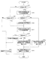
次に、回転角センサ31,32の故障に対する全体的な動作について説明する。図14は、回転角故障対応制御ルーチンを表す。本ルーチンは、主に、回転角センサ故障検出部70、モータ回転角演算部60、通電制御部52が協働して行う全体的な動作を示したものであるため、以下、アシスト演算部50の実施する処理として説明する。アシスト演算部50は、イグニッションスイッチがオンされている期間中、操舵アシスト制御と並行して回転角故障対応制御ルーチンを所定の短い周期で繰り返す。
Next, the overall operation for the failure of the
本ルーチンが起動されると、アシスト演算部50は、ステップS11において、2系統の回転角センサ31,32の両方ともが正常であるか(故障が検出されていないか)否かについて判断する。2系統の回転角センサ31,32に故障が検出されていない場合(S11:Yes)は、アシスト演算部50は、ステップS12において、1系統目故障検出部71による回転角センサ31,32の故障判定を上述したように操舵トルクTrを用いることなく実施する。
When this routine is started, the
一方、ステップS11において「No」と判定された場合には、アシスト演算部50は、ステップS21において、何れか一方の1系統の回転角センサ31(32)が正常であるか(故障が検出されていないか)否かについて判断する。1系統のみの回転角センサ31(32)に故障が検出されている場合には、アシスト演算部50は、ステップS17において、2系統目故障検出部72による回転角センサ31(32)の故障判定を実施する。このステップS17の処理は、上述した2系統目故障判定ルーチン(図13)と同一である。
On the other hand, if “No” is determined in step S11, the
また、ステップS21において「No」と判定された場合、つまり、2系統の回転角センサ31,32が何れも故障していると判定されている場合には、アシスト演算部50は、ステップS22において、操舵アシスト制御を停止する。
If it is determined as “No” in step S21, that is, if it is determined that both of the two
アシスト演算部50は、ステップS12において、1系統目故障検出部71による回転角センサ31,32の故障判定を実施した結果、故障有りと判定されなかった場合(S13:No)には、その処理をステップS14に進める。アシスト演算部50は、ステップS14において、正常時回転角演算部61により算出されたモータ回転角θを読み込み、ステップS15において、正常時回転角演算部61により算出されたモータ回転角θを使った操舵アシスト制御を継続する。
If the
一方、1系統の回転角センサ31(32)に故障有りと判定された場合(S13:Yes)には、ステップS16において、故障有りと特定された回転角センサ31(32)について、故障確定する。つまり、故障有りと特定された回転角センサ31に係る故障確定情報を記憶する。この故障確定情報によって、以降、ステップS11,S21の判断が決定される。アシスト演算部50は、ステップS16において、1系統の回転角センサ31(32)の故障を確定した後、その処理をステップS17に進める。
On the other hand, when it is determined that there is a failure in one system of rotation angle sensor 31 (32) (S13: Yes), in step S16, the failure is determined for the rotation angle sensor 31 (32) identified as having a failure. . That is, failure determination information related to the
アシスト演算部50は、ステップS17において、2系統目故障検出部72による回転角センサ31(32)の故障判定を実施した結果、故障有りと判定されなかった場合(S18:No)には、その処理をステップS19に進める。アシスト演算部50は、ステップS19において、1系統故障時回転角演算部62により算出されたモータ回転角θを読み込み、ステップS15において、1系統故障時回転角演算部62により算出されたモータ回転角θを使った操舵アシスト制御を継続する。従って2系統の回転角センサ31,32の一方の故障が検出されている状況であっても、残り1系統の回転角センサ31(32)の検出信号から算出されたモータ回転角θを使った操舵アシスト制御が継続される。
In step S17, the
また、アシスト演算部50は、ステップS17において2系統目故障検出部72による回転角センサ31(32)の故障判定を実施した結果、故障有りと判定された場合(S18:Yes)、ステップS20において、故障有りと特定された回転角センサ31(32)について故障確定情報を記憶する。続いて、アシスト演算部50は、ステップS22において、操舵アシスト制御を停止する。
In addition, when the
アシスト演算部50は、回転角故障対応制御ルーチンを所定の周期で繰り返す。従って、操舵アシスト制御中に、回転角センサ31,32の故障状況に応じた回転角センサ31,32の故障判定方法、および、モータ回転角θの計算に使用する回転角センサ31,32が選択され、2系統の回転角センサ31,32が両方とも故障するまで、回転角センサ31,32の検出信号を使った操舵アシスト制御を継続することができる。
The
以上説明した本実施形態の電動パワーステアリング装置1によれば、2系統目故障検出部72を設けて、1系統の回転角センサ31(32)が故障した場合には、それまでの故障判定方法を変更し、二乗平均和の値による判定に加えて、操舵トルクTrの特有な変動の有無に基づいた故障判定を追加している。これにより、二乗平均和では故障を検出できないケースであっても、故障を検出する可能性を高めることができる。
According to the electric
また、操舵トルクTrの変動は、回転角センサ31,32が故障した場合だけでなく他の要因にても発生する。そこで、2系統の回転角センサ31,32が両方とも故障が検出されていない状況においては、操舵トルクTrの変動に基づく故障判定を行わないようにし、残り1系統の回転角センサ31(32)により検出されるモータ回転角を使ったアシスト制御時においてのみ、操舵トルクTrの特有な変動に基づいた故障判定を追加している。従って、回転角センサ31,32の故障以外の要因による操舵トルクTrの変動に関しては、誤って回転角センサ31,32の故障であると誤判定しないように最大限配慮されている。
Further, the fluctuation of the steering torque Tr occurs not only when the
更に、電源オフセット故障、および、信号固着故障は、それぞれ特有の操舵トルクTrの挙動を生じるため、回転角センサ31,32の故障モードと操舵トルクTrの挙動とに強い相関がある。このため、電源オフセット故障時、および、信号固着故障時に特有に生じる操舵トルクの挙動に基づいて、故障判定閾値(故障判定値T1、故障判定周波数f1〜f2)を設定して、故障判定を行っているため、誤検出の可能性を小さくすることができる。つまり、操舵トルク|Tr|が故障判定値T1以上と判定されている継続時間が設定時間以上である、あるいは、操舵トルクTrの変動周波数fが故障判定周波数範囲(f1〜f2)に入っている場合に限って、故障有りと判定しているため、誤検出の可能性を小さくすることができる。つまり、他の要因で操舵トルクTrが変動した場合には、回転角センサ31,32の故障であると誤判定する可能性を小さくすることができる。
Furthermore, since the power supply offset failure and the signal fixing failure each have a specific behavior of the steering torque Tr, there is a strong correlation between the failure mode of the
これらの結果、2系統の回転角センサ31,32を有効利用して、精度の良い操舵アシスト制御を継続させることができる。これにより、ドライバーは、長期にわたって良好な操舵アシストを得ることができる。
As a result, the steering assist control with high accuracy can be continued by effectively using the two
次に、いくつかの変形例について説明する。
<センサレス制御の適用>
上記実施形態においては、2系統の回転角センサ31,32の両方に故障が検出されている状況においては、ステップS22において、操舵アシストを停止するが、それに代えて、モータ20のセンサレス制御により操舵アシストを実施するようにしてもよい。モータ20のセンサレス制御は、モータ20の電気角を推定し、その推定した電気角に基づいてモータ20を駆動制御する公知の手法である。例えば、本願出願人は、センサレス制御にて電動パワーステアリング装置のモータを駆動する技術を特開2012−166776等に提案しており、こうした技術などを使用することができる。
Next, some modifications will be described.
<Application of sensorless control>
In the above embodiment, in the situation where a failure is detected in both of the two
この場合、アシスト演算部50は、図4に破線で示すように、センサレス電気角推定部80を備えている。センサレス電気角推定部80は、電流センサ41により検出されるモータ電流Imと、電圧センサ42により検出される端子電圧Vmとを読み込み、このモータ電流Imと端子電圧Vmとに基づいて、誘起電圧(逆起電力)を演算し、誘起電圧に比例するモータ角速度ωを算出する。そして、誘起電圧の演算周期と角速度とから、1演算周期あたりにモータ20が回転した回転角度を演算し、1演算周期前の電気角に、この回転角度を加減算することにより現時点の電気角、つまり、推定電気角θeを演算する。通電制御部52は、この推定電気角θeを使ってモータ20を駆動制御する。
In this case, the
電気角の推定は、回転角センサ31(32)を使って実際にモータ20の回転角を検出する場合に比べて検出精度が劣る。そこで、この変形例では、2系統の回転角センサ31,32を有効利用して、精度の良い操舵アシスト制御を継続させ、2系統の回転角センサ31,32の両方の故障が検出された時点で、ステップS22においてセンサレス制御に切り替えられる。従って、できるだけ操舵アシストを延命させることができ、ドライバーの負担を軽減することができる。
The estimation of the electrical angle is inferior in detection accuracy compared to the case of actually detecting the rotation angle of the
<故障判定閾値の変形例>
上記実施形態においては、2系統目故障検出部72が、ステップS104〜S107において、操舵トルク|Tr|が予め設定された故障判定値T1以上となっている継続期間が設定時間以上である場合に、回転角センサ31(32)が故障していると判定する。この場合、故障判定値T1が小さいと、実際には回転角センサ31(32)が故障していなくても故障していると誤判定しやすく、逆に、故障判定値T1が大きいと、回転角センサ31,32の故障検出精度が低下する。そこで、こうした点を改良する3つの変形例について説明する。3つの変形例は、図15に示すように、2系統目故障検出部72が、ステップS104の判断処理を行う前に、ステップS120において、故障判定値T1を状況に応じて設定する処理を追加したものである。
<Modification of failure determination threshold>
In the above embodiment, when the second system
<故障判定閾値の変形例1>
例えば、据え切り操舵時、極低速走行中の操舵時においては、軸力が大きく、ドライバーが操舵ハンドル11に入力する操作力が増加しやすい。そこで、この変形例1においては、2系統目故障検出部72が、ステップS120において、車速センサ23により検出される車速Vを読み込み、この車速Vに応じて故障判定値T1を設定する。例えば、2系統目故障検出部72は、図16の故障判定値設定マップに示すように、車速Vがゼロから設定速度V1(極低速速度)の範囲(低車速範囲と呼ぶ)に入る場合は、車速Vが低車速範囲に入らない場合に比べて大きな故障判定値T1を設定する。そして、2系統目故障検出部72は、ステップS104において、この故障判定値T1を使って操舵トルク|Tr|と比較する。
<
For example, at the time of stationary steering or during steering at extremely low speed, the axial force is large, and the operating force input to the steering handle 11 by the driver tends to increase. Therefore, in the first modification, the second-system
この故障判定値設定マップでは、故障判定値T1を2段階に変更しているが、車速Vが低い場合には高い場合に比べて、故障判定値T1が大きな値に設定されるものであればよく、複数段階、あるいは、連続的に変更するものであってもよい。この変形例1によれば、残り1系統の回転角センサ31の故障検出精度を維持しつつ、故障検出に係る誤判定を低減することができる。
In this failure judgment value setting map, the failure judgment value T1 is changed in two stages. However, if the vehicle speed V is low, the failure judgment value T1 is set to a larger value than when it is high. It may be a plurality of steps or may be changed continuously. According to the first modification, it is possible to reduce erroneous determination related to failure detection while maintaining the failure detection accuracy of the remaining one
<故障判定閾値の変形例2>
一般に、電動パワーステアリング装置は、モータの出力を制限する機能を備えている。例えば、モータの過熱するおそれがある場合には、モータの出力が制限される。本実施形態の電動パワーステアリング装置1においても、モータ20の出力制限機能を備えている。例えば、アシスト演算部50は、モータ20の温度を検出、あるいは、推定することによって、モータ20が過熱するおそれのある場合には、モータ20に流す電流の上限値を下げることによって、モータ20の過熱防止を図る。こうしたモータ20の出力制限が働いている状況、つまり、出力制限モードが設定されている状況においては、操舵アシストトルクが通常時(モータの出力制限が働いていない時)に比べて制限される。このため、ドライバーの操舵ハンドルに入力する操舵トルクが増加しやすい。
<Modification Example 2 of Failure Determination Threshold>
In general, the electric power steering apparatus has a function of limiting the output of the motor. For example, when there is a possibility of overheating of the motor, the output of the motor is limited. The electric
そこで、この変形例2においては、2系統目故障検出部72が、ステップS120において、モータ20の出力制限が働いている状況(出力制限モード)か否かを判断し、モータ20の出力制限が働いている状況であれば、出力制限が働いていない状況に比べて、大きな故障判定値T1を設定する。従って、この変形例2においても、残り1系統の回転角センサ31(32)の故障検出精度を維持しつつ、故障検出に係る誤判定を低減することができる。
Therefore, in the second modification, the second system
<故障判定閾値の変形例3>
ステアリング機構10には、右方向および左方向の操舵操作の限界位置を設定するストッパが設けられている。この操舵操作の限界位置をストロークエンドと呼ぶ。操舵ハンドル11を大きく操舵操作して操舵位置がストロークエンドに到達した場合には、操舵ハンドル11をそれ以上回すことができなくなり、操舵トルクTrが急激に増加する可能性がある。
<Modification 3 of failure determination threshold>
The
そこで、この変形例3においては、2系統目故障検出部72が、ステップS120において、操舵角センサ22により検出される操舵角θhを読み込み、この操舵角θhに基づいて故障判定値T1を設定する。例えば、2系統目故障検出部72は、操舵角θhが最大舵角近傍(操舵操作位置がストロークエンド近傍)であるか否かを判断し、操舵角θhが最大舵角近傍である場合には、最大舵角近傍でない場合に比べて大きな故障判定値T1を設定する。従って、この変形例3においても、残り1系統の回転角センサ31の故障検出精度を維持しつつ、故障検出に係る誤判定を低減することができる。尚、操舵角θhが最大舵角近傍であるか否かの判断は、例えば、操舵角θhが最大舵角θmaxから所定範囲γ内(θmax−γ≦|θh|≦θmax)に入っているか否かについて判断すればよい。
Therefore, in the third modification, the second system
<故障確定に係る変形例1>
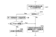
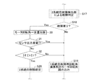
上述した実施形態においては、2系統目故障検出部72による回転角センサ31(32)の故障判定を実施した結果、故障有りと判定された時点(操舵トルク|Tr|が故障判定値T1以上と判定されている継続時間が設定時間以上であるか、あるいは、操舵トルクTrの変動周波数fが故障判定周波数範囲(f1〜f2)に入っていると判定された時点)で、故障が確定された(S20)。この変形例においては、故障を確定するに当たって、更に、以下の処理を追加している。
<
In the embodiment described above, when the failure determination of the rotation angle sensor 31 (32) by the second-system
図17は、故障確定に係る変形例1に係る処理を表す。この変形例1は、実施形態の回転角故障対応制御ルーチンにステップS30,S31の処理を追加したものである。アシスト演算部50は、回転角故障対応制御ルーチンのステップS18において、2系統目故障検出部72によって故障有りと判定された場合、ステップS30において、操舵トルクTrの符号と同じ方向に、モータ回転角θに所定回転角だけ加算する。これにより、通電制御部52においては、その加算量に対応した量だけモータ20の電気角を進める。従って、モータ20の出力する操舵アシストトルクが変化し、それに応答してドライバーが操舵ハンドル11を回転させる。尚、所定回転角の加算は、操舵トルクTrの符号と同じ方向に限らず、反対方向であってもよい。
FIG. 17 illustrates processing according to the first modification example related to failure confirmation. In the first modification, the processes of steps S30 and S31 are added to the rotation angle failure handling control routine of the embodiment. In step S18 of the rotation angle failure handling control routine, the
このとき、残り1系統の回転角センサ31(32)が故障していなければ、回転角センサ31(32)の出力する電圧信号は変化するはずである。そこで、アシスト演算部50は、ステップS31において、回転角センサ31(32)の出力する電圧信号を読み込み、電圧信号に変動があったか否かを判断する。アシスト演算部50は、電圧信号に変動が無い場合には、ステップS20において、残り1系統の回転角センサ31(32)についても故障を確定する。一方、電圧信号に変動があった場合には、アシスト演算部50は、残り1系統の回転角センサ31(32)の故障を確定することなく、その処理をステップS19に進める。
At this time, if the remaining one rotation angle sensor 31 (32) has not failed, the voltage signal output from the rotation angle sensor 31 (32) should change. Therefore, in step S31, the
この故障確定に係る変形例1によれば、2系統目故障検出部72によって故障有りと判定されても直ちに故障を確定せずに、モータ20の電気角を進めてドライバーに操舵ハンドル11を回転操作させた後に、回転角センサ31(32)の故障の有無を再度判定する。従って、残り1系統の回転角センサ31(32)の故障検出精度を維持しつつ、故障検出に係る誤判定を低減することができる。
According to the first modification related to the failure confirmation, even if it is determined by the second system
<故障確定に係る変形例2>
例えば、操舵ハンドル11を回転できない状況(操舵角がエンド位置に到達している状況、転舵輪Wが轍にはまっている状況など)においては、モータ回転角θに所定回転角だけ加算しても、回転角センサ31の出力する電圧信号は変化しない可能性がある。そこで、この故障確定に係る変形例2においては、図18に示すように、故障確定に係る変形例1に対して、ステップS32の判断処理が追加されている。
<
For example, in a situation where the
アシスト演算部50は、ステップS31において、残り1系統の回転角センサ31(32)の出力する電圧信号が変化しないと判定した場合、その処理をステップS32に進める。アシスト演算部50は、ステップS32において、電流センサ41により検出されるモータ電流Imと、電圧センサ42により検出される端子電圧Vmとを読み込み、このモータ電流Imと端子電圧Vmとに基づいて、モータ20で発生する誘起電圧(逆起電力)Eを演算する。そして、誘起電圧Eの大きさ|E|が車輪ロック判定閾値E1よりも大きいか否かについて判断する。
If the
車輪ロック判定閾値E1は、転舵輪Wがロックしているか否かを判定するために予め設定された閾値である。誘起電圧|E|が車輪ロック判定閾値E1以下となる場合には、転舵輪Wがロックしていると推定できるため、アシスト演算部50は、「No」と判定して、その処理をステップS19に進める。従って、この場合には、残り1系統の回転角センサ31(32)の故障は確定されない。一方、誘起電圧|E|が車輪ロック判定閾値E1よりも大きい場合には、転舵輪Wがロックしていないと推定できるため、アシスト演算部50は、「Yes」と判定して、その処理をステップS20に進める。従って、この場合には、残り1系統の回転角センサ31についても故障が確定する。
The wheel lock determination threshold E1 is a threshold set in advance to determine whether or not the steered wheel W is locked. When the induced voltage | E | is equal to or less than the wheel lock determination threshold value E1, it can be estimated that the steered wheel W is locked. Therefore, the
この故障確定に係る変形例2によれば、変形例1の作用効果に加えて、操舵ハンドル11を回転できない状況における、回転角センサ31(32)の故障検出に係る誤判定を低減することができる。 According to the second modification related to the failure confirmation, in addition to the operational effects of the first modification, it is possible to reduce the erroneous determination related to the failure detection of the rotation angle sensor 31 (32) in a situation where the steering handle 11 cannot be rotated. it can.
<アシスト特性に係る変形例>
上記実施形態においては、2系統目故障検出部72が、ステップS104〜S107において、操舵トルク|Tr|が予め設定された故障判定値T1以上となっている継続期間が設定時間以上である場合に、回転角センサ31(32)が故障していると判定する。よって、残りの1系統の回転角センサ32(31)が故障していない場合は、できるだけ操舵トルク|Tr|が故障判定値T1以上にならないようにすることにより誤判定の可能性を低減できる。そこで、この変形例では、アシスト特性を、2系統の回転角センサ31,32がともに正常である場合(故障が検出されていない場合)と、1系統の回転角センサ31(32)に故障が検出されている場合とで切り替える。
<Modifications related to assist characteristics>
In the above embodiment, when the second system
図5(a)は、正常時アシスト特性を示し、図5(b)は、1系統故障時アシスト特性を示す。モータ制御量演算部51は、回転角センサ故障検出部70から出力される故障検出信号Failを入力し、2系統の回転角センサ31,32の故障状況を判断する。モータ制御量演算部51は、2系統の回転角センサ31,32がともに正常である場合には、正常時アシスト特性を使って操舵トルクTrに応じた目標アシストトルクTa*を演算し、1系統の回転角センサ31(32)に故障が検出されている場合には、1系統故障時アシスト特性を使って操舵トルクTrに応じた目標アシストトルクTa*を演算する。
FIG. 5A shows the normal assist characteristics, and FIG. 5B shows the one-system fault assist characteristics. The motor control
1系統故障時アシスト特性においては、正常時アシスト特性に比べて、操舵トルク|Tr|が所定値よりも大きい範囲において、操舵トルク|Tr|の増加に対する目標アシストトルクTa*の増加度合が大きくなっており、操舵トルク|Tr|に対する目標アシストトルクTa*が大きな値に設定される。このため、1系統故障時アシスト特性においては、正常時アシスト特性に比べて、小さな操舵トルク|Tr|で目標アシストトルクTa*が上限値に達する。従って、ハンドル操作が軽い設定になっている。 In the one-system failure assist characteristic, the degree of increase in the target assist torque Ta * with respect to the increase in the steering torque | Tr | is larger in the range where the steering torque | Tr | is larger than the predetermined value compared with the normal assist characteristic. The target assist torque Ta * with respect to the steering torque | Tr | is set to a large value. Therefore, in the one-system failure assist characteristic, the target assist torque Ta * reaches the upper limit value with a small steering torque | Tr | as compared with the normal assist characteristic. Accordingly, the handle operation is lightly set.
1系統故障時アシスト特性においては、回転角センサ31,32の故障判定に用いられる故障判定値T1は、目標アシストトルクTa*が上限値Ta*maxに到達するときの操舵トルクTmaxよりも大きな値に設定されている。このように設定することにより、ドライバーは、通常、目標アシストトルクTa*が上限値Ta*max以下となる範囲の操舵トルクにて操舵ハンドル11を操作する。従って、1系統故障時アシスト特性を用いて操舵アシスト制御が実施されている場合には、操舵トルク|Tr|は、故障判定値T1よりも小さくなる。
In the one-system failure assist characteristic, the failure determination value T1 used for failure determination of the
このアシスト特性に係る変形例によれば、残り1系統の回転角センサ31(32)の故障検出精度を維持しつつ、故障検出に係る誤判定を低減することができる。 According to the modification related to the assist characteristics, it is possible to reduce erroneous determinations related to failure detection while maintaining the failure detection accuracy of the remaining one system of rotation angle sensors 31 (32).
以上、本実施形態および変形例にかかる車両の電動パワーステアリング装置1について説明したが、本発明は上記実施形態および変形例に限定されるものではなく、本発明の目的を逸脱しない限りにおいて種々の変更が可能である。
As mentioned above, although the electric
例えば、本実施形態においては、MRセンサの出力信号に基づいてモータ回転角θを検出する回転角検出手段を備えているが、回転角検出手段は、必ずしもMRセンサを備えている必要はなく、他のセンサを用いたものであってもよい。 For example, in the present embodiment, the rotation angle detection unit that detects the motor rotation angle θ based on the output signal of the MR sensor is provided. However, the rotation angle detection unit does not necessarily include the MR sensor. Another sensor may be used.
また、実施形態に故障判定閾値の変形例1,2,3を適宜組み合わせて実施する構成であってもよい。つまり、車速条件、出力制限モード条件、操舵角条件を任意に組み合わせたOR条件を使って、故障判定値T1を設定する構成であってもよい。
Moreover, the structure which implements combining
また、故障確定に係る変形例1,2についても、実施形態に限らず、故障判定閾値の変形例1,2,3と適宜組み合わせることも可能である。また、アシスト特性に係る変形例についても、実施形態に限らず、故障判定閾値の変形例1,2,3、および、故障確定に係る変形例1,2と適宜組み合わせることも可能である。 Further, the first and second modifications related to failure determination are not limited to the embodiment, and can be appropriately combined with the first, second, and third modifications of the failure determination threshold. Further, the modified example related to the assist characteristic is not limited to the embodiment, and can be appropriately combined with the modified examples 1, 2, and 3 of the failure determination threshold and the modified examples 1 and 2 related to the failure determination.
また、本実施形態においては、回転角検出手段(回転角センサユニット30)は、モータ20のロータの回転角を直接検出するが、それに代えて、モータ20の回転と共に回転する部材、例えば、ピニオンシャフト12cあるいはインターミディエイトシャフト12bなどの部材の回転角を検出する構成であってもよい。
In the present embodiment, the rotation angle detection means (the rotation angle sensor unit 30) directly detects the rotation angle of the rotor of the
また、本実施形態においては、モータ20の発生するトルクをステアリングシャフト12に付与するコラムアシスト式の電動パワーステアリング装置について説明したが、モータの発生するトルクをラックバー14に付与するラックアシスト式の電動パワーステアリング装置であってもよい。
In the present embodiment, the column assist type electric power steering device that applies the torque generated by the
1…電動パワーステアリング装置、10…ステアリング機構、11…操舵ハンドル、20…モータ、21…トルクセンサ、22…操舵角センサ、23…車速センサ、30…回転角センサユニット、31,32…回転角センサ、40…モータ駆動回路、41…電流センサ、42…電圧センサ、50…アシスト演算部、51…モータ制御量演算部、52…通電制御部、60…モータ回転角演算部、61…正常時回転角演算部、62…1系統故障時回転角演算部、63…回転角出力部、70…回転角センサ故障検出部、71…1系統目故障検出部、72…2系統目故障検出部、73…故障信号出力部、80…センサレス電気角推定部、100…アシストECU、Ele1,Ele2…エレメント、f…変動周波数、Fail…故障検出信号、Ss1,Sc1,Ss2,Sc2…磁気センサ、T1…故障判定値、Tr…操舵トルク、Vsin1,Vcos1,Vsin2,Vcos2…検出信号(出力電圧)、Vx…二乗平均和、θ…モータ回転角、θh…操舵角。
DESCRIPTION OF
Claims (9)
ステアリング機構に設けられて操舵アシストトルクを発生するモータと、
2系統の回転角センサを有し、前記2系統の回転角センサの少なくとも一方の出力信号を用いて、前記モータの回転角を検出する回転角検出手段と、
前記トルク検出手段により検出された操舵トルクに基づいて目標操舵アシストトルクを発生させるためのモータ制御値を演算するモータ制御値演算手段と、
前記回転角検出手段により検出された回転角と前記モータ制御値演算手段により演算された前記モータ制御値とに基づいて、前記モータを駆動制御するモータ制御手段と
を備えた車両の電動パワーステアリング装置において、
前記2系統の回転角センサに対して故障が発生したか否かについて、すでに回転角センサの故障が1系統だけ検出されている状況であるのか、1系統も検出されていない状況であるのかに応じて互いに異なる故障判定方法を用いて判定するセンサ故障判定手段を備え、
前記モータ制御手段は、前記回転角センサの故障が1系統だけ検出されている状況においては、故障が検出されていない残り1系統の回転角センサにより検出された回転角に基づいて前記モータの駆動制御を継続し、
前記センサ故障判定手段は、前記回転角センサの故障が1系統だけ検出されている状況で前記残り1系統の回転角センサに故障が発生したか否かについて判定する場合に限って、前記トルク検出手段によって検出された操舵トルクが、前記残り1系統の回転角センサが故障した場合に想定される特定の挙動を示したか否かに基づいて、前記故障発生の有無を判定する判定処理を含むように構成された、車両の電動パワーステアリング装置。 Torque detecting means for detecting steering torque input from the steering handle to the steering shaft;
A motor provided in the steering mechanism for generating steering assist torque;
A rotation angle detecting means having two rotation angle sensors, and detecting the rotation angle of the motor using an output signal of at least one of the two rotation angle sensors;
Motor control value calculating means for calculating a motor control value for generating a target steering assist torque based on the steering torque detected by the torque detecting means;
An electric power steering apparatus for a vehicle, comprising: motor control means for driving and controlling the motor based on the rotation angle detected by the rotation angle detection means and the motor control value calculated by the motor control value calculation means. In
Whether or not a failure has occurred in the two systems of rotation angle sensors, whether a rotation angle sensor failure has already been detected or whether only one system has been detected. Sensor failure determination means for determining using a different failure determination method according to each other,
In a situation where only one system has detected a failure of the rotation angle sensor, the motor control means drives the motor based on the rotation angle detected by the remaining one system of rotation angle sensors in which no failure has been detected. Continue control,
The sensor failure determination means is configured to detect the torque only when determining whether or not a failure has occurred in the remaining one rotation angle sensor in a situation where only one rotation angle sensor failure has been detected. A determination process for determining whether or not the failure has occurred, based on whether or not the steering torque detected by the means exhibits a specific behavior assumed when the remaining one system of rotation angle sensors fails. An electric power steering device for a vehicle configured as described above.
前記特定の挙動は、前記操舵トルクが予め設定された故障判定値以上となる継続時間が設定時間以上となる挙動を含む、車両の電動パワーステアリング装置。 The electric power steering device for a vehicle according to claim 1,
The electric power steering apparatus for a vehicle, wherein the specific behavior includes a behavior in which a duration for which the steering torque is equal to or greater than a preset failure determination value is equal to or longer than a set time.
前記車両の速度である車速が遅い場合には、前記車速が速い場合に比べて前記故障判定値を大きくする車速応答故障判定値設定手段を備えた車両の電動パワーステアリング装置。 The electric power steering device for a vehicle according to claim 2,
An electric power steering apparatus for a vehicle, comprising vehicle speed response failure determination value setting means for increasing the failure determination value when the vehicle speed, which is the vehicle speed, is slow compared to when the vehicle speed is high.
前記モータ制御手段が前記モータの出力制限をする出力制限モードにて動作している場合には、前記出力制限モードにて動作していない場合に比べて前記故障判定値を大きくする出力制限応答故障判定値設定手段を備えた車両の電動パワーステアリング装置。 In the electric power steering device for a vehicle according to claim 2 or 3,
When the motor control unit is operating in the output limit mode that limits the output of the motor, the output limit response failure that increases the failure determination value compared to when not operating in the output limit mode An electric power steering device for a vehicle comprising a judgment value setting means.
前記操舵ハンドルが操舵限界位置から所定範囲内に位置する場合には、前記操舵ハンドルが前記操舵限界位置から所定範囲内に位置しない場合に比べて前記故障判定値を大きくする操舵位置応答故障判定値設定手段を備えた車両の電動パワーステアリング装置。 In the electric power steering device for a vehicle according to any one of claims 2 to 4,
When the steering handle is positioned within a predetermined range from the steering limit position, a steering position response failure determination value that increases the failure determination value compared to when the steering handle is not positioned within the predetermined range from the steering limit position An electric power steering device for a vehicle comprising setting means.
前記センサ故障判定手段は、前記操舵トルクが予め設定された故障判定値以上となる継続時間が設定時間以上となる挙動が検出された場合、前記モータ制御手段が前記モータを駆動制御するために用いる回転角に所定回転角を加算し、前記所定回転角の加算後に、前記回転角検出手段によって検出される回転角の変化が生じない場合に、前記残り1系統の回転角センサが故障したことを確定するように構成された車両の電動パワーステアリング装置。 The electric power steering device for a vehicle according to any one of claims 2 to 5,
The sensor failure determination unit is used by the motor control unit to drive and control the motor when a behavior in which a duration time during which the steering torque is equal to or greater than a predetermined failure determination value is detected is equal to or longer than a set time is detected. When a predetermined rotation angle is added to the rotation angle, and no change in the rotation angle detected by the rotation angle detection means occurs after the addition of the predetermined rotation angle, the remaining one rotation angle sensor has failed. An electric power steering device for a vehicle configured to be fixed.
前記センサ故障判定手段は、前記所定回転角の加算後に、前記回転角検出手段によって検出される回転角の変化が生じなく、かつ、前記モータで発生する誘起電圧の大きさが前記モータの回転状態を判定する設定電圧より大きい場合に、前記残り1系統の回転角センサが故障したことを確定するように構成された車両の電動パワーステアリング装置。 The electric power steering device for a vehicle according to claim 6,
The sensor failure determination means does not cause a change in the rotation angle detected by the rotation angle detection means after the addition of the predetermined rotation angle, and the magnitude of the induced voltage generated in the motor is the rotation state of the motor. The electric power steering device for a vehicle configured to determine that the remaining one system of rotation angle sensors has failed when the voltage is larger than a set voltage for determining.
前記モータ制御値演算手段は、前記センサ故障判定手段によって1系統の回転角センサの故障が検出されている場合には、2系統ともに回転角センサの故障が検出されていない場合に比べて、前記操舵トルクに対する前記目標操舵アシストトルクの大きさを大きくするように構成された車両の電動パワーステアリング装置。 The electric power steering apparatus for a vehicle according to any one of claims 1 to 7,
The motor control value calculation means is more effective when the failure of one rotation angle sensor is detected by the sensor failure determination means than when no rotation angle sensor failure is detected in both systems. An electric power steering apparatus for a vehicle configured to increase a magnitude of the target steering assist torque with respect to a steering torque.
前記2系統の回転角センサは、それぞれ、2つの磁気センサを備え、
前記2つの磁気センサは、それぞれ、電源回路から電圧が印加される直列に接続された2つの磁気抵抗効果素子を備え、前記2つの磁気抵抗効果素子の接続点の電圧信号であって、前記モータの回転に伴って正弦波状に変化し、互いに位相がπ/2だけずれた振幅の等しい電圧信号を出力するように構成され、
前記特定の挙動は、前記操舵トルクが予め設定された周波数範囲で周期的に変化する挙動を含む、車両の電動パワーステアリング装置。 The electric power steering apparatus for a vehicle according to any one of claims 1 to 8,
Each of the two systems of rotation angle sensors includes two magnetic sensors,
Each of the two magnetic sensors includes two magnetoresistive elements connected in series to which a voltage is applied from a power supply circuit, and is a voltage signal at a connection point of the two magnetoresistive elements, the motor Is changed to a sinusoidal waveform with the rotation of, and is configured to output voltage signals of equal amplitude with phases shifted from each other by π / 2,
The specific behavior includes a behavior in which the steering torque periodically changes in a preset frequency range.
Priority Applications (4)
| Application Number | Priority Date | Filing Date | Title |
|---|---|---|---|
| JP2014253575A JP6083428B2 (en) | 2014-12-16 | 2014-12-16 | Electric power steering device for vehicle |
| US14/961,100 US9663140B2 (en) | 2014-12-16 | 2015-12-07 | Electric power steering system for vehicle |
| CN201510903674.7A CN105691444B (en) | 2014-12-16 | 2015-12-09 | Electric power steering for vehicle |
| DE102015121717.1A DE102015121717B4 (en) | 2014-12-16 | 2015-12-14 | Electric power steering system for a vehicle |
Applications Claiming Priority (1)
| Application Number | Priority Date | Filing Date | Title |
|---|---|---|---|
| JP2014253575A JP6083428B2 (en) | 2014-12-16 | 2014-12-16 | Electric power steering device for vehicle |
Publications (2)
| Publication Number | Publication Date |
|---|---|
| JP2016113031A JP2016113031A (en) | 2016-06-23 |
| JP6083428B2 true JP6083428B2 (en) | 2017-02-22 |
Family
ID=56082636
Family Applications (1)
| Application Number | Title | Priority Date | Filing Date |
|---|---|---|---|
| JP2014253575A Active JP6083428B2 (en) | 2014-12-16 | 2014-12-16 | Electric power steering device for vehicle |
Country Status (4)
| Country | Link |
|---|---|
| US (1) | US9663140B2 (en) |
| JP (1) | JP6083428B2 (en) |
| CN (1) | CN105691444B (en) |
| DE (1) | DE102015121717B4 (en) |
Families Citing this family (29)
| Publication number | Priority date | Publication date | Assignee | Title |
|---|---|---|---|---|
| JP6380014B2 (en) * | 2014-11-04 | 2018-08-29 | 株式会社ジェイテクト | Electric power steering device |
| JP6083428B2 (en) * | 2014-12-16 | 2017-02-22 | トヨタ自動車株式会社 | Electric power steering device for vehicle |
| DE102015116438B4 (en) | 2015-09-29 | 2023-03-30 | Robert Bosch Gmbh | Method and device for operating a power steering system, power steering system |
| DE102016103518A1 (en) * | 2016-02-29 | 2017-08-31 | Robert Bosch Automotive Steering Gmbh | Method and device for rotor position diagnosis in an electric motor drive |
| GB2549328A (en) * | 2016-04-15 | 2017-10-18 | Jaguar Land Rover Ltd | Vehicle steering system |
| US11237021B2 (en) * | 2016-04-28 | 2022-02-01 | Mitsubishi Electric Corporation | Failure determination device for rotating machine control device and failure determination method |
| JP6319538B1 (en) * | 2016-07-20 | 2018-05-09 | 日本精工株式会社 | Rotation angle detector and torque sensor |
| KR101835406B1 (en) * | 2016-08-26 | 2018-03-09 | 현대모비스 주식회사 | Motor driven power steering control apparatus |
| JP6747367B2 (en) * | 2017-04-18 | 2020-08-26 | 株式会社デンソー | Rudder angle detection device and electric power steering device using the same |
| KR101950259B1 (en) * | 2017-05-22 | 2019-02-22 | 주식회사 만도 | Apparatus and Method for Detecting Steering Information of Electric Power Steering Device |
| JP6228341B1 (en) * | 2017-05-26 | 2017-11-08 | 株式会社ショーワ | Failure detection device, electric power steering device |
| DE102017116764A1 (en) * | 2017-07-25 | 2019-01-31 | Danfoss Power Solutions Aps | Steering wheel angle sensor and method for detecting errors in a steering wheel angle sensor |
| DE102017215842A1 (en) * | 2017-09-08 | 2019-03-14 | Robert Bosch Gmbh | Method for operating a steering device and steering device |
| KR101901127B1 (en) | 2017-09-29 | 2018-09-27 | 주식회사 만도 | Apparatus and method for detecting a faulty motor |
| KR102024550B1 (en) * | 2017-10-16 | 2019-09-24 | 주식회사 만도 | Fail Safe Control Apparatus For Electric Power Steering System And Method Thereof |
| JP6911714B2 (en) * | 2017-11-07 | 2021-07-28 | 株式会社ジェイテクト | Steering control device |
| JP6922669B2 (en) * | 2017-11-07 | 2021-08-18 | 株式会社ジェイテクト | Steering control device |
| JP6965697B2 (en) | 2017-11-09 | 2021-11-10 | 株式会社ジェイテクト | Steering control device |
| US11529990B2 (en) | 2018-03-20 | 2022-12-20 | Denso Corporation | Signal control apparatus and electric power steering apparatus using same |
| JP7106989B2 (en) * | 2018-03-20 | 2022-07-27 | 株式会社デンソー | SIGNAL CONTROL DEVICE AND ELECTRIC POWER STEERING DEVICE USING THE SAME |
| CN108945091B (en) * | 2018-07-26 | 2020-03-24 | 北京新能源汽车股份有限公司 | Steering control method and device, electric power steering system controller and automobile |
| US11654958B2 (en) | 2018-10-12 | 2023-05-23 | Robert Bosch Gmbh | Detecting impact forces on an electric power steering system |
| CN109552403A (en) * | 2018-11-28 | 2019-04-02 | 安徽德孚转向系统股份有限公司 | The Transducer-fault Detecting Method of electric boosting steering system |
| JP6811820B1 (en) * | 2019-09-27 | 2021-01-13 | 三菱電機株式会社 | Motor control device |
| CN111293928A (en) * | 2020-01-23 | 2020-06-16 | 中国公路车辆机械有限公司 | EPS motor position detection system and method based on TMR element |
| US11708105B2 (en) | 2020-02-11 | 2023-07-25 | Robert Bosch Gmbh | Detecting damage to components of an electric power steering system |
| US11608109B2 (en) | 2020-08-12 | 2023-03-21 | Analog Devices International Unlimited Company | Systems and methods for detecting magnetic turn counter errors with redundancy |
| US11493362B2 (en) | 2020-08-12 | 2022-11-08 | Analog Devices International Unlimited Company | Systems and methods for detecting magnetic turn counter errors |
| US11919580B2 (en) * | 2021-12-09 | 2024-03-05 | Ford Global Technologies, Llc | Methods and apparatus to move a steering wheel |
Family Cites Families (22)
| Publication number | Priority date | Publication date | Assignee | Title |
|---|---|---|---|---|
| JP4474872B2 (en) | 2003-09-02 | 2010-06-09 | パナソニック株式会社 | Absolute rotation angle and torque detector |
| JP4334953B2 (en) * | 2003-09-16 | 2009-09-30 | 株式会社日立製作所 | Power steering device |
| FR2899862B1 (en) * | 2006-04-13 | 2009-06-05 | Siemens Vdo Automotive Sas | METHOD AND DEVICE FOR MEASURING THE ANGULAR POSITION, BETWEEN TWO ROTATING STOPS, OF A STEERING WHEEL OF A VEHICLE |
| US9102355B2 (en) * | 2009-06-29 | 2015-08-11 | Volvo Lastvagnar Ab | Method and a system for assisting a driver of a vehicle during operation |
| JP5257374B2 (en) * | 2010-02-02 | 2013-08-07 | トヨタ自動車株式会社 | Electric power steering device |
| US8656791B2 (en) * | 2010-08-25 | 2014-02-25 | Toyota Jidosha Kabushiki Kaisha | Torque detection apparatus |
| JP5375796B2 (en) | 2010-11-05 | 2013-12-25 | 株式会社デンソー | Rotation angle detection device and electric power steering device using the same |
| JP5672191B2 (en) | 2011-01-26 | 2015-02-18 | トヨタ自動車株式会社 | Electric power steering device |
| JP2013088154A (en) | 2011-10-14 | 2013-05-13 | Panasonic Corp | Rotation angle detection device and rotation angle detection system using the same |
| JP5679136B2 (en) | 2011-11-24 | 2015-03-04 | トヨタ自動車株式会社 | Rotation angle detection device and electric power steering device provided with rotation angle detection device |
| JP5274702B1 (en) | 2012-06-28 | 2013-08-28 | 株式会社一宮電機 | Motor drive system |
| JP6056482B2 (en) * | 2013-01-08 | 2017-01-11 | 株式会社ジェイテクト | Abnormality detection device for rotation angle sensor |
| JP2014208503A (en) * | 2013-04-16 | 2014-11-06 | 株式会社ジェイテクト | Electric power steering device |
| JP2014213719A (en) * | 2013-04-25 | 2014-11-17 | 株式会社ジェイテクト | Electric power steering device |
| EP3035523B1 (en) * | 2013-08-12 | 2018-04-25 | NSK Ltd. | Motor control device, electric power steering device using same, and vehicle |
| WO2015087553A1 (en) * | 2013-12-13 | 2015-06-18 | 日本精工株式会社 | Electronic control unit, electric power steering device, and vehicle |
| EP3110002B1 (en) * | 2014-02-19 | 2021-06-16 | Mitsubishi Electric Corporation | Motor rotation angle detection apparatus and electric power steering apparatus using same |
| EP3113355B1 (en) * | 2014-02-28 | 2019-05-22 | NSK Ltd. | Motor control device and electric power-steering device and vehicle using said motor control device |
| WO2015145962A1 (en) * | 2014-03-25 | 2015-10-01 | 日本精工株式会社 | Electric power steering device |
| JP6237565B2 (en) * | 2014-10-17 | 2017-11-29 | 株式会社デンソー | Rotating electrical machine control device and electric power steering device using the same |
| JP6222063B2 (en) * | 2014-12-03 | 2017-11-01 | 株式会社デンソー | Control device |
| JP6083428B2 (en) * | 2014-12-16 | 2017-02-22 | トヨタ自動車株式会社 | Electric power steering device for vehicle |
-
2014
- 2014-12-16 JP JP2014253575A patent/JP6083428B2/en active Active
-
2015
- 2015-12-07 US US14/961,100 patent/US9663140B2/en active Active
- 2015-12-09 CN CN201510903674.7A patent/CN105691444B/en not_active Expired - Fee Related
- 2015-12-14 DE DE102015121717.1A patent/DE102015121717B4/en not_active Expired - Fee Related
Also Published As
| Publication number | Publication date |
|---|---|
| US9663140B2 (en) | 2017-05-30 |
| US20160167701A1 (en) | 2016-06-16 |
| CN105691444B (en) | 2018-01-23 |
| DE102015121717B4 (en) | 2018-08-30 |
| CN105691444A (en) | 2016-06-22 |
| DE102015121717A1 (en) | 2016-06-16 |
| JP2016113031A (en) | 2016-06-23 |
Similar Documents
| Publication | Publication Date | Title |
|---|---|---|
| JP6083428B2 (en) | Electric power steering device for vehicle | |
| JP6657584B2 (en) | Rotation detection device, rotation angle detection device, and electric power steering device | |
| EP3045871B1 (en) | Rotational-angle detection device and electric power-steering device provided with rotational-angle detection device | |
| JP4378151B2 (en) | Motor drive device | |
| EP2518894B1 (en) | Motor control unit and vehicle steering system | |
| US10340827B2 (en) | Fault tolerant current measurement in motor control systems | |
| US9873451B2 (en) | Motor circuit for electric power assisted steering and method | |
| JP6556343B2 (en) | Angle detection device and electric power steering control device | |
| JP2014134390A (en) | Rotation angle sensor abnormality detection device | |
| JP5720963B2 (en) | Motor control device | |
| JP6769247B2 (en) | Rotating electrical system | |
| CN107820671B (en) | Control device for electric power steering device and electric power steering device | |
| CN108290605B (en) | Electric power steering apparatus | |
| US8767364B2 (en) | Vehicle steering system | |
| CN111200384B (en) | Feedforward control method and system for permanent magnet synchronous motor drive under current sensing fault | |
| JP3915595B2 (en) | Rotation angle detection device using resolver and control device using this device | |
| WO2019054089A1 (en) | Motor drive device, motor, and electric power steering device | |
| JP5327503B2 (en) | Motor control device | |
| JP6655159B2 (en) | Control device and control method for three-phase synchronous motor, drive device, and electric power steering device | |
| WO2019054091A1 (en) | Motor driving device, motor, electric power steering device, motor driving method and storage medium |
Legal Events
| Date | Code | Title | Description |
|---|---|---|---|
| TRDD | Decision of grant or rejection written | ||
| A01 | Written decision to grant a patent or to grant a registration (utility model) |
Free format text: JAPANESE INTERMEDIATE CODE: A01 Effective date: 20161227 |
|
| A977 | Report on retrieval |
Free format text: JAPANESE INTERMEDIATE CODE: A971007 Effective date: 20161227 |
|
| A61 | First payment of annual fees (during grant procedure) |
Free format text: JAPANESE INTERMEDIATE CODE: A61 Effective date: 20170109 |
|
| R151 | Written notification of patent or utility model registration |
Ref document number: 6083428 Country of ref document: JP Free format text: JAPANESE INTERMEDIATE CODE: R151 |