JP6083187B2 - Recording device - Google Patents
Recording device Download PDFInfo
- Publication number
- JP6083187B2 JP6083187B2 JP2012227713A JP2012227713A JP6083187B2 JP 6083187 B2 JP6083187 B2 JP 6083187B2 JP 2012227713 A JP2012227713 A JP 2012227713A JP 2012227713 A JP2012227713 A JP 2012227713A JP 6083187 B2 JP6083187 B2 JP 6083187B2
- Authority
- JP
- Japan
- Prior art keywords
- ink
- housing
- cover
- ink tank
- opening
- Prior art date
- Legal status (The legal status is an assumption and is not a legal conclusion. Google has not performed a legal analysis and makes no representation as to the accuracy of the status listed.)
- Active
Links
Images


Description
本発明は、記録装置に関する。 The present invention relates to a recording apparatus.
インクジェットプリンター等の記録装置の中には、たとえば特許文献1に示すものがある。特許文献1に示す記録装置は、装置内に大容量のメイン容器131を備え、そのメイン容器131からチューブを介してインクカートリッジ11にインクが供給される。メイン容器131の上部には、インク注入口が設けられていて、このインク注入口を介してインクがメイン容器131の内部に供給される。 Among recording apparatuses such as an ink jet printer, there is one disclosed in Patent Document 1, for example. The recording apparatus shown in Patent Document 1 includes a large-capacity main container 131 in the apparatus, and ink is supplied from the main container 131 to the ink cartridge 11 through a tube. An ink injection port is provided in the upper part of the main container 131, and ink is supplied into the main container 131 through the ink injection port.
特許文献1に開示の記録装置では、インク注入口が外部にむき出しの状態で設けられている。しかし、記録装置を長期間放置しておくと、メイン容器131の上面には埃がたまる場合が多い。その場合、インク注入口の上部と周囲にも埃がたまる状態となる。また、埃以外の異物がインク注入口の上部と周囲に存在する状況も存在する。そのような状態でインク注入口からインクを注入すると、メイン容器131の内部に埃や異物が入り込んでしまう、という問題がある。そのようなインクが、インクカートリッジに供給されると、記録ヘッドの目詰まりを始めとした各種の不具合を引き起こす虞がある。 In the recording apparatus disclosed in Patent Document 1, the ink injection port is provided in an exposed state. However, if the recording apparatus is left for a long time, dust often accumulates on the upper surface of the main container 131. In that case, dust also accumulates at the top and the periphery of the ink inlet. There is also a situation in which foreign matter other than dust is present at the top and the periphery of the ink inlet. If ink is injected from the ink injection port in such a state, there is a problem that dust and foreign matter enter the inside of the main container 131. When such ink is supplied to the ink cartridge, there is a possibility of causing various problems such as clogging of the recording head.
一方で、たとえば上部の蓋部材やスキャナーユニット等のような開閉部材でインク注入口を覆う構成を採用することも考えられる。その場合であっても、インク注入口からインクの補充を容易に行えることが可能であることが望ましい。 On the other hand, for example, a configuration in which the ink injection port is covered with an opening / closing member such as an upper lid member or a scanner unit may be considered. Even in such a case, it is desirable that ink can be easily replenished from the ink inlet.
本発明は上記の事情にもとづきなされたもので、その目的とするところは、インクタンクへのインク補充時でも、埃や異物が内部に入り込むのを防止可能であると共に、インクの補充を容易に行うことが可能な記録装置を提供しよう、とするものである。 The present invention has been made on the basis of the above circumstances, and the object of the present invention is to prevent dust and foreign matter from entering the ink tank even when the ink is refilled into the ink tank, and to easily refill the ink. It is an object of the present invention to provide a recording apparatus that can be used.
上記課題を解決するために、本発明の記録装置は、筐体と、前記筺体の上面側を覆うと共に、回動軸により軸支される開閉部材と、インクを噴射する記録ヘッドと、記録に用いられるインクを供給する注入口を有するインクタンクと、を具備し、インクタンクは、
回動軸とは反対側の隅角部に位置するように配置されていて、前記注入口は、前記インクタンクの上面より低い位置に形成されていることを特徴とする。
In order to solve the above problems, a recording apparatus of the present invention covers a casing, an upper surface of the housing, an opening / closing member supported by a rotating shaft, a recording head for ejecting ink, and recording. An ink tank having an inlet for supplying ink to be used .
The injection port is disposed at a corner opposite to the rotation axis, and the injection port is formed at a position lower than the upper surface of the ink tank.
このように構成する場合には、インクタンクは、筐体内部のうち回動軸とは反対側に位置するように配置されている。また、注入口は、前記インクタンクの上面より低い位置に形成されている。このため、インクの補充を容易に行うことが可能となる。
In the case of such a configuration, the ink tank is disposed so as to be located on the opposite side of the rotating shaft inside the housing. Also, the injection port is formed at a position lower than the upper surface of the ink tank. For this reason, ink can be easily replenished.
また、本発明の他の側面は、上述の発明において、前記注入口は、前記開閉部材を開放させる向きに回動させることによって露出することが望ましい。
Further, according to another aspect of the present invention, in the above-described invention, it is desirable that the injection port is exposed by rotating in a direction to open the opening / closing member.
このように構成する場合には、開閉部材を開放させる向きに回動させてインクの補充を行う場合、開閉部材のうち注入口と対向する部分は、その開き角度を大きく確保することが可能となり、インクの補充を容易に行うことが可能となる。
In this configuration, when the ink is replenished by rotating the opening / closing member in the opening direction, the opening angle of the portion of the opening / closing member that faces the inlet can be ensured to be large. Ink replenishment can be easily performed.
さらに、他の本発明の記録装置は、筐体と、インクを噴射する記録ヘッドと、記録に用いられるインクを供給する注入口を有するインクタンクと、前記記録ヘッドによって記録された記録媒体を排出する排出口と、を具備し、前記インクタンクは、前記筺体の前記排出口側の隅角部に配置され、前記注入口は、前記インクタンクの上面より低い位置に形成されていることを特徴とする。
Further, another recording apparatus of the present invention discharges a recording medium recorded by the recording head, a recording head for ejecting ink, an ink tank having an inlet for supplying ink used for recording, and the recording head. The ink tank is disposed at a corner of the housing on the discharge port side, and the injection port is formed at a position lower than the upper surface of the ink tank. And
このように構成する場合には、インクタンクは、筐体内部に配置されると共に、排出口側に配置されている。また、注入口は、前記インクタンクの上面より低い位置に形成されている。このため、インクの補充を容易に行うことが可能となる。
In the case of such a configuration, the ink tank is disposed inside the housing and disposed on the discharge port side. The injection port is formed at a position lower than the upper surface of the ink tank . For this reason, ink can be easily replenished.
また、本発明の他の側面は、筐体と、前記筺体の上面側を覆うと共に、回動軸により軸支される開閉部材と、前記筺体に対し、前記開閉部材を開いた状態で保持する保持部材と、インクを噴射する記録ヘッドと、記録に用いられるインクを供給する注入口を有するインクタンクと、前記インクタンクと前記記録ヘッドとの間で前記インクを流通させる流通路と、を具備し、前記インクタンクは、前記記録ヘッドの走査方向に対し、前記保持部材を設けた側とは反対側の隅角部に配置され、前記注入口は、前記インクタンクの上面より低い位置に形成されていることを特徴とする。
In addition, another aspect of the present invention covers the housing, the upper surface side of the casing, and an opening / closing member that is pivotally supported by a rotation shaft, and holds the opening / closing member with respect to the casing. A holding member; a recording head for ejecting ink; an ink tank having an inlet for supplying ink used for recording; and a flow path for circulating the ink between the ink tank and the recording head. The ink tank is disposed at a corner on the opposite side of the recording head in the scanning direction of the recording member, and the injection port is formed at a position lower than the upper surface of the ink tank. It is characterized by being.
このように構成する場合には、このように構成する場合には、インクタンクは、筐体内部に配置されると共に、前記保持部材を設けた側とは反対側の隅角部に配置され、前記注入口は、前記インクタンクの上面より低い位置に形成されている。このため、インクの補充を容易に行うことが可能となる。
When configured in this way, when configured in this way, the ink tank is disposed inside the housing and disposed at the corner on the side opposite to the side where the holding member is provided, The inlet is formed at a position lower than the upper surface of the ink tank . For this reason, ink can be easily replenished.
さらに、他の本発明の記録装置は、筐体と、インクを噴射する記録ヘッドと、記録に用いられるインクを供給する注入口を有するインクタンクと、前記インクタンクと前記記録ヘッドとの間で前記インクを流通させる流通路と、各種の操作を行うための操作ボタンを備えるパネル装置と、を具備し、前記インクタンクは、前記筺体の前記パネル装置側の隅角部に配置され、前記注入口は、前記インクタンクの上面より低い位置に形成されていることを特徴とする。
Furthermore, another recording apparatus of the present invention includes a housing, a recording head for ejecting ink, an ink tank having an inlet for supplying ink used for recording, and the ink tank and the recording head. a flow path for circulating the ink, anda panel device comprising an operation button for performing various operations, the ink tank is disposed in the corners of the panel device side of the housing, the note The inlet is formed at a position lower than the upper surface of the ink tank.
このように構成する場合には、インクタンクは、前記インクタンクと前記記録ヘッドとの間で前記インクを流通させる流通路と、各種の操作を行うための操作ボタンを備えるパネル装置と、を具備し、前記インクタンクは、前記筺体の前記パネル装置側の隅角部に配置され、前記注入口は、前記インクタンクの上面より低い位置に形成されている。このため、インクの補充を容易に行うことが可能となる。
In such a configuration, the ink tank includes a flow path through which the ink flows between the ink tank and the recording head, and a panel device that includes operation buttons for performing various operations. The ink tank is disposed at a corner portion of the casing on the panel device side, and the injection port is formed at a position lower than the upper surface of the ink tank . For this reason, ink can be easily replenished.
また、本発明の他の側面は、上述の発明において、前記注入口は、前記インクタンクの上面と前記インクタンクの正面との間に形成されることを特徴とする。
According to another aspect of the present invention, in the above-described invention, the inlet is formed between an upper surface of the ink tank and a front surface of the ink tank.
このように構成する場合には、前記注入口は、前記インクタンクの上面と前記インクタンクの正面との間に形成される。このため、インクの補充を一層容易に行うことが可能となる。
In such a configuration, the inlet is formed between the upper surface of the ink tank and the front surface of the ink tank. For this reason, ink can be replenished more easily.
また、本発明の他の側面は、上述の発明において、複数のインクタンクは、主走査方向に並んで一体的に配置されている、ことが好ましい。
According to another aspect of the present invention, in the above-described invention, it is preferable that the plurality of ink tanks are integrally arranged side by side in the main scanning direction.
このように構成する場合には、複数のインクタンクが主走査方向に並んで一体的に配置されるため、インクの補充を行う場合の作業性を、一層向上させることが可能となる。
When such a configuration, since the ink tank more than is integrally arranged in the main scanning direction, the workability for performing replenishment of ink, it is possible to further improve.
さらに、本発明の他の側面は、上述の発明において、筐体のうち、当該筐体に対して開閉可能であると共にインクタンクの少なくとも一部を覆うカバーが設けられている、ことが好ましい。
Further, according to another aspect of the present invention, in the above-described invention, it is preferable that a cover that is openable and closable with respect to the casing and covers at least a part of the ink tank is provided.
このように構成する場合には、カバーが筐体に対して開閉するため、インクタンクへインクを補充する際の作業性を一層向上させることが可能となる。 In such a configuration, since the cover opens and closes with respect to the housing, it is possible to further improve the workability when replenishing ink to the ink tank.
さらに、本発明の他の側面は、上述の発明において、カバーは、主走査方向に延伸する第1側面と、主走査方向に対して交差する方向に延伸する第2側面とを有し、第1側面と第2側面とによって筐体の隅角部に跨って存在すると共に、カバーは、注入口よりも開閉部材側に延伸して設けられている、ことが好ましい。
Furthermore, another aspect of the present invention is the invention described above, cover has a first side surface which extends in the main scanning direction, and a second side surface which extends in a direction intersecting the main scanning direction, It is preferable that the first side surface and the second side surface exist across the corner portion of the housing, and the cover is provided to extend to the opening / closing member side from the injection port.
このように構成する場合には、第1側面部と第2側面部とを有するカバーは、平面視した場合の外観がL字形状となる。そのため、カバーを開くことによって、カバーの第2側面部が、筐体の隅角部から遠ざかる。それにより、隅角部に位置するインクタンクにインクを補充する場合でも、カバーがインクの補充の邪魔となるのを防止可能となり、インクの補充の作業性を向上させることが可能となる。 When configured in this manner, the cover having the first side surface portion and the second side surface portion has an L-shaped appearance when viewed in plan. Therefore, by opening the cover, the second side surface portion of the cover moves away from the corner portion of the housing. As a result, even when ink is replenished to the ink tank located at the corner, the cover can be prevented from interfering with ink replenishment, and the workability of ink replenishment can be improved.
また、本発明の他の側面は、上述の発明において、開閉部材は、保持部材によって筐体
に対する開き位置が保持され、注入口は、インクを補充する際には、インクを補充するた
めのボトルが連結されると共に、ボトルが注入口に連結された場合には、開閉部材はボト
ルと干渉しない開き位置に保持部材によって保持される、ことが好ましい。また、インクタンクは、正面側に段差部を有する段形状が設けられ、注入口は、段差部に設けられていることを特徴とする。
According to another aspect of the present invention, in the above-described invention, the opening / closing member is held at an open position with respect to the housing by the holding member, and the injection port is a bottle for refilling ink when refilling ink. When the bottle is connected to the inlet, the opening / closing member is preferably held by the holding member at an open position where it does not interfere with the bottle. Further, the ink tank is provided with a step shape having a step portion on the front side, and the injection port is provided in the step portion.
このように構成する場合には、開閉部材を開いた際に、その開閉部材の開き位置が、保持部材で保持される。しかも、開閉部材は、保持部材によって、ボトルと干渉しない開き
位置に保持される。このため、ボトルを注入口に連結させて、インクをインクタンクへ補
充する際の作業性を、一層向上させることが可能となる。さらに、注入口は、段差部に設けられているので、インクの補充を一層容易に行うことが可能となる。
In such a configuration, when the opening / closing member is opened, the opening position of the opening / closing member is held by the holding member. Moreover, the opening / closing member is held at the open position by the holding member so as not to interfere with the bottle. For this reason, it is possible to further improve the workability when the ink is replenished to the ink tank by connecting the bottle to the inlet. Furthermore, since the injection port is provided in the stepped portion, it becomes possible to replenish ink more easily.
以下、本発明の一実施の形態に係る記録装置10について、図面を参照しながら説明する。なお、以下の各図面においては、必要に応じて、方向を特定するために互いに直交するXYZ軸が図示されており、この他の図においても必要に応じてXYZ軸が図示されている。この中で、図1等に示す矢示X1方向を「右」、矢示X2方向を「左」、X方向に直交する方向であり記録用紙(記録媒体の一種)が排出される方向である矢示Y1方向を「前」、矢示Y2方向を「後ろ」、XY平面と直交する矢示Z1方向を「上」および矢示Z2方向を「下」とそれぞれ規定する。
Hereinafter, a
<記録装置10の構成について>
図1は、本発明の一実施形態に係る記録装置10の斜視図であり、開閉部材40を閉じた状態を示している。また、図2は、開閉部材40を開いた状態の記録装置10の斜視図である。
<Regarding Configuration of
FIG. 1 is a perspective view of a
図1および図2に示すように、記録装置10には、外装パネル21を備える筐体20が設けられている。外装パネル21は、筐体20の外装部分に設けられている。なお、図2に示すように、外装パネル21の前側(Y1側)の隅角部(図2では右側(X1側)の隅角部)は切り欠かれた切欠部分21Aとなっていて、この切欠部分21Aには、後述するカバー110が装着される。また、筐体20には、パネル装置30が取り付けられている。パネル装置30は、不図示の回動軸を支点として、筐体20に回動可能に設けられている。ただし、パネル装置30は、筐体20に対して回動しない構成を採用しても良い。
As shown in FIGS. 1 and 2, the
図2に示すように、開閉部材40は、図示を省略する回動軸を介して、筐体20に対して開閉可能に取り付けられている。回動軸は、筐体20の後方側(Y2側)に設けられている。図2に示す構成では、開閉部材40は、たとえば原稿を読み取る機能を有するスキャナーユニットとなっている。しかしながら、開閉部材40はスキャナーユニットに限られるものではなく、蓋部材や、その他の部材であっても良い。開閉部材40は、筐体20の上方の端面(一方の端面)を覆うように設けられている。
As shown in FIG. 2, the opening / closing
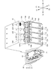
図3は、記録装置10のうちキャリッジ機構50およびインクタンク70を取り付ける取付部材22を示す平面図である。図3に示すように、筐体20の内部には、キャリッジ51を備えるキャリッジ機構50が設けられている。キャリッジ51は、キャリッジモーター52の駆動により、スライドガイド部材53に沿って主走査方向(X方向)に移動することを可能としている。なお、キャリッジ51のうち搬送経路に対向する側には、記録ヘッド54が取り付けられていて、この記録ヘッド54のノズルからインクを噴射して、記録用紙に記録画像を形成することを可能としている。
FIG. 3 is a plan view showing the
また、キャリッジ51には、記録ヘッド54に供給するインクを貯留するためのサブタンク55が設けられている。サブタンク55には、後述するインクタンク70から、インクがチューブ集合体80(図4参照)を介して供給される。ただし、サブタンク55を省略する構成を採用することも可能であり、その場合には、サブタンク55の代わりに、インクタンク70から供給されるインクを受領して記録ヘッド54に供給するインク一時収容部を設けても良い。また、サブタンク55やインク一時収容部を設けずに、チューブ集合体80を介して直接にインクタンク70から記録ヘッド54にインクを供給しても良い。
The
筐体20には、スタッカー60が設けられている。スタッカー20は、筐体20のうち、記録用紙が排出される排出口23側(前側;Y1側)から筐体20の内部の後側(Y2側)に向かって設けられている。このスタッカー60は、記録ヘッド54で記録画像が形成された後に排出される記録用紙(図示省略)を積み重ねて貯留する部分である。なお、記録用紙を良好に貯留するために、スタッカー60には、記録用紙の載置を補助するための引出トレイが収納可能に設けられていても良い。
The
図2に示すように、開閉部材40が筐体20に対して開放される場合、支持部材41によって支持される。支持部材41は、筐体20の孔部分20Aを介して、筐体20の内部に収納可能に設けられている。
As shown in FIG. 2, when the opening / closing
ところで、支持部材41が前側(Y1側)に位置するよりも、支持部材41が後側(Y2側)に位置するときの方が、開閉部材40を開いたときに支持するときに必要となる長さが短くて済む。そのため、支持部材41は、可能な限り後側(Y2側)に位置することが好ましいが、一方で、支持部材41は、キャリッジ51と干渉しない位置に設ける必要がある。そのため、支持部材41が筐体20の内部に収納されると、その支持部材41はキャリッジ51の走査領域よりも前側(Y1側)に位置している。
By the way, the time when the
ただし、支持部材41は、筐体20の前側(Y1側)の外装パネル21よりも十分に後側(Y2側)に位置することが好ましい。具体的には、支持部材41は、パネル装置30よりも後側(Y2側)に位置することが好ましく、インクタンク70のY方向中央よりも後側(Y2側)に位置することが好ましい。
However, it is preferable that the
図2に示すように、支持部材41には、フック部41Aが設けられている。フック部41Aは、孔部分20Aの縁部に引っ掛けられる部分であり、支持部材41の延伸方向に沿って単数または複数(図2では2つ)設けられていて、開閉部材40の開き角度は、フック部41Aの数だけ段階的に調整可能となっている。そして、そのフック部41Aの引っ掛けによって、開閉部材40の開き状態が維持可能となる。このような引っ掛けを可能とするために、フック部41Aは、支持部材41の端面から突出し、その突出の下側には、孔部分20Aの縁部に位置する係止部が存在している。なお、支持部材41は、バネによって付勢されているが、その付勢の向きは、支持部材41の下端側が前側(Y1側)に向かう向きとなっている。
As shown in FIG. 2, the
<インクタンク70およびその取付構造について>
次に、インクタンク70について説明する。図2および図3に示すように、筐体20の内部には、インクタンク70が設けられている。インクタンク70は、インクを貯留する部分であり、このインクタンク70から記録ヘッド54に向けてインクが供給される。インクタンク70は、記録されるインクの種類に応じた数だけ設けられていて、その複数のインクタンク70は、主走査方向(X方向)に並ぶように設けられている。
<
Next, the
なお、図2および図3に示す構成では、ブラック、シアン、マゼンタ、イエローの4種類のインクが、それぞれ別々のインクタンク70に貯留されている。ただし、インクの種類は4種類に限られるものではなく、何種類であっても良いが、その場合にはインクの種類に応じた個数のインクタンク70が設けられる。
2 and 3, four types of inks of black, cyan, magenta, and yellow are stored in
図2および図3に示すように、インクタンク70は、筐体20のうち、スタッカー60と外装パネル21との間の部位に、取付部材22を介して取り付けられている。
As shown in FIGS. 2 and 3, the
図4は、インクタンク70が取り付けられる取付部材22およびチョークバルブ機構90を示す斜視図である。取付部材22は、4つのインクタンク70のセットを覆うように設けられているが、後述する注入口73が露出するように、取付部材22には切欠部22Aが設けられている(図3参照)。なお、取付部材22は、インクタンク70と同様に、2段の段形状をなすように設けられていて、上述した切欠部22Aは、低い段部分(下段部70A)の端面70A1に設けられている。
FIG. 4 is a perspective view showing the
また、図2に示すように、インクタンク70は、筐体20のうちスタッカー60を挟んで支持部材41が設けられる側とは反対側の部位(スタッカー60よりもX1側)に配置されている。図2では、支持部材41は筐体20の左側(X2側)に設けられると共に、インクタンク70は筐体20の右側(X1側)に設けられている。
Further, as shown in FIG. 2, the
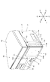
図5は、インクタンク70の構成を示す斜視図である。なお、図5では、インクタンク70のうち、X2側に位置するインクタンク70においては、インクタンク70の内部構成を示すべく、X2側のハウジング70Hの外面部分を取り除いた状態が示されている。インクタンク70は、その内部にインクを貯留するインク貯留室71と、空気室72とを備え、そのインク貯留室71と空気室72とがハウジング70Hによって覆われている。インクタンク70のハウジング70Hは、図5に示す構成では、2段の段形状をなすように設けられている。そのうち、低い段部分(下段部70A)は、筐体20の前側(Y1側)に位置している。
FIG. 5 is a perspective view showing the configuration of the
下段部70Aの上側の端面70A1(開閉部材40側の端面に対応)には、注入口73が設けられている。注入口73は、ボトルB(図2参照)等に貯留されているインクをインク貯留室71に補充(注入)するための部分である。この注入口73は、端面70A1を貫く開口部73Aを有すると共に、この開口部73Aを覆う外周フランジ部73Bを有している。注入口73が開口部73Aのみならず、外周フランジ部73Bを有していることにより、ボトルBを介してのインクの補充が容易に行えるようになっている。なお、外周フランジ部73Bの最も前側(Y1側)の部分は、ハウジング70Hの前側の側面に近接して設けられているが、外周フランジ部73Bの最も前側(Y1側)の部分がハウジング70Hの前側の側面と面一に設けられていても良い。
An
なお、下段部70Aは、段部に対応する。本実施の形態では、下段部70Aは、インクタンク70のうち回動軸から離れる縁部に面して設けられている。また、インクタンク70は3段以上の段形状をなすように設けられていても良い。この場合、上側の端面70A1よりも下方の段部であれば、いずれの段部に注入口73を設けても良い。また、下段部70Aは、インクタンク70の前側(Y1側)の縁部に設けられているが、インクタンク70の前後方向(Y方向)の中央よりも前側(Y1側)であれば、下段部70Aの前後に上側の端面70A1が存在していても良い。
The
図4に示すように、ハウジング70Hの前側(Y1側)の側面には、マーキング74A,74Bが設けられている。マーキング74A,74Bは、インク貯留室71に残存するインク残量を測る目印となる部分である。マーキング74A,74Bには、インク残量の下限を示すマーキング74Aと、インク残量の上限を示すマーキング74Bとが存在する。インク残量がマーキング74Aを下回ると、ユーザーはインクの補充時期が到来したと認識する。また、インク補充時にインク残量がマーキング74Bに到達すると、ユーザーはインクが満量となるまで補充されたことを認識する。ここで、インク残量の下限を示すマーキング74Aは、下限表示に対応する。なお、下限表示に対応するマーキング74Aは、インクタンク70に存在する構成とはせずに、後述するカバー110の透明部材114Aに設けられる構成としても良い。
As shown in FIG. 4,
なお、それぞれのインクタンク70には、それぞれ異なる種類のインクが貯留されている。そのため、誤った種類のインクを、インクタンク70に補充されるのを防ぐような手段が存在することが好ましい。そのため、図4に示すように、取付部材22には、インクタンク70に貯留されるべきインクの種類を示す種別情報22Bが設けられている。
Each
インクタンク70からキャリッジ51のサブタンク55に向けてインクを供給するために、インクタンク70は、図4に示すようなチューブ集合体80の一端側に接続されている。また、チューブ集合体80の中途部分には、チョークバルブ機構90が設けられている。チューブ集合体80は、インクを流通させるための複数のチューブ81を備えていて、そのチューブ81はインクタンク70とサブタンク55とを連結するように延伸している。本実施の形態では、インクはブラック、シアン、マゼンタ、イエローの4種類であるので、チューブ集合体80を構成するチューブ81も4本設けられている。これらの4本のチューブ81の内部においてインクを流通させる内部流路(図示省略)は、互いに別個に設けられている。なお、チューブ81は、流通路に対応する。
In order to supply ink from the
図4に示すチョークバルブ機構90は、チューブ集合体80の複数のチューブ81を押し潰してその内部流路を閉塞させるものである。この閉塞により、インクタンク70からサブタンク55に向かうインクの流れは停止され、記録装置10を持ち運ぶ場合に記録装置10を傾ける等しても、インクがこぼれたり逆流するのが防止される。このチョークバルブ機構90は、インクタンク70とスタッカー60の間に設けられている。このチョークバルブ機構90は、つまみ91を備えていて、そのつまみ91は、図示を省略するカムに連結されている。
The
図6は、チョークバルブ機構90におけるつまみ91の回転位置を示す図であり、(A)は内部流路の開放状態におけるつまみ91の位置を示し、(B)は内部流路の閉塞状態におけるつまみ91の位置を示している。図6(A)に示すつまみ91の回転位置では、チューブ81は開放されていて、インクはチューブ81の内部流路を流通することが可能となっている。その状態からつまみ91を90度回し、図6(B)に示すつまみ91の回転位置とすると、チューブ集合体80を構成する複数のチューブ81は同時に押し潰されて、インクの流通が阻止される。このようなつまみ91の回転によって、チューブ81の内部流路を閉塞したり開放したりすることを可能としている。
6A and 6B are diagrams showing the rotational position of the
<カバー開閉機構100について>
次に、カバー開閉機構100について説明する。図1および図2に示すように、カバー開閉機構100は、カバー110を備え、このカバー110を筐体20に対して開閉させるための機構である。図2に示すように、カバー110は、筐体20の外装パネル21の前側(Y1側)かつ右側(X1側)の隅角部を切り欠いた切欠部分21Aに装着されている。かかるカバー110が開き、さらに開閉部材40を開いた状態が維持される場合には、注入口73を介して、ボトルBからインクタンク70にインクを補充することが可能となる。一方、ボトルBからインクタンク70へインクを補充しない場合には、カバー110を閉じる状態とする。
<About the cover opening /
Next, the cover opening /
図7は、記録装置10のうちカバー110付近の構成を拡大して示す斜視図である。なお、本明細書においては、カバー110は筐体20に含まれないものとしているが、カバー110が筐体20に含まれるものとしても良い。
FIG. 7 is an enlarged perspective view showing the configuration in the vicinity of the
カバー110は、そのカバー110を閉じて上方から見た形状がL字形状をなしている。そのようなL字形状とするために、カバー110は、第1側面部111と第2側面部112とを有していて、それら第1側面部111と第2側面部112の縁部同士が直交する状態で連続している。また、カバー110を閉じた状態では、第1側面部111は主走査方向(X方向)に沿うように延伸していて、第2側面部112は副走査方向(Y方向)に沿うように延伸している。
The
カバー110には、回動軸113が設けられている。回動軸113は、図7に示す構成では、第2側面部112の後側(Y2側)の上下それぞれの縁部から上下方向に突出して設けられている。この回動軸113を支持するために、筐体20の対向部位には不図示の軸穴が設けられ、この軸穴で回動軸113を回動自在に支持している。
The
図7に示すように、カバー110には、透明部材114Aから構成される視認窓114が設けられている。視認窓114は、図7に示すように第1側面部111に設けられ、次のように構成されている。すなわち、第1側面部111のうち非透明の樹脂等を材質とする視認窓114以外の部分(非透明部110Aとする)に矩形の孔部110Bが設けられ、その孔部110Bに透明部材114Aが嵌め込まれて、視認窓114が構成されている。しかしながら、カバー110は、非透明部110Aと透明部材114Aとの2色成形等によって形成されるものであっても良い。
As shown in FIG. 7, the
このように、カバー110が透明部材114Aから構成される視認窓114を備えることにより、ユーザーは、視認窓114を介してインクタンク70のインク残量を視認することが可能となる。
As described above, the
なお、カバー110は、図1、図2および図7に示すタイプには限られない。他のタイプのカバー110としては、図8〜図12に示すものがある。図8に示すタイプのカバー110では、視認窓114が第1側面部111と第2側面部112とに跨って設けられている。すなわち、孔部110Bが第1側面部111と第2側面部112に亘って連続して設けられていて、その連続した孔部110Bに透明部材114Aが存在することで、視認窓114が構成されている。
Note that the
図9に示すタイプのカバー110では、カバー110全体が透明部材114Aから形成されている。このタイプのカバー110では、カバー110全体が視認窓114として機能する。
In the
図10に示すタイプのカバー110では、第1側面部111の非透明部110Aには、矩形の孔部110Bが設けられているものの、その孔部110Bに透明部材114Aが存在しない構成となっている。
In the
また、上述した図7〜図10に示すタイプのカバー110において、回動軸113の取付位置を変更することも可能である。図11は、前倒しタイプのカバー110を示す図である。以下の説明では、図7〜図10に示すカバー110は、必要に応じて横開きタイプのカバー110と称呼して説明する。
Further, in the
図11に示すような前倒しタイプのカバー110では、図示を省略する回動軸(回動軸113と同様の回転軸)は第1側面部111の下側(Z2側)の縁部から、左右方向(X方向)に突出して設けられている。かかる回動軸を支持するために、筐体20の下方側の対向部位には不図示の軸穴が設けられ、この軸穴で回動軸を回動自在に支持している。
In the forward-
なお、図11では、カバー110は、図7に示すタイプの視認窓114を備えているが、その他の図8〜図10に示すタイプのカバー110についても、横倒しタイプから前倒しタイプに変更することは勿論可能である。
In FIG. 11, the
また、上述した図7〜図11に示すタイプのカバー110において、第1側面部111と第2側面部112以外に、図12に示すような防塵側面部116を備える構成を採用することも可能である。防塵側面部116は、カバー110を筐体20に対して閉じたときに、注入口73を覆う部分である。それによって、カバー110を閉じた状態では、注入口73が防塵側面部116で覆われるため、インクの補充を行わない補充時以外のときでも、埃や異物が注入口73に付着するのを防止できる。この防塵側面部116は、第1側面部111と第2側面部112に対して直交する状態で設けられている。なお、防塵側面部116は、第1側面部111の縁部および第2側面部112の縁部と直交する状態で連続して設けられていても良い。
Further, in the
なお、防塵側面部116は、次のような位置に設けられていても良い。すなわち、カバー110を閉じた場合に、防塵側面部116が注入口73に当接するか、または注入口73に当接しなくても、図12に図示したものよりも、注入口73に近接した位置に設けるようにしても良い。このように構成する場合には、注入口73が、より近い位置で防塵側面部116で覆われるため、インクの補充を行わない補充時以外のときに、埃や異物が注入口73に付着するのを一層効果的に防止できる。
In addition, the dust-
また、カバー110に加えて、図13に示すように、筐体20の外装パネル21に視認窓117を設けるようにしても良い。図13は、カバー110の視認窓114に加えて、外装パネル21に視認窓117が設けられている構成を示す図である。視認窓117は、外装パネル21に矩形の視認用孔21Bを設け、その視認用孔21Bに透明部材117Aが嵌め込まれて構成されている。ただし、視認窓117は、視認窓114よりも小面積に設けられていて、上端の高さが視認窓114よりも低く、下端の高さが視認窓114よりも高く設けられている。
Further, in addition to the
このような視認窓117によっても、インクタンク70におけるインク残量を視認することが可能である。しかしながら、上述した小面積の視認窓117では、大容量のインクタンク70を備えている、という点を外観上からアピールする機能を有しており、インクの補充時期が到来したことを視認するための機能を備えていなくても良い。
The remaining amount of ink in the
<インクタンク70にインクを補充する場合の動作について>
以上のような構成の記録装置10において、インクタンク70にインクを補充する場合の動作について、以下に説明する。
<Operation for
The operation when the
先ず、インクの補充に先立って、図2に示すように開閉部材40を開き、支持部材41のフック部41Aが孔部分20Aの縁部に引っ掛けられる状態とする。それによって、開閉部材40の開き状態が維持されるが、このように開閉部材40を開くことにより、ボトルBから注入口73を介してインクタンク70へインクを補充させるのに必要なスペースが確保される。
First, prior to ink replenishment, the opening / closing
また、開閉部材40を開くのに前後して、カバー110を開くようにする。カバー110を開くと、そのカバー110の上端部分が、インクタンク70から遠ざかる。そのため、インク補充時に、ボトルBがカバー110と干渉しない状態となる。
Further, the
以上のように、開閉部材40とカバー110とを開いた後に、ボトルBの尖形状の注ぎ口を、インクタンク70の注入口73に差し込む。その状態で、ボトルBを押す等することにより、インクがインクタンク70のインク貯留室71に充填されていく。そして、所定だけ充填すると、ボトルBの注ぎ口を注入口73から引き抜き、インクの充填を終了する。
As described above, after opening the opening / closing
<効果について>
以上のような構成の記録装置10によると、インクタンク70は、筐体20の内部に配置され、上方側を覆う開閉部材40によって覆われている。そのため、インクタンク70へのインクの補充が行われないときには、開閉部材40を閉じ状態としておくことにより、注入口73付近に埃がたまったり、異物が存在するのが防止可能となる。また、インクタンク70は、筐体20の内部のうち回動軸とは反対側(前側;Y1側)に位置するように配置されている。このため、開閉部材40を開放させる向きに回動させてインクの補充を行う場合、開閉部材40のうち注入口73と対向する部分は、その開き角度を大きく確保することが可能となり、インクの補充を容易に行うことが可能となる。
<About effect>
According to the
さらに、下段部70Aは、インクタンク70のうち回動軸から離れる側(前側;Y1側)に設けられているので、開閉部材40のうち下段部70Aと対向する部分の開き角度を一層大きく確保することが可能となる。加えて、下段部70Aは、開閉部材40側の端面70A1から離れた下方側(Z2側)の位置に存在する。そのため、注入口73は開閉部材40から離れた下方側(Z2側)に位置し、たとえばインクが充填されたボトルBを介してインクを補充する際に、当該ボトルBが開閉部材40に干渉し難くなる。
Furthermore, since the
なお、下段部70Aは、インクタンク70のうち排出口23側(またはパネル装置30側)に設けられているので、インクの補充が行い易くなる。
Since the
また、下段部70Aは、排出口23側(またはパネル装置30側)の筐体20縁部に面して設けられている。このため、注入口73を介してインクを補充する際には、筐体20の縁部側からボトルB等を出し入れすることが可能となり、加えてボトルB等は縁部側よりも外方に突出する状態で位置させることが可能となる。それにより、インクの補充を一層容易に行うことが可能となる。
Further, the
また、本実施の形態では、下段部70Aがインクタンク70のうち回動軸から離れる縁部側(前側(Y1側)の縁部側)に位置している。このため、注入口73を介してインクを補充する際には、前側の縁部側からボトルBを出し入れすることが可能となり、加えてボトルBは前側の縁部側よりも外方に突出する状態で位置させることが可能となる。それにより、インクの補充を一層容易に行うことが可能となる。
In the present embodiment, the
さらに、本実施の形態では、複数のインクタンク70が主走査方向に並んで配置されるため、全てのインクタンク70の注入口73が、開閉部材40の回動軸とは反対側の筐体20の縁部よりの部位(前側(Y1側)の部位)に設けられる。それにより、インクの補充を行う場合の作業性を、一層向上させることが可能となる。
Further, in the present embodiment, since the plurality of
また、本実施の形態では、カバー110が筐体20に対して開閉する構成となっている。このため、インクタンク70へインクを補充する際の作業性を一層向上させることが可能となる。
In the present embodiment, the
さらに、本実施の形態では、第1側面部111と第2側面部112とを有するカバー110は、平面視した場合の外観がL字形状となる。そのため、カバー110を開くことによって、カバー110の第2側面部112が、筐体20の隅角部から遠ざかる。それにより、隅角部に位置するインクタンク70にインクを補充する場合でも、カバー110がインクの補充の邪魔となるのを防止可能となり、インクの補充の作業性を向上させることが可能となる。
Furthermore, in the present embodiment, the
また、本実施の形態では、開閉部材40を開いた際に、その開閉部材40の開き位置が、支持部材41で保持される。しかも、開閉部材40は、支持部材41によって、ボトルBと干渉しない開き位置に保持される。このため、ボトルBを注入口73に連結させて、インクをインクタンク70へ補充する際の作業性を、一層向上させることが可能となる。
In this embodiment, when the opening / closing
なお、本実施の形態では、開閉部材40を開いた際に、その開閉部材40の開き位置が、支持部材41で保持され、インクを注入するためのスペースを形成することが可能となる。それにより、インクタンク70へのインク補充時の作業性を、一層向上させることが可能となる。
In the present embodiment, when the opening / closing
さらに、本実施の形態では、支持部材41は、筐体20のうち、スタッカー60を挟んでインクタンク70が配置される側とは反対側に設けられている。このため、支持部材41を筐体20に収納しても、その支持部材41がインクタンク70と干渉するのを防止可能となる。それにより、支持部材41を設ける部位のレイアウトの自由性が向上する。
Further, in the present embodiment, the
さらに、本実施の形態では、支持部材41は、キャリッジ51が摺動する走査領域には設けられないため、支持部材41がキャリッジ51と干渉しない状態となる。また、支持部材41は、前側(Y1側)の外装パネル21から離間したキャリッジ51寄りに設けられているので、開閉部材40の開き状態を保持するために必要となる支持部材41の長さを短くすることが可能となる。
Further, in the present embodiment, since the
<変形例>
以上、本発明の一実施の形態について述べたが、本発明は、種々変形可能である。以下、それについて述べる。
<Modification>
Although one embodiment of the present invention has been described above, the present invention can be variously modified. This will be described below.
(1)変形例その1
上述の実施の形態においては、インクの種類に応じて複数のインクタンク70を備える場合について説明している。しかしながら、複数種類のインクが1つのインクタンクに収納されている一体型のインクタンクを備えるものとしても良い。この場合には、インクタンクは、複数種類のインクに応じた数のインク貯留室を備え、そのインク貯留室の数に応じた数の注入口を備えるものとなる。このように構成しても、インクタンク70へのインクの注入が行われないときには、開閉部材40およびカバー110を閉じ状態としておくことにより、インクの注入口付近に埃がたまったり、異物が存在するのが防止可能となる。
(1) Modification 1
In the above-described embodiment, the case where a plurality of
(2)変形例その2
また、上述の実施の形態では、複数のインクタンク70は、主走査方向(X方向)に並んで配置されている。しかしながら、複数のインクタンクは、副走査方向(Y方向)や上下方向(Z方向)に並んで配置されても良い。このように構成しても、インクタンク70へのインクの注入が行われないときには、開閉部材40およびカバー110を閉じ状態としておくことにより、インクの注入口付近に埃がたまったり、異物が存在するのが防止可能となる。
(2) Modification 2
In the above-described embodiment, the plurality of
(3)変形例その3
また、上述の実施の形態では、注入口73は、インクタンク70のうち、下段部70Aの上側の端面70A1に設けられている。しかしながら、注入口は、インクタンクの前側(Y1側)の側面に設けられていても良い。このように構成しても、インクタンク70へのインクの注入が行われないときには、開閉部材40およびカバー110を閉じ状態としておくことにより、インクの注入口付近に埃がたまったり、異物が存在するのが防止可能となる。
(3) Modification 3
In the above-described embodiment, the
(4)変形例その4
また、上述の実施の形態では、インクタンク70は、筐体20のうちスタッカー60を挟んで支持部材41が設けられる側とは反対側の部位に配置されている。しかしながら、インクタンクは、筐体20のうちスタッカー60に対して支持部材41と同じ側に設けられる構成を採用しても良い。なお、この場合には、支持部材41がインクタンク70と干渉しない構成を採用することが必要である。
(4) Modification 4
Further, in the above-described embodiment, the
(5)変形例その5
また、上述の実施の形態におけるインクタンク70の概念に、インクカートリッジのような着脱自在とするものを含めるようにしても良い。このようなインクカートリッジであっても、そのインクカートリッジに注入口を備えるものであれば、本実施の形態における発明と同様に、インクの補充の際の作業性を向上可能であるからである。
(5) Modification 5
Further, the concept of the
(6)変形例その6
上述の実施の形態では、カバー110は、上方から見た形状がL字形状をなしている。しかしながら、カバーの形状は、上方から見た場合にL字形状をなすものには限られない。たとえば、カバーは、上方から見た場合に直線状であっても良く、その他種々の形状を採用することが可能である。
(6) Modification 6
In the above-described embodiment, the
(7)変形例その7
上述の実施の形態では、カバー110に関しては、図2のような横開きタイプか、図11のような前倒しタイプのものにつき説明している。しかしながら、カバーは、これらのタイプには限られず、その他のタイプのものとしても良い。その他のタイプのカバーとしては、たとえば、カバーが、主走査方向(X方向)、副走査方向(Y方向)および上下方向(Z方向)のうちの少なくとも1つの方向にスライドするスライドタイプが挙げられる。
(7) Modification 7
In the above-described embodiment, the
10…記録装置、20…筐体、20A…孔部分、21…外装パネル、21A…切欠部分、21B…視認用孔、22…取付部材、22A…切欠部、22B…種別情報、23…排出口、30…パネル装置、40…開閉部材、41…支持部材、41A…フック部、50…キャリッジ機構、51…キャリッジ、52…キャリッジモーター、53…スライドガイド部材、54…記録ヘッド、55…サブタンク、60…スタッカー、70…インクタンク、70A…下段部(段部に対応)、70A1…端面(開閉部材側の端面に対応)、70H…ハウジング、71…インク貯留室、72…空気室、73…注入口、73A…開口部、73B…外周フランジ部、74A…マーキング、74B…マーキング、80…チューブ集合体、81…チューブ(流通路に対応)、90…チョークバルブ機構、100…カバー開閉機構、110…カバー、110A…非透明部、110B…孔部、111…第1側面部、112…第2側面部、113…回動軸、114…視認窓、114A…透明部材、116…防塵側面部、117…視認窓、117A…透明部材、B…ボトル
DESCRIPTION OF
Claims (10)
前記筺体の上面側を覆うと共に、回動軸により軸支される開閉部材と、
前記筺体に対し、前記開閉部材を特定の開き位置で保持する保持部材と、
インクを噴射する記録ヘッドと、
記録に用いられるインクを供給する注入口を有するインクタンクと、
を具備し、
前記インクタンクは、前記回動軸とは反対側の隅角部に位置するように配置されていて、
前記筐体に対して開閉可能であると共に前記インクタンクの少なくとも一部を覆うカバーが設けられ、
前記カバーは、前記カバーが閉じた状態において、前記記録ヘッドが移動する主走査方向に延伸する第1側面と、前記主走査方向に対して交差する前記回動軸方向に延伸する第2側面とを有し、前記第1側面と前記第2側面とによって前記筐体の隅角部に跨って存在すると共に、前記カバーは、前記注入口よりも前記開閉部材側に延伸して設けられている、
ことを特徴とする記録装置。 A housing,
An opening / closing member that covers the upper surface side of the housing and is pivotally supported by a rotation shaft;
A holding member that holds the opening and closing member at a specific opening position with respect to the housing;
A recording head for ejecting ink;
An ink tank having an inlet for supplying ink used for recording;
Comprising
The ink tank is disposed so as to be located at a corner on the opposite side to the rotation shaft,
A cover that can be opened and closed with respect to the housing and covers at least a part of the ink tank;
The cover includes a first side surface extending in a main scanning direction in which the recording head moves in a state where the cover is closed, and a second side surface extending in the rotational axis direction intersecting the main scanning direction. And the first side surface and the second side surface are present across the corner of the housing, and the cover is provided to extend to the opening / closing member side from the injection port. ,
A recording apparatus.
前記筺体の上面側を覆うと共に、回動軸により軸支される開閉部材と、
前記筺体に対し、前記開閉部材を特定の開き位置で保持する保持部材と、
インクを噴射する記録ヘッドと、
記録に用いられるインクを供給する注入口を有するインクタンクと、
前記記録ヘッドによって記録された記録媒体を排出する排出口と、
を具備し、
前記インクタンクは、前記筺体の前記排出口側の隅角部に配置され、
前記筐体に対して開閉可能であると共に前記インクタンクの少なくとも一部を覆うカバーが設けられ、
前記カバーは、前記カバーが閉じた状態において、前記記録ヘッドが移動する主走査方向に延伸する第1側面と、前記主走査方向に対して交差する前記排出口とは反対方向に延伸する第2側面とを有し、前記第1側面と前記第2側面とによって前記筐体の隅角部に跨って存在すると共に、前記カバーは、前記注入口よりも前記開閉部材側に延伸して設けられている、
ことを特徴とする記録装置。 A housing,
An opening / closing member that covers the upper surface side of the housing and is pivotally supported by a rotation shaft;
A holding member that holds the opening and closing member at a specific opening position with respect to the housing;
A recording head for ejecting ink;
An ink tank having an inlet for supplying ink used for recording;
A discharge port for discharging the recording medium recorded by the recording head;
Comprising
The ink tank is arranged at a corner portion on the discharge port side of the casing,
A cover that can be opened and closed with respect to the housing and covers at least a part of the ink tank;
The cover extends in a direction opposite to the first side surface extending in the main scanning direction in which the recording head moves and the discharge port intersecting the main scanning direction when the cover is closed. And the first side surface and the second side surface are present across the corner portion of the housing, and the cover is provided to extend to the opening / closing member side from the injection port. ing,
A recording apparatus.
前記筺体の上面側を覆うと共に、回動軸により軸支される開閉部材と、
前記筺体に対し、前記開閉部材を特定の開き位置で保持する保持部材と、
インクを噴射する記録ヘッドと、
記録に用いられるインクを供給する注入口を有するインクタンクと、
前記インクタンクと前記記録ヘッドとの間で前記インクを流通させる流通路と、
を具備し、
前記インクタンクは、前記記録ヘッドの走査方向に対し、前記保持部材を設けた側とは反対側の隅角部に配置され、
前記筐体に対して開閉可能であると共に前記インクタンクの少なくとも一部を覆うカバーが設けられ、
前記カバーは、前記カバーが閉じた状態において、前記記録ヘッドが移動する主走査方向に延伸する第1側面と、前記主走査方向に対して交差する前記回動軸方向に延伸する第2側面とを有し、前記第1側面と前記第2側面とによって前記筐体の隅角部に跨って存在すると共に、前記カバーは、前記注入口よりも前記開閉部材側に延伸して設けられている、
ことを特徴とする記録装置。 A housing,
An opening / closing member that covers the upper surface side of the housing and is pivotally supported by a rotation shaft;
A holding member that holds the opening and closing member at a specific opening position with respect to the housing;
A recording head for ejecting ink;
An ink tank having an inlet for supplying ink used for recording;
A flow path through which the ink flows between the ink tank and the recording head;
Comprising
The ink tank is arranged at a corner on the opposite side to the side where the holding member is provided with respect to the scanning direction of the recording head,
A cover that can be opened and closed with respect to the housing and covers at least a part of the ink tank;
The cover includes a first side surface extending in a main scanning direction in which the recording head moves in a state where the cover is closed, and a second side surface extending in the rotational axis direction intersecting the main scanning direction. And the first side surface and the second side surface are present across the corner of the housing, and the cover is provided to extend to the opening / closing member side from the injection port. ,
A recording apparatus.
前記筺体の上面側を覆うと共に、回動軸により軸支される開閉部材と、
前記筺体に対し、前記開閉部材を特定の開き位置で保持する保持部材と、
インクを噴射する記録ヘッドと、
記録に用いられるインクを供給する注入口を有するインクタンクと、
前記インクタンクと前記記録ヘッドとの間で前記インクを流通させる流通路と、
各種の操作を行うための操作ボタンを備えるパネル装置と、
を具備し、
前記インクタンクは、前記筺体の前記パネル装置側の隅角部に配置され、
前記筐体に対して開閉可能であると共に前記インクタンクの少なくとも一部を覆うカバーが設けられ、
前記カバーは、前記カバーが閉じた状態において、前記記録ヘッドが移動する主走査方向に延伸する第1側面と、前記主走査方向に対して交差する前記パネル位置とは反対方向に延伸する第2側面とを有し、前記第1側面と前記第2側面とによって前記筐体の隅角部に跨って存在すると共に、前記カバーは、前記注入口よりも前記開閉部材側に延伸して設けられている、
ことを特徴とする記録装置。 A housing,
An opening / closing member that covers the upper surface side of the housing and is pivotally supported by a rotation shaft;
A holding member that holds the opening and closing member at a specific opening position with respect to the housing;
A recording head for ejecting ink;
An ink tank having an inlet for supplying ink used for recording;
A flow path through which the ink flows between the ink tank and the recording head;
A panel device having operation buttons for performing various operations;
Comprising
The ink tank is disposed at a corner portion on the panel device side of the casing,
A cover that can be opened and closed with respect to the housing and covers at least a part of the ink tank;
The cover has a first side surface extending in a main scanning direction in which the recording head moves in a state where the cover is closed, and a second side extending in a direction opposite to the panel position intersecting the main scanning direction. And the first side surface and the second side surface are present across the corner portion of the housing, and the cover is provided to extend to the opening / closing member side from the injection port. ing,
A recording apparatus.
前記注入口は、前記インクタンクの上面より低い位置に形成されていることを特徴とする記録装置。 The recording apparatus according to any one of claims 1 to 4, wherein:
The recording apparatus according to claim 1, wherein the injection port is formed at a position lower than an upper surface of the ink tank.
前記注入口は、前記インクタンクの上面と前記インクタンクの正面との間に形成されることを特徴とする記録装置。 The recording apparatus according to any one of claims 1 to 5, wherein
The recording apparatus according to claim 1, wherein the injection port is formed between an upper surface of the ink tank and a front surface of the ink tank.
複数の前記インクタンクは、前記主走査方向に並んで一体的に配置されている、
ことを特徴とする記録装置。 The recording apparatus according to any one of claims 1 to 6,
The plurality of ink tanks are integrally arranged side by side in the main scanning direction.
A recording apparatus.
前記カバーには、前記インクタンクに残存するインクの量を視認可能とする視認窓が設
けられ、
前記視認窓は、前記第1側面または前記第2側面の少なくとも一方に設けられている、
ことを特徴とする記録装置。 The recording apparatus according to any one of claims 1 to 7,
The cover is provided with a visual recognition window that makes it possible to visually recognize the amount of ink remaining in the ink tank,
The viewing window is provided on at least one of the first side surface or the second side surface,
A recording apparatus.
前記注入口は、前記インクを補充する際には、前記インクを補充するためのボトルが連
結されると共に、
前記ボトルが前記注入口に連結された場合には、前記開閉部材は前記ボトルと干渉しな
い開き位置に前記保持部材によって保持される、
ことを特徴とする記録装置。 The recording apparatus according to any one of claims 1 to 8,
When the ink is replenished with the ink, a bottle for replenishing the ink is connected,
When the bottle is connected to the inlet, the opening and closing member is held by the holding member at an open position that does not interfere with the bottle.
A recording apparatus.
前記インクタンクは、正面側に段差部を有する段形状が設けられ、
前記注入口は、前記段差部に設けられていることを特徴とする記録装置。 The recording apparatus according to any one of claims 1 to 9,
The ink tank is provided with a step shape having a step portion on the front side,
The recording apparatus according to claim 1, wherein the injection port is provided in the stepped portion.
Priority Applications (13)
| Application Number | Priority Date | Filing Date | Title |
|---|---|---|---|
| JP2012227713A JP6083187B2 (en) | 2012-10-15 | 2012-10-15 | Recording device |
| US14/049,086 US9421781B2 (en) | 2012-10-15 | 2013-10-08 | Recording apparatus |
| CN201510308720.9A CN104972766A (en) | 2012-10-15 | 2013-10-15 | Recording apparatus |
| CN201610369635.8A CN105856852B (en) | 2012-10-15 | 2013-10-15 | Tape deck |
| CN201610367951.1A CN106042653B (en) | 2012-10-15 | 2013-10-15 | Tape deck |
| CN201610370746.0A CN106042654A (en) | 2012-10-15 | 2013-10-15 | Recording apparatus |
| CN201610370756.4A CN106004068B (en) | 2012-10-15 | 2013-10-15 | Tape deck |
| CN201310481512.XA CN103722892B (en) | 2012-10-15 | 2013-10-15 | Recording equipment |
| US14/593,881 US9511591B2 (en) | 2012-10-15 | 2015-01-09 | Recording apparatus |
| US14/737,008 US9427972B2 (en) | 2012-10-15 | 2015-06-11 | Recording apparatus |
| US29/537,554 USD836113S1 (en) | 2012-10-15 | 2015-08-27 | Recording apparatus |
| US15/074,888 US9505224B2 (en) | 2012-10-15 | 2016-03-18 | Recording apparatus |
| US29/670,481 USD962941S1 (en) | 2012-10-15 | 2018-11-16 | Recording apparatus |
Applications Claiming Priority (1)
| Application Number | Priority Date | Filing Date | Title |
|---|---|---|---|
| JP2012227713A JP6083187B2 (en) | 2012-10-15 | 2012-10-15 | Recording device |
Related Child Applications (1)
| Application Number | Title | Priority Date | Filing Date |
|---|---|---|---|
| JP2017010066A Division JP6361752B2 (en) | 2017-01-24 | 2017-01-24 | Recording device |
Publications (3)
| Publication Number | Publication Date |
|---|---|
| JP2014079909A JP2014079909A (en) | 2014-05-08 |
| JP2014079909A5 JP2014079909A5 (en) | 2015-11-26 |
| JP6083187B2 true JP6083187B2 (en) | 2017-02-22 |
Family
ID=50784584
Family Applications (1)
| Application Number | Title | Priority Date | Filing Date |
|---|---|---|---|
| JP2012227713A Active JP6083187B2 (en) | 2012-10-15 | 2012-10-15 | Recording device |
Country Status (1)
| Country | Link |
|---|---|
| JP (1) | JP6083187B2 (en) |
Families Citing this family (25)
| Publication number | Priority date | Publication date | Assignee | Title |
|---|---|---|---|---|
| US9421781B2 (en) | 2012-10-15 | 2016-08-23 | Seiko Epson Corporation | Recording apparatus |
| JP6415114B2 (en) | 2014-05-30 | 2018-10-31 | キヤノン株式会社 | Liquid storage unit, liquid discharge apparatus using the same, and method for removing bubbles from liquid storage unit |
| JP6460304B2 (en) * | 2014-06-12 | 2019-01-30 | ブラザー工業株式会社 | Liquid consuming device and multifunction machine |
| JP6387693B2 (en) * | 2014-06-12 | 2018-09-12 | ブラザー工業株式会社 | tank |
| JP6428114B2 (en) | 2014-09-30 | 2018-11-28 | ブラザー工業株式会社 | Liquid consumption device |
| JP6795876B2 (en) | 2014-10-31 | 2020-12-02 | ブラザー工業株式会社 | Liquid consumer |
| JP6358106B2 (en) * | 2015-01-19 | 2018-07-18 | ブラザー工業株式会社 | Liquid consumption device |
| JP6631019B2 (en) * | 2015-03-12 | 2020-01-15 | セイコーエプソン株式会社 | Liquid container unit |
| TWI675758B (en) * | 2015-03-30 | 2019-11-01 | 日商精工愛普生股份有限公司 | Printer |
| TW201641311A (en) * | 2015-03-30 | 2016-12-01 | 精工愛普生股份有限公司 | Printer |
| JP6547943B2 (en) * | 2015-03-30 | 2019-07-24 | セイコーエプソン株式会社 | Printing device |
| JP2017001249A (en) * | 2015-06-09 | 2017-01-05 | セイコーエプソン株式会社 | Liquid injection device |
| CN107635780B (en) | 2015-06-09 | 2019-12-31 | 精工爱普生株式会社 | Liquid ejecting apparatus, tank unit, and printer |
| JP6015817B1 (en) * | 2015-06-26 | 2016-10-26 | セイコーエプソン株式会社 | Printing device |
| JP6657670B2 (en) * | 2015-08-26 | 2020-03-04 | セイコーエプソン株式会社 | Recording device |
| CN111845094B (en) | 2016-06-10 | 2022-01-11 | 精工爱普生株式会社 | Ink replenishing container |
| US10350901B2 (en) | 2016-06-10 | 2019-07-16 | Seiko Epson Corporation | Ink bottle |
| US10308029B2 (en) | 2016-06-10 | 2019-06-04 | Seiko Epson Corporation | Liquid holding unit and liquid ejection device |
| TWI774588B (en) | 2016-06-10 | 2022-08-11 | 日商精工愛普生股份有限公司 | ink supply container |
| CN107487083B (en) | 2016-06-10 | 2020-09-22 | 精工爱普生株式会社 | Ink replenishing container |
| EP3663092B1 (en) | 2016-06-10 | 2022-08-24 | Seiko Epson Corporation | Use of an ink refill container |
| CN207291315U (en) | 2016-06-10 | 2018-05-01 | 精工爱普生株式会社 | Ink replenishing container and ink replenishing system |
| JP6705361B2 (en) * | 2016-06-10 | 2020-06-03 | セイコーエプソン株式会社 | Ink supply container |
| JP2018144239A (en) | 2017-03-01 | 2018-09-20 | セイコーエプソン株式会社 | Printer and ink bottle |
| JP6743250B2 (en) * | 2019-07-10 | 2020-08-19 | キヤノン株式会社 | Inkjet recording device |
Family Cites Families (12)
| Publication number | Priority date | Publication date | Assignee | Title |
|---|---|---|---|---|
| JP2003103801A (en) * | 2001-09-28 | 2003-04-09 | Canon Inc | Ink jet recorder |
| JP4595425B2 (en) * | 2004-07-28 | 2010-12-08 | ブラザー工業株式会社 | Recording device |
| JP4386173B2 (en) * | 2003-12-26 | 2009-12-16 | ブラザー工業株式会社 | Image forming apparatus |
| JP2007030195A (en) * | 2005-07-22 | 2007-02-08 | Canon Inc | Ink jet recorder |
| JP2007106019A (en) * | 2005-10-14 | 2007-04-26 | Seiko Epson Corp | Inkjet recording device |
| JP4525620B2 (en) * | 2006-03-07 | 2010-08-18 | ブラザー工業株式会社 | Image recording device, multi-function device |
| JP4941110B2 (en) * | 2007-06-01 | 2012-05-30 | ブラザー工業株式会社 | Inkjet printer |
| JP5066017B2 (en) * | 2008-07-02 | 2012-11-07 | 株式会社リコー | Image forming apparatus |
| JP5691307B2 (en) * | 2010-09-03 | 2015-04-01 | セイコーエプソン株式会社 | Liquid container and liquid ejection system |
| JP5633257B2 (en) * | 2010-09-03 | 2014-12-03 | セイコーエプソン株式会社 | Liquid supply system and liquid consumption apparatus including liquid supply system |
| JP5760399B2 (en) * | 2010-11-16 | 2015-08-12 | セイコーエプソン株式会社 | Liquid refill container |
| JP5787055B2 (en) * | 2011-02-28 | 2015-09-30 | セイコーエプソン株式会社 | Recording device |
-
2012
- 2012-10-15 JP JP2012227713A patent/JP6083187B2/en active Active
Also Published As
| Publication number | Publication date |
|---|---|
| JP2014079909A (en) | 2014-05-08 |
Similar Documents
| Publication | Publication Date | Title |
|---|---|---|
| JP6083187B2 (en) | Recording device | |
| JP6083186B2 (en) | Recording device | |
| US9505224B2 (en) | Recording apparatus | |
| US10286676B2 (en) | Recording apparatus | |
| JP2014079910A (en) | Recording device | |
| JP5633257B2 (en) | Liquid supply system and liquid consumption apparatus including liquid supply system | |
| JP6852394B2 (en) | Liquid injection device | |
| JP5866856B2 (en) | Liquid supply system and liquid consumption apparatus including liquid supply system | |
| JP2015163462A (en) | Liquid supply device, liquid ejection device, and liquid container unit | |
| JP6361752B2 (en) | Recording device | |
| CN103722891B (en) | Tape deck | |
| JP2018089852A (en) | Liquid storage unit and liquid jet device | |
| JP2009184283A (en) | Liquid container and liquid consuming device | |
| JP6748617B2 (en) | Ink tank and inkjet recording device | |
| WO2007117036A1 (en) | Liquid container | |
| JP6347202B2 (en) | Liquid consumption device | |
| JP2019115999A (en) | Liquid jet device | |
| JP2019202464A (en) | Ink tank unit, printer | |
| JP5928692B2 (en) | Recording device | |
| JP6003959B2 (en) | Ink supply system and inkjet printer | |
| JP2015112777A (en) | Recording device | |
| JP2017104993A (en) | Liquid supply unit and recording device | |
| JP2017035859A (en) | Compound machine |
Legal Events
| Date | Code | Title | Description |
|---|---|---|---|
| RD04 | Notification of resignation of power of attorney |
Free format text: JAPANESE INTERMEDIATE CODE: A7424 Effective date: 20150108 |
|
| A521 | Written amendment |
Free format text: JAPANESE INTERMEDIATE CODE: A523 Effective date: 20151006 |
|
| A621 | Written request for application examination |
Free format text: JAPANESE INTERMEDIATE CODE: A621 Effective date: 20151006 |
|
| RD04 | Notification of resignation of power of attorney |
Free format text: JAPANESE INTERMEDIATE CODE: A7424 Effective date: 20160610 |
|
| RD03 | Notification of appointment of power of attorney |
Free format text: JAPANESE INTERMEDIATE CODE: A7423 Effective date: 20160624 |
|
| A977 | Report on retrieval |
Free format text: JAPANESE INTERMEDIATE CODE: A971007 Effective date: 20160629 |
|
| A131 | Notification of reasons for refusal |
Free format text: JAPANESE INTERMEDIATE CODE: A131 Effective date: 20160705 |
|
| A521 | Written amendment |
Free format text: JAPANESE INTERMEDIATE CODE: A523 Effective date: 20160728 |
|
| A131 | Notification of reasons for refusal |
Free format text: JAPANESE INTERMEDIATE CODE: A131 Effective date: 20161004 |
|
| A521 | Written amendment |
Free format text: JAPANESE INTERMEDIATE CODE: A523 Effective date: 20161125 |
|
| TRDD | Decision of grant or rejection written | ||
| A01 | Written decision to grant a patent or to grant a registration (utility model) |
Free format text: JAPANESE INTERMEDIATE CODE: A01 Effective date: 20161227 |
|
| A61 | First payment of annual fees (during grant procedure) |
Free format text: JAPANESE INTERMEDIATE CODE: A61 Effective date: 20170109 |
|
| R150 | Certificate of patent or registration of utility model |
Ref document number: 6083187 Country of ref document: JP Free format text: JAPANESE INTERMEDIATE CODE: R150 |