JP2014079910A - Recording device - Google Patents
Recording device Download PDFInfo
- Publication number
- JP2014079910A JP2014079910A JP2012227714A JP2012227714A JP2014079910A JP 2014079910 A JP2014079910 A JP 2014079910A JP 2012227714 A JP2012227714 A JP 2012227714A JP 2012227714 A JP2012227714 A JP 2012227714A JP 2014079910 A JP2014079910 A JP 2014079910A
- Authority
- JP
- Japan
- Prior art keywords
- ink
- housing
- cover
- ink tank
- choke valve
- Prior art date
- Legal status (The legal status is an assumption and is not a legal conclusion. Google has not performed a legal analysis and makes no representation as to the accuracy of the status listed.)
- Withdrawn
Links
Images


Abstract
Description
本発明は、記録装置に関する。 The present invention relates to a recording apparatus.
インクジェットプリンター等の記録装置の中には、たとえば特許文献1に示すものがある。特許文献1に示す記録装置では、インク供給管を閉塞することが可能なバルブがプリンタ外囲器に搭載されている。 Among recording apparatuses such as an ink jet printer, there is one disclosed in Patent Document 1, for example. In the recording apparatus shown in Patent Document 1, a valve capable of closing the ink supply pipe is mounted on the printer envelope.
しかしながら、特許文献1に開示の記録装置では、バルブがプリンタ外囲器に搭載されているため、バルブの開閉の操作を行い難い、という不具合がある。 However, the recording apparatus disclosed in Patent Document 1 has a problem that it is difficult to open and close the valve because the valve is mounted on the printer envelope.
本発明は上記の事情にもとづきなされたもので、その目的とするところは、チョークバルブの開閉を容易に行うことが可能な記録装置を提供しよう、とするものである。 The present invention has been made based on the above circumstances, and an object thereof is to provide a recording apparatus capable of easily opening and closing a choke valve.
上記課題を解決するために、本発明の記録装置は、筐体と、筐体内部に配置され、記録に用いられるインクを充填するインク貯留室を備え、このインク貯留室内部にインクを補充するための注入口とを備えるインクタンクと、インクタンクから供給されるインクを噴射する記録ヘッドと、インクタンクと記録ヘッドとの間でインクを流通させる流通路と、記録ヘッドによって記録された記録媒体を排出する排出口と、筐体の内部に設けられると共に、流通路におけるインクの流通が許容される開状態と、インクの流通が妨げられる閉じ状態とを切り替えることが可能なチョークバルブと、を具備し、チョークバルブは、排出口側であって、インクタンクの側方に配置されている、ものである。 In order to solve the above-described problems, a recording apparatus of the present invention includes a housing and an ink storage chamber that is disposed inside the housing and is filled with ink used for recording. The ink storage chamber is replenished with ink. An ink tank having an inlet for recording, a recording head for ejecting ink supplied from the ink tank, a flow path for distributing ink between the ink tank and the recording head, and a recording medium recorded by the recording head And a choke valve provided inside the housing and capable of switching between an open state in which the ink flow is allowed in the flow passage and a closed state in which the ink flow is blocked. The choke valve is disposed on the discharge port side and on the side of the ink tank.
このように構成する場合には、チョークバルブは、排出口側に存在し、かつインクタンクの側方に存在している。このため、ユーザーは、チョークバルブの存在を容易に認識することが可能となると共に、チョークバルブの操作性を向上させることが可能となる。 In such a configuration, the choke valve exists on the discharge port side and on the side of the ink tank. For this reason, the user can easily recognize the presence of the choke valve and can improve the operability of the choke valve.
また、他の本発明の記録装置は、筐体と、筐体内部に配置され、記録に用いられるインクを充填するインク貯留室を備え、このインク貯留室内部にインクを補充するための注入口とを備えるインクタンクと、インクタンクから供給されるインクを噴射する記録ヘッドと、インクタンクと記録ヘッドとの間でインクを流通させる流通路と、各種の操作を行うための操作ボタンを備えるパネル装置と、筐体の内部に設けられると共に、流通路におけるインクの流通が許容される開状態と、インクの流通が妨げられる閉じ状態とを切り替えることが可能なチョークバルブと、を具備し、チョークバルブは、パネル装置側であって、インクタンクの側方に配置されている、ものである。 Another recording apparatus of the present invention includes a casing and an ink storage chamber that is disposed inside the casing and is filled with ink used for recording, and an inlet for replenishing the ink in the ink storage chamber A panel having an ink tank, a recording head for ejecting ink supplied from the ink tank, a flow path for distributing ink between the ink tank and the recording head, and operation buttons for performing various operations A choke valve provided inside the housing and capable of switching between an open state in which the flow of ink in the flow passage is allowed and a closed state in which the flow of ink is hindered. The valve is disposed on the panel device side and on the side of the ink tank.
このように構成する場合には、チョークバルブは、パネル装置側に存在し、かつインクタンクの側方に存在している。このため、ユーザーは、チョークバルブの存在を容易に認識することが可能となると共に、チョークバルブの操作性を向上させることが可能となる。 In such a configuration, the choke valve is present on the panel device side and on the side of the ink tank. For this reason, the user can easily recognize the presence of the choke valve and can improve the operability of the choke valve.
また、本発明の他の側面は、上述の発明において、筐体には、記録ヘッドによって記録された記録媒体を蓄えると共に当該蓄える記録媒体のうち最大のものに対応したサイズに形成されるスタッカーを備えると共に、インクタンクは、筐体の隅角部側に配置されていて、チョークバルブは、インクタンクとスタッカーとの間に配置されている、ことが好ましい。 In addition, according to another aspect of the present invention, in the above-described invention, the housing stores a recording medium recorded by the recording head, and a stacker formed in a size corresponding to the largest one of the stored recording media. Preferably, the ink tank is disposed on the corner portion side of the housing, and the choke valve is disposed between the ink tank and the stacker.
このように構成する場合には、インクタンクとスタッカーの間の部位にチョークバルブを配置することが可能となる。ここで、記録媒体を蓄えるスタッカーは、記録媒体に応じたサイズに形成されるため、筐体の隅角部側に配置されるインクタンクとの間はデッドスペースとなることが多いが、本発明では、そのようなデッドスペースを有効に活用することが可能となる。かかるデッドスペースの有効活用により、記録装置が大型化するのを防ぐことが可能となる。 In the case of such a configuration, a choke valve can be disposed at a portion between the ink tank and the stacker. Here, since the stacker for storing the recording medium is formed in a size corresponding to the recording medium, there is often a dead space between the ink tank arranged on the corner side of the casing. Then, it becomes possible to effectively use such dead space. By effectively utilizing such dead space, it is possible to prevent the recording apparatus from becoming large.
さらに、本発明の他の側面は、上述の発明において、チョークバルブは、開状態と閉じ状態とを切り替える際に回転させられる回転レバーを備えると共に、回転レバーは、筐体の外部に露出して設けられている、ことが好ましい。 Further, according to another aspect of the present invention, in the above-described invention, the choke valve includes a rotation lever that is rotated when switching between an open state and a closed state, and the rotation lever is exposed to the outside of the housing. It is preferable that it is provided.
このように構成する場合には、回転レバーが筐体の前側の外部に露出した状態となる。そのため、ユーザーは、チョークバルブの存在を容易に認識することが可能となると共に、チョークバルブの操作性を一層向上させることが可能となる。 In such a configuration, the rotating lever is exposed to the outside on the front side of the housing. Therefore, the user can easily recognize the presence of the choke valve and can further improve the operability of the choke valve.
また、本発明の他の側面は、上述の発明において、チョークバルブは、カバー体を備え、カバー体は、第1カバーと第2カバーとの間の取り付けによって構成されると共に、第1カバーと前記第2カバーのうちの少なくとも一方は、流通路の一部であるバルブ内流通路を覆う状態で筐体を構成するベース体と一体的に形成されている、ことが好ましい。 According to another aspect of the present invention, in the above-described invention, the choke valve includes a cover body, and the cover body is configured by attachment between the first cover and the second cover, It is preferable that at least one of the second covers is formed integrally with a base body that constitutes the housing in a state of covering the in-valve flow passage that is a part of the flow passage.
このように構成する場合には、第1カバーと第2カバーのうちの少なくとも一方がベース体と一体的に設けられるため、部品点数を削減することが可能となる。それにより、取付工数を削減することが可能となり、コストを低減することが可能となる。 In such a configuration, at least one of the first cover and the second cover is provided integrally with the base body, so that the number of parts can be reduced. Thereby, it becomes possible to reduce an installation man-hour and to reduce cost.
また、本発明の他の側面は、上述の発明において、筐体の前側には、各種の操作を行うための操作ボタンを備えるパネル装置が設けられていて、チョークバルブは、記録ヘッドが走査する主走査方向においてパネル装置と重なる部位に設けられている、ことが好ましい。 According to another aspect of the present invention, in the above-described invention, a panel device having operation buttons for performing various operations is provided on the front side of the housing, and the choke valve is scanned by the recording head. It is preferable to be provided in a portion overlapping with the panel device in the main scanning direction.
このように構成する場合には、チョークバルブは、記録ヘッドが走査する主走査方向においてパネル装置と重なる部位に設けられているため、チョークバルブの操作性を向上させることが可能となる。すなわち、パネル装置やチョークバルブといった操作系が、ある範囲内に配置されるレイアウトとなる。そのため、ユーザーにとっては、チョークバルブが他の部位に存在する場合よりも、チョークバルブの操作性を向上させることが可能となる。 In the case of such a configuration, the choke valve is provided in a portion overlapping the panel device in the main scanning direction scanned by the recording head, so that the operability of the choke valve can be improved. That is, the layout is such that operation systems such as panel devices and choke valves are arranged within a certain range. Therefore, it is possible for the user to improve the operability of the choke valve as compared with the case where the choke valve is present in another part.
以下、本発明の一実施の形態に係る記録装置10について、図面を参照しながら説明する。なお、以下の各図面においては、必要に応じて、方向を特定するために互いに直交するXYZ軸が図示されており、この他の図においても必要に応じてXYZ軸が図示されている。この中で、図1等に示す矢示X1方向を「右」、矢示X2方向を「左」、X方向に直交する方向であり記録用紙(記録媒体の一種)が排出される方向である矢示Y1方向を「前」、矢示Y2方向を「後ろ」、XY平面と直交する矢示Z1方向を「上」および矢示Z2方向を「下」とそれぞれ規定する。
Hereinafter, a
<記録装置10の構成について>
図1は、本発明の一実施形態に係る記録装置10の斜視図であり、開閉部材40を閉じた状態を示している。また、図2は、開閉部材40を開いた状態の記録装置10の斜視図である。
<Regarding Configuration of
FIG. 1 is a perspective view of a
図1および図2に示すように、記録装置10には、外装パネル21を備える筐体20が設けられている。外装パネル21は、筐体20の外装部分に設けられている。なお、図2に示すように、外装パネル21の前側(Y1側)の隅角部(図2では右側(X1側)の隅角部)は切り欠かれた切欠部分21Aとなっていて、この切欠部分21Aには、後述するカバー110が装着される。また、筐体20には、パネル装置30が取り付けられている。パネル装置30は、不図示の回動軸を支点として、筐体20に回動可能に設けられている。ただし、パネル装置30は、筐体20に対して回動しない構成を採用しても良い。
As shown in FIGS. 1 and 2, the
図2に示すように、開閉部材40は、図示を省略する回動軸を介して、筐体20に対して開閉可能に取り付けられている。回動軸は、筐体20の後方側(Y2側)に設けられている。図2に示す構成では、開閉部材40は、たとえば原稿を読み取る機能を有するスキャナーユニットとなっている。しかしながら、開閉部材40はスキャナーユニットに限られるものではなく、蓋部材や、その他の部材であっても良い。開閉部材40は、筐体20の上方の端面(一方の端面)を覆うように設けられている。
As shown in FIG. 2, the opening /
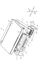
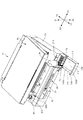
図3は、記録装置10のうちキャリッジ機構50およびインクタンク70を取り付ける取付部材22を示す平面図である。図3に示すように、筐体20の下方側には、その筐体20の一部となるベース体20Bが設けられている。筐体20の内部には、キャリッジ51を備えるキャリッジ機構50が設けられている。キャリッジ51は、キャリッジモーター52の駆動により、スライドガイド部材53に沿って主走査方向(X方向)に移動することを可能としている。なお、キャリッジ51のうち搬送経路に対向する側には、記録ヘッド54が取り付けられていて、この記録ヘッド54のノズルからインクを噴射して、記録用紙に記録画像を形成することを可能としている。
FIG. 3 is a plan view showing the
また、キャリッジ51には、記録ヘッド54に供給するインクを貯留するためのサブタンク55が設けられている。サブタンク55には、後述するインクタンク70から、インクがチューブ集合体80(図4参照)を介して供給される。ただし、サブタンク55を省略する構成を採用することも可能であり、その場合には、サブタンク55の代わりに、インクタンク70から供給されるインクを受領して記録ヘッド54に供給するインク一時収容部を設けても良い。また、サブタンク55やインク一時収容部を設けずに、チューブ集合体80を介して直接にインクタンク70から記録ヘッド54にインクを供給しても良い。
The
筐体20には、スタッカー60が設けられている。スタッカー20は、筐体20のうち、記録用紙が排出される排出口23側(前側;Y1側)から筐体20の内部の後側(Y2側)に向かって設けられている。このスタッカー60は、記録ヘッド54で記録画像が形成された後に排出される記録用紙(図示省略)を積み重ねて貯留する部分である。なお、記録用紙を良好に貯留するために、スタッカー60には、記録用紙の載置を補助するための引出トレイが収納可能に設けられていても良い。
The
図2に示すように、開閉部材40が筐体20に対して開放される場合、支持部材41によって支持される。支持部材41は、筐体20の孔部分20Aを介して、筐体20の内部に収納可能に設けられている。
As shown in FIG. 2, when the opening / closing
ところで、支持部材41が前側(Y1側)に位置するよりも、支持部材41が後側(Y2側)に位置するときの方が、開閉部材40を開いたときに支持するときに必要となる長さが短くて済む。そのため、支持部材41は、可能な限り後側(Y2側)に位置することが好ましいが、一方で、支持部材41は、キャリッジ51と干渉しない位置に設ける必要がある。そのため、支持部材41が筐体20の内部に収納されると、その支持部材41はキャリッジ51の走査領域よりも前側(Y1側)に位置している。
By the way, the time when the
ただし、支持部材41は、筐体20の前側(Y1側)の外装パネル21よりも十分に後側(Y2側)に位置することが好ましい。具体的には、支持部材41は、パネル装置30よりも後側(Y2側)に位置することが好ましく、インクタンク70のY方向中央よりも後側(Y2側)に位置することが好ましい。
However, it is preferable that the
図2に示すように、支持部材41には、フック部41Aが設けられている。フック部41Aは、孔部分20Aの縁部に引っ掛けられる部分であり、支持部材41の延伸方向に沿って単数または複数(図2では2つ)設けられていて、開閉部材40の開き角度は、フック部41Aの数だけ段階的に調整可能となっている。そして、そのフック部41Aの引っ掛けによって、開閉部材40の開き状態が維持可能となる。このような引っ掛けを可能とするために、フック部41Aは、支持部材41の端面から突出し、その突出の下側には、孔部分20Aの縁部に位置する係止部が存在している。なお、支持部材41は、バネによって付勢されているが、その付勢の向きは、支持部材41の下端側が前側(Y1側)に向かう向きとなっている。
As shown in FIG. 2, the
<インクタンク70およびその取付構造について>
次に、インクタンク70について説明する。図2および図3に示すように、筐体20の内部には、インクタンク70が設けられている。インクタンク70は、インクを貯留する部分であり、このインクタンク70から記録ヘッド54に向けてインクが供給される。インクタンク70は、記録されるインクの種類に応じた数だけ設けられていて、その複数のインクタンク70は、主走査方向(X方向)に並ぶように設けられている。
<
Next, the
なお、図2および図3に示す構成では、ブラック、シアン、マゼンタ、イエローの4種類のインクが、それぞれ別々のインクタンク70に貯留されている。ただし、インクの種類は4種類に限られるものではなく、何種類であっても良いが、その場合にはインクの種類に応じた個数のインクタンク70が設けられる。
2 and 3, four types of inks of black, cyan, magenta, and yellow are stored in
図2および図3に示すように、インクタンク70は、筐体20のうち、スタッカー60と外装パネル21との間の部位に、取付部材22を介して取り付けられている。
As shown in FIGS. 2 and 3, the
図4は、インクタンク70が取り付けられる取付部材22およびチョークバルブ90を示す斜視図である。取付部材22は、4つのインクタンク70のセットを覆うように設けられているが、後述する注入口73が露出するように、取付部材22には切欠部22Aが設けられている(図3参照)。なお、取付部材22は、インクタンク70と同様に、2段の段形状をなすように設けられていて、上述した切欠部22Aは、低い段部分(下段部70A)の端面70A1に設けられている。
FIG. 4 is a perspective view showing the
また、図2に示すように、インクタンク70は、筐体20のうちスタッカー60を挟んで支持部材41が設けられる側とは反対側の部位(スタッカー60よりもX1側)に配置されている。図2では、支持部材41は筐体20の左側(X2側)に設けられると共に、インクタンク70は筐体20の右側(X1側)に設けられている。
Further, as shown in FIG. 2, the
図5は、インクタンク70の構成を示す斜視図である。なお、図5では、インクタンク70のうち、X2側に位置するインクタンク70においては、インクタンク70の内部構成を示すべく、X2側のハウジング70Hの外面部分を取り除いた状態が示されている。インクタンク70は、その内部にインクを貯留するインク貯留室71と、空気室72とを備え、そのインク貯留室71と空気室72とがハウジング70Hによって覆われている。インクタンク70のハウジング70Hは、図5に示す構成では、2段の段形状をなすように設けられている。そのうち、低い段部分(下段部70A)は、筐体20の前側(Y1側)に位置している。
FIG. 5 is a perspective view showing the configuration of the
下段部70Aの上側の端面70A1(開閉部材40側の端面に対応)には、注入口73が設けられている。注入口73は、ボトルB(図2参照)等に貯留されているインクをインク貯留室71に補充(注入)するための部分である。この注入口73は、端面70A1を貫く開口部73Aを有すると共に、この開口部73Aを覆う外周フランジ部73Bを有している。注入口73が開口部73Aのみならず、外周フランジ部73Bを有していることにより、ボトルBを介してのインクの補充が容易に行えるようになっている。なお、外周フランジ部73Bの最も前側(Y1側)の部分は、ハウジング70Hの前側の側面に近接して設けられているが、外周フランジ部73Bの最も前側(Y1側)の部分がハウジング70Hの前側の側面と面一に設けられていても良い。
An
なお、下段部70Aは、段部に対応する。本実施の形態では、下段部70Aは、インクタンク70のうち回動軸から離れる縁部に面して設けられている。また、インクタンク70は3段以上の段形状をなすように設けられていても良い。この場合、上側の端面70A1よりも下方の段部であれば、いずれの段部に注入口73を設けても良い。また、下段部70Aは、インクタンク70の前側(Y1側)の縁部に設けられているが、インクタンク70の前後方向(Y方向)の中央よりも前側(Y1側)であれば、下段部70Aの前後に上側の端面70A1が存在していても良い。
The
図4に示すように、ハウジング70Hの前側(Y1側)の側面には、マーキング74A,74Bが設けられている。マーキング74A,74Bは、インク貯留室71に残存するインク残量を測る目印となる部分である。マーキング74A,74Bには、インク残量の下限を示すマーキング74Aと、インク残量の上限を示すマーキング74Bとが存在する。インク残量がマーキング74Aを下回ると、ユーザーはインクの補充時期が到来したと認識する。また、インク補充時にインク残量がマーキング74Bに到達すると、ユーザーはインクが満量となるまで補充されたことを認識する。ここで、インク残量の下限を示すマーキング74Aは、下限表示に対応する。なお、下限表示に対応するマーキング74Aは、インクタンク70に存在する構成とはせずに、後述するカバー110の透明部材114Aに設けられる構成としても良い。
As shown in FIG. 4,
なお、それぞれのインクタンク70には、それぞれ異なる種類のインクが貯留されている。そのため、誤った種類のインクを、インクタンク70に補充されるのを防ぐような手段が存在することが好ましい。そのため、図4に示すように、取付部材22には、インクタンク70に貯留されるべきインクの種類を示す種別情報22Bが設けられている。
Each
インクタンク70からキャリッジ51のサブタンク55に向けてインクを供給するために、インクタンク70は、図4に示すようなチューブ集合体80の一端側に接続されている。また、チューブ集合体80の中途部分には、チョークバルブ90が設けられている。チューブ集合体80は、インクを流通させるための複数のチューブ81を備えていて、そのチューブ81はインクタンク70とサブタンク55とを連結するように延伸している。本実施の形態では、インクはブラック、シアン、マゼンタ、イエローの4種類であるので、チューブ集合体80を構成するチューブ81も4本設けられている。これらの4本のチューブ81の内部においてインクを流通させる内部流路(図示省略)は、互いに別個に設けられている。なお、チューブ81は、流通路に対応する。
In order to supply ink from the
<チョークバルブ90について>
図4に示すチョークバルブ90は、チューブ集合体80の複数のチューブ81を押し潰してその内部流路を閉塞させるものである。この閉塞により、インクタンク70からサブタンク55に向かうインクの流れは停止され、記録装置10を持ち運ぶ場合に記録装置10を傾ける等しても、インクがこぼれたり逆流するのが防止される。このチョークバルブ90は、筐体20の前側(Y1側)に配置されると共に、インクタンク70とスタッカー60の間に設けられている。このチョークバルブ90は、回転レバー91を備えていて、その回転レバー91は、図示を省略するカムに連結されている。回転レバー91は、筐体20の前側(Y1側)において外部に露出している。
<About the
The
なお、図1、図2および図7に示すように、チョークバルブ90は、主走査方向(X方向)においてパネル装置30と重なる部位に設けられている。特に、チョークバルブ90は、その右側端部(X1側の端部)が、パネル装置30の右側端部(X1側の端部)と同程度の位置となるレイアウトを採用している。このレイアウトは、パネル装置30やチョークバルブ90といった操作系の操作性を向上させるために、ある範囲内に配置されるように、構成したものである。
As shown in FIGS. 1, 2, and 7, the
図4に示すように、チョークバルブ90は、カバー体92によってその全体が覆われている。本実施の形態では、カバー体92は、第1カバー92aと第2カバー92bとを備えている。第1カバー92aと第2カバー92bとは別パーツとなるように(別体的に)設けられていて、かかる別体的な第1カバー92aと第2カバー92bとをネジや接着等の手段によって、互いに固定されている。また、本実施の形態では、第1カバー92aは、ベース体20Bと一体的に設けられている。すなわち、第1カバー92aは、ベース体20Bとは別パーツではなく1つのパーツとなるように一体的に設けられている。しかしながら、第1カバー92aではなく、第2カバー92bが、ベース体20Bと一体的に設ける構成を採用しても良い。なお、ベース体20Bは、少なくともその一部が樹脂によって形成されるのが好ましく、その場合には、第1カバー92aと第2カバー92bのうちの一方を、樹脂成形によって一体的に形成することが可能となる。
As shown in FIG. 4, the
図6は、カム93とスライダー94の構成を示す斜視図である。チョークバルブ90のカバー体92の内部には、図6に示すようなカム93と、スライダー94とが設けられている。カム93は、その大部分はカバー体92で覆われた内部に存在している。しかし、カム93の前側(Y1側)の端部がカバー体92から突出し、その端部に回転レバー91が取り付けられている。
FIG. 6 is a perspective view showing the configuration of the
スライダー94は、カバー体92の内部に収容されている。スライダー94は、カム93の回転動作に連動して変位し、スライダー94がカム93から離れるように変位すると、チューブ81のうちカバー体92の内部を通る部位(この部分は、バルブ内流通路に対応)を押し潰す。逆に、スライダー94がカム93側に変位すると、チューブ81のうちカバー体92の内部を通る部位が押し潰されずに開放状態となる。
The
なお、チューブ81のうち、チョークバルブ90のカバー体92の内部を通る部位(バルブ内流通路に対応)は、インクタンク70の内部に貯留されるインクの下限の液面よりも低い位置に設けられている。それにより、チューブ81におけるインクの流通は阻害されない状態となっている。
A portion of the
図7は、チョークバルブ90における回転レバー91の回転位置を示す図であり、(A)は内部流路の開放状態における回転レバー91の位置を示し、(B)は内部流路の閉塞状態における回転レバー91の位置を示している。図7(A)に示す回転レバー91の回転位置では、チューブ81は開放されていて、インクはチューブ81の内部流路を流通することが可能となっている。その状態から回転レバー91を90度回し、図7(B)に示す回転レバー91の回転位置とすると、チューブ集合体80を構成する複数のチューブ81は同時に押し潰されて、インクの流通が阻止される。このような回転レバー91の回転によって、チューブ81の内部流路を閉塞したり開放したりすることを可能としている。
7A and 7B are diagrams showing the rotation position of the
<カバー開閉機構100について>
次に、カバー開閉機構100について説明する。図1および図2に示すように、カバー開閉機構100は、カバー110を備え、このカバー110を筐体20に対して開閉させるための機構である。図2に示すように、カバー110は、筐体20の外装パネル21の前側(Y1側)かつ右側(X1側)の隅角部を切り欠いた切欠部分21Aに装着されている。かかるカバー110が開き、さらに開閉部材40を開いた状態が維持される場合には、注入口73を介して、ボトルBからインクタンク70にインクを補充することが可能となる。一方、ボトルBからインクタンク70へインクを補充しない場合には、カバー110を閉じる状態とする。
<About the cover opening /
Next, the cover opening /
図8は、記録装置10のうちカバー110付近の構成を拡大して示す斜視図である。なお、本明細書においては、カバー110は筐体20に含まれないものとしているが、カバー110が筐体20に含まれるものとしても良い。
FIG. 8 is an enlarged perspective view showing the configuration in the vicinity of the
カバー110は、そのカバー110を閉じて上方から見た形状がL字形状をなしている。そのようなL字形状とするために、カバー110は、第1側面部111と第2側面部112とを有していて、それら第1側面部111と第2側面部112の縁部同士が直交する状態で連続している。また、カバー110を閉じた状態では、第1側面部111は主走査方向(X方向)に沿うように延伸していて、第2側面部112は副走査方向(Y方向)に沿うように延伸している。
The
カバー110には、回動軸113が設けられている。回動軸113は、図8に示す構成では、第2側面部112の後側(Y2側)の上下それぞれの縁部から上下方向に突出して設けられている。この回動軸113を支持するために、筐体20の対向部位には不図示の軸穴が設けられ、この軸穴で回動軸113を回動自在に支持している。
The
図8に示すように、カバー110には、透明部材114Aから構成される視認窓114が設けられている。視認窓114は、図8に示すように第1側面部111に設けられ、次のように構成されている。すなわち、第1側面部111のうち非透明の樹脂等を材質とする視認窓114以外の部分(非透明部110Aとする)に矩形の孔部110Bが設けられ、その孔部110Bに透明部材114Aが嵌め込まれて、視認窓114が構成されている。しかしながら、カバー110は、非透明部110Aと透明部材114Aとの2色成形等によって形成されるものであっても良い。
As shown in FIG. 8, the
このように、カバー110が透明部材114Aから構成される視認窓114を備えることにより、ユーザーは、視認窓114を介してインクタンク70のインク残量を視認することが可能となる。
As described above, the
なお、カバー110は、図1、図2および図8に示すタイプには限られない。他のタイプのカバー110としては、図9〜図13に示すものがある。図9に示すタイプのカバー110では、視認窓114が第1側面部111と第2側面部112とに跨って設けられている。すなわち、孔部110Bが第1側面部111と第2側面部112に亘って連続して設けられていて、その連続した孔部110Bに透明部材114Aが存在することで、視認窓114が構成されている。
Note that the
図10に示すタイプのカバー110では、カバー110全体が透明部材114Aから形成されている。このタイプのカバー110では、カバー110全体が視認窓114として機能する。
In the
図11に示すタイプのカバー110では、第1側面部111の非透明部110Aには、矩形の孔部110Bが設けられているものの、その孔部110Bに透明部材114Aが存在しない構成となっている。
In the
また、上述した図8〜図11に示すタイプのカバー110において、回動軸113の取付位置を変更することも可能である。図12は、前倒しタイプのカバー110を示す図である。以下の説明では、図8〜図11に示すカバー110は、必要に応じて横開きタイプのカバー110と称呼して説明する。
Further, in the
図12に示すような前倒しタイプのカバー110では、図示を省略する回動軸(回動軸113と同様の回転軸)は第1側面部111の下側(Z2側)の縁部から、左右方向(X方向)に突出して設けられている。かかる回動軸を支持するために、筐体20の下方側の対向部位には不図示の軸穴が設けられ、この軸穴で回動軸を回動自在に支持している。
In the forward-
なお、図12では、カバー110は、図8に示すタイプの視認窓114を備えているが、その他の図9〜図11に示すタイプのカバー110についても、横倒しタイプから前倒しタイプに変更することは勿論可能である。
In FIG. 12, the
また、上述した図8〜図12に示すタイプのカバー110において、第1側面部111と第2側面部112以外に、図13に示すような防塵側面部116を備える構成を採用することも可能である。防塵側面部116は、カバー110を筐体20に対して閉じたときに、注入口73を覆う部分である。それによって、カバー110を閉じた状態では、注入口73が防塵側面部116で覆われるため、インクの補充を行わない補充時以外のときでも、埃や異物が注入口73に付着するのを防止できる。この防塵側面部116は、第1側面部111と第2側面部112に対して直交する状態で設けられている。なお、防塵側面部116は、第1側面部111の縁部および第2側面部112の縁部と直交する状態で連続して設けられていても良い。
Further, in the
なお、防塵側面部116は、次のような位置に設けられていても良い。すなわち、カバー110を閉じた場合に、防塵側面部116が注入口73に当接するか、または注入口73に当接しなくても、図13に図示したものよりも、注入口73に近接した位置に設けるようにしても良い。このように構成する場合には、注入口73が、より近い位置で防塵側面部116で覆われるため、インクの補充を行わない補充時以外のときに、埃や異物が注入口73に付着するのを一層効果的に防止できる。
In addition, the dust-
また、カバー110に加えて、図14に示すように、筐体20の外装パネル21に視認窓117を設けるようにしても良い。図14は、カバー110の視認窓114に加えて、外装パネル21に視認窓117が設けられている構成を示す図である。視認窓117は、外装パネル21に矩形の視認用孔21Bを設け、その視認用孔21Bに透明部材117Aが嵌め込まれて構成されている。ただし、視認窓117は、視認窓114よりも小面積に設けられていて、上端の高さが視認窓114よりも低く、下端の高さが視認窓114よりも高く設けられている。
Further, in addition to the
このような視認窓117によっても、インクタンク70におけるインク残量を視認することが可能である。しかしながら、上述した小面積の視認窓117では、大容量のインクタンク70を備えている、という点を外観上からアピールする機能を有しており、インクの補充時期が到来したことを視認するための機能を備えていなくても良い。
The remaining amount of ink in the
<インクタンク70にインクを補充する場合の動作について>
以上のような構成の記録装置10において、インクタンク70にインクを補充する場合の動作について、以下に説明する。
<Operation for
The operation when the
先ず、インクの補充に先立って、図2に示すように開閉部材40を開き、支持部材41のフック部41Aが孔部分20Aの縁部に引っ掛けられる状態とする。それによって、開閉部材40の開き状態が維持されるが、このように開閉部材40を開くことにより、ボトルBから注入口73を介してインクタンク70へインクを補充させるのに必要なスペースが確保される。
First, prior to ink replenishment, the opening / closing
また、開閉部材40を開くのに前後して、カバー110を開くようにする。カバー110を開くと、そのカバー110の上端部分が、インクタンク70から遠ざかる。そのため、インク補充時に、ボトルBがカバー110と干渉しない状態となる。
Further, the
以上のように、開閉部材40とカバー110とを開いた後に、ボトルBの尖形状の注ぎ口を、インクタンク70の注入口73に差し込む。その状態で、ボトルBを押す等することにより、インクがインクタンク70のインク貯留室71に充填されていく。そして、所定だけ充填すると、ボトルBの注ぎ口を注入口73から引き抜き、インクの充填を終了する。
As described above, after opening the opening / closing
ところで、図7(A)に示すような、チューブ81の内部流路の開放状態とする回転レバー91の回転位置から、図7(B)に示すような、チューブ81の内部流路の閉じ状態とする回転レバー91の回転位置へと、回転レバー91を回転させる。そうすると、記録装置10を搬送しても、インクがこぼれずに搬送することが可能となる。
By the way, the closed state of the internal flow path of the
<効果について>
以上のような構成の記録装置10によると、チョークバルブ90は、筐体20の前側(Y1側)に存在し、かつインクタンク70の側方に存在している。このため、ユーザーは、チョークバルブ90の存在を容易に認識することが可能となると共に、チョークバルブ90の操作性を向上させることが可能となる。
<About effect>
According to the
また、本実施の形態では、チョークバルブ90は、排出口23側またはパネル装置30側に存在し、かつインクタンク70の側方に存在している。このため、ユーザーは、チョークバルブ90の存在を容易に認識することが可能となると共に、チョークバルブ90の操作性を向上させることが可能となる。
Further, in the present embodiment, the
また、本実施の形態では、インクタンク70とスタッカー60の間の部位に、チョークバルブ90を配置する構成を採用している。ここで、スタッカー60は、蓄えられる記録用紙のうち最大のものに対応したサイズに形成されるため、筐体20の隅角部側に配置されるインクタンク70との間はデッドスペースとなることが多いが、そのようなデッドスペースをチョークバルブ90を配置する部位として有効に活用することが可能となる。かかるデッドスペースの有効活用により、記録装置10が大型化するのを防ぐことが可能となる。
Further, in the present embodiment, a configuration in which the
さらに、本実施の形態では、チョークバルブ90の回転レバー91が筐体20の前側(Y1側)の外部に露出した状態となる。そのため、ユーザーは、チョークバルブ90の存在を容易に認識することが可能となると共に、チョークバルブ90の操作性を一層向上させることが可能となる。
Further, in the present embodiment, the
また、本実施の形態では、第1カバー92aと第2カバー92bのうちの少なくとも一方がベース体20Bと一体的に設けられている。このため、チョークバルブ90の部品点数を削減することが可能となる。それにより、取付工数を削減することが可能となり、コストを低減することが可能となる。
In the present embodiment, at least one of the
なお、チョークバルブ90のカバー体92の内部を通る部位(バルブ内流通路に対応)は、インクタンク70の内部に貯留されるインクの下限の液面よりも低い位置に設けられている。そのため、チューブ81におけるインクの流通が阻害されるのを防止することが可能となる。
A portion of the
また、本実施の形態では、チョークバルブ90は、記録ヘッド54が走査する主走査方向(X方向)においてパネル装置30と重なる部位に設けられている。このため、チョークバルブ90の操作性を向上させることが可能となる。すなわち、パネル装置30やチョークバルブ90といった操作系が、ある範囲内に配置されるレイアウトとなる。そのため、ユーザーにとっては、チョークバルブ90が他の部位に存在する場合よりも、その操作性を向上させることが可能となる。
In the present embodiment, the
<変形例>
以上、本発明の一実施の形態について述べたが、本発明は、種々変形可能である。以下、それについて述べる。
<Modification>
Although one embodiment of the present invention has been described above, the present invention can be variously modified. This will be described below.
(1)変形例その1
上述の実施の形態においては、インクの種類に応じて複数のインクタンク70を備える場合について説明している。しかしながら、複数種類のインクが1つのインクタンクに収納されている一体型のインクタンクを備えるものとしても良い。この場合には、インクタンクは、複数種類のインクに応じた数のインク貯留室を備え、そのインク貯留室の数に応じた数の注入口を備えるものとなる。このように構成しても、インクタンク70へのインクの注入が行われないときには、開閉部材40およびカバー110を閉じ状態としておくことにより、インクの注入口付近に埃がたまったり、異物が存在するのが防止可能となる。
(1) Modification 1
In the above-described embodiment, the case where a plurality of
(2)変形例その2
また、上述の実施の形態では、複数のインクタンク70は、主走査方向(X方向)に並んで配置されている。しかしながら、複数のインクタンクは、副走査方向(Y方向)や上下方向(Z方向)に並んで配置されても良い。このように構成しても、インクタンク70へのインクの注入が行われないときには、開閉部材40およびカバー110を閉じ状態としておくことにより、インクの注入口付近に埃がたまったり、異物が存在するのが防止可能となる。
(2) Modification 2
In the above-described embodiment, the plurality of
(3)変形例その3
また、上述の実施の形態では、注入口73は、インクタンク70のうち、下段部70Aの上側の端面70A1に設けられている。しかしながら、注入口は、インクタンクの前側(Y1側)の側面に設けられていても良い。このように構成しても、インクタンク70へのインクの注入が行われないときには、開閉部材40およびカバー110を閉じ状態としておくことにより、インクの注入口付近に埃がたまったり、異物が存在するのが防止可能となる。
(3) Modification 3
In the above-described embodiment, the
(4)変形例その4
また、上述の実施の形態では、インクタンク70は、筐体20のうちスタッカー60を挟んで支持部材41が設けられる側とは反対側の部位に配置されている。しかしながら、インクタンクは、筐体20のうちスタッカー60に対して支持部材41と同じ側に設けられる構成を採用しても良い。なお、この場合には、支持部材41がインクタンク70と干渉しない構成を採用することが必要である。
(4) Modification 4
Further, in the above-described embodiment, the
(5)変形例その5
また、上述の実施の形態におけるインクタンク70の概念に、インクカートリッジのような着脱自在とするものを含めるようにしても良い。このようなインクカートリッジであっても、そのインクカートリッジに注入口を備えるものであれば、本実施の形態における発明と同様に、インクの補充の際の作業性を向上可能であるからである。
(5) Modification 5
Further, the concept of the
(6)変形例その6
上述の実施の形態では、カバー110は、上方から見た形状がL字形状をなしている。しかしながら、カバーの形状は、上方から見た場合にL字形状をなすものには限られない。たとえば、カバーは、上方から見た場合に直線状であっても良く、その他種々の形状を採用することが可能である。
(6) Modification 6
In the above-described embodiment, the
(7)変形例その7
上述の実施の形態では、カバー110に関しては、図2のような横開きタイプか、図12のような前倒しタイプのものにつき説明している。しかしながら、カバーは、これらのタイプには限られず、その他のタイプのものとしても良い。その他のタイプのカバーとしては、たとえば、カバーが、主走査方向(X方向)、副走査方向(Y方向)および上下方向(Z方向)のうちの少なくとも1つの方向にスライドするスライドタイプが挙げられる。
(7) Modification 7
In the above-described embodiment, the
10…記録装置、20…筐体、20A…孔部分、20B…ベース体、21…外装パネル、21A…切欠部分、21B…視認用孔、22…取付部材、22A…切欠部、22B…種別情報、23…排出口、30…パネル装置、40…開閉部材、41…支持部材、41A…フック部、50…キャリッジ機構、51…キャリッジ、52…キャリッジモーター、53…スライドガイド部材、54…記録ヘッド、55…サブタンク、60…スタッカー、70…インクタンク、70A…下段部(段部に対応)、70A1…端面、70H…ハウジング、71…インク貯留室、72…空気室、73…注入口、73A…開口部、73B…外周フランジ部、74A…マーキング、74B…マーキング、80…チューブ集合体、81…チューブ(流通路に対応)、90…チョークバルブ、91…回転レバー、92…カバー体、92a…第1カバー、92b…第2カバー、93…カム、94…スライダー、100…カバー開閉機構、110…カバー、110A…非透明部、110B…孔部、111…第1側面部、112…第2側面部、113…回動軸、114…視認窓、114A…透明部材、116…防塵側面部、117…視認窓、117A…透明部材、B…ボトル
DESCRIPTION OF
Claims (6)
前記筐体内部に配置され、記録に用いられるインクを充填するインク貯留室を備え、このインク貯留室内部に前記インクを補充するための注入口とを備えるインクタンクと、
前記インクタンクから供給される前記インクを噴射する記録ヘッドと、
前記インクタンクと前記記録ヘッドとの間で前記インクを流通させる流通路と、
前記記録ヘッドによって記録された記録媒体を排出する排出口と、
前記筐体の内部に設けられると共に、前記流通路における前記インクの流通が許容される開状態と、前記インクの流通が妨げられる閉じ状態とを切り替えることが可能なチョークバルブと、
を具備し、
前記チョークバルブは、前記排出口側であって、前記インクタンクの側方に配置されている、
ことを特徴とする記録装置。 A housing,
An ink tank that is disposed inside the casing and includes an ink storage chamber that is filled with ink used for recording, and an inlet for replenishing the ink in the ink storage chamber;
A recording head for ejecting the ink supplied from the ink tank;
A flow path through which the ink flows between the ink tank and the recording head;
A discharge port for discharging the recording medium recorded by the recording head;
A choke valve provided inside the housing and capable of switching between an open state in which the flow of the ink in the flow passage is allowed and a closed state in which the flow of the ink is prevented;
Comprising
The choke valve is disposed on the discharge port side and on the side of the ink tank.
A recording apparatus.
前記筐体内部に配置され、記録に用いられるインクを充填するインク貯留室を備え、このインク貯留室内部に前記インクを補充するための注入口とを備えるインクタンクと、
前記インクタンクから供給される前記インクを噴射する記録ヘッドと、
前記インクタンクと前記記録ヘッドとの間で前記インクを流通させる流通路と、
各種の操作を行うための操作ボタンを備えるパネル装置と、
前記筐体の内部に設けられると共に、前記流通路における前記インクの流通が許容される開状態と、前記インクの流通が妨げられる閉じ状態とを切り替えることが可能なチョークバルブと、
を具備し、
前記チョークバルブは、前記パネル装置側であって、前記インクタンクの側方に配置されている、
ことを特徴とする記録装置。 A housing,
An ink tank that is disposed inside the casing and includes an ink storage chamber that is filled with ink used for recording, and an inlet for replenishing the ink in the ink storage chamber;
A recording head for ejecting the ink supplied from the ink tank;
A flow path through which the ink flows between the ink tank and the recording head;
A panel device having operation buttons for performing various operations;
A choke valve provided inside the housing and capable of switching between an open state in which the flow of the ink in the flow passage is allowed and a closed state in which the flow of the ink is prevented;
Comprising
The choke valve is disposed on the panel device side and on the side of the ink tank.
A recording apparatus.
前記筐体には、前記記録ヘッドによって記録された記録媒体を蓄えると共に当該蓄える記録媒体のうち最大のものに対応したサイズに形成されるスタッカーを備えると共に、
前記インクタンクは、前記筐体の隅角部側に配置されていて、
前記チョークバルブは、前記インクタンクと前記スタッカーとの間に配置されている、
ことを特徴とする記録装置。 The recording apparatus according to claim 1 or 2,
The housing includes a stacker that stores the recording medium recorded by the recording head and is formed to a size corresponding to the largest one of the stored recording media,
The ink tank is disposed on a corner side of the housing,
The choke valve is disposed between the ink tank and the stacker.
A recording apparatus.
前記チョークバルブは、前記開状態と前記閉じ状態とを切り替える際に回転させられる回転レバーを備えると共に、
前記回転レバーは、前記筐体の外部に露出して設けられている、
ことを特徴とする記録装置。 The recording apparatus according to any one of claims 1 to 3,
The choke valve includes a rotation lever that is rotated when switching between the open state and the closed state,
The rotating lever is provided exposed to the outside of the housing.
A recording apparatus.
前記チョークバルブは、カバー体を備え、前記カバー体は、第1カバーと第2カバーとの間の取り付けによって構成されると共に、
前記第1カバーと前記第2カバーのうちの少なくとも一方は、前記流通路の一部であるバルブ内流通路を覆う状態で前記筐体を構成するベース体と一体的に形成されている、
ことを特徴とする記録装置。 The recording apparatus according to any one of claims 1 to 4, wherein:
The choke valve includes a cover body, and the cover body is configured by attachment between the first cover and the second cover,
At least one of the first cover and the second cover is formed integrally with a base body that constitutes the housing in a state of covering a valve internal flow passage that is a part of the flow passage.
A recording apparatus.
前記筐体の前記前側には、各種の操作を行うための操作ボタンを備えるパネル装置が設けられていて、
前記チョークバルブは、前記記録ヘッドが走査する主走査方向において前記パネル装置と重なる部位に設けられている、
ことを特徴とする記録装置。 The recording apparatus according to any one of claims 1 to 5,
A panel device provided with operation buttons for performing various operations is provided on the front side of the housing,
The choke valve is provided in a portion overlapping the panel device in a main scanning direction in which the recording head scans.
A recording apparatus.
Priority Applications (2)
| Application Number | Priority Date | Filing Date | Title |
|---|---|---|---|
| JP2012227714A JP2014079910A (en) | 2012-10-15 | 2012-10-15 | Recording device |
| CN201310481507.9A CN103722891B (en) | 2012-10-15 | 2013-10-15 | Tape deck |
Applications Claiming Priority (1)
| Application Number | Priority Date | Filing Date | Title |
|---|---|---|---|
| JP2012227714A JP2014079910A (en) | 2012-10-15 | 2012-10-15 | Recording device |
Publications (2)
| Publication Number | Publication Date |
|---|---|
| JP2014079910A true JP2014079910A (en) | 2014-05-08 |
| JP2014079910A5 JP2014079910A5 (en) | 2015-11-26 |
Family
ID=50784585
Family Applications (1)
| Application Number | Title | Priority Date | Filing Date |
|---|---|---|---|
| JP2012227714A Withdrawn JP2014079910A (en) | 2012-10-15 | 2012-10-15 | Recording device |
Country Status (1)
| Country | Link |
|---|---|
| JP (1) | JP2014079910A (en) |
Cited By (8)
| Publication number | Priority date | Publication date | Assignee | Title |
|---|---|---|---|---|
| JP2016087847A (en) * | 2014-10-31 | 2016-05-23 | ブラザー工業株式会社 | Liquid consuming device |
| JP2016087845A (en) * | 2014-10-31 | 2016-05-23 | ブラザー工業株式会社 | Liquid consuming device |
| EP3162573A1 (en) | 2015-10-30 | 2017-05-03 | Canon Kabushiki Kaisha | Ink jet recording apparatus |
| US10343409B2 (en) | 2015-06-09 | 2019-07-09 | Seiko Epson Corporation | Liquid jet apparatus, tank unit, and printer |
| JP2019123254A (en) * | 2014-10-31 | 2019-07-25 | ブラザー工業株式会社 | Liquid consuming device |
| JP2021088194A (en) * | 2021-03-02 | 2021-06-10 | セイコーエプソン株式会社 | Liquid jet device |
| EP4043221A1 (en) | 2021-02-12 | 2022-08-17 | Canon Kabushiki Kaisha | Liquid discharge apparatus |
| JP7439977B2 (en) | 2022-03-03 | 2024-02-28 | セイコーエプソン株式会社 | liquid injection device |
Citations (5)
| Publication number | Priority date | Publication date | Assignee | Title |
|---|---|---|---|---|
| JPS5964362A (en) * | 1982-10-06 | 1984-04-12 | Ricoh Co Ltd | Ink supply apparatus of ink jet printer |
| JPH0986014A (en) * | 1995-07-18 | 1997-03-31 | Canon Inc | Image forming apparatus |
| US20030079795A1 (en) * | 2001-10-29 | 2003-05-01 | Allison Michael J. | Internal printer ink tank adapted for better space efficiency |
| JP2005186590A (en) * | 2003-12-26 | 2005-07-14 | Brother Ind Ltd | Image forming device |
| JP2012071581A (en) * | 2010-09-03 | 2012-04-12 | Seiko Epson Corp | Liquid supply device and liquid injection system |
-
2012
- 2012-10-15 JP JP2012227714A patent/JP2014079910A/en not_active Withdrawn
Patent Citations (5)
| Publication number | Priority date | Publication date | Assignee | Title |
|---|---|---|---|---|
| JPS5964362A (en) * | 1982-10-06 | 1984-04-12 | Ricoh Co Ltd | Ink supply apparatus of ink jet printer |
| JPH0986014A (en) * | 1995-07-18 | 1997-03-31 | Canon Inc | Image forming apparatus |
| US20030079795A1 (en) * | 2001-10-29 | 2003-05-01 | Allison Michael J. | Internal printer ink tank adapted for better space efficiency |
| JP2005186590A (en) * | 2003-12-26 | 2005-07-14 | Brother Ind Ltd | Image forming device |
| JP2012071581A (en) * | 2010-09-03 | 2012-04-12 | Seiko Epson Corp | Liquid supply device and liquid injection system |
Cited By (14)
| Publication number | Priority date | Publication date | Assignee | Title |
|---|---|---|---|---|
| JP2019123254A (en) * | 2014-10-31 | 2019-07-25 | ブラザー工業株式会社 | Liquid consuming device |
| JP2016087845A (en) * | 2014-10-31 | 2016-05-23 | ブラザー工業株式会社 | Liquid consuming device |
| US10894424B2 (en) | 2014-10-31 | 2021-01-19 | Brother Kogyo Kabushiki Kaisha | Liquid-consuming apparatus |
| JP2016087847A (en) * | 2014-10-31 | 2016-05-23 | ブラザー工業株式会社 | Liquid consuming device |
| US10220632B2 (en) | 2014-10-31 | 2019-03-05 | Brother Kogyo Kabushiki Kaisha | Liquid-consuming apparatus |
| US10343409B2 (en) | 2015-06-09 | 2019-07-09 | Seiko Epson Corporation | Liquid jet apparatus, tank unit, and printer |
| US10131154B2 (en) | 2015-10-30 | 2018-11-20 | Canon Kabushiki Kaisha | Ink jet recording apparatus |
| EP3623159A1 (en) | 2015-10-30 | 2020-03-18 | Canon Kabushiki Kaisha | Ink jet recording apparatus |
| EP3162573A1 (en) | 2015-10-30 | 2017-05-03 | Canon Kabushiki Kaisha | Ink jet recording apparatus |
| EP4043221A1 (en) | 2021-02-12 | 2022-08-17 | Canon Kabushiki Kaisha | Liquid discharge apparatus |
| US11932024B2 (en) | 2021-02-12 | 2024-03-19 | Canon Kabushiki Kaisha | Liquid discharge apparatus |
| JP2021088194A (en) * | 2021-03-02 | 2021-06-10 | セイコーエプソン株式会社 | Liquid jet device |
| JP7047951B2 (en) | 2021-03-02 | 2022-04-05 | セイコーエプソン株式会社 | Liquid sprayer |
| JP7439977B2 (en) | 2022-03-03 | 2024-02-28 | セイコーエプソン株式会社 | liquid injection device |
Similar Documents
| Publication | Publication Date | Title |
|---|---|---|
| JP6083187B2 (en) | Recording device | |
| JP6083186B2 (en) | Recording device | |
| US9505224B2 (en) | Recording apparatus | |
| JP2014079910A (en) | Recording device | |
| US10286676B2 (en) | Recording apparatus | |
| JP6852394B2 (en) | Liquid injection device | |
| US10682859B2 (en) | Multifunction peripheral | |
| JP2018069696A (en) | Liquid injection device | |
| JP5866856B2 (en) | Liquid supply system and liquid consumption apparatus including liquid supply system | |
| KR20150039810A (en) | Liquid container, liquid-consuming device, liquid supply system, and liquid container unit | |
| CN103722891B (en) | Tape deck | |
| JP6155598B2 (en) | Liquid consuming device, liquid supply system | |
| JP6361752B2 (en) | Recording device | |
| JP6683197B2 (en) | Printing equipment | |
| JP6015817B1 (en) | Printing device | |
| WO2016158913A1 (en) | Printing device | |
| JP6744587B2 (en) | Liquid supply device and printing device | |
| JP6547943B2 (en) | Printing device | |
| JP6748617B2 (en) | Ink tank and inkjet recording device | |
| JP6237683B2 (en) | Printing device | |
| JP6536125B2 (en) | Printing device | |
| JP2020100067A (en) | Recording device | |
| JP2019115999A (en) | Liquid jet device | |
| JP2018103527A (en) | Printing apparatus |
Legal Events
| Date | Code | Title | Description |
|---|---|---|---|
| RD04 | Notification of resignation of power of attorney |
Free format text: JAPANESE INTERMEDIATE CODE: A7424 Effective date: 20150108 |
|
| A521 | Written amendment |
Free format text: JAPANESE INTERMEDIATE CODE: A523 Effective date: 20151006 |
|
| A621 | Written request for application examination |
Free format text: JAPANESE INTERMEDIATE CODE: A621 Effective date: 20151006 |
|
| RD04 | Notification of resignation of power of attorney |
Free format text: JAPANESE INTERMEDIATE CODE: A7424 Effective date: 20160610 |
|
| A131 | Notification of reasons for refusal |
Free format text: JAPANESE INTERMEDIATE CODE: A131 Effective date: 20160614 |
|
| A977 | Report on retrieval |
Free format text: JAPANESE INTERMEDIATE CODE: A971007 Effective date: 20160615 |
|
| RD03 | Notification of appointment of power of attorney |
Free format text: JAPANESE INTERMEDIATE CODE: A7423 Effective date: 20160624 |
|
| A521 | Written amendment |
Free format text: JAPANESE INTERMEDIATE CODE: A523 Effective date: 20160727 |
|
| A131 | Notification of reasons for refusal |
Free format text: JAPANESE INTERMEDIATE CODE: A131 Effective date: 20161220 |
|
| A761 | Written withdrawal of application |
Free format text: JAPANESE INTERMEDIATE CODE: A761 Effective date: 20170210 |