JP6081069B2 - refrigerator - Google Patents
refrigerator Download PDFInfo
- Publication number
- JP6081069B2 JP6081069B2 JP2012063803A JP2012063803A JP6081069B2 JP 6081069 B2 JP6081069 B2 JP 6081069B2 JP 2012063803 A JP2012063803 A JP 2012063803A JP 2012063803 A JP2012063803 A JP 2012063803A JP 6081069 B2 JP6081069 B2 JP 6081069B2
- Authority
- JP
- Japan
- Prior art keywords
- heat insulating
- fitting member
- gasket fitting
- door
- gasket
- Prior art date
- Legal status (The legal status is an assumption and is not a legal conclusion. Google has not performed a legal analysis and makes no representation as to the accuracy of the status listed.)
- Expired - Fee Related
Links
- 239000011810 insulating material Substances 0.000 claims description 57
- 238000000926 separation method Methods 0.000 claims description 12
- 239000012212 insulator Substances 0.000 claims 3
- 238000009413 insulation Methods 0.000 description 14
- 210000000078 claw Anatomy 0.000 description 5
- 239000000463 material Substances 0.000 description 5
- 238000012986 modification Methods 0.000 description 5
- 230000004048 modification Effects 0.000 description 5
- 235000013311 vegetables Nutrition 0.000 description 5
- XAGFODPZIPBFFR-UHFFFAOYSA-N aluminium Chemical compound [Al] XAGFODPZIPBFFR-UHFFFAOYSA-N 0.000 description 4
- 229910052782 aluminium Inorganic materials 0.000 description 4
- 238000003780 insertion Methods 0.000 description 4
- 230000037431 insertion Effects 0.000 description 4
- 238000004519 manufacturing process Methods 0.000 description 4
- 239000000758 substrate Substances 0.000 description 4
- 238000007710 freezing Methods 0.000 description 3
- 230000008014 freezing Effects 0.000 description 3
- 230000002093 peripheral effect Effects 0.000 description 3
- 229920002635 polyurethane Polymers 0.000 description 3
- 239000004814 polyurethane Substances 0.000 description 3
- 239000011162 core material Substances 0.000 description 2
- 238000006073 displacement reaction Methods 0.000 description 2
- 230000000694 effects Effects 0.000 description 2
- 239000011888 foil Substances 0.000 description 2
- 238000000034 method Methods 0.000 description 2
- 229920006327 polystyrene foam Polymers 0.000 description 2
- 229920003002 synthetic resin Polymers 0.000 description 2
- 239000000057 synthetic resin Substances 0.000 description 2
- 238000007740 vapor deposition Methods 0.000 description 2
- RZVAJINKPMORJF-UHFFFAOYSA-N Acetaminophen Chemical compound CC(=O)NC1=CC=C(O)C=C1 RZVAJINKPMORJF-UHFFFAOYSA-N 0.000 description 1
- 238000004026 adhesive bonding Methods 0.000 description 1
- 238000013461 design Methods 0.000 description 1
- 239000011491 glass wool Substances 0.000 description 1
- 239000012774 insulation material Substances 0.000 description 1
- 239000005001 laminate film Substances 0.000 description 1
- 238000005057 refrigeration Methods 0.000 description 1
- 238000009461 vacuum packaging Methods 0.000 description 1
Images

Classifications
-
- F—MECHANICAL ENGINEERING; LIGHTING; HEATING; WEAPONS; BLASTING
- F25—REFRIGERATION OR COOLING; COMBINED HEATING AND REFRIGERATION SYSTEMS; HEAT PUMP SYSTEMS; MANUFACTURE OR STORAGE OF ICE; LIQUEFACTION SOLIDIFICATION OF GASES
- F25D—REFRIGERATORS; COLD ROOMS; ICE-BOXES; COOLING OR FREEZING APPARATUS NOT OTHERWISE PROVIDED FOR
- F25D23/00—General constructional features
- F25D23/02—Doors; Covers
-
- F—MECHANICAL ENGINEERING; LIGHTING; HEATING; WEAPONS; BLASTING
- F25—REFRIGERATION OR COOLING; COMBINED HEATING AND REFRIGERATION SYSTEMS; HEAT PUMP SYSTEMS; MANUFACTURE OR STORAGE OF ICE; LIQUEFACTION SOLIDIFICATION OF GASES
- F25D—REFRIGERATORS; COLD ROOMS; ICE-BOXES; COOLING OR FREEZING APPARATUS NOT OTHERWISE PROVIDED FOR
- F25D23/00—General constructional features
- F25D23/08—Parts formed wholly or mainly of plastics materials
- F25D23/082—Strips
- F25D23/087—Sealing strips
-
- F—MECHANICAL ENGINEERING; LIGHTING; HEATING; WEAPONS; BLASTING
- F25—REFRIGERATION OR COOLING; COMBINED HEATING AND REFRIGERATION SYSTEMS; HEAT PUMP SYSTEMS; MANUFACTURE OR STORAGE OF ICE; LIQUEFACTION SOLIDIFICATION OF GASES
- F25D—REFRIGERATORS; COLD ROOMS; ICE-BOXES; COOLING OR FREEZING APPARATUS NOT OTHERWISE PROVIDED FOR
- F25D2201/00—Insulation
- F25D2201/10—Insulation with respect to heat
- F25D2201/14—Insulation with respect to heat using subatmospheric pressure
Landscapes
- Engineering & Computer Science (AREA)
- Chemical & Material Sciences (AREA)
- Combustion & Propulsion (AREA)
- Physics & Mathematics (AREA)
- Mechanical Engineering (AREA)
- Thermal Sciences (AREA)
- General Engineering & Computer Science (AREA)
- Refrigerator Housings (AREA)
Description
本発明の実施形態は、冷蔵庫に関する。 Embodiments of the present invention relate to a refrigerator.
冷蔵庫は、その断熱性能の向上及び省エネルギー化を図るために、冷蔵庫本体となる断熱箱体を構成する外箱と内箱の間の空間に断熱材を挟み込んで構成されている。また、冷蔵庫の断熱箱体の開口部分を封止する扉も、外板と内板の間に断熱材を挟み込んで構成される。冷蔵庫は、断熱材として発泡ポリウレタンが使用されたものが多いが、近年、発泡ポリウレタンに代わって真空断熱材も使用されるようになっている。例えば特許文献1では、真空断熱材を扉外板に接着固定した後、扉内板と外板の間の空間に発泡ポリウレタンを充填する提案がなされている。 In order to improve the heat insulation performance and save energy, the refrigerator is configured by sandwiching a heat insulating material in a space between an outer box and an inner box constituting a heat insulating box body serving as a refrigerator main body. Moreover, the door which seals the opening part of the heat insulation box of a refrigerator is also comprised by inserting a heat insulating material between an outer plate and an inner plate. Many refrigerators use foamed polyurethane as a heat insulating material, but in recent years, vacuum heat insulating materials have been used instead of foamed polyurethane. For example, Patent Document 1 proposes filling a space between a door inner plate and an outer plate with foamed polyurethane after the vacuum heat insulating material is bonded and fixed to the door outer plate.
真空断熱材は、コア材をアルミニウム箔又はアルミニウム蒸着と合成樹脂とのラミネートフィルムで真空パックして構成され、パネル状に形成されている。しかし、真空断熱材のパネルは、製品によって厚みが異なる場合がある。冷蔵庫の扉は常に一定の厚みに形成する必要があるため、真空断熱材のパネルを断熱材として使用するためには、真空断熱材の個体差による厚みの変化を吸収可能な構造が必要となる。 The vacuum heat insulating material is configured by vacuum packing a core material with a laminated film of aluminum foil or aluminum vapor deposition and synthetic resin, and is formed in a panel shape. However, the thickness of the vacuum insulation panel may vary depending on the product. Since it is necessary to always form the door of the refrigerator with a certain thickness, in order to use the vacuum insulation panel as a thermal insulation, a structure capable of absorbing the change in thickness due to individual differences of the vacuum insulation is required. .
本発明は、真空断熱材毎の厚みの個体差を吸収できる構造を有した扉を備える冷蔵庫を提供することを目的としている。 An object of this invention is to provide a refrigerator provided with the door with the structure which can absorb the individual difference of the thickness for every vacuum heat insulating material.
実施形態は、内箱と外箱との間に断熱材が充填されてなり、正面を開口とした断熱箱体と、前記断熱箱体の正面の開口を塞ぐ扉と、を有した冷蔵庫であって、前記扉は、外板と、該外板と対向するように配置される内板と、前記外板と内板との間に挟み込まれるように配置される真空断熱材と、扉の内側側端近傍に全周に渡って取り付けられるガスケットと、前記ガスケットが嵌合される枠状のガスケット嵌合部材と、前記扉を閉じたときに前記断熱箱体の内側に入り込んで冷気の流出を防止する枠状のスロート部材とを備え、前記外板から前記ガスケット嵌合部材までの距離は一定とし、前記ガスケット嵌合部材の正面側端部と前記真空断熱材の背面との間に離間部を形成し、当該正面側端部と当該背面を互いに非接触にしたことを特徴とする。 The embodiment is a refrigerator having a heat insulating box filled with a heat insulating material between an inner box and an outer box, and having a front opening and a door closing the front opening of the heat insulating box. The door includes an outer plate, an inner plate arranged to face the outer plate, a vacuum heat insulating material arranged to be sandwiched between the outer plate and the inner plate, and an inner side of the door A gasket attached over the entire circumference in the vicinity of the side end, a frame-shaped gasket fitting member into which the gasket is fitted, and an inside of the heat insulation box when the door is closed, A frame-shaped throat member for preventing, a distance from the outer plate to the gasket fitting member is constant, and a separation portion between a front end portion of the gasket fitting member and a back surface of the vacuum heat insulating material forming a, and characterized in that the said back the front end portion in a non-contact with each other That.
以下、実施の形態を図に基づいて詳説する。 Hereinafter, embodiments will be described in detail with reference to the drawings.
(第1の実施の形態)
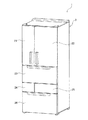
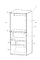
図1及び図2に示すように、本実施形態における冷蔵庫1は、正面を開口とし、内側を複数の部屋に区画された断熱箱体3と、各部屋の正面側の開口を封止する複数の扉21〜26と、を備える。尚、以下の説明において、図1における扉がある方向を正面側、断熱箱体3の内側に位置する方向を背面側として述べる。
(First embodiment)
As shown in FIGS. 1 and 2, the refrigerator 1 in the present embodiment has a heat insulating box 3 whose front is an opening and the inside is partitioned into a plurality of rooms, and a plurality of openings that seal the front opening of each room. Doors 21-26. In the following description, the direction in which the door is located in FIG. 1 will be described as the front side, and the direction located inside the heat insulating box 3 will be described as the back side.
断熱箱体3は、内箱と外箱との間に断熱材としてそれらの対向面のほぼ全面にVIP(Vacuum Insulation Panel)と呼ばれる真空断熱材35を挟み込んで構成されている。尚、図2においては、説明のために冷蔵庫1の向かって右側面板の真空断熱材35を透過させているが、上面板、底面板、左側面板、背面板の全てに真空断熱材35が配設されている。
The heat insulating box 3 is configured by sandwiching a vacuum
この断熱箱体3は、上方から順に冷蔵室11と、野菜室12と、横並びの製氷室13及び第一冷凍室14と、第二冷凍室15の5個の部屋に区画されている。冷蔵室11の正面側の開口には、観音開き式の冷蔵室第一扉21と冷蔵室第二扉22が取り付けられている。また、野菜室12、製氷室13、第一冷凍室14、第二冷凍室15の正面側の開口には、夫々引出し式の野菜室扉23、製氷室扉24、第一冷凍室扉25、第二冷凍室扉26が取り付けられている。
The heat insulation box 3 is partitioned into five rooms of a
冷蔵庫1の扉にも、VIPと呼ばれる真空断熱材35が用いられている。このVIPは、グラスウールのような無機コア材をアルミニウム箔又はアルミニウム蒸着と合成樹脂とのラミネートフィルムで真空パックした構造であるが、製造上厚みを厳密に一定に形成するのが困難であり、厚みに個体差が生じる特性がある。冷蔵庫1の扉は、閉じたときに確実に密閉される必要があり、そのためには外板からガスケット嵌合部材までの距離を一定にする必要がある。そこで、厚みに個体差があるVIPを断熱材として用いながら同一サイズの扉を製造するためには、VIPの厚みの変化を吸収できる構造が必要となる。以下、このようなVIPの厚みの変化に対応できる扉の構造について述べる。
A vacuum
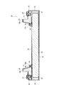
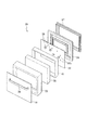
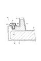
扉の構造の説明のため、代表して第二冷凍室扉26について説明する。図3乃至図5に示すように、第二冷凍室扉26は、外板31と、内板32と、側枠33と、ガスケット嵌合部材40と、スロート部材34と、真空断熱材35と、ファスナー36と、ガスケット37と、取手39と、を備えている。この第二冷凍室扉26では、ガスケット嵌合部材40の枠内側にスロート部材34が連結されて一体に形成されている。
For the description of the door structure, the second
そして、第二冷凍室扉26は、側枠33の正面側端部近傍に外板31が固定され、側枠33の背面側端部近傍にガスケット嵌合部材40及びスロート部材34が固定されている。また、第二冷凍室扉26は、スロート部材34の正面側に内板32が配置され、外板31と内板32との間にそれらのほぼ全対向面を占める広さの真空断熱材35が配置されている。ガスケット嵌合部材40の背面側にはガスケット37が嵌着されている。外板31の正面には取手39が取り付けられている。
In the second
真空断熱材35は、外周部にソフトテープ41が巻装されている。ソフトテープ41は断熱効果を備えた素材であり、例えば、スポンジテープのようなものを用いることができる。真空断熱材35は、正面を外板31に接着固定されている。また、真空断熱材35の背面には、複数のファスナー36が接着などによって固定されている。
As for the vacuum
ファスナー36は、平板である基板36aと、基板36aの中央から背面側に延在する円筒部36bと、からなる。円筒部36bの孔は、後述する螺子42が螺着されるねじ穴である。このファスナー36は、基板36aが真空断熱材35に接着固定され、円筒部36bが内板32を貫通してスロート部材34の端部に当接し、螺子42によってこのスロート部材34の端部を固定している。ファスナー36とスロート部材34が固定された状態では、スロート部材34と一体形成されたガスケット嵌合部材40の正面側端部と真空断熱材35との間に内板32が存在する場合に、内板32の板厚より大である離間距離の離間部44が形成されている。
The
すなわち、スロート部材34におけるファスナー36と当接した部分からガスケット嵌合部材40における正面側端部までの距離をa、ファスナー36の円筒部36bの高さをb、内板32の厚みをcとした場合、b−c>aとなるようにそれぞれが形成されている。
That is, the distance from the portion of the
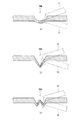
また、スロート部材34の内空側には、例えば発泡スチロール等の断熱材43が予め充填されている。そして、スロート部材34におけるこの断熱材43の近傍に位置する1カ所あるいは複数カ所には、弾性部34kが形成されている。この弾性部34kは、図6(a)に示すように、円弧状に肉厚を薄く形成されてなる。このように弾性部34kを設けることにより、真空断熱材35の厚みが設計よりも厚かったり薄かったりしてファスナー36の位置が若干前後し、その分スロート部材34の端部(ファスナー固定部34b)もその固定位置が前後しても、弾性部34kが変形することでファスナー36の位置に応じてスロート部材34の端部を変位させることができる。図6(a)〜(c)の各図において、(イ)は肉厚が厚い場合の変形例、(ロ)は肉厚が薄い場合の変形例を示している。
In addition, the inner side of the
すなわち、スロート部材34の端部に生じる変形は弾性部34kで吸収されてガスケット嵌合部材40には伝わらないため、外板32とガスケット嵌合部材40との間の距離は一定に保つことができる。よって、本実施形態の第二冷凍室扉26では、スロート部材34の弾性部34kで真空断熱材35の厚みの個体差を吸収できるため、厚みに個体差が生じやすいVIPを用いても厚みが一定の扉を製造できることとなる。
That is, since the deformation generated at the end of the
尚、図6(c)に示すように、スロート部材34における弾性部34kは、薄肉の凹部としたり、その薄肉の凹部を複数設けたりして容易に変形可能にしたり、該当部分だけ容易に変形可能な材質にしたりして形成してもよい。
As shown in FIG. 6 (c), the
以下、さらに詳細に第二冷凍室扉26の構造について述べる。図3乃至図5に示したように、外板31は、方形状の平板であり、側枠33に接着などによって固定されている。また、内板32は、方形状の平板であり、ファスナー36が貫通する複数の貫通孔32aを有する。
Hereinafter, the structure of the second
側枠33は、外板31及びガスケット嵌合部材40が固定される方形状の枠体である。この側枠33は、第二冷凍室扉26の側面を形成する側壁33aと、側壁33aの正面側端部近傍において枠内に突出するように形成された外板固着部33bと、ガスケット嵌合部材40が固定される側壁33aの背面側端部近傍に形成された固定部33cと、を備える。固定部33cは、ガスケット嵌合部材40の正面側角部が当接する前突出部33dと、ガスケット嵌合部材40を前突出部33dとの間で挟み込んで保持する後突出部33eと、からなる。前突出部33d及び後突出部33eは、側壁33aから枠内側へ突出するように形成された線条である。
The
ガスケット嵌合部材40は、スロート部材34の外側に連結された枠体であり、後述するガスケット37の差込部37bが差し込まれる開口を有した中空の箱形形状である。ガスケット嵌合部材40の背面側側端の角部には、側枠33の後突出部33eが係止する段部40aが形成されている。
The
スロート部材34は、第二冷凍室扉26の閉扉時に断熱箱体3の内側に進入して断熱箱体3の内面と重なることにより断熱箱体3内の冷気が漏洩を防止するための部材である。このスロート部材34は矩形の枠状をなしており、外周部分にガスケット嵌合部材40が連結されてガスケット嵌合部材40と一体に形成されている。
The
そして、スロート部材34は、後方(断熱箱体3の内側)に突出する膨出部34aと、膨出部34aの枠内側に位置するファスナー固定部34bとを備える。そして、膨出部34aの内側は中空に形成され、この空間に発泡スチロールなどの断熱材43が充填されている。膨出部34aの後方端面(背面)の適所には上述した弾性部34kが形成されている。ファスナー固定部34bには、螺子42が貫通する複数のねじ穴が形成されている。
And the
ガスケット37は、中空密閉のエアクッション部37aを有した枠体であり、矢尻状の差込部37bを有している。さらに、ガスケット37は、エアクッション部37aの背面側に断熱箱体3の開口部周面に磁着するためのマグネット37cを有している。このガスケット37は柔軟材であり、差込部37bをガスケット嵌合部材40に柔軟性を利用して押し込むことでガスケット嵌合部材40に取り付けられている。
The
そして、第二冷凍室扉26は、側枠33の外板固着部33bに外板31が固定され、側枠33の固定部33cにスロート部材34と一体であるガスケット嵌合部材40が嵌合されている。すなわち、第二冷凍室扉26は、外板31とガスケット嵌合部材40の背面との距離である、扉の厚みが一定とされている。また、第二冷凍室扉26は、外板31の背面側に真空断熱材35が配置され、真空断熱材35の背面側にはファスナー36を介して内板32が配置され、真空断熱材35の背面に接着されている。そして、内板32の背面側に離間部44を介してガスケット嵌合部材40及びスロート部材34が位置している。そして、スロート部材34のファスナー固定部34bは、ファスナー36に螺子42で固定されている。
In the second
このように本実施形態によれば、スロート部材34に弾性部34kを設けることにより、真空断熱材35の厚みによってファスナー36の位置が低くなったり高くなったりしても、弾性部34kの部分が図6において(イ)あるいは(ロ)のように変形することによってファスナー固定部34bが前後してその変位を吸収できる。よって、厚みが常に一定の第二冷凍室扉26を容易に製造できることとなる。
Thus, according to the present embodiment, by providing the
また、ガスケット嵌合部材34aをスロート部材34と一体に形成することにより、扉の組み立て工程を減らすことができ、製造コストの削減が図れる。
Further, by forming the
尚、ファスナー36と真空断熱材35との固定方法は接着に限らず、面ファスナーなどを用いてもよい。また、冷蔵庫1の扉の代表として第二冷凍室扉26について述べたが、同様の構成を他の扉にも適用できる。
The fixing method between the
また、上記実施形態では弾性部34kをスロート部材34の後端面に設けたが、図7に示すように、ガスケット嵌合部材40とスロート部材34とを連結する面に設ける構成としてもよい。これにより、真空断熱材35の厚みの個体差を、ガスケット嵌合部材40の位置は変化させずに、スロート部材34の全体の前後の変位により吸収することができる。
Moreover, although the
(第2の実施の形態)
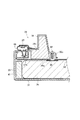
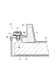
次に、冷蔵庫1の扉の構造に関する第2の実施の形態を述べる。図8に示すように、本実施の形態における第二冷凍室扉26は、ガスケット嵌合部材40が外板31と直接固定されていることを特徴とする。尚、以下の説明において、第1の実施の形態と共通する部材には共通する符号を用いて述べる。
(Second Embodiment)
Next, 2nd Embodiment regarding the structure of the door of the refrigerator 1 is described. As shown in FIG. 8, the second
第二冷凍室扉26は、扁平で箱形の外板31と、平板状の内板32と、外板31と内板32の間に挟み込まれる真空断熱材35と、一体に形成されたガスケット嵌合部材40及びスロート部材34と、ファスナー36と、ガスケット37と、を備える。
The second
外板31は、側壁に後述するガスケット嵌合部材40の爪40cが嵌合する嵌合孔31aを備えている。また、ガスケット嵌合部材40は、外側端部に正面側に延在する側壁40bを備え、側壁40bの正面側端部近傍に爪40cが形成されている。さらに、上記実施形態と同様に、スロート部材34は、弾性部34kを有しており、内空部分には断熱材43が充填されている。
The
そして、第二冷凍室扉26は、外板31の背面に真空断熱材35が接着され、真空断熱材35の背面側にファスナー36を介して内板32が配置され、内板32の背面側に離間部44が形成された状態でガスケット嵌合部材40及びスロート部材34が配置されている。また、ガスケット嵌合部材40は、外板31の嵌合孔31aに爪40cが嵌合することで外板31と固定されている。このように、ガスケット嵌合部材40と外板31は嵌合されているため、ガスケット嵌合部材40と外板31の距離、すなわち、第二冷凍室扉26の厚みは常に一定となる。その他の構成は、第1の実施の形態と共通しているため、詳細な説明は省略する。
In the second
本実施の形態における第二冷凍室扉26においても、上記実施形態と同様に真空断熱材35とガスケット嵌合部材40の正面側端部との間に内板32が存在する場合に、内板32の板厚より大である離間距離の離間部44が形成されているため、真空断熱材35の個体差による厚みの変化があっても、第二冷凍室扉26の厚みを一定に保ったまま扉を容易に製造できることとなる。
Also in the second
(第3の実施の形態)
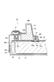
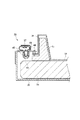
次に、冷蔵庫1の扉の構造に関する第3の実施の形態を述べる。図9に示すように、本実施の形態における第二冷凍室扉26では、ガスケット嵌合部材40と、スロート部材34と内板32と、が一体に形成されている。すなわち、第二冷凍室扉26は、外板31と、一体に形成された内板32、ガスケット嵌合部材40、スロート部材34と、外板31と内板32との間に挟み込まれる真空断熱材35と、側枠33と、ガスケット37と、を備えてなる。
(Third embodiment)
Next, a third embodiment relating to the door structure of the refrigerator 1 will be described. As shown in FIG. 9, in the 2nd
外板31は、側枠33の正面側端部に固定され、ガスケット嵌合部材40は側枠33の後方端部近傍に固定されている。ガスケット嵌合部材40とスロート部材34との連結面には弾性部34kが形成されている。真空断熱材35は、正面が外板31に接着され、背面が内板32に接着されている。また、真空断熱材35とガスケット嵌合部材40の正面側端部との間には、内板32が介在することなく、離間部44が形成されている。
The
本実施の形態における第二冷凍室扉26では、真空断熱材35の厚みが厚い場合、内板32が後方に押し出されることになる。しかし、ガスケット嵌合部材40とスロート部材34との間の弾性部34kが変形することによって厚みの差を吸収し、内板32及びスロート部材34が後方に押し出されてもガスケット嵌合部材40は変位しない。よって、外板31とガスケット嵌合部材40との距離が一定であって、厚みに個体差がある真空断熱材35を断熱材として用いた扉を容易に製造できることとなる。
In the second
また本実施の形態の場合、内板32、ガスケット嵌合部材40、スロート部材34を一体に形成しているため、扉の組み立てが容易となり、製造コストを削減することができる。
In the case of this embodiment, since the
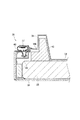
(第4の実施の形態)
次に、冷蔵庫1の扉の構造に関する第4の実施の形態を述べる。図10に示すように、本実施の形態における第二冷凍室扉26も第3の実施の形態と同様に、内板32、ガスケット嵌合部材40、スロート部材34が一体に形成されている。また、外板31が扁平の箱形であり、外板31とガスケット嵌合部材40が直接嵌合されている。
(Fourth embodiment)
Next, a fourth embodiment relating to the structure of the door of the refrigerator 1 will be described. As shown in FIG. 10, in the second
本実施の形態における第二冷凍室扉26においてもガスケット嵌合部材40の正面側端部と真空断熱材35との間には、内板32が介在することなく、離間部44が形成されている。また、ガスケット嵌合部材40とスロート部材34との間には弾性部34kが形成されている。そして、真空断熱材35は、正面が外板31に接着され、背面が内板32に接着されている。
Also in the second
本実施の形態でも、外板31とガスケット嵌合部材40との距離が一定でドア厚みを一定にしながら、厚みに個体差がある真空断熱材35を断熱材として用いた扉を容易に製造できることとなる。
Even in the present embodiment, the distance between the
尚、図11に示すように、ガスケット嵌合部材40と外板31が螺子46等によって、あるいはツメなどの嵌合手段によって連結された構造であっても、離間部44、弾性部34kを設けることで同様の効果を得ることができる。
As shown in FIG. 11, even if the
(第5の実施の形態)
次に、冷蔵庫1の扉の構造に関する第5の実施の形態を述べる。図12に示すように、本実施の形態における第二冷凍室扉26では、内板32とスロート部材34が一体形成されている。すなわち、本実施形態における第二冷凍室扉26は、外板31と、スロート部材34と一体形成された内板32と、ガスケット嵌合部材40と、外板31と内板32との間に挟み込まれた真空断熱材35と、ガスケット37と、を備える。
(Fifth embodiment)
Next, a fifth embodiment relating to the door structure of the refrigerator 1 will be described. As shown in FIG. 12, in the 2nd
外板31は、扁平の箱形形状である。ガスケット嵌合部材40は、外板31の外周に嵌め込まれる側壁40dを有した方形状の枠体である。そして、外板31の後端にガスケット嵌合部材40が嵌合され、ねじ46にて連結されている。このねじ46に代えて接着接合してもよい。
The
また、第二冷凍室扉26は、外板31の背面に真空断熱材35が接着され、真空断熱材35の背面に内板32が接着されている。内板32と一体形成されたスロート部材34は、ガスケット嵌合部材40に対して間隔を開けた状態で配置されており、スロート部材34とガスケット嵌合部材40は螺子48によって連結されている。そしてねじ48にはバネのような弾性体49が装着してあり、この弾性体49によりスロート部材34の端部とガスケット嵌合部材40との間隔の広狭を吸収するようにしている。尚、上述した各実施形態と同様に、ガスケット嵌合部材40の正面側端部と真空断熱材35との間には、内板32が介在することなく、離間部44が形成されている。
The second
このような構成とされた第二冷凍室扉26でも、又は厚みに個体差がある真空断熱材35を断熱材として用いながらも、その厚みの変化を吸収し、一定の厚さの扉を製造できることとなる。
Even in the second
本発明のいくつかの実施形態を説明したが、これらの実施形態は、例として提示したものであり、発明の範囲を限定することは意図していない。これら新規な実施形態は、その他の様々な形態で実施されることが可能であり、発明の要旨を逸脱しない範囲で、種々の省略、置き換え、変更を行うことができる。これら実施形態やその変形は、発明の範囲や要旨に含まれるとともに、特許請求の範囲に記載された発明とその均等の範囲に含まれる。 Although several embodiments of the present invention have been described, these embodiments are presented by way of example and are not intended to limit the scope of the invention. These novel embodiments can be implemented in various other forms, and various omissions, replacements, and changes can be made without departing from the scope of the invention. These embodiments and modifications thereof are included in the scope and gist of the invention, and are included in the invention described in the claims and the equivalents thereof.
1 冷蔵庫
3 断熱箱体
11 冷蔵室
12 野菜室
13 製氷室
14 第一冷凍室
15 第二冷凍室
21 冷蔵室第一扉
22 冷蔵室第二扉
23 野菜室扉
24 製氷室扉
25 第一冷凍室扉
26 第二冷凍室扉
31 外板
31a 嵌合孔
32 内板
32a 貫通孔
33 側枠
33a 側壁
33b 外板固着部
33c 固定部
33d 前突出部
33e 後突出部
34 スロート部材
34a 膨出部
34b ファスナー固定部
34k 弾性部
35 真空断熱材
36 ファスナー
36a 基板
36b 円筒部
37 ガスケット
37a エアクッション部
37b 差込部
37c マグネット
39 取手
40 ガスケット嵌合部材
40a 段部
40b 側壁
40c 爪
41 ソフトテープ
42 螺子
43 断熱材
44 離間部
46 螺子
48 螺子
49 弾性体
DESCRIPTION OF SYMBOLS 1 Refrigerator 3
Claims (8)
前記扉は、外板と、該外板と対向するように配置される内板と、前記外板と内板との間に挟み込まれるように配置される真空断熱材と、扉の内側側端近傍に全周に渡って取り付けられるガスケットと、前記ガスケットが嵌合される枠状のガスケット嵌合部材と、前記扉を閉じたときに前記断熱箱体の内側に入り込んで冷気の流出を防止する枠状のスロート部材と、を備え、
前記外板から前記ガスケット嵌合部材までの距離は一定とし、前記ガスケット嵌合部材の正面側端部と前記真空断熱材の背面との間に離間部を形成し、当該正面側端部と当該背面を互いに非接触にしたことを特徴とする冷蔵庫。 It is a refrigerator having a heat insulating material filled between an inner box and an outer box, and having a heat insulating box with an opening at the front, and a door for closing the opening at the front of the heat insulating box,
The door includes an outer plate, an inner plate arranged to face the outer plate, a vacuum heat insulating material arranged to be sandwiched between the outer plate and the inner plate, and an inner side end of the door A gasket attached to the entire periphery in the vicinity, a frame-shaped gasket fitting member into which the gasket is fitted, and an inside of the heat insulating box when the door is closed to prevent the outflow of cold air A frame-shaped throat member,
The distance from the outer plate to the gasket fitting member is constant, a separation portion is formed between the front side end of the gasket fitting member and the back surface of the vacuum heat insulating material, and the front side end and the A refrigerator characterized in that the back surfaces are not in contact with each other .
前記真空断熱材の背面に基部を固定した取付部の先端の突出部を、前記内板を貫通させ、前記スロート部材の端部に連結したことを特徴とする請求項1又は2に記載の冷蔵庫。 The throat member and the gasket fitting member are disposed on the back side of the inner plate,
The refrigerator according to claim 1 or 2, wherein a protruding portion at a tip of a mounting portion having a base fixed to the back surface of the vacuum heat insulating material is connected to an end portion of the throat member through the inner plate. .
又は The refrigerator according to any one of claims 1 to 3, wherein an elastic part that can be easily deformed is provided between the throat member and the gasket fitting member or in the throat member.
Or
Priority Applications (5)
| Application Number | Priority Date | Filing Date | Title |
|---|---|---|---|
| JP2012063803A JP6081069B2 (en) | 2012-03-21 | 2012-03-21 | refrigerator |
| EP12872109.9A EP2829827A4 (en) | 2012-03-21 | 2012-11-08 | FRIDGE |
| CN201280071589.3A CN104254749B (en) | 2012-03-21 | 2012-11-08 | Refrigerator |
| PCT/JP2012/078960 WO2013140658A1 (en) | 2012-03-21 | 2012-11-08 | Refrigerator |
| TW101142436A TWI519750B (en) | 2012-03-21 | 2012-11-14 | refrigerator |
Applications Claiming Priority (1)
| Application Number | Priority Date | Filing Date | Title |
|---|---|---|---|
| JP2012063803A JP6081069B2 (en) | 2012-03-21 | 2012-03-21 | refrigerator |
Publications (2)
| Publication Number | Publication Date |
|---|---|
| JP2013195009A JP2013195009A (en) | 2013-09-30 |
| JP6081069B2 true JP6081069B2 (en) | 2017-02-15 |
Family
ID=49222146
Family Applications (1)
| Application Number | Title | Priority Date | Filing Date |
|---|---|---|---|
| JP2012063803A Expired - Fee Related JP6081069B2 (en) | 2012-03-21 | 2012-03-21 | refrigerator |
Country Status (5)
| Country | Link |
|---|---|
| EP (1) | EP2829827A4 (en) |
| JP (1) | JP6081069B2 (en) |
| CN (1) | CN104254749B (en) |
| TW (1) | TWI519750B (en) |
| WO (1) | WO2013140658A1 (en) |
Cited By (2)
| Publication number | Priority date | Publication date | Assignee | Title |
|---|---|---|---|---|
| JP2017090045A (en) * | 2017-02-27 | 2017-05-25 | 東芝ライフスタイル株式会社 | refrigerator |
| JP2019109048A (en) * | 2019-04-12 | 2019-07-04 | 東芝ライフスタイル株式会社 | refrigerator |
Families Citing this family (58)
| Publication number | Priority date | Publication date | Assignee | Title |
|---|---|---|---|---|
| US8986483B2 (en) | 2012-04-02 | 2015-03-24 | Whirlpool Corporation | Method of making a folded vacuum insulated structure |
| US9221210B2 (en) | 2012-04-11 | 2015-12-29 | Whirlpool Corporation | Method to create vacuum insulated cabinets for refrigerators |
| JP6105242B2 (en) * | 2012-09-25 | 2017-03-29 | 東芝ライフスタイル株式会社 | refrigerator |
| US9599392B2 (en) | 2014-02-24 | 2017-03-21 | Whirlpool Corporation | Folding approach to create a 3D vacuum insulated door from 2D flat vacuum insulation panels |
| US9689604B2 (en) | 2014-02-24 | 2017-06-27 | Whirlpool Corporation | Multi-section core vacuum insulation panels with hybrid barrier film envelope |
| US10052819B2 (en) | 2014-02-24 | 2018-08-21 | Whirlpool Corporation | Vacuum packaged 3D vacuum insulated door structure and method therefor using a tooling fixture |
| DE102014214102A1 (en) * | 2014-07-21 | 2016-01-21 | BSH Hausgeräte GmbH | Wall for a household refrigerating appliance, household refrigerating appliances and method for producing a wall |
| US9389013B2 (en) | 2014-08-15 | 2016-07-12 | Anthony International | Thermal frame for a refrigerated enclosure |
| US9476633B2 (en) | 2015-03-02 | 2016-10-25 | Whirlpool Corporation | 3D vacuum panel and a folding approach to create the 3D vacuum panel from a 2D vacuum panel of non-uniform thickness |
| US10161669B2 (en) | 2015-03-05 | 2018-12-25 | Whirlpool Corporation | Attachment arrangement for vacuum insulated door |
| US9897370B2 (en) | 2015-03-11 | 2018-02-20 | Whirlpool Corporation | Self-contained pantry box system for insertion into an appliance |
| US9441779B1 (en) | 2015-07-01 | 2016-09-13 | Whirlpool Corporation | Split hybrid insulation structure for an appliance |
| KR102525551B1 (en) * | 2015-08-03 | 2023-04-25 | 엘지전자 주식회사 | Vacuum adiabatic body and refrigerator |
| KR102502160B1 (en) | 2015-08-03 | 2023-02-21 | 엘지전자 주식회사 | Vacuum adiabatic body and refrigerator |
| KR20170016188A (en) | 2015-08-03 | 2017-02-13 | 엘지전자 주식회사 | Vacuum adiabatic body and refrigerator |
| EP3332193B1 (en) * | 2015-08-03 | 2021-11-17 | LG Electronics Inc. | Vacuum adiabatic body |
| KR102525550B1 (en) | 2015-08-03 | 2023-04-25 | 엘지전자 주식회사 | Vacuum adiabatic body and refrigerator |
| KR102466469B1 (en) | 2015-08-03 | 2022-11-11 | 엘지전자 주식회사 | Vacuum adiabatic body and refrigerator |
| KR102447245B1 (en) * | 2015-08-03 | 2022-09-27 | 엘지전자 주식회사 | Vacuum insulator and refrigerator |
| KR102514039B1 (en) * | 2015-08-03 | 2023-03-24 | 엘지전자 주식회사 | Vacuum adiabatic body and refrigerator |
| KR102498210B1 (en) | 2015-08-03 | 2023-02-09 | 엘지전자 주식회사 | Vacuum adiabatic body and refrigerator |
| KR102456642B1 (en) * | 2015-08-03 | 2022-10-19 | 엘지전자 주식회사 | Vacuum adiabatic body and refrigerator |
| KR102442973B1 (en) | 2015-08-03 | 2022-09-14 | 엘지전자 주식회사 | Vacuum insulator and refrigerator |
| KR102529853B1 (en) | 2015-08-03 | 2023-05-08 | 엘지전자 주식회사 | Vacuum adiabatic body, fabricating method for the Vacuum adiabatic body, porous substance package, and refrigerator |
| KR102497139B1 (en) | 2015-08-03 | 2023-02-07 | 엘지전자 주식회사 | Vacuum adiabatic body |
| KR102529852B1 (en) * | 2015-08-03 | 2023-05-08 | 엘지전자 주식회사 | Vacuum adiabatic body and refrigerator |
| KR102466470B1 (en) | 2015-08-04 | 2022-11-11 | 엘지전자 주식회사 | Vacuum adiabatic body and refrigerator |
| US10429125B2 (en) | 2015-12-08 | 2019-10-01 | Whirlpool Corporation | Insulation structure for an appliance having a uniformly mixed multi-component insulation material, and a method for even distribution of material combinations therein |
| US10041724B2 (en) | 2015-12-08 | 2018-08-07 | Whirlpool Corporation | Methods for dispensing and compacting insulation materials into a vacuum sealed structure |
| US10222116B2 (en) | 2015-12-08 | 2019-03-05 | Whirlpool Corporation | Method and apparatus for forming a vacuum insulated structure for an appliance having a pressing mechanism incorporated within an insulation delivery system |
| US11052579B2 (en) | 2015-12-08 | 2021-07-06 | Whirlpool Corporation | Method for preparing a densified insulation material for use in appliance insulated structure |
| US10422573B2 (en) | 2015-12-08 | 2019-09-24 | Whirlpool Corporation | Insulation structure for an appliance having a uniformly mixed multi-component insulation material, and a method for even distribution of material combinations therein |
| US12508751B2 (en) | 2015-12-08 | 2025-12-30 | Whirlpool Corporation | Insulation compaction device and method for forming an insulated structure for an appliance |
| US10422569B2 (en) | 2015-12-21 | 2019-09-24 | Whirlpool Corporation | Vacuum insulated door construction |
| US9840042B2 (en) | 2015-12-22 | 2017-12-12 | Whirlpool Corporation | Adhesively secured vacuum insulated panels for refrigerators |
| US9752818B2 (en) | 2015-12-22 | 2017-09-05 | Whirlpool Corporation | Umbilical for pass through in vacuum insulated refrigerator structures |
| US10018406B2 (en) | 2015-12-28 | 2018-07-10 | Whirlpool Corporation | Multi-layer gas barrier materials for vacuum insulated structure |
| US10610985B2 (en) | 2015-12-28 | 2020-04-07 | Whirlpool Corporation | Multilayer barrier materials with PVD or plasma coating for vacuum insulated structure |
| US10030905B2 (en) | 2015-12-29 | 2018-07-24 | Whirlpool Corporation | Method of fabricating a vacuum insulated appliance structure |
| US10807298B2 (en) | 2015-12-29 | 2020-10-20 | Whirlpool Corporation | Molded gas barrier parts for vacuum insulated structure |
| US11247369B2 (en) | 2015-12-30 | 2022-02-15 | Whirlpool Corporation | Method of fabricating 3D vacuum insulated refrigerator structure having core material |
| EP3443285B1 (en) | 2016-04-15 | 2021-03-10 | Whirlpool Corporation | Vacuum insulated refrigerator cabinet |
| EP3443284B1 (en) | 2016-04-15 | 2020-11-18 | Whirlpool Corporation | Vacuum insulated refrigerator structure with three dimensional characteristics |
| EP3491308B1 (en) | 2016-07-26 | 2021-03-10 | Whirlpool Corporation | Vacuum insulated structure trim breaker |
| EP3500804B1 (en) | 2016-08-18 | 2022-06-22 | Whirlpool Corporation | Refrigerator cabinet |
| JP6854106B2 (en) * | 2016-10-13 | 2021-04-07 | 東芝ライフスタイル株式会社 | refrigerator |
| EP3548813B1 (en) | 2016-12-02 | 2023-05-31 | Whirlpool Corporation | Hinge support assembly |
| KR102902150B1 (en) * | 2017-01-03 | 2025-12-19 | 삼성전자주식회사 | Refrigerator |
| WO2019208457A1 (en) * | 2018-04-26 | 2019-10-31 | パナソニックIpマネジメント株式会社 | Refrigerator |
| DE102018207625A1 (en) * | 2018-05-16 | 2019-11-21 | BSH Hausgeräte GmbH | Sealing element with closure part in the form of a ring section, door with a sealing element and household appliance |
| CN108981274A (en) * | 2018-05-31 | 2018-12-11 | 东芝家用电器制造(南海)有限公司 | Refrigerator |
| US10907888B2 (en) | 2018-06-25 | 2021-02-02 | Whirlpool Corporation | Hybrid pigmented hot stitched color liner system |
| KR102568407B1 (en) | 2018-06-27 | 2023-08-21 | 엘지전자 주식회사 | Vacuum adiabatic body and refrigerator |
| US10907891B2 (en) | 2019-02-18 | 2021-02-02 | Whirlpool Corporation | Trim breaker for a structural cabinet that incorporates a structural glass contact surface |
| KR102896121B1 (en) * | 2019-07-09 | 2025-12-05 | 엘지전자 주식회사 | Vacuum adiabatic body and refrigerator |
| JP7499014B2 (en) * | 2019-10-08 | 2024-06-13 | 日立グローバルライフソリューションズ株式会社 | Insulated refrigerator door and refrigerator |
| WO2022092963A1 (en) * | 2020-11-02 | 2022-05-05 | Lg Electronics Inc. | Vacuum adiabatic body |
| EP4237771A4 (en) * | 2020-11-02 | 2024-09-11 | LG Electronics Inc. | Vacuum adiabatic body |
Family Cites Families (26)
| Publication number | Priority date | Publication date | Assignee | Title |
|---|---|---|---|---|
| GB729393A (en) * | 1952-07-09 | 1955-05-04 | Gen Electric | Improvements in and relating to insulated door structures |
| JPS5750688U (en) * | 1980-09-10 | 1982-03-23 | ||
| JPS5911291U (en) * | 1982-07-14 | 1984-01-24 | 松下冷機株式会社 | insulation wall |
| JPS5966679A (en) * | 1982-10-06 | 1984-04-16 | 株式会社日立製作所 | Door of refrigerator |
| JPS6055976U (en) * | 1983-09-26 | 1985-04-19 | 株式会社東芝 | refrigerator insulated door |
| IT8434032U1 (en) * | 1984-05-24 | 1985-11-24 | Zanussi Elettrodomestici | Refrigerator door |
| JPS60191889U (en) * | 1984-05-29 | 1985-12-19 | 株式会社東芝 | insulation door |
| JPS613387U (en) * | 1984-06-12 | 1986-01-10 | 三菱電機株式会社 | refrigerator |
| JPS613389U (en) * | 1984-06-12 | 1986-01-10 | 松下冷機株式会社 | refrigerator door |
| JPH07234067A (en) * | 1994-02-21 | 1995-09-05 | Hitachi Ltd | Vacuum insulation doors for refrigerators, etc. |
| JPH0814485A (en) * | 1994-06-29 | 1996-01-16 | Sanyo Electric Co Ltd | Heat insulating body structure |
| KR0186124B1 (en) * | 1995-12-29 | 1999-04-15 | 이종수 | Insulation Case of Vending Machine |
| JP3547914B2 (en) * | 1996-09-24 | 2004-07-28 | 三菱電機株式会社 | Gaskets for refrigerators and refrigerators |
| TR199700083A2 (en) * | 1997-02-03 | 1998-08-21 | Ar�El�K A.�. | Refrigerator door with high insulation and recycling performance. |
| JP3872161B2 (en) * | 1997-04-18 | 2007-01-24 | 松下冷機株式会社 | Refrigerator door |
| JP3546345B2 (en) * | 1997-12-05 | 2004-07-28 | 三菱電機株式会社 | Freezer refrigerator |
| JPH11353544A (en) * | 1998-06-04 | 1999-12-24 | Sanden Corp | Assembling structure for heat insulation casing |
| JP2001091147A (en) * | 1999-09-27 | 2001-04-06 | Matsushita Refrig Co Ltd | Heat insulation door and storage chamber equipped therewith |
| JP2004116695A (en) * | 2002-09-27 | 2004-04-15 | Nisshinbo Ind Inc | Vacuum insulation board and heat insulation container using the vacuum insulation board |
| JP3862170B2 (en) * | 2003-01-30 | 2006-12-27 | 富士電機リテイルシステムズ株式会社 | Insulation board and vending machine |
| JP2005275642A (en) * | 2004-03-24 | 2005-10-06 | Fuji Electric Retail Systems Co Ltd | Heat insulating panel for vending machine and vending machine |
| JP4198103B2 (en) | 2004-09-24 | 2008-12-17 | 三洋電機株式会社 | Refrigerator door device |
| JP5098149B2 (en) * | 2005-10-27 | 2012-12-12 | パナソニック株式会社 | vending machine |
| JP5303397B2 (en) * | 2009-08-12 | 2013-10-02 | 日立アプライアンス株式会社 | refrigerator |
| JP5193980B2 (en) * | 2009-09-28 | 2013-05-08 | 日立アプライアンス株式会社 | refrigerator |
| JP5513855B2 (en) * | 2009-11-11 | 2014-06-04 | 株式会社東芝 | refrigerator |
-
2012
- 2012-03-21 JP JP2012063803A patent/JP6081069B2/en not_active Expired - Fee Related
- 2012-11-08 WO PCT/JP2012/078960 patent/WO2013140658A1/en not_active Ceased
- 2012-11-08 CN CN201280071589.3A patent/CN104254749B/en not_active Expired - Fee Related
- 2012-11-08 EP EP12872109.9A patent/EP2829827A4/en not_active Withdrawn
- 2012-11-14 TW TW101142436A patent/TWI519750B/en not_active IP Right Cessation
Cited By (2)
| Publication number | Priority date | Publication date | Assignee | Title |
|---|---|---|---|---|
| JP2017090045A (en) * | 2017-02-27 | 2017-05-25 | 東芝ライフスタイル株式会社 | refrigerator |
| JP2019109048A (en) * | 2019-04-12 | 2019-07-04 | 東芝ライフスタイル株式会社 | refrigerator |
Also Published As
| Publication number | Publication date |
|---|---|
| EP2829827A1 (en) | 2015-01-28 |
| CN104254749B (en) | 2016-10-26 |
| WO2013140658A1 (en) | 2013-09-26 |
| JP2013195009A (en) | 2013-09-30 |
| EP2829827A4 (en) | 2015-11-18 |
| TW201341740A (en) | 2013-10-16 |
| CN104254749A (en) | 2014-12-31 |
| TWI519750B (en) | 2016-02-01 |
Similar Documents
| Publication | Publication Date | Title |
|---|---|---|
| JP6081069B2 (en) | refrigerator | |
| JP6081108B2 (en) | refrigerator | |
| JP6005341B2 (en) | refrigerator | |
| KR102222572B1 (en) | Refrigerator | |
| TWI605233B (en) | Refrigerator door and refrigerator | |
| JP5931355B2 (en) | Heat insulation box | |
| JP2021038921A (en) | refrigerator | |
| KR20160084020A (en) | Refrigerator and display unit of a refrigerator | |
| JP5959225B2 (en) | refrigerator | |
| TWI727629B (en) | refrigerator | |
| JP6081064B2 (en) | refrigerator | |
| US20180259243A1 (en) | Refrigerator | |
| JP6688339B2 (en) | refrigerator | |
| WO2016135808A1 (en) | Heat-insulation housing, heat-insulation door, and refrigerator | |
| JP6360685B2 (en) | refrigerator | |
| JP6363234B2 (en) | refrigerator | |
| JP2019138532A (en) | refrigerator | |
| JP6301999B2 (en) | Heat insulation box | |
| JP6887540B2 (en) | refrigerator | |
| JP2025042795A (en) | refrigerator |
Legal Events
| Date | Code | Title | Description |
|---|---|---|---|
| A711 | Notification of change in applicant |
Free format text: JAPANESE INTERMEDIATE CODE: A712 Effective date: 20140128 |
|
| A621 | Written request for application examination |
Free format text: JAPANESE INTERMEDIATE CODE: A621 Effective date: 20141209 |
|
| A131 | Notification of reasons for refusal |
Free format text: JAPANESE INTERMEDIATE CODE: A131 Effective date: 20160329 |
|
| A521 | Request for written amendment filed |
Free format text: JAPANESE INTERMEDIATE CODE: A523 Effective date: 20160524 |
|
| A711 | Notification of change in applicant |
Free format text: JAPANESE INTERMEDIATE CODE: A711 Effective date: 20160622 |
|
| A131 | Notification of reasons for refusal |
Free format text: JAPANESE INTERMEDIATE CODE: A131 Effective date: 20161011 |
|
| A521 | Request for written amendment filed |
Free format text: JAPANESE INTERMEDIATE CODE: A523 Effective date: 20161205 |
|
| TRDD | Decision of grant or rejection written | ||
| A01 | Written decision to grant a patent or to grant a registration (utility model) |
Free format text: JAPANESE INTERMEDIATE CODE: A01 Effective date: 20161220 |
|
| A61 | First payment of annual fees (during grant procedure) |
Free format text: JAPANESE INTERMEDIATE CODE: A61 Effective date: 20170118 |
|
| R150 | Certificate of patent or registration of utility model |
Ref document number: 6081069 Country of ref document: JP Free format text: JAPANESE INTERMEDIATE CODE: R150 |
|
| LAPS | Cancellation because of no payment of annual fees |