JP6077662B2 - Motorcycle - Google Patents
Motorcycle Download PDFInfo
- Publication number
- JP6077662B2 JP6077662B2 JP2015534030A JP2015534030A JP6077662B2 JP 6077662 B2 JP6077662 B2 JP 6077662B2 JP 2015534030 A JP2015534030 A JP 2015534030A JP 2015534030 A JP2015534030 A JP 2015534030A JP 6077662 B2 JP6077662 B2 JP 6077662B2
- Authority
- JP
- Japan
- Prior art keywords
- brake
- step holder
- pedal
- swing arm
- disposed
- Prior art date
- Legal status (The legal status is an assumption and is not a legal conclusion. Google has not performed a legal analysis and makes no representation as to the accuracy of the status listed.)
- Active
Links
Images


Classifications
-
- B—PERFORMING OPERATIONS; TRANSPORTING
- B62—LAND VEHICLES FOR TRAVELLING OTHERWISE THAN ON RAILS
- B62L—BRAKES SPECIALLY ADAPTED FOR CYCLES
- B62L3/00—Brake-actuating mechanisms; Arrangements thereof
- B62L3/04—Brake-actuating mechanisms; Arrangements thereof for control by a foot lever
-
- B—PERFORMING OPERATIONS; TRANSPORTING
- B62—LAND VEHICLES FOR TRAVELLING OTHERWISE THAN ON RAILS
- B62K—CYCLES; CYCLE FRAMES; CYCLE STEERING DEVICES; RIDER-OPERATED TERMINAL CONTROLS SPECIALLY ADAPTED FOR CYCLES; CYCLE AXLE SUSPENSIONS; CYCLE SIDE-CARS, FORECARS, OR THE LIKE
- B62K19/00—Cycle frames
- B62K19/30—Frame parts shaped to receive other cycle parts or accessories
- B62K19/38—Frame parts shaped to receive other cycle parts or accessories for attaching brake members
Description
本発明は、タンデム型の乗車用シートを支持する車体フレームの一部を構成するピボットフレームと、後輪を後端部で軸支するとともに前端部が支軸を介して前記ピボットフレームに揺動可能に支承されるスイングアームと、同乗者が足を載せることを可能としたピリオンステップが取付けられるとともに前記車体フレームに固定されるステップホルダと、前記ステップホルダに設けられたペダル軸を介して該ステップホルダに回動可能に支承されるブレーキペダルとを備え、前記ピボットフレームの前方に内燃機関の機関本体が配置される自動二輪車に関する。 The present invention provides a pivot frame that constitutes a part of a vehicle body frame that supports a tandem riding seat, a rear wheel that is pivotally supported at a rear end portion, and a front end portion that swings on the pivot frame via a pivot shaft. A swing arm that is supported, a pillion step that allows a passenger to put a foot on it, a step holder that is fixed to the vehicle body frame, and a pedal shaft provided on the step holder, The present invention relates to a motorcycle including a brake pedal rotatably supported on a step holder, and an engine body of an internal combustion engine disposed in front of the pivot frame.
車体フレームのピボットフレームに、車幅方向で該ピボットフレームの外側に配置されるステップホルダが固定され、該ステップホルダに、同乗者が足を載せることを可能としたピリオンステップが取付けられるとともに、ブレーキペダルが回動可能に支承されるようにした自動二輪車が、特許文献1で知られている。 A step holder disposed outside the pivot frame in the vehicle width direction is fixed to the pivot frame of the vehicle body frame, and a pillion step that allows a passenger to place a foot is attached to the step holder, and a brake A motorcycle in which a pedal is rotatably supported is known from Patent Document 1.
上記特許文献1で開示された自動二輪車では、車体フレームに搭載される内燃機関の排気管が、側面視で前記ピボットフレームおよび前記ステップホルダの下方を通るように配置されているので、車幅方向でブレーキペダルのステップホルダへの取付けに制約を受けることはないが、ブレーキペダルの車幅方向側方に排気装置が配設されるような自動二輪車では、ブレーキペダルのステップホルダへの支持レイアウトに大きな影響が及ぶことになる。 In the motorcycle disclosed in Patent Document 1, the exhaust pipe of the internal combustion engine mounted on the vehicle body frame is disposed so as to pass below the pivot frame and the step holder in a side view. However, in a motorcycle in which an exhaust device is installed on the side of the brake pedal in the vehicle width direction, there is no restriction on the support layout of the brake pedal to the step holder. It will have a big impact.
本発明は、かかる事情に鑑みてなされたものであり、ブレーキペダルの車幅方向側方に排気装置が配設されていてもブレーキペダルを充分な支持力でステップホルダに支持し得るようにした自動二輪車を提供することを目的とする。 The present invention has been made in view of such circumstances, and the brake pedal can be supported on the step holder with a sufficient supporting force even if an exhaust device is disposed on the side of the brake pedal in the vehicle width direction. The object is to provide a motorcycle.
上記目的を達成するために、本発明は、タンデム型の乗車用シートを支持する車体フレームの一部を構成するピボットフレームと、後輪を後端部で軸支するとともに前端部が支軸を介して前記ピボットフレームに揺動可能に支承されるスイングアームと、同乗者が足を載せることを可能としたピリオンステップが取付けられるとともに前記車体フレームに固定されるステップホルダと、前記ステップホルダに設けられたペダル軸を介して該ステップホルダに回動可能に支承されるブレーキペダルとを備え、前記ピボットフレームの前方に内燃機関の機関本体が配置される自動二輪車において、前記ステップホルダは、前記ピボットフレームの車幅方向外側に配置されるとともに該ピボットフレームに固定される支持部と、側面視で前記スイングアームの下方まで延びるようにして前記支持部から下方に延びる上下延出部とを一体に有するように形成され、前記ブレーキペダルは、車幅方向で前記スイングアームおよび前記ステップホルダ間に配置されるようにして上下に延びる縦アーム部を有するように形成されて、側面視で前記スイングアームよりも下方で前記上下延出部に支承され、前記ペダル軸は、平面視でそれの幅内において前記スイングアームと交差するとともに、該ペダル軸の少なくとも一部は、前記内燃機関の排気装置の一部に側面視で重なる位置に配置され、前輪に設けられたディスクブレーキをブレーキ作動させる液圧を発生することを可能として前記ステップホルダに取付けられるマスタシリンダに一端部が連結され、且つブレーキ操作力を後輪に設けられたドラムブレーキに機械的に伝達するブレーキ操作力伝達部材に他端部が連結されるイコライザの中間部が、前記縦アーム部の裏側で該縦アーム部に連結されて、前記ブレーキペダルから入力されるブレーキ操作力を前記マスタシリンダと前記ブレーキ操作力伝達部材とに分配することを第1の特徴とする。 In order to achieve the above object, the present invention provides a pivot frame that constitutes a part of a vehicle body frame that supports a tandem riding seat, a rear wheel that pivots at the rear end, and a front end that pivots on the pivot. A swing arm that is swingably supported by the pivot frame, a pillion step that allows a passenger to place a foot on it, and a step holder that is fixed to the vehicle body frame, and is provided on the step holder And a brake pedal rotatably supported by the step holder via a pedal shaft, wherein the engine body of the internal combustion engine is disposed in front of the pivot frame. A support portion disposed outside the frame in the vehicle width direction and fixed to the pivot frame; The brake pedal is formed between the swing arm and the step holder in the vehicle width direction, and is integrally formed with a vertically extending portion extending downward from the support portion so as to extend below the arm. In this way, it is formed so as to have a vertical arm portion extending vertically, and is supported by the vertical extension portion below the swing arm in a side view, and the pedal shaft is within the width thereof in a plan view. While intersecting with the swing arm, at least a part of the pedal shaft is disposed at a position overlapping with a part of the exhaust device of the internal combustion engine in a side view, and generates a hydraulic pressure for operating a disc brake provided on the front wheel. One end is connected to the master cylinder attached to the step holder, and the brake operation force is provided on the rear wheel. An intermediate portion of an equalizer whose other end portion is connected to a brake operation force transmission member that mechanically transmits to the ram brake is connected to the vertical arm portion on the back side of the vertical arm portion and input from the brake pedal. A first feature is that the brake operation force is distributed to the master cylinder and the brake operation force transmission member.
本発明は、第1の特徴の構成に加えて、前記ステップホルダが、前記支持部から車両前後方向後方に延びる前後延出部を一体に有するように形成され、前記イコライザの前記一端部側と、前記前後延出部の後部との間に、前記前後延出部の長手方向に沿って延びて前後延出部の裏側に配置されるディレイスプリングが介設されることを第2の特徴とする。 In the present invention, in addition to the configuration of the first feature, the step holder is integrally formed with a front-rear extension portion extending rearward in the vehicle front-rear direction from the support portion, and the one end portion side of the equalizer; A second feature is that a delay spring is provided between the rear part of the front-rear extension part and the rear part of the front-rear extension part between the rear part of the front-rear extension part and the rear part of the front-rear extension part. To do.
さらに本発明は、第1または第2の特徴の構成に加えて、前記フルーキペダルの戻り側の回動端を規制するストッパが、前記ステップホルダの下部に取付けられることを第3の特徴とする。 Furthermore, in addition to the configuration of the first or second feature, the third feature of the present invention is that a stopper that regulates the rotation end of the return side of the fluke pedal is attached to the lower portion of the step holder.
なお実施の形態のボルト28が本発明の支軸に対応し、実施の形態の第2のマスタシリンダ63が本発明のマスタシリンダに対応し、実施の形態のロッド66が本発明のブレーキ操作力伝達部材に対応する。
The
本発明の第1の特徴によれば、ステップホルダが、ピボットフレームの車幅方向外側に配置されるとともに該ピボットフレームに固定される支持部を有し、このステップホルダに、側面視でスイングアームの下方まで延びるようにして前記支持部から下方に延びる上下延出部が一体に形成され、側面視でスイングアームよりも下方で上下延出部にペダル軸を介してブレーギペダルが回動可能に支承され、そのブレーキペダルに、車幅方向でスイングアームおよびステップホルダ間に配置されるようにして上下に延びる縦アーム部が形成され、ペダル軸は、平面視でそれの幅内において前記スイングアームと交差するとともに、該ペダル軸の少なくとも一部は、内燃機関の排気装置の一部に側面視で重なる位置に配置されるので、ブレーキペダルの車幅方向側方に排気装置が配設されていてもブレーキペダルを充分な支持力でステップホルダに支持することができる。 According to the first feature of the present invention, the step holder has a support portion that is disposed on the outer side in the vehicle width direction of the pivot frame and is fixed to the pivot frame. A vertically extending portion extending downward from the support portion is integrally formed so as to extend below the support portion, and the brazier pedal is rotatably supported via a pedal shaft below the swing arm in a side view. The brake pedal is formed with a vertical arm portion extending vertically so as to be disposed between the swing arm and the step holder in the vehicle width direction, and the pedal shaft is within the width of the swing arm and the swing arm in a plan view. Since at least a part of the pedal shaft intersects with a part of the exhaust device of the internal combustion engine in a side view, the brake pedal It can be arranged exhaust system in the vehicle width direction side of supporting the step holder a brake pedal with sufficient support force.
また、前輪のディスクブレーキ用としてステップホルダに取付けられるマスタシリンダと、後輪のドラムブレーキにブレーキ操作力を機械的に伝達するブレーキ操作力伝達部材とに、ブレーキペダルから入力されるブレーキ操作力がイコライザを介して分配されるので、連動ブレーキを構成することができる。 Also, the brake operating force input from the brake pedal is applied to the master cylinder attached to the step holder for the disc brake of the front wheel and the brake operating force transmission member that mechanically transmits the brake operating force to the drum brake of the rear wheel. Since it is distributed through the equalizer, an interlocking brake can be configured.
しかも、マスタシリンダおよびブレーキ操作力伝達部材に両端部が連結されるイコライザの中間部がステップホルダの裏側で縦アーム部に連結されるので、ブレーキ操作力伝達部材をスイングアーム側に極力近づけて配置し、後輪のドラムブレーキに車幅方向でより近づけてブレーキ操作力伝達部材を配置することができる。 Moreover, the middle part of the equalizer, which is connected at both ends to the master cylinder and the brake operating force transmission member, is connected to the vertical arm on the back side of the step holder, so the brake operating force transmission member is placed as close as possible to the swing arm side. In addition, the brake operation force transmitting member can be disposed closer to the rear wheel drum brake in the vehicle width direction.
本発明の第2の特徴によれば、ステップホルダが一体に有して支持部から車両前後方向後方に延びる前後延出部の裏側に、その前後延出部の長手方向に沿うディレイスプリングを配置するので、意匠性を高めつつディレイスプリングの長さを確保して必要なばね力を確保することができる。 According to the second feature of the present invention, the delay spring along the longitudinal direction of the front-rear extension part is disposed on the back side of the front-rear extension part that the step holder integrally has and extends rearward in the vehicle front-rear direction from the support part. Therefore, it is possible to secure the necessary spring force by securing the length of the delay spring while improving the design.
さらに本発明の第3の特徴によれば、ブレーキペダルの戻り側の回動端が、ステップホルダの下部に取付けられるストッパで規制されるので、ストッパを含めてステップホルダ全体をユニット化することができ、組付け性を高めることができる。 Furthermore, according to the third feature of the present invention, since the return end of the brake pedal is regulated by a stopper attached to the lower part of the step holder, the entire step holder including the stopper can be unitized. It is possible to improve the assembly.
17・・・ピボットフレーム
20・・・機関本体
22・・・乗車用シート
27・・・スイングアーム
28・・・支軸であるボルト
40・・・排気装置
49・・・ステップホルダ
49a・・・支持部
49b・・・前後延出部
49c・・・上下延出部
53・・・ピリオンステップ
54・・・ブレーキペダル
54d・・・縦アーム部
55・・・ペダル軸
57・・・ストッパ
63・・・マスタシリンダである第2のマスタシリンダ
65・・・イコライザ
66・・・ブレーキ操作力伝達部材であるロッド
73・・・ディレイスプリング
B1・・・ディスクブレーキ
B2・・・ドラムブレーキ
E・・・内燃機関
F・・・車体フレーム
WF・・・前輪
WR・・・後輪17 ...
以下、本発明の実施の形態について添付の図1〜図7を参照しながら説明する。 Hereinafter, embodiments of the present invention will be described with reference to FIGS.
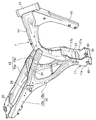
先ず図1および図2において、自動二輪車の車体フレームFは、前輪WFを軸支するフロントフォーク11および操向ハンドル12を操向可能に支承するヘッドパイプ13と、該ヘッドパイプ13から後下がりに延びるメインフレーム14と、該メインフレーム14に連設される左右一対のサブフレーム15,15と、前記メインフレーム14の前端部に連設されるとともにメインフレーム14よりも急角度で後下がりに延びるダウンフレーム16と、前記メインフレーム14の後端部に結合されるピボットフレーム17とを備える。
1 and 2, a body frame F of a motorcycle includes a
前記メインフレーム14の後部および前記ピボットフレーム17よりも前方には内燃機関Eの機関本体20が配置される。この機関本体20は、前記メインフレーム14、前記ダウンフレーム16および前記ピボットフレーム17で囲まれるようにして前記車体フレームFに搭載されるものであり、前記ダウンフレーム16の下端部に設けられるエンジンハンガ18および前記ピボットフレーム17で前記機関本体20が支持される。
An
前記機関本体20の上方でメインフレーム14上には燃料タンク21が搭載され、その燃料タンク21の後方に配置されるタンデム型の乗車用シート22が前記サブフレーム15,15で支持される。
A
前記ピボットフレーム17は、車幅方向で相互に間隔をあけて対向して上下方向に延びる左右一対の側板部17a,17aと、それらの側板部17a,17aの上部間を連結する連結板部17bとを一体に有するようにして、金属板材が屈曲成形されて成るものであり、左右一対の側板部17a,17a間には、両端をそれらの側板部17a,17aから外側方に突出させるようにしてスイングアーム支持筒23が設けられる。
The
前記サブフレーム15は、プレス加工された金属板材から成る左右一対のフレーム構成部材の周縁部の突き合わせ接合によって中空閉断面を有するように構成されるものであり、このサブフレーム15は、前記メインフレーム14の中間部に前端部が連設されて該メインフレーム14から後方に延びるシートレール部15aと、該シートレール部15aの前後方向中間部から前下がりに延びるリヤフレーム部15bとを有し、側面視では略Y字状をなすように形成される。
The
左右一対のシートレール部15a,15aに対する前記リヤフレーム部15b,15bの連設部よりも前方の部分で両シートレール部15a,15a間には第1のクロス部材24が設けられ、両シートレール部15a,15aの後端部間には第2のクロス部材25が設けられる。また前記乗車用シート22は両サブフレーム15,15の前記シートレール部15a,15aで支持され、前記リヤフレーム部15b,15bの前端部は前記ピボットフレーム17に連設される。
A
前記シートレール部15a,15aへの前記リヤフレーム部15b,15bの連設部に対応する部分で前記シートレール部15a,15a間には、外端部をそれらのシートレール部15a,15aから突出させるようにしてクロスパイプ26が設けられる。一方、前記ピボットフレーム17には、後輪WRを後端部で軸支するスイングアーム27の前端部が、前記スイングアーム支持筒23に挿通される支軸としてのボルト28を介して揺動可能に支承されており、前記クロスパイプ26の両端部および前記スイングアーム27間にはリヤクッション29がそれぞれ設けられる。
A portion corresponding to the connecting portion of the
前記燃料タンク21の前部ならびにその前部寄り両側面は前記車体フレームFの前部で支持されるシュラウド30で覆われており、前記エンジンEの一部、前記メインフレーム14の一部および前記サブフレーム15の前部は、前記車体フレームFで支持されて前記燃料タンク21の下方に配置される左右一対のサイドカバー31で側方から覆われ、前記サブフレーム15の後部はサブフレーム15で支持されたリヤカバー32で側方から覆われる。
The front portion of the
図3を併せて参照して、前記内燃機関Eが備える吸気装置34は前記機関本体20におけるシリンダヘッド33の後部側面に接続されており、この吸気装置34は、側面視で前記サブフレーム15のシートレール部15aおよびリヤフレーム部15bで囲まれる位置に配置されて前記サイドカバー31で側方から覆われるエアクリーナ35と、該エアクリーナ35に接続されるスロットルボディ36と、該スロットルボディ36および前記シリンダヘッド33間を結ぶ吸気管37とを備える。また前記エアクリーナ35の下部には、前記サイドカバー31を開放することで工具の出し入れを可能としたツールボックス38が設けられる。
Referring also to FIG. 3, the
また前記内燃機関Eが備える排気装置40は前記シリンダヘッド33の前部側面に接続されるものであり、前記シリンダヘッド33の前部側面から前記機関本体20の下方を通って後方に延びる排気管41と、前記後輪WRの右側方で後上がりに延びるように配置されて前記排気管41の下流端に接続される排気マフラー42とを備える。
Further, the
前記排気管41の前記排気マフラー42寄り下流端部は、排気管41に取付けられる遮熱カバー43で覆われ、前記排気マフラー42は、該排気マフラー42および右側のステップホルダ49に取付けられるマフラーカバー44で覆われる。
The downstream end of the
図4を併せて参照して、前記ピボットフレーム17における前記側板部17a,17aの下部内面には、相互に同軸に配置される短円筒状の筒部材45,45が固着されており、メインスタンド46がその基部に備える円筒部46aが前記筒部材45,45間に配置され、筒部材45,45および円筒部46aにスタンド軸47が挿通される。これによりメインスタンド46が前記スタンド軸47を介して前記ピボットフレーム17の下部に回動可能に支持される。
Referring also to FIG. 4, short
前記スイングアーム27は前記後輪WRの左右両側で前後方向に延びる左右一対のアーム部27a,27aを有しており、それらのアーム部27a,27aの前端部は、前記ピボットフレーム17に設けられるスイングアーム支持筒23の両端部に並ぶように配置される。
The
車幅方向で前記ピボットフレーム17の左右外側にはステップホルダ48,49が配置されており、それらのステップホルダ48,49は、前記スイングアーム27のアーム部27a,27aの前端部を前記ピボットフレーム17の前記スイングアーム支持筒23との間に挟むように配置され、左側のステップホルダ48側から該ステップホルダ48、左側のアーム部27aの前端部、前記スイングアーム支持筒23、右側の前記アーム部27aの前端部および右側のステップホルダ49に、前記左側のステップホルダ48に外側から当接、係合する拡径突部28aを有する前記ボルト28が挿通され、右側のステップホルダ49からの前記ボルト28の突出部に、右側のステップホルダ49に当接、係合するナット50が螺合される。
すなわち前記ピボットフレーム17には、前記スイングアーム27の前端部がボルト28を介して揺動可能に支承されるとともに、左右一対のステップホルダ48,49が前記ボルト28を介して固定されることになる。
That is, the
前記ステップホルダ48,49は、前記ボルト28を介して前記ピボットフレーム17に固定される支持部48a,49aと、該支持部48a,49aから車両前後方向後方に延びる前後延出部48b,49bと、側面視で前記スイングアーム27の下方まで延びるようにして前記支持部48a,49aから下方に延びる上下延出部48c,49cとを一体に有するように形成される。
The
ところで、左側のステップホルダ48の上下延出部48cが、該上下延出部48cの下端部を前記ピボットフレーム17の左側の側板部17aの下部に近接させるように形成されるのに対して、右側のステップホルダ49の上下延出部49cは、該上下延出部49cの下端部を前記ピボットフレーム17の右側の側板部17aの下部から比較的離隔した位置に配置するように形成されており、前記ピボットフレーム17における両側板部17a,17aの下部には、右側の側板部17aからの突出量を左側の側板部17aからの突出量よりも大きくした支持筒51が両側板部17a,17aを貫通するようにして固着される。この支持筒51の両端部に当接された前記上下延出部48c,49cが、前記上下延出部48c,49cおよび前記支持筒51に挿通されるボルト52(図3および図6参照)ならびに該ボルト52に螺合されるナット(図示せず)によって前記ピボットフレーム17の下部に固定される。すなわちステップホルダ48,49は、その支持部48a,49aが前記ピボットフレーム17に固定されるとともに、上下延出部48c,49cの下部が前記ピボットフレーム17に固定される。
By the way, the
また前記ステップホルダ48,49には、前記乗車用シート22の後部に乗った同乗者が足を載せることを可能としたピリオンステップ53,53が取付けられるものであり、それらのピリオンステッップ53,53は、前記前後延出部48b,49bの後部に設けられた前記支持部48a,49aに、ステップホルダ48,49側に折り畳んだ折り畳み位置と、前記ステップホルダ48,49から側方に突出した突出位置との間での回動を可能として取付けられる。
Further, the
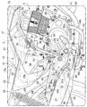
図5および図6を併せて参照して、右側の前記ステップホルダ49には、ブレーキペダル54がペダル軸55を介して回動可能に支承されるものであり、右側のステップホルダ49の前記上下延出部49cは、車両前後方向後方に突出するペダル軸支持部49eを一体に有し、車幅方向に延びる前記ペダル軸55の一端部が前記ペダル軸支持部49eにモールド結合される。
Referring to FIGS. 5 and 6 together, a
前記ペダル軸55は、側面視で前記スイングアーム27よりも下方かつ前記排気装置40の一部と重なる位置に少なくとも一部が配置されるものであり、この実施の形態では前記排気装置40における排気管41の下流端部に、側面視で前記ペダル軸55の一部が配置される。また、前記ペダル軸55は、平面視でそれの幅内において前記スイングアーム27と交差している。
The
前記ブレーキペダル54は、前記ペダル軸55で回動可能に支持される円筒状の支持筒部54aと、該支持筒部54aから車両前後方向に沿う前方に延びる横アーム部54bと、該横アーム部54bの前端に設けられるペダル部54cと、上下に延びるようにして前記支持筒部54aに連設される縦アーム部54dとを備えており、このブレーキペダル54は、側面視で前記スイングアーム27よりも下方で前記ペダル軸55を介して前記上下延出部49cのペダル軸支持部49eに回動可能に支承されることになる。
The
前記横アーム部54bは、車両前後方向に沿う後端部および前端部を上方に屈曲させた金属パイプから成り、この金属パイプの後端部が前記支持筒部54aに溶接される。また前記縦アーム部54dは、少なくとも上端部を前記前後延出部49bの裏側に配置するようにして、車幅方向で前記スイングアーム27および前記ステップホルダ49間に配置される。
The
前記ブレーキペダル54における前記横アーム部54bの後端部に、前記ブレーキペダル54を戻し側に付勢するばね力を発揮するリターンスプリング56の一端部が連結され、このリターンスプリング56の他端部は、前記ステップホルダ49における上下延出部49cの下端部に連結される。
One end portion of a
また前記ステップホルダ49の下部には、前記ブレーキペダル54の戻り側の回動端を規制するストッパ57が取付けられるものであり、この実施の形態では前記ステップホルダ49における上下延出部49cの下端部に、前記ストッパ57がボルト58およびナット59によって取付けられる。
A
図1に注目して、前記操向ハンドル12の右端部には、ブレーキレバー61が回動操作可能に取付けられるとともに、該ブレーキレバー61の回動操作に応じてブレーキ液圧を出力する第1のマスタシリンダ62が取付けられる。
Referring to FIG. 1, a
また前輪WFには、前記ブレーキレバー61の操作に応じてブレーキ作動するとともに前記ブレーキペダル54の踏み込み操作によってもブレーキ作動するディスクブレーキB1が設けられ、後輪WRには、前記ブレーキペダル54の踏み込み操作によってブレーキ作動するドラムブレーキB2が設けられる。
Further, the front wheel WF is provided with a disc brake B1 which is braked according to the operation of the
図6に注目して、前記右側のステップホルダ49の裏面側には、前記ディスクブレーキB1をブレーキ作動させる液圧を発生させることを可能とした第2のマスタシリンダ63が配置されており、この第2のマスタシリンダ63は、前上がりにわずかに傾斜しつつ前記ステップホルダ49における前後延出部49bの前部の裏面側に取付けられる。すなわち第2のマスタシリンダ63は、前記前後延出部49bの前部の裏面に一対のボルト64,64によって取付けられる。
Paying attention to FIG. 6, a
前記ブレーキペダル54による操作力は、イコライザ65を介して第2のマスタシリンダ63に入力されるとともに、後輪WRのドラムブレーキB2にブレーキ操作力を機械的に伝達するブレーキ操作力伝達部材としてのロッド66にも入力されるものであり、前記イコライザ65の中間部は、前記ブレーキペダル54における縦アーム部54dの裏側で該縦アーム部54dの上端部に軸67を介して回動可能に連結される。
The operation force by the
前記イコライザ65の上端部には、該イコライザ65の前方に配置される第2のマスタシリンダ63のピストンロッド68が連結ピン69を介して連結される。また前記イコライザ65の下端部には、前記ロッド66の一端部が連結ピン70を介して連結され、このロッド66の他端部は、図1で明示するように、前記ドラムブレーキB2が備える入力腕71の先端部に連結ピン72を介して連結される。
A
前記イコライザ65およびステップホルダ49間には、前記ブレーキペダル54の踏み込み操作に応じて、前記ロッド66を牽引するように前記イコライザ65が作動した後に第2のマスタシリンダ63の前記ピストンロッド68を押し込むようにして、ブレーキペダル54の踏み込み操作初期の前記縦アーム部54dに対する前記イコライザ65の相対姿勢を制御するディレイスプリング73が設けられており、前記イコライザ65の上端部側と、前記前後延出部49bの後部との間に介設される前記ディレイスプリング73は、前記前後延出部49bの長手方向に沿って延びて前後延出部49bの裏側に配置される。
Between the
第2のマスタシリンダ63から出力される液圧を導く液圧ホース75は、右側のサイドカバー31およびシュラウド30内を経て前輪WFのディスクブレーキB1のキャリパ76に接続される。また第1のマスタシリンダ62からの液圧を導く液圧ホース77も前記キャリパ76に接続される。
A
右側の前記サイドカバー31の下縁31aは、右側の前記ステップホルダ49の少なくとも前部の上縁49fを外方から覆いつつ該上縁49fに沿うように配置されており、第2のマスタシリンダ63も、その一部が右側のステップホルダ49の裏側から右側の前記サイドカバー31内に突出するように配置され、前記液圧ホース75は前記サイドカバー31内で第2のマスタシリンダ63に接続される。
The
図7を併せて参照して、第2のマスタシリンダ63にブレーキ液を供給するためのリザーバ78が第2のマスタシリンダ63の前上方に配置されており、このリザーバ78は、車体フレームFのメインフレーム14に固定されるステー79で支持される。リザーバ78はブレーキ液を導くホース80で第2のマスタシリンダ63に接続される。
Referring also to FIG. 7, a
しかも前記リザーバ78は、その内部に貯留されるブレーキ液の貯留レベルを外部から視認することを可能として透明な合成樹脂で形成されており、このリザーバ78を外側方から覆う右側の前記サイドカバー31には、前記リザーバ78の一部を外部から視認可能とした点検窓81が形成される。
Moreover, the
図5および図6に注目して、右側の前記ステップホルダ49には、前記ブレーキペダル54の作動を検知するブレーキスイッチ84が取付けられており、このブレーキスイッチ84は、前記ステップホルダ49における前後延出部49bの長手方向に沿って長く延びて該前後延出部49bの後部裏面に支持される。すなわち前記前後延出部49bの後部裏面には、支持板部49gが一体に突設されており、前記ブレーキスイッチ84は、該支持板部49gに挿通、支持される。
5 and 6, a
このブレーキスイッチ84には、前記ブレーキペダル54における前記縦アーム部54dの上端部が連結されるものであり、この実施の形態では、前記縦アーム部54dの上端部に係合、連結されるフック部85aを一端部に有する連結ロッド85の他端部がスプリング86を介して前記ブレーキスイッチ84に連結される。
The
前記ブレーキスイッチ84から延出されるブレーキスイッチケーブル87は、前記前後延出部49bの上部の裏面側を前方側に延びるように配索されるのであるが、そのブレーキスイッチケーブル87の一部は、前記前後延出部49bの上部の裏面に取付けられた2つのケーブルホルダ88,89によって前後延出部49bの裏面側で支持される。
The
2つの前記ケーブルホルダ88,89のうち前方側のケーブルホルダ89のさらに前方で前記ステップホルダ49における前記前後延出部49bの裏面には、車幅方向に指向する締結部材であるボルト90によってクリップ支持部材91が締結されており、車両前後方向に沿う前方または後方(この実施の形態では後方)に臨む支持面93が前記クリップ支持部材91に形成され、その支持面93に支持されるケーブルクリップ92で前記ブレーキスイッチケーブル87が保持される。
A
前記クリップ支持部材91は、前記ボルト90で前記前後延出部49bの裏面に締結される取付け板部91aと、該取付け板部91aに連設される支持板部91bとを一体に有しており、前記支持板部91bに前記支持面93が形成される。
The clip support member 91 integrally includes a mounting plate portion 91a fastened to the back surface of the front /
しかも前記前後延出部49bの裏面には、前記取付け板部91aを前後から挟む一対の突部94,95が一体に突設されており、それらの突部94,95間に挟まれることで前記取付け板部91aの回り止めが果たされるので、単一のボルト90だけで前記クリップ支持部材91を前記前後延出部49bに締結することができる。
In addition, a pair of protrusions 94 and 95 that sandwich the mounting plate 91a from the front and rear are integrally formed on the back surface of the front and
また前記突部94,95のうち後方側の突部95は、前記ブレーキペダル54における前記縦アーム部54dに前方から対向する位置に配置されており、前記ブレーキペダル54を最大限踏み込んだ際に前記縦アーム部54dに当接することでブレーキペダル54の最大回動位置を規制する。
Further, of the protrusions 94 and 95, the rear protrusion 95 is disposed at a position facing the
次にこの実施の形態の作用について説明すると、車体フレームFに固定される右側のステップホルダ49に、同乗者が足を載せることを可能としたピリオンステップ53が取付けられるとともにブレーキペダル54がペダル軸55を介して回動可能に支承され、前記ブレーキペダル54の作動を検知するブレーキスイッチ84が前記ステップホルダ49に取付けられるのであるが、前記ステップホルダ49は、ボルト28を介してピボットフレーム17に固定される支持部49aと、その支持部49aから車両前後方向後方に延びる前後延出部49bとを一体に有するように形成され、ブレーキペダル54が、少なくとも上端部を前記前後延出部49bの裏側に配置するようにして上下に延びる縦アーム部54dを有するように形成され、前後延出部49bの長手方向に沿って長く延びて該前後延出部49bの裏面に支持される前記ブレーキスイッチ84に、前記縦アーム部54dの上端部が連結されるので、ステップホルダ49の大型化および部品点数の増大を回避しつつブレーキスイッチ84が外部から見えないようにして意匠性を高めることができるとともにブレーキスイッチ84への悪戯防止を図ることができる。
Next, the operation of this embodiment will be described. A
またブレーキスイッチ84から延出されるブレーキスイッチケーブル87の一部が前記前後延出部49bの裏面側で支持されるので、ブレーキスイッチ84の近傍ではブレーキスイッチケーブル87も外部に露出することがなく、意匠性をより高めることができ、ブレーキスイッチケーブル87への悪戯防止を図ることができる。
Further, since a part of the
またステップホルダ49に、前記支持部49aから下方に延びる上下延出部49cが一体に形成され、前記ブレーキペダル54を戻し側に付勢するばね力を発揮するようにして該ブレーキペダル54に一端部が連結されるリターンスプリング56の他端部が、前記上下延出部49cの下端部に連結されるので、上下方向でのスペースが限られているステップホルダ49の近傍でリターンスプリング56の配置に伴う大型化を抑制することができる。
Further, the
また前記縦アーム部54dの上端前部に前記ブレーキスイッチ84が連結されるので、前後延出部49bの長手方向に沿って長く延びるブレーキスイッチ84のストローク長さを確保することができる。
In addition, since the
また前記ステップホルダ49の上方に配置されて前記車体フレームFに支持されるサイドカバー31の下縁31aが、前記ステップホルダ49の少なくとも前部の上縁49fに沿うように配置されるので、ブレーキスイッチケーブル87を前記ステップホルダ49から前記サイドカバー31の裏面側に延出するようにし、ブレーキスイッチケーブル87が外部に極力露出しないようにして意匠性をより高めるとともにブレーキスイッチケーブル87への悪戯防止効果をより高めることができる。
Since the
また前記ブレーキスイッチケーブル87を保持するケーブルクリップ92を支持する支持面93を車両前後方向の後方に臨ませるクリップ支持部材91が、車幅方向に指向するボルト90で前記ステップホルダ49における前記前後延出部49bの裏面に締結されるので、車両前後方向に延びるブレーキスイッチケーブル87の配索方向をケーブルクリップ92で車幅方向に変えることが可能であり、クリップ支持部材91を締結するボルト90が車幅方向に指向しているので、クリップ支持部材91を取付けるためにステップホルダ49に施す加工が容易となる。
A clip support member 91 that causes a
また前記ステップホルダ49の上下延出部49cは、側面視で前記スイングアーム27の下方まで延びるようにして前記支持部49aから下方に延びており、側面視で前記スイングアーム27よりも下方で前記上下延出部49cに前記ペダル軸55を介して回動可能に支承される前記ブレーキペダル54が、車幅方向で前記スイングアーム27および前記ステップホルダ49間に配置されるようにして上下に延びる縦アーム部54dを有するように形成され、前記ペダル軸55は、平面視でそれの幅内においてスイングアーム27と交差するとともに、該ペダル軸55の少なくとも一部は、内燃機関Eの排気装置40の一部に側面視で重なる位置に配置されるので、ブレーキペダル54の車幅方向側方に排気装置40が配設されていてもブレーキペダル54を充分な支持力でステップホルダ49に支持することができる。
Further, the vertically extending
また前輪WFに設けられたディスクブレーキB1をブレーキ作動させる液圧を発生することを可能として前記ステップホルダ49に取付けられる第2のマスタシリンダ63と、後輪WRに設けられたドラムブレーキB2にブレーキ操作力を機械的に伝達するロッド66とに、前記ブレーキペダル54から入力されるブレーキ操作力がイコライザ65によって分配されるので、前記ブレーキペダル54の操作によって前輪WFのディスクブレーキB1と、後輪WRのドラムブレーキB2とを連動してブレーキ作動させるようにした連動ブレーキを構成することができる。
Further, a brake is applied to the
また第2のマスタシリンダ63に一端部が連結されるとともに前記ロッド66に他端部が連結される前記イコライザ65の中間部が、前記縦アーム部54dの裏側で該縦アーム部54dに連結されるので、ロッド66をスイングアーム27側に極力近づけて配置し、後輪WRのドラムブレーキB2に車幅方向でより近づけて前記ロッド66を配置することができる。
An intermediate portion of the
また前記イコライザ65の前記一端部側と、前記ステップホルダ49が一体に有して車両前後方向後方に延びる前後延出部49bの後部との間に、その前後延出部49bの長手方向に沿って延びて前後延出部49bの裏側に配置されるディレイスプリング73が介設されるので、意匠性を高めつつディレイスプリング73の長さを確保して必要なばね力を確保することができる。
Further, between the one end side of the
さらに前記ブレーキペダル54の戻り側の回動端を規制するストッパ57が、前記ステップホルダ49の下部に取付けられるので、ストッパ57を含めてステップホルダ49全体をユニット化することができ、組付け性を高めることができる。
Further, since the
以上、本発明の実施の形態について説明したが、本発明は上記実施の形態に限定されるものではなく、その要旨を逸脱することなく種々の設計変更を行うことが可能である。 Although the embodiments of the present invention have been described above, the present invention is not limited to the above-described embodiments, and various design changes can be made without departing from the gist thereof.
Claims (3)
前記ステップホルダ(49)は、前記ピボットフレーム(17)の車幅方向外側に配置されるとともに該ピボットフレーム(17)に固定される支持部(49a)と、側面視で前記スイングアーム(27)の下方まで延びるようにして前記支持部(49a)から下方に延びる上下延出部(49c)とを一体に有するように形成され、
前記ブレーキペダル(54)は、車幅方向で前記スイングアーム(27)および前記ステップホルダ(49)間に配置されるようにして上下に延びる縦アーム部(54d)を有するように形成されて、側面視で前記スイングアーム(27)よりも下方で前記上下延出部(49c)に支承され、
前記ペダル軸(55)は、平面視でそれの幅内において前記スイングアーム(27)と交差するとともに、該ペダル軸(55)の少なくとも一部は、前記内燃機関(E)の排気装置(40)の一部に側面視で重なる位置に配置され、
前輪(WF)に設けられたディスクブレーキ(B1)をブレーキ作動させる液圧を発生することを可能として前記ステップホルダ(49)に取付けられるマスタシリンダ(63)に一端部が連結され、且つブレーキ操作力を後輪(WR)に設けられたドラムブレーキ(B2)に機械的に伝達するブレーキ操作力伝達部材(66)に他端部が連結されるイコライザ(65)の中間部が、前記縦アーム部(54d)の裏側で該縦アーム部(54d)に連結されて、前記ブレーキペダル(54)から入力されるブレーキ操作力を前記マスタシリンダ(63)と前記ブレーキ操作力伝達部材(66)とに分配することを特徴とする自動二輪車。A pivot frame (17) constituting a part of the vehicle body frame (F) that supports the tandem riding seat (22) and a rear wheel (WR) are pivotally supported at the rear end portion, and the front end portion is a pivot shaft ( 28) and a swing arm (27) that is swingably supported on the pivot frame (17), and a pillion step (53) that allows a passenger to place a foot on it. F) A step holder (49) fixed to the step holder (49) and a brake pedal (54) rotatably supported by the step holder (49) via a pedal shaft (55) provided on the step holder (49). A motorcycle in which the engine body (20) of the internal combustion engine (E) is disposed in front of the pivot frame (17),
The step holder (49) is disposed on the outer side in the vehicle width direction of the pivot frame (17) and fixed to the pivot frame (17), and the swing arm (27) in a side view. An upper and lower extension part (49c) extending downward from the support part (49a) so as to extend to the lower part of the support part (49a),
The brake pedal (54) is formed to have a vertical arm portion (54d) extending vertically so as to be disposed between the swing arm (27) and the step holder (49) in the vehicle width direction, It is supported by the vertical extension part (49c) below the swing arm (27) in a side view,
The pedal shaft (55) intersects the swing arm (27) within the width thereof in plan view, and at least a part of the pedal shaft (55) is an exhaust device (40) of the internal combustion engine (E). ) In a position that overlaps part of the side view,
One end of the disc brake (B1) provided on the front wheel (WF) is connected to the master cylinder (63) attached to the step holder (49) so as to generate a hydraulic pressure for operating the brake, and brake operation is performed. An intermediate portion of an equalizer (65) whose other end is coupled to a brake operation force transmission member (66) that mechanically transmits a force to a drum brake (B2) provided on the rear wheel (WR) is the vertical arm. The brake operation force input from the brake pedal (54) is connected to the vertical arm portion (54d) on the back side of the portion (54d) and the master cylinder (63) and the brake operation force transmission member (66). A motorcycle characterized by distributing to the motorcycle.
Applications Claiming Priority (3)
| Application Number | Priority Date | Filing Date | Title |
|---|---|---|---|
| JP2013177804 | 2013-08-29 | ||
| JP2013177804 | 2013-08-29 | ||
| PCT/JP2014/063969 WO2015029520A1 (en) | 2013-08-29 | 2014-05-27 | Automatic two-wheeled vehicle |
Publications (2)
| Publication Number | Publication Date |
|---|---|
| JP6077662B2 true JP6077662B2 (en) | 2017-02-15 |
| JPWO2015029520A1 JPWO2015029520A1 (en) | 2017-03-02 |
Family
ID=52586101
Family Applications (1)
| Application Number | Title | Priority Date | Filing Date |
|---|---|---|---|
| JP2015534030A Active JP6077662B2 (en) | 2013-08-29 | 2014-05-27 | Motorcycle |
Country Status (6)
| Country | Link |
|---|---|
| JP (1) | JP6077662B2 (en) |
| CN (1) | CN105517883B (en) |
| BR (1) | BR112016003548B1 (en) |
| MY (1) | MY177121A (en) |
| PH (1) | PH12016500370B1 (en) |
| WO (1) | WO2015029520A1 (en) |
Families Citing this family (4)
| Publication number | Priority date | Publication date | Assignee | Title |
|---|---|---|---|---|
| JP6209792B2 (en) | 2016-03-31 | 2017-10-11 | 本田技研工業株式会社 | Reservoir tank mounting part structure for saddle-ride type vehicles |
| US11072393B2 (en) | 2017-01-12 | 2021-07-27 | Honda Motor Co., Ltd. | Transmission for saddled vehicle |
| BR112019014573B1 (en) * | 2017-02-03 | 2023-05-02 | Honda Motor Co., Ltd | FRONT/REAR INTERLOCK BRAKING DEVICE FOR SADDLE TYPE VEHICLES |
| WO2019138428A1 (en) * | 2018-01-12 | 2019-07-18 | Hero MotoCorp Limited | Speed deceleration system of vehicle |
Citations (3)
| Publication number | Priority date | Publication date | Assignee | Title |
|---|---|---|---|---|
| JP2010234940A (en) * | 2009-03-31 | 2010-10-21 | Honda Motor Co Ltd | Saddle-riding type vehicle |
| JP2011143767A (en) * | 2010-01-13 | 2011-07-28 | Honda Motor Co Ltd | Interlocking brake device for motorcycle |
| JP2013154845A (en) * | 2012-01-31 | 2013-08-15 | Honda Motor Co Ltd | Brake device for motorcycle |
Family Cites Families (1)
| Publication number | Priority date | Publication date | Assignee | Title |
|---|---|---|---|---|
| JP2845838B2 (en) * | 1996-09-19 | 1999-01-13 | 静岡日本電気株式会社 | Radio selective call receiver |
-
2014
- 2014-05-27 WO PCT/JP2014/063969 patent/WO2015029520A1/en active Application Filing
- 2014-05-27 CN CN201480048113.7A patent/CN105517883B/en active Active
- 2014-05-27 JP JP2015534030A patent/JP6077662B2/en active Active
- 2014-05-27 BR BR112016003548-8A patent/BR112016003548B1/en active IP Right Grant
- 2014-05-27 MY MYPI2016700646A patent/MY177121A/en unknown
-
2016
- 2016-02-24 PH PH12016500370A patent/PH12016500370B1/en unknown
Patent Citations (3)
| Publication number | Priority date | Publication date | Assignee | Title |
|---|---|---|---|---|
| JP2010234940A (en) * | 2009-03-31 | 2010-10-21 | Honda Motor Co Ltd | Saddle-riding type vehicle |
| JP2011143767A (en) * | 2010-01-13 | 2011-07-28 | Honda Motor Co Ltd | Interlocking brake device for motorcycle |
| JP2013154845A (en) * | 2012-01-31 | 2013-08-15 | Honda Motor Co Ltd | Brake device for motorcycle |
Also Published As
| Publication number | Publication date |
|---|---|
| PH12016500370A1 (en) | 2016-05-02 |
| JPWO2015029520A1 (en) | 2017-03-02 |
| WO2015029520A1 (en) | 2015-03-05 |
| PH12016500370B1 (en) | 2016-05-02 |
| BR112016003548B1 (en) | 2022-01-04 |
| CN105517883A (en) | 2016-04-20 |
| BR112016003548A2 (en) | 2017-08-01 |
| CN105517883B (en) | 2018-05-01 |
| MY177121A (en) | 2020-09-07 |
Similar Documents
| Publication | Publication Date | Title |
|---|---|---|
| JP4825543B2 (en) | Brake support structure | |
| JP6077662B2 (en) | Motorcycle | |
| JP6141924B2 (en) | Step structure in motorcycles | |
| US8393630B2 (en) | Straddle-type vehicle | |
| JP5848294B2 (en) | Motorcycle | |
| JP4612005B2 (en) | Foot brake structure for scooter type vehicles | |
| JP6244321B2 (en) | Motorcycle | |
| WO2017056281A1 (en) | Braking coordination device for saddled vehicles | |
| BR112018015361B1 (en) | TYPE VEHICLE TO ASSEMBLE | |
| JP6166333B2 (en) | Harness guide structure for saddle-ride type vehicles | |
| CN108883807B (en) | Saddle-riding type vehicle | |
| JP6796196B2 (en) | Front-rear interlocking brake device for saddle-riding vehicles | |
| JP6761487B2 (en) | Saddle-type vehicle | |
| JP5881125B2 (en) | Routing structure of braking force transmission member in motorcycle | |
| JP6710718B2 (en) | Saddle type vehicle | |
| JP2681504B2 (en) | Bracket structure for motorcycle footrest | |
| JP6839301B2 (en) | Brake piping structure for saddle-mounted vehicles | |
| JP6472530B2 (en) | Body frame for motorcycle | |
| JP2005240885A (en) | Pad residue checking structure in disk brake of vehicle | |
| JP7390330B2 (en) | saddle type vehicle | |
| JP6757770B2 (en) | Front structure of saddle-mounted vehicle | |
| JP6468248B2 (en) | Interlocking brake device for saddle riding type vehicles | |
| JP2008080861A (en) | Motorcycle | |
| BR112020003165B1 (en) | BRAKE PIPE STRUCTURE FOR MOUNTED TYPE VEHICLES | |
| JP2020032733A (en) | Saddle-riding type vehicle |
Legal Events
| Date | Code | Title | Description |
|---|---|---|---|
| TRDD | Decision of grant or rejection written | ||
| A01 | Written decision to grant a patent or to grant a registration (utility model) |
Free format text: JAPANESE INTERMEDIATE CODE: A01 Effective date: 20161214 |
|
| A61 | First payment of annual fees (during grant procedure) |
Free format text: JAPANESE INTERMEDIATE CODE: A61 Effective date: 20170112 |
|
| R150 | Certificate of patent or registration of utility model |
Ref document number: 6077662 Country of ref document: JP Free format text: JAPANESE INTERMEDIATE CODE: R150 |